Turquoise Energy Report #176
Covering
January 2023 (Posted February 12th 2023)
Lawnhill BC Canada - by Craig Carmichael
(CraigXC at Post dot com)
www.TurquoiseEnergy.com
= www.ElectricCaik.com
= www.ElectricHubcap.com
Month In "Brief"
(Project Summaries etc.)
- Magnetic Variable Torque Converter for ZX40 truck - Soldering
Alume: Wow, easy! - Another Peltier Module Heatsink Idea - Battery
chemie, design, experiments... not without some Success - Living Titan
(the planet orbiting Saturn)
In
Passing
(Miscellaneous topics, editorial comments & opinionated rants)
- Scattered Thots - ESD
- Detailed
Project Reports
-
Electric
Transport - Electric Hubcap Motor Systems
* Magnetic Variable Torque Converter with Planetary Gear: The
Future of the Automotive Industry! Assembling/Installing one for
Miles Truck: Almost working.
Other "Green"
& Electric Equipment Projects
* Indoor & LED Gardening
* Plastic recycling 2.0 - No smells at 500° in kitchen oven; PETE
failure; PE Bleach bottle melt... not long enough in the oven.
Electricity Storage:
Batteries
* Oodles of eperiments: Gelled Co(OH)2 + Zn Salt Cells - Theoretical
about cobalt & its
oxides - Didn't work as expected but the lower voltage redox reaction
that does work has double amp-hours: 3 to 5 times the amp-hours of
nickel! - Cobalt electrode conductivity additive: copper powder - Zinc
grit from alkaline 'D' cells - Super lightweight "packaging tape" cell:
over 100 WH/Kg - 35 WH rechargeable 'D' cells? - A Ni-Zn cell
Electricity Generation
* My Solar Power System:
- The Usual Latest Daily/Monthly
Solar Production log et cetera - Monthly/Annual Summaries,
Estimates, Notes
The day after posting my lamentations (under "batteries")
that I couldn't seem to get a good camera, I went to the thrift shop in
town and got a great Fuji camera for 2$ that takes fabulous, sharp
pictures at any focus/distance. I just had to put in an SD memory card
and four new AA batteries. (Ni-MH rechargeable, of course. And I had 4
crappy cameras to donate to the thrift shop!)
What were my project priorities for the month? Although
the 6mm shank router bits had arrived, I decided to set aside the
project of making a magnet placement jig for the new motor project. I
had been working on new chemie batteries for two months, had a new idea
or two, and I decided they took priority.
On the 14th the bearing for the truck arrived - presumably
the last piece needed to make the "road-worthy" version of the magnetic
variable torque converter conceived last August which "jury rigged"
experiments in September had shown seemed to work so well. But there's
always plenty to do and I'm trying to avoid plunging off in all
directions so I stuck with the battery experiments.
Then on the 28th my friend Tom called from Victoria. There
was a second Miles ZX40 truck sold later by Burnaby Repo [.com] back in
2017 which my friend Jim had purchased, charged up and sold again. (It
went for a song - 1800$ or something. I had paid way over 5000!) Tom,
who is now really into making battery packs for electric vehicles, was
working with the person who bought it from Jim to make it an effective,
roadworthy vehicle. I had told him that the magnetic torque converter
would make it fantastic. Apparently they've been waiting for me to get
my Miles truck working to see how it goes! So I decided I'd better get
back to doing the truck. I thought I'd have it going very early in
February so I put off doing this newsletter pending that, but success
was elusive mostly for readily solvable mechanical reasons.
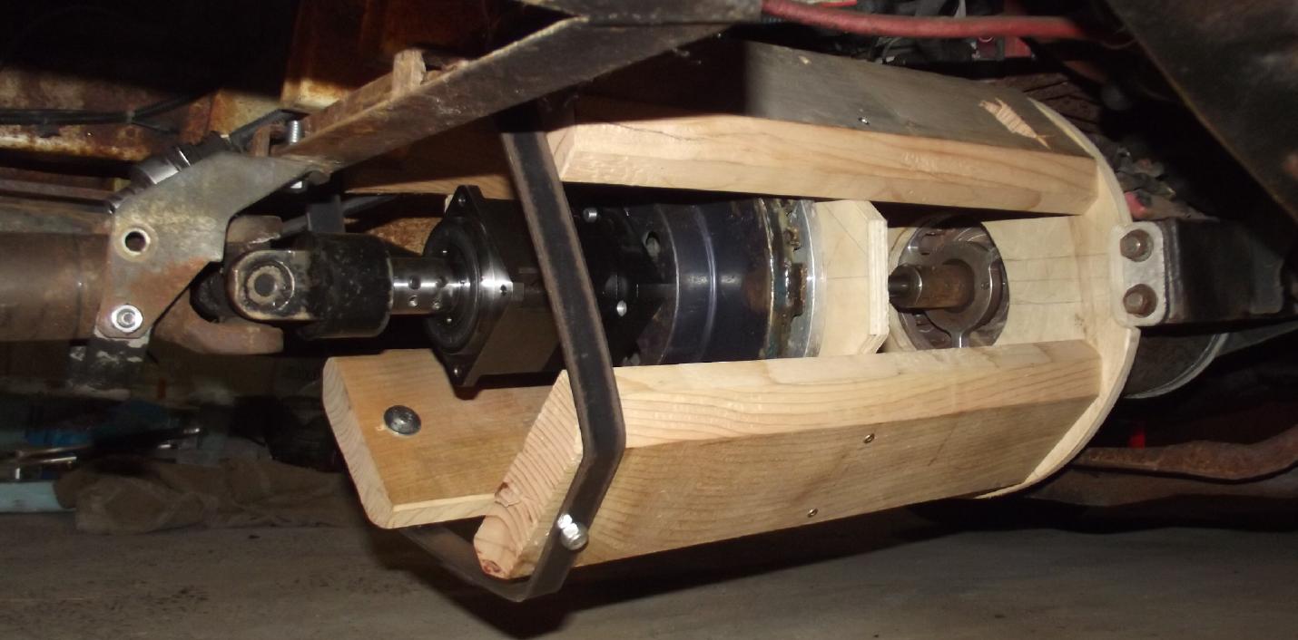
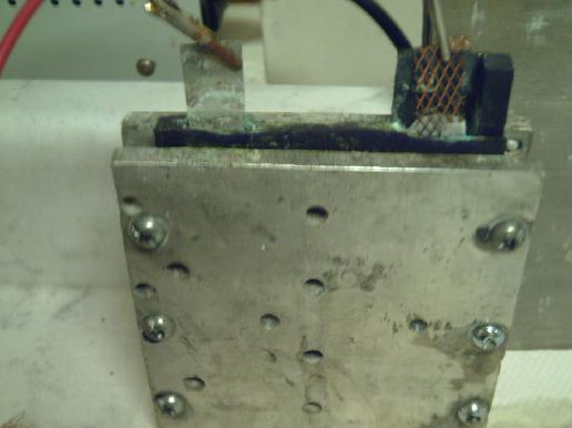
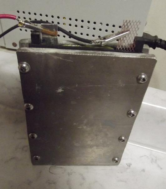
Magnetic Variable Torque Converter/Miles Truck
 Wooden housing to avoid
interference with
magnets (to be well epoxied, and closed off from road dirt)
Wooden housing to avoid
interference with
magnets (to be well epoxied, and closed off from road dirt)
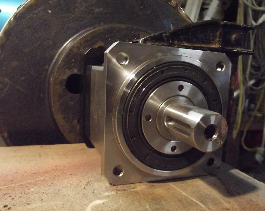
RIGHT to LEFT: * Curtis AC35(?) 72 volt, high RPM induction motor
- with splined socket shaft
* Motor end of motor-to-planetary-gear shaft (just visible) - turns
alume disk & sun gear
* Plywood wall holds bearing to steady the long shaft
* 10 inch Alume rotor/disk - spins with motor
* 10 inch Magnet rotor (from a brake disk) - Hallbach configuration -
spins with planetary gear body
* 10:1 magneticly spun planetary gearbox
* Black metal "U" bracket strap holds rear end of housing up to truck
frame (Motor holds front end)
* Front end of drive shaft to rear differential, a socket fitted to
planetary's output shaft (planets assembly)
* Drive shaft, U-joint & with safety guard so if it somehow slips
off, front of drive shaft can't drop to ground.
(I don't think there's any way it can possibly come off, but if somehow
it dropped it could "pole vault" the rear axle of the truck.)
Almost at the end of the month I finally got back to the
magnetic variable torque converter. I had hoped to quickly have a
glowing report about first tests of the "working model" to put the
truck on the road, even tho it isn't finished. Alas things didn't go as
planned. First the join between the output of the planetary gear and
the rear drive shaft started slipping trying to go up slope, and took a
day or two to fix once I realized what all the vibration was.
Then it seemed to work better for a bit until I pressed
too hard on the pedal. I thought the input shaft junction was
now slipping. I have found it to be a frustrating join because it has
only one allen screw and a clamp affair that is supposed to clamp
around the skinny 19mm input shaft. No key slot, no splines, nothing. I
had roughened up the shaft before I put it together to make it
un-slippery. How hard can one reef on a 6(?)mm screw with a vise grip
on the end of an allen wrench before something strips? How is it supposed
to work? By the 6th of February I finally gave up.( If I had a paved,
level driveway instead of lumpy gravel slopes and grass I'd have had at
least something good to show. Instead, just doing a loop around the
driveway is a challenging mechanical test!) The first and longest test
ended up with the truck finally only going level or downslope and
having to be levered uphill by hand, with a peevee and planks, just to
get it back in front of the garage.
Then I remembered (duh!) there was one more component that
can slip: the alume rotor. The SDS taper lock hub had no shaft key. I
had tightened it pretty well, but not to the ultimate - I thought I
might want to adjust the position. But the plywood wall to hold the
bearing was now in the way of tightening the bolts. I thought to go
under the truck and tighten its set screw. That might just do it. But
it was between the two rotors and needed a really long allen wrench.
The only way to get that was to put a magnetic bit in a long
"screwdriver" handle. And the magnet that held it in wasn't nearly as
strong as the rotor magnets. After a couple of tries, and fishing out
the allen bit with forceps, it got around behind a magnet and I lost
it. It might jam between disks and break magnets, so I now do have to
remove the whole thing to get at it. That ended any hope of having it
running well for this report, even well into February.
A second and perhaps more troubling problem is that the
alume disk got too hot on the longest test. Clothes ironing hot. I
could smell it from in the cab. The whole thing should be high
efficiency once the vehicle is up to driving speeds, but at high torque
at "crawl" speeds trying to go upslope in a lumpy driveway it's much
lower. And whatever loss there is, however small as a percentage,
mostly goes straight into heating up that disk. (But it might also be
heating from friction if it's slipping.)
I had initially realized that it might need a heatsink -
perhaps two or three finned heatsinks spinning on the back of the disk,
but I neglected to make a place for them in the design of the housing.
I found 3 small heatsinks I had bought for LED COB lights. Those would
probably do it since the spinning disk would move a lot of air past the
fins, and I think I'll be "proactive" and add them to the design rather
than have to change it later.
If the disk does get pretty warm in normal driving, one
might profitably put in ducts and a fan from the rotor space to the
cab: could be good supplementary "free" heat for windshield defrosting?
Soldering Alume - Wow, easy!
You've been told it can't be done? You've tried and never
been successful? I guess nobody told this Russian guy (youtube channel
"Lithium Master"). He showed how to solder to aluminium, with a regular
soldering iron (60W)
and solder. He was a bit surprised that people said he should make a
video about such a simple thing!
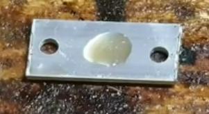 The first
trick is to put a drop of
oil on the spot to be soldered. He used motor oil but said any, even
olive oil would work. That's the flux! It keeps oxygen away from the
surface. The surface of alume oxidizes in an instant in air, a one
molecule thick layer, and that's what prevents soldering to it.
The first
trick is to put a drop of
oil on the spot to be soldered. He used motor oil but said any, even
olive oil would work. That's the flux! It keeps oxygen away from the
surface. The surface of alume oxidizes in an instant in air, a one
molecule thick layer, and that's what prevents soldering to it.
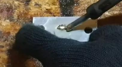 The second
trick, after getting it hot, is to rub it (quite a
bit) with the soldering iron as you tin it. This scrapes off the
existing oxide layer to expose the actual metal to the solder. After
tinning a spot on a small plate of alume and a fat stranded wire, he
soldered the wire to the plate.
The second
trick, after getting it hot, is to rub it (quite a
bit) with the soldering iron as you tin it. This scrapes off the
existing oxide layer to expose the actual metal to the solder. After
tinning a spot on a small plate of alume and a fat stranded wire, he
soldered the wire to the plate.
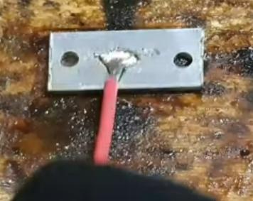 When it was
cool he pulled and twisted until the wire actually broke - the solder
joint and the ends of the wire
stayed put on the plate.
When it was
cool he pulled and twisted until the wire actually broke - the solder
joint and the ends of the wire
stayed put on the plate.
BTW in the comments some said the technique hadn't worked
for them. I suspect from what was said that they were trying to solder
anodized alume, which has a very thick layer of oxide. You would have
to sand/grind it down to the metal first. OTOH perhaps some alloys
might not work.
(I wonder if you can solder to stainless steel with this
method? or to zinc?)
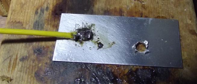 I tried it
myself, with the soldering station set to
600° and the big tip on it, and a small piece of alume. (I usually
use 400°, but I figured the Al sheet would conduct much heat away.)
Sure enough - worked great - solid join! There was
some smoke from the machine oil. Maybe olive oil next time?
I tried it
myself, with the soldering station set to
600° and the big tip on it, and a small piece of alume. (I usually
use 400°, but I figured the Al sheet would conduct much heat away.)
Sure enough - worked great - solid join! There was
some smoke from the machine oil. Maybe olive oil next time?
Another Peltier Module Heatsink
Idea
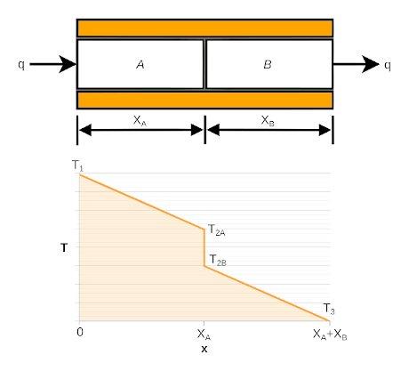 The above brings to mind, as I have noted, perhaps ad nauseum, that one
thing that degrades the
performance of Peltier modules is the loss or gain of temperature
at the junction between the body of the module and the heatsink, and
here's an
illustration I found.
The above brings to mind, as I have noted, perhaps ad nauseum, that one
thing that degrades the
performance of Peltier modules is the loss or gain of temperature
at the junction between the body of the module and the heatsink, and
here's an
illustration I found.
The closer in temperature the two sides are, the higher
the COP and the lower the heat transfer across the module. If you want
to cool a cooler by 15°, and 3° is lost on each side before the
heatsinks "T2A to T2B" times 2),
the module has to cool by 21°. That's just for starters of course.
Then there's the heat loss/gain going through the heatsinks: "T1 to
T2A" for two
heatsinks, and the final temperature of the heatsink fins (T1)
above/below the air temperature, which is mostly mitigated by fans.
To be complete the picture there's the loss/gain "T2B to
T3" from the actual components within the module to each ceramic
surface. (the Peltier manufacturer's concern!)
In my homemade "superinsulated" Peltier module fridge I was freezing
the ice tray through the copper bar (Cu = lowest junction heat gain)
and a second junction from the bar to the alume tray of water (but this
one with much more surface area than the Peltier module). The outside
"hot side" alume alloy heatsink was often around 35°. So the module
was probably about 40° between sides - with the bulk of the "extra"
5° being the module to alume alloy heatsink junction. 40° (when
you're trying to cool by only 20°!) leaves a lot of room for
improvement. Every degree counts until you've made the fan(s) too noisy
and so the unit is put aside or discarded by the user.
Now, if I could solder copper to alume over a broader
area, I could make the heatsink for Peltier modules have a lower
junction
temperature between the module and the copper section of the heatsink,
without
creating a second high thermal resistance junction where the two metals
meet. The trick would be tinning the heatsink over that large area so
the copper would thermally bond as well as just electricly.
Some had suggested in the alume soldering video's comments
putting oil
on and then wire brushing it before heating. Perhaps that would allow
tinning the required
broad area?
Here are some thermal conductivity figures I dug up
on line. (Presumably valid at or around room temperature.)
Boron arsenide (BAs): 1300
W/m*°K -- Looks tricky
Diamond: 1000 -- but can this
help us? (Graphite: 1000 'along the grain'? see comments below.)
Pure silver: 418 -- Most conductive element
Pure copper: 401 -- almost as good, cheaper, not quite as heavy
Pure Alume: 237 -- a big step down but cheaper and lighter than
copper. Soft and easily bent.
Al - 6160 T6 alloy: 167 -- the worst one - and the one usually used for
heatsinks. Another big step down. Fine for preventing transistors from
cooking. Not good for Peltier cooler COP! Substantially harder than
pure alume.
Thoughts on those best ones... We can't make a BAs or diamond heatsink.
Hmm... Diamond powder on copper? But that doesn't expand the surface
area from the Peltier module. A substance called boron arsenide (BAs)
is rated as 1300 - much more thermally conductive than any single
element! It turned out that was for a pure, flawless crystal, so unless
huge flawless crystals can be grown, like the diamond it is of little
use for peltier modules. (Unless again it could be made as a flat
powder "sheet", fused to copper.)
Looking for "boron arsenide powder", it is in fact
available. Perhaps (if it is quality crystals, however tiny) it could
be used as, or in, a heatsink compound in place of silicone compound,
flexible graphite or graphite powder, to make a better thermal
connection between the ceramic surface of the peltier and the heatsink
itself. But...
Graphite Heatsink?
Then again, graphite sheets are rated at 1000 W/m*°K
along the grain similar to diamond, although they are much lower (said
to be 1% as much?) between layers. Exactly the wrong way! Still, with
flex graphite gasket one can feel rapid heat transfer through the
thickness as if it was a metal like copper, so I think the 1% is a
mistaken or at least misleading figure at least for that material.
Anyway a thin sheet of flex graphite seems to conduct heat between
module and metal (across the grain) better than silicone heatsink
compound. (And it's not ucky!) Hmm... What about graphite sheet
heatsink fins?... could they be better than alume? or copper? and flex
graphite is really lightweight! What about a whole flex graphite
heatsink? Maybe with sideways stacked sheets bolted together so the
module's heat is going up along the grain to yield that "1000" figure?
At least in theory that could be much better even than copper! Oh dear,
this train is picking up speed... time to jump off! (For now!)
Battery Chemies
Despite having discovered several chemical "firsts" or
"bests" for batteries over the years including this latest, all my
cells are still plagued by very low current capacity. Other problems
were leaks of electrolyte and material getting around the edges of
separator sheets causing electrical paths between electrodes and
preventing them from holding their charge.
By mid month I was almost ready to think of giving up on
the possibility of making workable batteries. Voltage readings
suggested that the bottleneck was likely to be poor conductivity
through the positive electrodes. (Seemingly no matter what I made them
of!)
But there must be answers. And additional chemical
possibilities seem to be presenting themselves. So I'll persevere.
(After all, Edison spent over 30 years on battery research before he
came out with his successful alkaline nickel-iron 'pocket electrode'
batteries first in 1908 - I saw a picture of a lab note of his from
1875.)
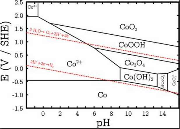
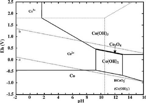 Looking at some Pourbaix diagrams I conceived that cobalt
oxyhydroxide CoOOH or "Co3O4" and Co(OH)2 could make a great electrode
- better
than nickel oxyhydroxide NiOOH. Puzzlingly (at least to me) neither of
the indicated redox reactions seemed to work. It just didn't hold the
expected charge. Is that why no one has used cobalt, or was I
doing something wrong? But the
lowest voltage reaction, between Co(OH)2 and metallic cobalt, did work.
Looking at some Pourbaix diagrams I conceived that cobalt
oxyhydroxide CoOOH or "Co3O4" and Co(OH)2 could make a great electrode
- better
than nickel oxyhydroxide NiOOH. Puzzlingly (at least to me) neither of
the indicated redox reactions seemed to work. It just didn't hold the
expected charge. Is that why no one has used cobalt, or was I
doing something wrong? But the
lowest voltage reaction, between Co(OH)2 and metallic cobalt, did work.
Cobalt-zinc cells made that way would be under a volt, but
this reaction moved two
electrons per reaction instead of one, so it was double the amp-hours
of the other two reactions together. And the metallic form should be
highly conductive for high currents. Despite the seemingly ridiculously
low
voltage, this would mean that far less cobalt was required to balance
the
zinc's amp-hours: it would take more cells to attain a given voltage
but each cell would store more energy instead of less - an overall gain
in watt-hours per kilogram.
In checking out redox
potentials of some elements I realized I could use copper powder as a
conductivity enhancement for the cobalt hydroxide electrode. With the
low reaction voltage it wouldn't turn to copper oxide and dissolve.
Could that turn tens of milliamps into amps, the required two orders of
magnitude improvement in current capacity?
The Role of pH
I tried copper chloride as a potentially better
electrolyte than potassium chloride, and discovered that it has an
acidic pH rather than neutral. One cell with no calcium hydroxide ended
up having an acidic pH and I'll have to try cobalt over again. I
finally realized (after all these years) that pH can play an important
role in making different substances and chemistries work well in a
cell. (For example the cobalt diagram above shows that cobalt oxides
should be most stable at around pH 11... although they are added to
nickel oxide cells to enhance conductivity at pH 14, which is not
intuitive.) I read up on "pH buffers". By using the basic calcium
hydroxide and acidic copper chloride, the cell's pH can be somewhat set
into a desired range and not drift too much.
Since it was discovered that nickel metal, and only
nickel, won't oxidize at pH 14, everyone went with caustic KOH
electrolyte and different pH'es for cells seems to be an almost
unstudied area of battery research.
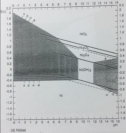 And yet, from
appearances, even nickel oxides should work better at a lower pH than
14 - eg at 10 or 11.
And yet, from
appearances, even nickel oxides should work better at a lower pH than
14 - eg at 10 or 11.
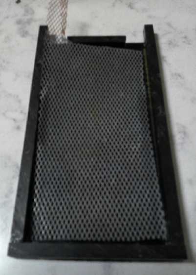
 After a couple
of different cells and chemistries with perplexing results, near the
end of the month I made a nickel-zinc cell just because I know the
combo works, and the sodium dodecylbenzenesulonate in the separator
sheet should stop zinc dendrites from sooner or later shorting out the
cell. (usually quite soon, in my experience.) Except for leaking around
the edges somewhere and having to keep adding water it continued
performing about the same for a couple of weeks after gradually
improving some during the first few days. Stability!
After a couple
of different cells and chemistries with perplexing results, near the
end of the month I made a nickel-zinc cell just because I know the
combo works, and the sodium dodecylbenzenesulonate in the separator
sheet should stop zinc dendrites from sooner or later shorting out the
cell. (usually quite soon, in my experience.) Except for leaking around
the edges somewhere and having to keep adding water it continued
performing about the same for a couple of weeks after gradually
improving some during the first few days. Stability!
 Then I decided to take it out of its ABS
case and just wrap it up with packaging tape, to cure the leak. That
seemed to get some material crossing an edge of the separator sheet
somewhere and it didn't work right after that. Sigh!
Then I decided to take it out of its ABS
case and just wrap it up with packaging tape, to cure the leak. That
seemed to get some material crossing an edge of the separator sheet
somewhere and it didn't work right after that. Sigh!
I now have in mind a design
where the separator sheets are sandwiched between two 3D printed
bevelled "bread crust" edge pieces with no solid front or back, with a
small water reservoir and filler hole incorporated at the top so one
knows if the cell is drying out and can refill it. (Hopefully not more
than every few years!) The separators can even stick out the edges a
bit instead of being precision cut. The whole will be wrapped with
packaging tape as the body of the cell. (If it leaks, add some more
tape!)
Assembly would go like this: The rear "bread crust" is set down on
packaging tape and the rear current collector is placed in the cavity
thus formed with its tab coming out an indent in the crust. Then the
electrode powder/material goes on that, making sure it doesn't cover
the top of the "crust" anywhere. Then the prepared separator sheets are
placed on top, then the top "crust" goes on to form a cavity for the
front electrode. The "crusts" should be taped or pinned together to
prevent any material from seeping in toward the edges of the separator
sheets. Then the top electrode and current collector are placed, then
it's all wrapped with the tape to seal it. The height of the edges can
be adjusted so that when the electrode materials are compacted in the
clamps, there's still a slight bulge rather than the edges limiting the
pressure on the materials.
And maybe I'll make the cells taller yet, with thin (3D
printed integral) cross braces from left to right to keep the edges
from bulging. Nothing like size and more material to boost capacity,
and that would work without making them any more complicated or making
the electrodes thicker. (If they were wider as well as taller, the 1/4
inch thick alume clamp plates would probably bulge, losing compaction
in the middle area. But "any" height should be possible.)
The whole idea of being able to clamp a cell or a set of
cells between two alume plates certainly gives freedom of design for
flat plate cells, and takes away the need for strength of the large
flat front and rear surfaces of each cell itself. (I wish I had figured
this out long ago!)
Living Titan
I finally made a start of putting back together my
"Sears.com" website after Niklas Saers, having become a computer
professional, changed the whole site to his now more mature,
professional liking and deleted all the stuff everybody else had posted
over the last 22+ years.
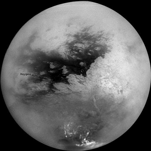 I got only as
far as a pile of editing of my work Living Titan (2005 -
2006) about what the Cassini-Huygens mission was finding on
this astonishing and previously unknown world somewhat smaller than
Mars that orbits Saturn.
I got only as
far as a pile of editing of my work Living Titan (2005 -
2006) about what the Cassini-Huygens mission was finding on
this astonishing and previously unknown world somewhat smaller than
Mars that orbits Saturn.
It's covered
with immense forests of giant trees, and with aquatic vegetation of a
scale unknown on Earth growing in the shallow tidal-flowing seas, lakes
and rivers of liquid methane. The low-rez monochrome and radar images
that were returned don't make these facts jump out at the casual
observer. I couldn't bring myself to just throw this "book"
back on line as it was in 2006, since the Cassini mission had continued
on for several more years and more exciting and revealing things were
discovered. And in editing I could correct some of my own early
mistaken or distorted impressions.
Earth life wouldn't last five minutes at Titan's
temperatures. That seemed to blind the mission's space scientists.
'It's like a deep-freeze Earth that must be how Earth was before life
started.' they kept saying like a mantra. They ignored "inconvenient"
instrument
returns that didn't fit their preconceived ideas. Somehow benzene,
amino acids, proteins and polycyclic aromatic hydrocarbons were just
organic "tholins, left over from the formation of the solar system."
They utterly misinterpreted the whole amazing scene that a few months
of study gradually opened my eyes to. Every new "mystery" that was
reported, every unexpected or "inexplicable" finding, the images and
radar returns, all fit right in with an Earthlike and yet very
different world, covered with alien vegetation. And many things in the
mission one after another besides Titan kept diverting scientists'
attention.
For a while they even claimed that Titan had no liquid methane!
Last I heard they were still saying that the shallow equatorial
seas so obvious in the images and SAR radar findings from both Cassini
and Huygens and reported by other instruments as well, are dry land!
How then could they see the totally unexpected verdant
plant life? The profuse aquatic vegetation itself explained why they
didn't see the reflections they had expected to get from open liquid. A
few emails with some of them revealed how closed-minded they were. And
I heard that they would never disagree publicly, whatever differences
they had in private.
One suspects that if there's plant life there are also
animals. But looking down on the Amazon rainforest from a distance,
does one expect to see monkeys and otters and birds? or just a forest
canopy? And I didn't see any sign of human works. The vegetation is all
I'm sure of.
Yet, for all the hours I put in this month and all the
details I added, the writing is still rather helter-skelter,
disorganized. I could spend weeks making it into a nice, well organized
book. I don't seem to have time. (Feb. 10th: I can't even seem to
finish this monthly report!)
Living Titan
In
Passing
(Miscellaneous topics, editorial comments & opinionated rants)
Scattered
Thots
*
We know that cutting down forests causes droughts. A mechanism has been
found that helps to explain this better than was previously understood.
It seems trees release "turpines" into the air. These give for example
the "fresh" smell of a pine forest. These also act as condensation
nucleation sites which help to form clouds and foster rain. In other
words, trees do their own cloud seeding. [from SciShow on Youtube.] So
the more forest is cut down, the more droughts are likely to occur.
* I had started keeping track of how much Sumatriptan I was using for
migraines, being quite susceptible to them all my adult life.
Sumatripan and occasionally Cambia have made life far more livable for
me than it used to be before they were created and somebody finally
told me about them. I was hoping one package of 6 pills per month would
be plenty. By almost the end of January I had only used 3 pills from
the December package. Then suddenly it was one migraine after another
until by February 8th I had used all 9 of the remaining December and
the January pills, sometimes half a pill, once 3 pills in two days.
They're great, but definitely not as good as simply not having a
headache.
What was it? Bad bananas? Bad cheese? Maybe the ice cream
(which package I had been eating from for months without ill effect)?
Maybe the mayonnaise had suddenly gone off? or the mustard? (I didn't
think mustard went off?) None of it seemed likely except maybe the
cheese - I had bought three small packages "on sale". I would open one
and use some then slice up the rest and put it in the freezer (with the
date [and for these, "??"] on them. I was keeping my coffee pot &
dishes clean and had a fairly new filter in the Britta pitcher. I
dumped the mayonnaise in the compost (needlessly it turns out) and
finally had stopped eating everything else on that list, and still was
getting continual headaches. What could it possibly be?
Finally it occurred to me: I was having a handful or two
of trail mix every day, just like usual except that I had opened a new
package and dumped it in the jar. I don't remember but it wasn't one I
usually bought... "Vitality Mix" or something? It had a slightly
unusual flavor. That had to be it! What in God's name could somebody
put into trail mix that would cause migraines? That odd
flavoring, no doubt. By this time I had eaten much of it. I dumped the
rest in the compost. That was one expensive little clear PETE box of
trail mix, both in terms of expense and health! The headaches stopped.
* And there is just one of many things unknowingly affecting our
health. We suffer, never suspecting the cause and sometimes die. Some
of the worst are well known, like scurvy is lack of vitamin C. Others
are known but not well known or taught in school as I think
they should be: Vitamin D cuts the chances of getting cancer at least
in half. Arthritis and osteoporosis are caused by boron deficiency.
Most thinning hair and baldness is [surely] caused by "microscopic"
Demodex Folliculorum mites on the scalp. Drinking too-hot liquids can
cause esophageal cancer (and I knew someone who always sipped boiling
hot tea while having life threatening esophageal problems and doubtless
died from it). Homogenized milk goes through blood vessel walls and can
clog arteries. (and I met someone who was proud of drinking a glass of
milk a day and who had life threatening calcium buildup in his
arteries. The doctors were about to operate... and surely all he had to
do was reduce or eliminate his milk intake!)
There are probably dozens of health things overall that
are worth learning about, except that "we don't know what it is that we
don't know" in order to find them out. And then there are the things
that would better everyone's health and lengthen our lives that just
haven't been discovered yet. They say the first person who will live
150 years is alive today. How far have medicine & health come in
150 years? By the time he is elderly still more things related to
living longer, healthier lives will be known!
* Population of Ukraine: 1990, 52 million; 2020, 44 million; 2022, 37.5
million. Millions had already fled the corruption and nazification
since the collapse of the Soviet Union and by 2022. Crimea and the
Donbass (including 1/3 of Ukraine's military) effectively split off
after the coup in 2014. Since the start
of the war another 10 million have fled mostly to avoid being drafted
into the AFU (which is considered a death sentence) and 4 million of
the population live in the Donbass, Zaparojjia and Kherson (portion
East/South of the Dnieper), which are now in Russian hands, leaving
only
an estimated 18 to 22 million in Ukraine proper.
So here's a peaceful solution: Instead of trying to win
the Eastern regions back by throwing 16 year olds and younger, and 55
year olds and older, into bloody battle against hopeless odds and
then trying to coerce the 4 million mostly Russian speakers
there to abandon their homes and flee to some other country as
refugees, just invite all the 10-20% Ukrainian speakers in those areas
to move to vacated dwellings in the rest of the country. Let the
largely Russian speaking areas join Russia or become independent, and
sign some agreement to
end the war. There must be plenty of lebensraum in most of Ukraine now!
(Of course, while Russian has been banned in Ukrainian
territory, Ukrainian language and culture is still okay in Russian
areas. So the Ukrainian inhabitants in Russian areas may not bother to
move.)
* All dressed up and nowhere to go: Russia has mobilized a large army,
said to be for a winter offensive in Ukraine "when the ground is
solidly frozen". So far I still see on the weather maps little sign of
serious cold through most of Europe including Ukraine, and it's the end
of January. Theater commander General Surovikin must be going nuts
waiting! North America is getting it instead with record cold and snow.
I suppose the Arctic is warm too. Climate chaos! (With February Europe
has finally started to cool.)
* The "College of Psychologists of Ontario" has threatened to revoke
Dr. Jordan Peterson's license to practice psychology on a matter
unrelated to that practice - essentially for expressing his personal
views on line. He often does so in response to questions people ask him
either because they respect his thoughts - or because he has become a
public figure and they want to trick him into saying or agreeing with
something that isn't what he means. But he also called into question a
government bill that he says unduly restricts freedom of speech, in
response to its enactment.
This "college" wants him to submit to "a remedial media
training course" - to be humiliated and renounce all he believes - in
order to keep his license! Why would a regulatory body want to grossly
overstep its own regulatory bounds and hence call its own legitimacy
into question? For someone who hasn't even been practicing for years?
It smacks of political motive. When people start saying
"Jordan Peterson for prime minister!" those in power feel threatened.
Discrediting our most promising leaders over some irrelevant thing
before they just might potentially become a serious political
leadership contender is an old political dirty trick. We've lost a lot
of promising, talented leaders to trumped-up "scandals". I wonder how
much officials of
the "college" were paid by the federal government (or received "in
kind")?
* And why would the CBC support such affronts with twisted words and
innuendo? The
government today funds CBC lavishly (500 million dollars... annually?)
and it asks in return that CBC speaks for the oligarchy behind the
government. It is no longer our public network. It no longer speaks
for, represents or reports fairly to Canadian citizens. Thus in the
biggest public protest in Canadian history, the truckers' convoy to
Ottawa, the CBC parroted the prime minister's line that they were a
tiny fringe group of crazy radicals,
and a remarkably peaceful and restrained demonstration was reported as
militant and threatening to the peace.
And our august prime minister says "Canadians have a right
to protest and to be heard". These are hypocritical words from someone
who turns
a
deaf ear to the grievances of a huge mass of really upset people and
uses the "Emergencies Act" (the
"War Measures Act" renamed) to break up the first protest to come his
way.
* Canada is rapidly becoming a big disappointment in the eyes of the
world. It is earning international disgust and becoming a
laughingstock. (Along with other Western nations, unfortunately.) What
happened to the Canada of the Flag Song written
when Canada first unveiled its own flag?
...
"Take your place next to those unfurled
Spread our friendship throughout the world"
... ?
* Why did Canada have no "right to bear arms" in our constitution?
There seemed to be no need - it was implicit that Canadians would want
to hunt and when required defend themselves and their domestic animals
from predators, and that government regulations were superfluous
regarding such matters.
* "Rob Words" channel on Youtube had on someone who was trying to bring
back "Anglish" as it was before 1066 when William the conquerer
introduced all
kinds
of French and Latin words. As they went through some odd and awkward
terms that were formerly used for many and various
things, I couldn't help but reflect how much English has been enriched
by those additions. And the English of today has a plethora of new
words and terms even since a century ago. And it's still growing and
changing, although computers are increasingly enforcing "the norm" as
the world adopts English as the international language and people who
are
learning it want to conform to as not be seen as ignorant. Also I note
many new terms are often the same or
very similar in every major language as the world shrinks.
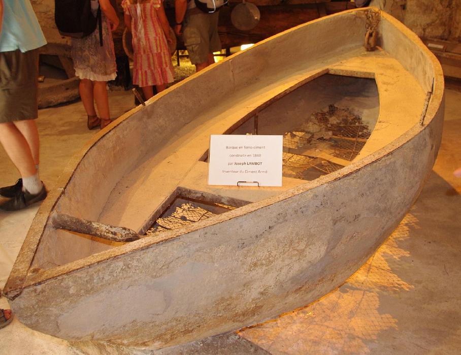 How long does a ferrocement boat
last?
How long does a ferrocement boat
last?
This is the very first one, made by the inventor Joseph Lambot, in 1848
(Okay, it doesn't look very seaworthy at this point. ...It could be
fixed!)
ESD
(Eccentric Silliness Department)
* Wheat is a flouring plant.
* I think there's a reason the words "rooster" and "roaster" are so
close together. Only the hens lay eggs.
* Is "jury rigged" the same thing as a "rigged jury"?
* OMG! If you try to type "ing" and your right hand is one key over,
you get "omg"!
"in depth reports" for
each project are below. I hope they may be useful to anyone who wants
to get into a similar project, to glean ideas for how something
might be done, as well as things that might have been tried, or just
thought
of and not tried... and even of how not to do something - why
it didn't
work or proved impractical. Sometimes they set out inventive thoughts
almost as they occur - and are the actual organization and elaboration
in writing of those thoughts. They are thus partly a diary and are not
extensively proof-read for literary perfection, consistency,
completeness and elimination of duplications before
publication. I hope they may add to the body of wisdom for other
researchers and developers to help them find more productive paths and
avoid potential pitfalls and dead ends.
Electric
Transport
Magnetic Variable Torque Converter with Planetary Gear
Bearing for Rear Drive Shaft
[15th] The 1-1/4 inch bearing came from Princess Auto. On the phone I
had hastily worked out that that was .009 inches larger than the 32mm
drive shaft. I goofed. It was the drive shaft end that was larger by
that amount. The bearing was in fact 31.75mm and it wouldn't quite go
on. Either the inside of the bearing had to be filed out (if that's
even possible) or the drive shaft end socket would have to be filed or
ground down. (Trying to turn the drive shaft on my small lathe - or
even on any lathe without disassembling it - seemed like a
non-starter.) The consolation was that if done well it would be a
better fit.
(Dang - if I'd realized, I would have ordered a real 32mm
bearing from VXB bearings. I've made more work for myself. OTOH while
on the website I discovered and got a very helpful flange mounting with
this one, which will save the work of making something up for it.)
Oh, wait! There's a protruding lip on the inside part of
the bearing. That means I should be able to mount it in the lathe chuck
and increase the inside size with a boring bar. (Assuming the metal
isn't too hard.)
[29th] I learned that friends in
Victoria have been waiting to see how my 'roadworthy' version of the
torque converter works out before potentially putting one into
(surprise) another Miles ZX40 truck! Must get back to it! I tried
fitting the wooden assembly under the truck and found that with the
rear plate on it was going to be nearly impossible to install it. I
decided it would have to do without the rear bearing I had waited weeks
for, and to do it without the whole rear plate that bearing was to
mount to. So I made a couple more cuts to the wooden side pieces, which
were blocking the motor bolts. (I had thought of using lag screws. I'd
rather not, and the bolts ended up being right at the edges of the
boards instead of somewhere in the middle.)
I still wasn't sure how I would hold up the back end of
the housing, but it would just be some sort of metal strap(s) to the
frame.
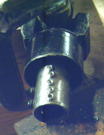
 Flat spot ground into planetary
output shaft
for 5 set screws in a row
Flat spot ground into planetary
output shaft
for 5 set screws in a row
to go through wall of [splined] socket on vehicle's rear drive shaft
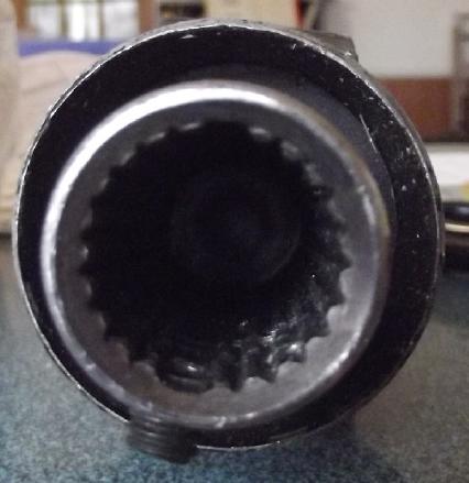 This is the drive shaft socket.
 I don't know how I can mark,
center punch and
start small pilot holes
I don't know how I can mark,
center punch and
start small pilot holes
and still end up with a crooked line. But I seem to be an expert at it.
I took the rotating
assembly (27 pounds) out to the shop
and ground a flat area into the planetary output shaft at 90° to
the shaft key. Now the key would go into one of the two wider splines
in
the rear drive shaft, and setscrews would go against the flat area to
pin it down better. I drilled and tapped for 1/4 inch setscrews. Plus
two 5/16 inch opposite from the shaft key. My
confidence that the rather thin socket metal would hold them securely
increased when it was quite hard threading in the taps, and in fact I
broke one in the process.
[30th] I went under the truck and attached the housing to the motor,
then slid the rotating assembly into place. I found the set screws ware
directly over where the shaft key had to go. Fine; like that then. With
a wooden block to prop up the back of the housing I fit the shafts
together.
I bent a 3 foot long piece of 1/8" x 1" steel strap into a
sort of a "U" with tabs on top to hold it to two threaded bolt holes
into the frame above. This went under the torque converter housing and
was bolted to the lower 2 by 6'es. I left extra length on the tabs to
make it "springy" and decouple any noise it made from the truck frame.
RIGHT to LEFT: * Curtis
AC35(?) 72 volt
motor - with splined socket shaft
* Motor end of motor-to-planetary-gear shaft (just visible) - turns sun
gear & alume disk
* Plywood wall holds bearing to steady the long shaft
* Alume rotor/disk - spins with motor
* Magnet rotor - Hallbach configuration - spins with planetary gear body
* 10:1 planetary gearbox
* Black metal "U" bracket strap holds rear end of housing up to truck
frame (Motor holds front end)
* Front end of drive shaft to rear differential, a socket fitted to
planetary's output shaft (planets assembly)
* Drive shaft, U-joint & with safety guard so if it somehow slips
off, front of drive shaft can't drop to ground.
[31st] I installed said "U". Then
I attached the video camera to the
side facing the mechanism. I ran it back and forth in the garage a
couple of times. It seemed good. With the 10 to 1 reduction plus the
magnet drive I thought it should have plenty of torque. It didn't. The
first clue was when I had to take a run to get over a little hump
coming out of the garage. I tightened the screw that couples the input
shaft inside the planetary, but I'm still not convinced it isn't
slipping. (Why do they have such a "non positive" attachment mechanism
to take all the input torque?)
I tried to drive around the driveway, but a vibration
started up whenever I pressed very hard on the pedal. Apparently the
springy back end of the housing wasn't a good idea. Then, with the
seeming low available torque the truck wouldn't go up the lumpy spots
on the lawn. Lumpy lawn is much less forgiving than smooth pavement!
Finally back backed down a bit of a slope and couldn't get up it again.
I didn't dare press too hard on the gas with the vibrations that
started. And something smelled hot. Sure enough it was the alume rotor.
When the torque converter isn't 100% efficient, the rest goes into
heating it up. I had recognized that that disk might need a heatsink.
It sure did! It was hot enough to fry french fries on. I ended up
prying the bumper forward with the peevee and kicking blocks behind the
wheels to creep it ahead to a more level spot where it would go again.
But it seemed to start vibrating more easily now and had little power.
When I swung around to get to where I could back into the garage it got
stopped again and I had to repeat the process, tho not so much uphill
or so far.
While the truck was out I swept the dusty garage floor for
the first time in ages. But it was a relief to get it safely back in. I
had expected this test to work really well. Instead I was quite
disappointed and saw there were some kinks yet to be worked out. And I
didn't leave any room between the alume plate and the bearing holder
wall for heatsinks.
Aha! On looking at the video (thank God for the "instant
replay" video looking at the mechanism!) it appears the vibration was
most likely the drive shaft slipping on the splines of the output shaft
of the planetary. No wonder there was vibration! Well, I always knew
that was the weak link. If that's the main problem (and if I can solve
it) that's actually not so bad. I can drill new holes in the drive
shaft's socket and get set screws on that flat spot I made, and maybe
I'll have to make another shaft key if that one has worn down. And
maybe the rotor won't heat up so much if everything else is working
right and the truck moves readily.
[Feb. 2nd] I pulled the rear drive shaft off. Sure enough the set
screws were no longer tight, and the shaft key was worn down from the
splines racking across it. As too often trying to make things for
vehicles, my mechanical build was too weak. It seems all too obvious
now that I should have saved the splined shaft that came out of the
transmission and fit into the rear drive shaft splined socket, to weld
onto a coupler to properly fit the planetary's output shaft. Oh well,
long gone now! (I actually checked at the yard where I discarded it,
and it's surely there somewhere, but Paul can't remember where he put
that transmission among a zillion cars and other metal things. I could
spend all day out there and still not find it.)
I'm going to put 5 set screws in a row through the socket
wall into the area I flattened on the shaft. When I have the torque
converter off again I'll grind another flat area opposite to the shaft
key slot to press the [new] key as best possible into the too-small
slot in the socket.
[Feb. 5th] I spent the day drilling and tapping the rear drive shaft
socket for 5 set screws in a row, all to cinch in to the flat side I
had made on the planetary's output shaft, then cutting and shaping a
new key to go into the too-small slot in the socket at 90° to those
screws.
After a warm-up break (after hours in the cold shop and
the woodstove had gone out while I was there), I put the drive shaft
back on the truck and did up the screws. I opened the garage door and
tried it out. But the truck's nose didn't poke out very far before I
heard some vibration. I wasn't up for another big adventure just before
dark. I backed back in and closed the door. The magnet rotor was
already slightly warm. Anyway, why didn't I have the camera on it to
see what was happening? (Oops)
[Feb. 6th] I thought the input shaft junction must now be slipping in
the planetary. I have found it to be a frustrating join because it has
only one allen screw and a clamp affair that is supposed to clamp
around the 19mm input shaft. No key slot, no splines, nothing. I
roughened up the shaft before I put it together to make it un-slippery.
How hard can one reef on a 6(?)mm screw with a vise grip on the end of
an allen wrench before something gives? How is it supposed to work?
The same vibration continued when I drove the truck out of
the garage. I didn't get very far upslope. It still wasn't right.
[Feb. 8th] I remembered there was one more component that can slip: the
alume rotor. [Duh!] The SDS taper lock hub had no shaft key. I had
tightened it pretty well, but not to the ultimate - I thought I might
want to adjust the position. I thought to go under the truck and at
least tighten its set screw - might hold it for a test or two. But it
needed a really long allen wrench. The only way to get that was to put
a magnetic bit in the "screwdriver" handle. And the magnet that held it
in wasn't nearly as strong as the rotor magnets. After a couple of
tries, and fishing out the allen bit with forceps, it got behind a
magnet. It might jam and break magnets, so I now have to remove the
whole thing to get at it. That ended any hope of having it running for
this report, even so far into February.
I then had the thought that I could have drilled a hole in
the plywood so the bolts on the SDS could be accessed and tightened
without removing it all, but now there's that allen wrench bit stuck
inside.
The perhaps more troubling problem is the alume disk
getting so hot. The whole thing should be high efficiency once the
vehicle is up to driving speeds, but at high torque at "crawl" speeds
trying to go upslope in a lumpy driveway it's much lower. And whatever
percentage loss there is mostly goes straight into heating up that disk.
I had initially realized that it might need a heatsink -
perhaps two or three finned heatsinks spinning on the back of the disk.
There was lots of space on the rotating assembly but I neglected to
make a place for them in the design of the housing. Well, possible
changes is why I didn't epoxy the whole housing solidly together yet! I
found 3 smallish heatsinks I had bought for LED COB lights. Those would
probably do it, and I think I'll be "proactive" and add them on now
rather than most likely have to re-fit it all later.
If it does get pretty warm in normal driving, something
that might be worthwhile would be to put in ducts and a fan from the
rotor space to the cab: could be good supplementary "free" heat - at
least for a windshield defrosting assist in winter?
Other "Green" & Electric Equipment Projects
Winter Gardening
Window & LED Gardening
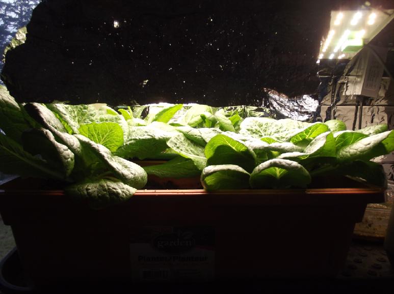 The romaine
lettuce and spinach continued to
grow well under the bright new
"100 watt" 30x45cm/12"x18" LED light dimmed down to about 35 watts (yet
still much brighter than the old ones at 40 watts each) and I got some
salad greens out of them. I finally pulled out the center lettuce plant
of the three because they were all overlapping each other. The spinach
attracted one, a few, then a zillion flying fungus gnats and I finally
plucked the spinach leaves to eat, and took it outside.
The romaine
lettuce and spinach continued to
grow well under the bright new
"100 watt" 30x45cm/12"x18" LED light dimmed down to about 35 watts (yet
still much brighter than the old ones at 40 watts each) and I got some
salad greens out of them. I finally pulled out the center lettuce plant
of the three because they were all overlapping each other. The spinach
attracted one, a few, then a zillion flying fungus gnats and I finally
plucked the spinach leaves to eat, and took it outside.
In the bay window with a few lights and very occasional
sunshine, the "third try" cherry tomato finally started producing a
little ripe fruit. (Two sets of flowers, hand pollinated, & then
tomatos... where is the next set? The "first" and "second" try tomato
plants I managed to wreck in the fall or early winter by
underwatering.)
I used up most of the ripe peppers which had started
mostly in the summer, and the plants became infested with aphids. I
wiped them off the leaves by hand now and then. The aphids spread to
the coffee plants. Hopefully when I set these all out in the spring the
aphids will vanish.
Plastic
Recycling
2.0
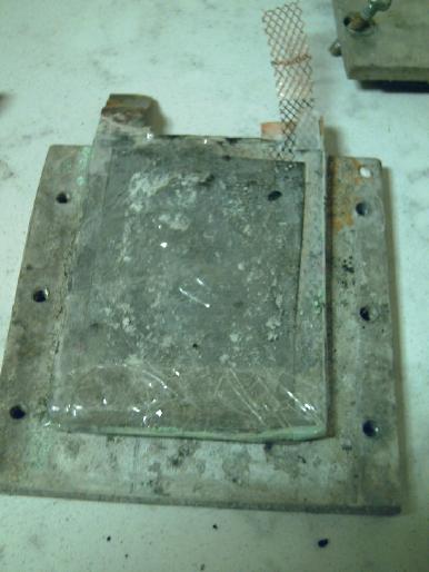
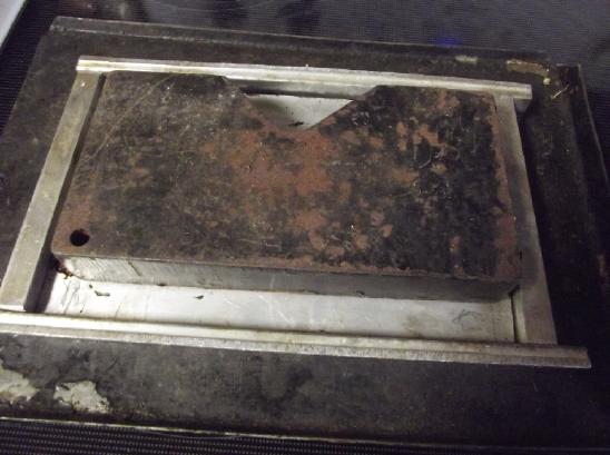
Another try melting PETE
"Sample Plate"
size alume
box mold coming out of the oven with the plastic
sagged down. 9 pound weight. On an old cookie sheet in case of
drips.
 I had long been meaning to try melting clear PETE again. I
suspected that when it had fused solidly onto the alume mold I may have
just got it too hot for its chemistry.
I had long been meaning to try melting clear PETE again. I
suspected that when it had fused solidly onto the alume mold I may have
just got it too hot for its chemistry.
I (finally) cleaned off the
little "sample sheet" box mold, repolished the plates and reassembled
it. (I found that a polishing disk and a stick of rouge polish on the
angle grinder does a really fast but not very smooth polish. I used a
polishing disk on the drill press to further smooth the surface, but it
still has grooves from the angle grinder.)
In the trials below I must note that because of the low
sides on the mold, I had to cut the "3D" shaped pieces of plastic much
too fine with scissors to get the lid below the top of the sides. The
moral is that the higher the sides are on the mold, the easier the
whole thing is. That's a key part of the idea of doing it this way:
throw big chunks of plastic in the mold instead of having to shred it.
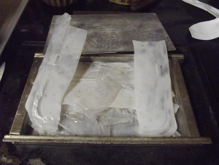 I cut some pieces of clear PETE
and put them in the mold,
and an 8 pound steel weight on top. Since it was small and I wasn't
expecting to get it too hot I just used the kitchen oven. I tried 275,
300, 325, 350, 375, 400 and 425°F. At even the lowest temperature
the crinkly pieces flattened out. Only at the highest did they even
start to melt, and at 400 and 425°F they started turning from clear
to white, and shrinking down. Yet they still didn't stick together.
Each piece was still separate. If I went to 450° would they all
melt and fuse solidly to the mold like last time? Since they had
already turned white and let much less light through, the whole point
to melting clear PETE into a sheet - to make transparent greenhouse
panels -
was already lost.
I cut some pieces of clear PETE
and put them in the mold,
and an 8 pound steel weight on top. Since it was small and I wasn't
expecting to get it too hot I just used the kitchen oven. I tried 275,
300, 325, 350, 375, 400 and 425°F. At even the lowest temperature
the crinkly pieces flattened out. Only at the highest did they even
start to melt, and at 400 and 425°F they started turning from clear
to white, and shrinking down. Yet they still didn't stick together.
Each piece was still separate. If I went to 450° would they all
melt and fuse solidly to the mold like last time? Since they had
already turned white and let much less light through, the whole point
to melting clear PETE into a sheet - to make transparent greenhouse
panels -
was already lost.
So I decided it would be relatively pointless to continue
even if it did make a nice white sheet that wasn't stuck to the mold.
It took so long to fix up the mold that I had put it off for months and
months and I was reluctant to risk a repeat. I suppose I should have
tried anyway. They're not completely opaque. Yet.
But later I tried 475°, with no better results - every
piece was shrunk and sagged flat, but still separate. And turning white.
If they didn't stay at least reasonably clear, the whole
idea of using it for greenhouse panels wasn't viable, so there seemed
no point continuing.
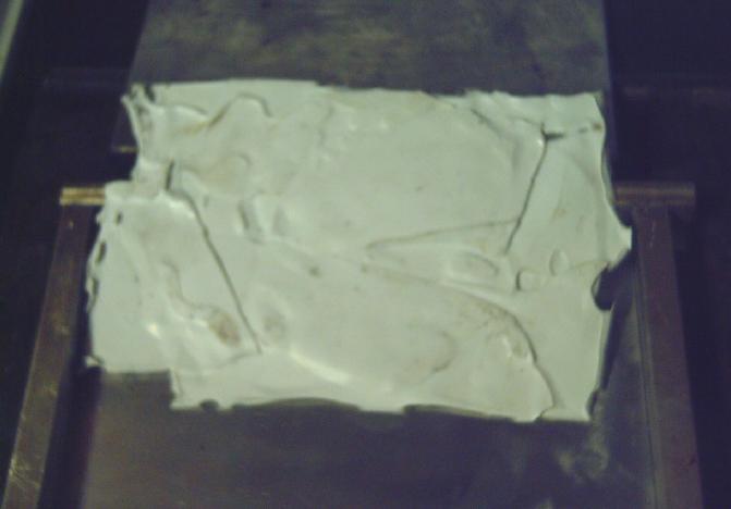 Then I tried a polyethylene
bleach bottle, warmer and warmer, finally at 500°. It was somewhat
better than the PETE - at least the pieces were fusing together. 1/2 an
hour instead of just 5 minutes probably would have made it into a
single sheet. Needs more time! - a lesson I keep relearning about
melting plastic.
Then I tried a polyethylene
bleach bottle, warmer and warmer, finally at 500°. It was somewhat
better than the PETE - at least the pieces were fusing together. 1/2 an
hour instead of just 5 minutes probably would have made it into a
single sheet. Needs more time! - a lesson I keep relearning about
melting plastic.
This was in the kitchen oven indoors, but I didn't notice
any smell.
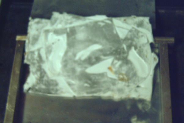 The bottom side picked up
polishing compound
from repolishing the mold surfaces.
The bottom side picked up
polishing compound
from repolishing the mold surfaces.
Electricity
Storage
New Chemistry Batteries: Cobalt Oxide Positive Electrode
Cobalt Oxides Electrode Theoretical Discussion & More Electrode
Theory
I could find no references on line to cobalt oxide
electrodes except in connection with lithium ion batteries,
supercapacitors or sodium ion batteries. Has no one ever tried cobalt
for a regular alkaline or salt battery before? Maybe any rare
references were obscured by the oodles of hits related to
those other three topics? It isn't mentioned in the "definitive" book, Alkaline
Storage
Batteries (1969) which covers battery history as well as
then present chemistries. No one, apparently, has ever done
"cobalt-zinc", "cobalt-iron" etc, or "cobalt-metal hydride".
Perhaps because it superficially looks so much like nickel oxides
but with lower reaction voltage and higher price, it's readily
passed over by the researcher?
What about conductivity? CoOOH (= Co2O3) is often used to
raise the conductivity of NiOOH electrodes. It must be pretty
conductive to be so employed in spite of its extra weight lowering the
effective amp-hours of the nickel oxide. But one source said the Co3O4
form (or is it Co(OH)2:CoOOH?) was a "poor conductor". This is at least
better than manganese where Mn2O3 (or Mn(OH)3) is "an insulator" and so
won't recharge properly to MnO2. I found no clues about Co(OH)2. One
suspects it's the most conductive form since it is the least oxidized,
but then that manganese, Mn2O3 or MnOOH (valence 3), was an insulator
when the other
forms aren't certainly caught me by off guard and I didn't understand
my "won't recharge" problem. (Otherwise MnO2 would be the simple and
cheap "+" electrode.)
NiOOH loses 2/3 of its theoretical amp-hours mostly
because of its low conductivity. For CoOOH to have high conductivity
means that with (eg) just 5% graphite conductivity additive, the
transition
CoOOH to "Co2O3" form (probably in water actually Co(OH)2:CoOOH) has in
effect almost as many amp-hours. Then the further transition to all
Co(OH)2 doubles that, so with (surely) almost three times
the amp-hours per kilogram cobalt should yield a much higher energy
density than nickel in spite of lower voltage.
And what is the voltage or voltages?
Every source of redox chemistry said something different, so I didn't
know for
sure what voltage to expect, and I didn't know if there would be a
serious step or steep slope in voltage as it charged through Co(OH)2 to
Co3O4 and then
from Co3O4 to CoOOH.
 The most optimistic forecast was
the CRC
diagram showing +.42V going valence 2 to 3. This is the one that
recently struck me while "idly" going through diagrams for different
elements one more time for some reason, and started me considering
cobalt. It suddenly
looked to me too good to be true, and sure enough it's an
oversimplification, ignoring the mixed 2-2/3 valence state "Co3O4".
The most optimistic forecast was
the CRC
diagram showing +.42V going valence 2 to 3. This is the one that
recently struck me while "idly" going through diagrams for different
elements one more time for some reason, and started me considering
cobalt. It suddenly
looked to me too good to be true, and sure enough it's an
oversimplification, ignoring the mixed 2-2/3 valence state "Co3O4".
If the zinc was -1.20V, the
cell should be 1.62 volts according to this. (Of course these are never
exact figures - as shown by the fact that a low charged cell has a
lower voltage than with a full charge, and of course the voltage drops
when drawing current.)
But the CRC charts are pretty old and not really done
thoroughly. The Pourbaix diagrams are better, but even they are made
under varying conditions and concentrations for various purposes and
don't necessarily agree with each other, as seen below.
I'm quite certain that the cell would bubble oxygen before
the valence state of the cobalt was 4 to make CoO2, even with any
overvoltage raising additives that might be found. And the CRC's +.7V
becomes +1.0V (@pH12.7) in one Pourbaix diagram (below) and just
"doesn't happen" in the other.
Half a volt in the 'plus' direction in
an alkaline environment seems to be about the limit. The dotted lines
in the Pourbaix diagrams show the potentials where oxygen (+) and
hydrogen (-) can start bubbling out of the water. The limits can be
stretched depending on the substance, and further with overvoltage
additives, but only so far. Well known nickel oxyhydroxide (+.49V
@pH14) self-discharges above 40°C if there are no oxygen
overvoltage raising additives with it. (In fact I tried charging the
first Co-Zn cell using 2.15 volts and there was no sign of it staying
anywhere up
there once taken off charge.)
Continuing on the subject, zinc stretches the limits in
the negative direction but does hold a charge. A hydrogen overvoltage
raising additive helps it not bubble hydrogen when under charge. (I'm
using a little ZrSiO4, painted onto the electrode a
parchment paper separator.) Manganese (as fine powder) stretches the
limits even further and it won't retain its charge and metallic form
without some good overvoltage raisers. (I found mixing in 1% Sb2S3, 3%
ZrSiO4 powders works.)
I thought the one Pourbaix
diagram showing both reactions at about +.25V was more likely to be
correct or closer. That would make the cell about +.25 - -1.20 = 1.45
volts.
 Less desirable would be if it
works like in this diagram, which shows the first reaction at around
-.2V and the second at +.35 (at pH 12.7). If it worked like this, there
would be a 'step' or at least a steep slope in voltage during charge
and discharge. If the cell was less than 2/3 charged voltage might be
around:
Less desirable would be if it
works like in this diagram, which shows the first reaction at around
-.2V and the second at +.35 (at pH 12.7). If it worked like this, there
would be a 'step' or at least a steep slope in voltage during charge
and discharge. If the cell was less than 2/3 charged voltage might be
around:
-.2V - -1.20V = 1.00V
If more than 2/3 charged, it would be closer to:
+.35V - -1.20V = 1.55V
These might be similar enough for motors and electronics to cope with
the changing voltages, but it certainly wouldn't be very desirable.
OTOH if the cobalt yields anything like its full amp-hours, it's got
almost as many amp-hours as nickel oxides at the higher voltage, and
then as much again at the lower. And a simple voltmeter will certainly
show when a battery is getting low!
There is yet one more
possibility: The transition from Co(OH)2 to Co metal at around -.65V.
This is a double change in valence from +2 to 0, so the theoretical
amp-hours per kilogram is doubled to 576. Considering the cobalt alone
it reaches 910 AH/Kg. If in practice it attains 2/3 of 576 it's still 4
times the effective amp-hours of nickel. But the cell voltage with zinc
would only be:
-.65 - -1.2 = .55V. That seems pretty crazy to me. OTOH the
amp-hours is huge.
Zinc is all but free. However it works, if cobalt oxides
are 1-1/2 times as expensive as nickel oxides, but less than 1/2 as
much is required to obtain the same energy, it is not only going to
make higher energy density per weight but the cost per unit of energy
will actually be lower.
On another note, cobalt is quite toxic. Precautions should
be taken not to breathe the dust or get it on your skin or in your
eyes. It is also toxic to aquatic life. (So is zinc.)
Experiment
I had been getting things ready for the new cobalt-zinc
cell.
The Cobalt Oxides Mix
- 46.5g CoO and or Co3O4 and or Co2O3(?) (93% cobalt oxide active
redox ingredient)
- 2.5g CCB (5% conductivity raiser)
- 1.0g Sm2O3 (2% oxygen overvoltage raiser)
On the 8th I assembled everything. I put 15 grams of the
cobalt oxide mix into/onto a graphite felt. (Less went in than sat on
top.) If this gives 200 AH/Kg that should be 3 amp-hours. The mix might
up to 268 (theoretical @ 93% cobalt oxides), which would be 4.0 AH.
(This is far better than the effective 90 AH/Kg for nickel, NiOOH.)
I painted the deerskin heavily with SDBS in water. It
absorbed a lot of it. I was very excited to see the cell work and
neglected to add the osmium dopant and the zircon hydrogen overvoltage
raising layer to the zinc, and to paint the cupro-nickel with calcium
oxide on the plus side. Anyway I will be able then to first check the
performance without it, and later paint it on and see what happens with
it.
I took the old (nickel manganates "+") cell out of the
clamp set and bolted the new one in.
Initial voltage was 1.046V.
I started charging at 1.75V through 10Ω at 40 or 50 mA. Soon the
current was below 15mA and I switched to 1Ω. After a while the current
was again down and I raised the charge voltage to 1.85V. Then I
squirted in a bit more electrolyte and the cell voltage dropped below
1.8
and the currents went up. It went quite a while at 1.798V and 40mA.
I was thinking nothing needed to change except the cobalt to higher
oxides, but in fact there was bound to be oxidation of the cupro-nickel
- especially without the calcium oxide on it.
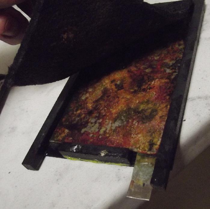
In the evening I opened the cell.
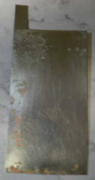 I painted
Ca(OH)2 onto the cupro-nickel, which by now had a couple of spots that
looked like bare copper. Not to worry there's still more nickel inside
the sheet. (Picture before painting.) The fact that there were only odd
spots like that wouldn't seem to say much for the connection between
the graphite felt and the metal sheet.
I painted
Ca(OH)2 onto the cupro-nickel, which by now had a couple of spots that
looked like bare copper. Not to worry there's still more nickel inside
the sheet. (Picture before painting.) The fact that there were only odd
spots like that wouldn't seem to say much for the connection between
the graphite felt and the metal sheet.
(Why can't I get, for love nor money, a camera that focuses? A
gift camera, 45$ and now 95$ down the tubes for this newest blurry
wonder. Sigh! Back to my 2005 Radio Shack video/camera with the tiny
half dead display and 3-place manual focus setting 'switch'.
[9th] Yay, a great Fuji camera that takes marvelous pictures - and
simple Ni-MH 4x "AA" cells - from the Thrift shop for 2$! Hmm...
Actually it wants 3 Ni-MH cells and at least one Ni-Zn cell, or it says
"low batteries" and shuts off just a day after cells were fresh
charged. Still, it works!)
 Then I painted the osmium doped
layer onto the "expanded copper mesh" zinc electrode and let it dry.
(Again a "before" image.) I thought I saw the fine osmium powder at the
bottom of the little test tube when I started and I put the stopper on
it and shook it up 3 or 4 times to mix it in while I was brushing it
on. Osmium is after all the densest of all elements.
Then I painted the osmium doped
layer onto the "expanded copper mesh" zinc electrode and let it dry.
(Again a "before" image.) I thought I saw the fine osmium powder at the
bottom of the little test tube when I started and I put the stopper on
it and shook it up 3 or 4 times to mix it in while I was brushing it
on. Osmium is after all the densest of all elements.
It didn't look much
different until I painted on the zirconium silicate to raise the
hydrogen overvoltage. When that was dry (image) I reassembled the cell.
Before the treatments when I short circuited the cell
through the ampmeter leeds a couple of times, it hardly supplied 1.5
amps, and the next reading (after 1/2(?) a second) was 1 amp, then
under 1. I hoped for improvement with the osmium but afterward it
seemed no better. Why do just my cells have such abyssmal
current capacity. I have never heard of such poor performance from
water based cells as mine seem to always have.
I upped the charge voltage to 2.0 volts in case it was
really not getting enough charge. Then to 2.15 before bed. It was
drawing well over 100mA, and still 70 by morning. Headed for an
amp-hour of charge
overnight? Out of 3 or 4? That should in theory be 1/4 charged.
[9th] I disconnected the charge and let the voltage drop. It finally
started definitely slowing at around 1.3 volts, suggesting (considering
it's only 1/4 to 1/3 charged) that the upper Pourbaix diagram is the
operative one or at least the closest. Then I ran a load test for an
hour with a very light load (60Ω). It started just below 1.2V after 30
seconds, was at 1.1V in 15 minutes, and hit 1.046V after an hour. In
the last half hour it was dropping a little over a millivolt per
minute. It never seemed to stop dropping anywhere, but it probably
would have if I had let it run longer. Afterward it only recovered to
1.111V in 30 seconds, and 1.160V in 10 minutes. These fairly steady but
low voltage readings throughout suggest that the lower chart is more
correct, and that the cell is running in the lower region. More
charging will tell if it will rise up to the upper voltage level or
not. I put it back on charge at 1.85V with no series resistor.
[10th] The voltages started higher in a load test but after 1/2 an hour
were a bit lower than the previous. I suspect conductivity, already
poor, has dropped.
Cell Design
The ABS cell shells seem like a good design, but
they have a flaw or two. One is that they have weight and bulk - fairly
trivial. The other is that with the solid edge walls, one can only
clamp them flat to a certain extent. Unless there's just the right
amount of material inside, the powders will be compressed too little or
alternatively the cell will leak around the edges. Furthermore there's
no way to tell how compressed it is.
I'm leaning toward modifying the design - maybe even just
wrapping up the electrodes with packaging tape.
Another way to infuse powder into the graphite felt?
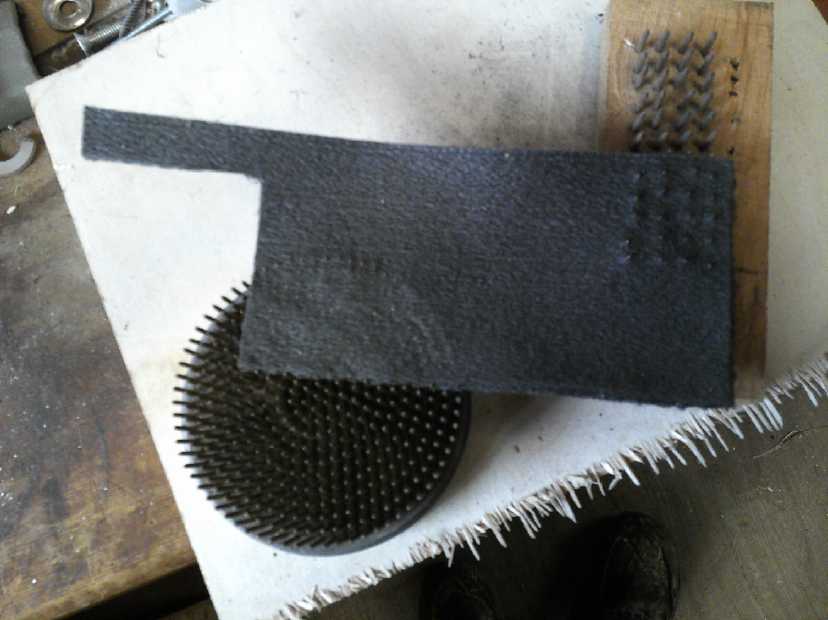 I got another
idea related to conductivity: It was hard to
get powder, however fine, to go into the conductive graphite felt.
Porous as it is, the surfaces seem made to prevent penetration.
Vibrating it in had worked rather poorly and spread a lot of dust, and
cobalt is toxic - I don't want it floating in the air even outdoors.
Putting the powder on top of the felt seemed like mostly a waste of
time, even if a certain amount did rub in. I had tried to punch some
holes in the felt with a pin frog (used in flower arranging) for the
powder to go into, but they seemed to just close up again. How about
putting the powder on the felt and then punching it in with a pin frog?
Surely that should infuse a fair quantity within the felt and very
close to the conductive fibers? (And could I dampen it first so it
wouldn't raise dust?)
I got another
idea related to conductivity: It was hard to
get powder, however fine, to go into the conductive graphite felt.
Porous as it is, the surfaces seem made to prevent penetration.
Vibrating it in had worked rather poorly and spread a lot of dust, and
cobalt is toxic - I don't want it floating in the air even outdoors.
Putting the powder on top of the felt seemed like mostly a waste of
time, even if a certain amount did rub in. I had tried to punch some
holes in the felt with a pin frog (used in flower arranging) for the
powder to go into, but they seemed to just close up again. How about
putting the powder on the felt and then punching it in with a pin frog?
Surely that should infuse a fair quantity within the felt and very
close to the conductive fibers? (And could I dampen it first so it
wouldn't raise dust?)
 I took the
cell apart and measured the conductance of the
"+"ode. I "knew" that as it was damp I would get the ionic conductivity
rather than the electronic conductivity. I "knew" I would have to dry
out the electrode to measure its real electronic conductivity, which
was too much hassle. But I touched one electrode to the cupro-nickel
terminal tab. It was hundreds of ohms! Of course: the terminal was dry!
As long as one test leed is dry only electronic conductivity is
being measured. (Well, duh!) Now... graphite felt, metal. Where was the
high resistance? Now clued in after all these years, I touched another
piece of (dry) graphite felt to the electrode. 0 ohms.
I took the
cell apart and measured the conductance of the
"+"ode. I "knew" that as it was damp I would get the ionic conductivity
rather than the electronic conductivity. I "knew" I would have to dry
out the electrode to measure its real electronic conductivity, which
was too much hassle. But I touched one electrode to the cupro-nickel
terminal tab. It was hundreds of ohms! Of course: the terminal was dry!
As long as one test leed is dry only electronic conductivity is
being measured. (Well, duh!) Now... graphite felt, metal. Where was the
high resistance? Now clued in after all these years, I touched another
piece of (dry) graphite felt to the electrode. 0 ohms.
I lifted the graphite felt electrode off the metal and saw
all the oxidation. I thought copper oxide was conductive?
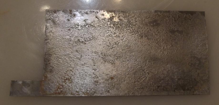 I took out
the metal and scrubbed it off with scotchbrite. It looked like clean
but pitted nickel again. I thought I had tried nickel alone before and
it had corroded. Maybe it still needed the copper inside and the fine
alloy was at the surface? I put the electrode back together and
measured 0 ohms.
I took out
the metal and scrubbed it off with scotchbrite. It looked like clean
but pitted nickel again. I thought I had tried nickel alone before and
it had corroded. Maybe it still needed the copper inside and the fine
alloy was at the surface? I put the electrode back together and
measured 0 ohms.
Then I used the pin frog and pushed it in all over to try
and get the cobalt oxides well into the felt.
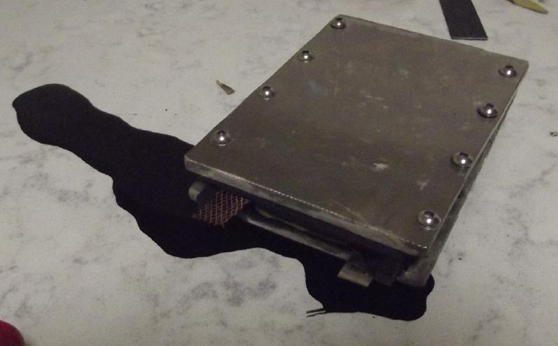 With high
hopes for high currents I reassembled
the cell.
But it had gone down to 3/4 amp short circuit current and now -- it was
no better at all! Then I realized I could access the edge of the felt
through the "+" terminal hole. But touching a piece of metal or felt
there as a contact was no help. The regular one was a little better.
Apparently none of that was the problem at all.
With high
hopes for high currents I reassembled
the cell.
But it had gone down to 3/4 amp short circuit current and now -- it was
no better at all! Then I realized I could access the edge of the felt
through the "+" terminal hole. But touching a piece of metal or felt
there as a contact was no help. The regular one was a little better.
Apparently none of that was the problem at all.
Then I thought, that when open the cell had felt like it
was thinner than the edge walls were high. I could press it all down
below the edges of the walls by hand before I put the cover on. Take
apart again!... I cut a couple of pieces of plastic for spacers and put
them atop the zinc 'trode. When I screwed the cell together again pools
of black water oozed out, converged and ran across the counter. There
shouldn't have been room in it for so much liquid. Now the sponge was
being squeezed.
Finally the performance was
a little better. It was back
to 1-1/2 amps short circuit current, and it drew more charging current
at a lower supply voltage (1.8V, 80mA). Could I squeeze in another
plastic spacer? Worth trying! But overnight it virtually stopped
drawing current and I raised the charge to 1.9V to get it flowing
again. For a cell that most optimisticly was 1.6 volts? Hmm, again
"absurdly" high charging voltages, just like with the
nickel-manganates. It must be a "feature" of the low cell
conductivities.
[11th] I had had the fleeting thought that the copper mesh didn't seem
to be as good a base for the zinc as the solid copper foil sheet. The
plating current in the zinc chloride had been 1 amp instead of having
to limit
it to 3. And now the current drives in the cell are lower than with the
previous cell. Could the metallic zinc electrode be the
problem? The metallic zinc is internally highly conductive. But it's a
flat sheet, presenting minimum surface area to the electrolyte for its
96 square centimeters size. And the expanded mesh seemed (from the
plating current) to have reduced rather than increased it.
But a 'standard' non-alkaline "D" cell also has a flat sheet of
zinc as a "can" around it and will put out around 8 amps shorted. It
has 1/2 the zinc surface area of my cells. Why don't mine put out 16
amps? Let's see...
1. The deerskin is a lot thicker than the dry cell separator sheet.
2. In the dry cell, the zinc dissolves into the electrolyte at the
lower pH? That means the zinc sheet is always "clean" zinc metal
contacting with the electrolyte? in mine, the zinc forms an oxide on
the surface, reducing access to the metallic zinc behind. Ah, of
course. That's why in alkaline batteries with zinc, the negode
is a paste of zinc powders and KOH, rather than a sheet.
The previous cell was open... I put its zinc electrode
into the new cell. It was thicker (with a piece of paper stuck to one
side) so a thicker piece of plastic to compress the "+" powder/graphite
felt electrode better wasn't needed.
The short circuit current went up to just under 2 amps.
Not a lot. Maybe I needed to toally re-think how I did the zinc
electrode. Instead of a flat, plated-on sheet, it needed to be a
powder/paste electrode, like the zinc paste electrodes in the center of
alkaline dry cells?
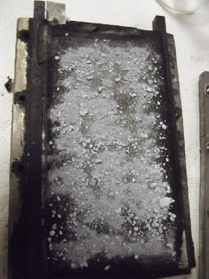 So I opened
things up again. I found a small jar labeled
"Zinc powder - Grinder". I must have made that before I knew where to
get zinc powder. That would be coarser, more granular than the zinc
nano-powders I had bought. A mix might be good, but I was leery of the
nano powder and nano flakes, which were so fine they could virtually
fuse into a sheet under pressure. So I mixed in 4 grams of the
"Grinder" powder (which seemed to be more zinc oxide than zinc) and
sprinkled it onto the separator sheet. Then I put the expanded mesh
electrode on top, a plastic spacer, and closed the cell. It was under 1
volt. I don't know why, but every time I open a cell, when I close it
it completely needs recharging again. I added some electrolyte and a
small chunk of copper chloride (made from HCL + CuO), put it on charge
and after a bit took
it off and shorted the cell. Half an amp - worst yet. Rats! I
considered that the powder pushed the grill away from the separator.
and so it might be lower. I should have put in the grille (which after
all is full of holes) and then sprinkled the powder on top of it so the
grille was squarely against the separator.
So I opened
things up again. I found a small jar labeled
"Zinc powder - Grinder". I must have made that before I knew where to
get zinc powder. That would be coarser, more granular than the zinc
nano-powders I had bought. A mix might be good, but I was leery of the
nano powder and nano flakes, which were so fine they could virtually
fuse into a sheet under pressure. So I mixed in 4 grams of the
"Grinder" powder (which seemed to be more zinc oxide than zinc) and
sprinkled it onto the separator sheet. Then I put the expanded mesh
electrode on top, a plastic spacer, and closed the cell. It was under 1
volt. I don't know why, but every time I open a cell, when I close it
it completely needs recharging again. I added some electrolyte and a
small chunk of copper chloride (made from HCL + CuO), put it on charge
and after a bit took
it off and shorted the cell. Half an amp - worst yet. Rats! I
considered that the powder pushed the grill away from the separator.
and so it might be lower. I should have put in the grille (which after
all is full of holes) and then sprinkled the powder on top of it so the
grille was squarely against the separator.
And if the electrode(s) wasn't touching the moist
separator sheet, the cell had to be filled with water to work. When I
squirted in water the charging current jumped way up (~~150mA, then
climbed down again) and the short circuit current went up to 1.7 amps.
A lot of bubbling was occurring as I left it on charge. I
assume these are oxygen bubbles as the zinc oxide charges to zinc.
Maybe in the morning the currents will be higher?
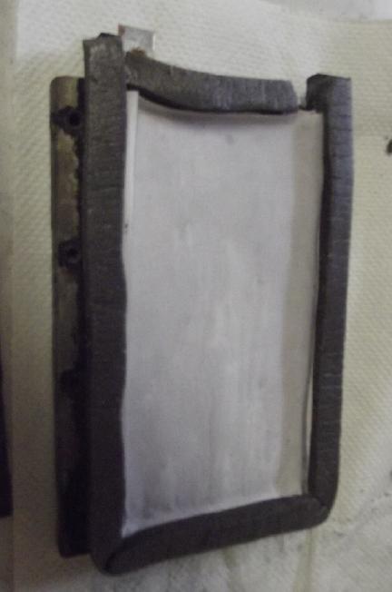 In the meantime I had been
wondering how to make cells
that would compact as needed for whatever thickness the electrodes
happened to work out to, without the edges bulging out uncontrolled. I
bought some sponge rubber trip. Perhaps there could be a thin
lower wall of ABS of about the thickness of the lower electrode. Then
the separator could go on to the outside edges of the walls.
The rubber wall would go on top of the separator with the upper
electrode inside, then the whole thing would be wrapped in packaging
tape to waterproof it. As the separator would extend beyond the
electrodes on all sides, there would be almost no chance of a gap. The
edges would be thinner than the internals when pressed together, so
they wouldn't prevent proper compaction of the electrodes.
In the meantime I had been
wondering how to make cells
that would compact as needed for whatever thickness the electrodes
happened to work out to, without the edges bulging out uncontrolled. I
bought some sponge rubber trip. Perhaps there could be a thin
lower wall of ABS of about the thickness of the lower electrode. Then
the separator could go on to the outside edges of the walls.
The rubber wall would go on top of the separator with the upper
electrode inside, then the whole thing would be wrapped in packaging
tape to waterproof it. As the separator would extend beyond the
electrodes on all sides, there would be almost no chance of a gap. The
edges would be thinner than the internals when pressed together, so
they wouldn't prevent proper compaction of the electrodes.
Well, something like that, anyway. In the context of the
present cells, some around the edges and then a piece of ABS on the
front instead of the gasket rubber. (It's lighter anyway.)
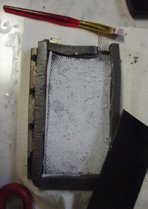 [12th] I don't seem to have solved the low
currents in this cell, but
perhaps I've solved them in principle. I need to get some coarse/mixed
size zinc powder. Actually, I can probably use some I've saved from
disassembling alkaline 'D' dry cells. Those should be ideal. I found
the jar and found inside they were 'totally' turned to zinc oxide. They
were still unprocessed, highly alkaline, so I went about diluting out
the KOH with several dilutings. The first one was tap water, after that
distilled or "reverse osmosis" purified. I hope they will work okay
once recharged.
[12th] I don't seem to have solved the low
currents in this cell, but
perhaps I've solved them in principle. I need to get some coarse/mixed
size zinc powder. Actually, I can probably use some I've saved from
disassembling alkaline 'D' dry cells. Those should be ideal. I found
the jar and found inside they were 'totally' turned to zinc oxide. They
were still unprocessed, highly alkaline, so I went about diluting out
the KOH with several dilutings. The first one was tap water, after that
distilled or "reverse osmosis" purified. I hope they will work okay
once recharged.
The "www" (the "hextupleyoo") said alkaline zinc
electrodes were in "a gel" with KOH. The gel was never specified on any
web site. (PVA?) The zinc probably needs nothing in the flat cell
except the current collector. The copper mesh is probably the best.
Does it need to be plated with zinc if the zinc is in particles all
around it? A few more particles instead, maybe? And it might plate
itself in charging and discharging the cell, and hence be a superfluous
step?
But what about the osmium
film and the zircon? To coat a
zillion micro zinc particles would take a lot of the rare element, and
the zircon is an insulator. (Hmm, could it be my low currents problem?)
I decided to put in a piece of parchment paper with the Os painted on
one side and the Zr on the other, between the zinc and the separator
sheet. The main separator would only have the sulfonate. I put the Oz
on the zinc side and the Zr against the main separator.
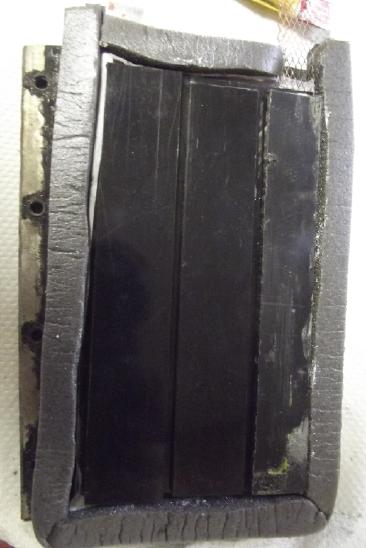 I took the
cell apart. I took out the deerskin separator.
Whatever its physical properties, it's not dimensionally stable. I cut
it straight and it shrinks and has a diagonal edge. I painted sulfonate
on a paper that had a "V" (varsoled) on it and used that. Then I cut
and painted the parchment and put it on top. I cleaned off the zinced
copper grille and set that in place. Then I put in 10 grams of the
gritty dry cell zinc paste and spread it around the grille. I tried to
hold the grille against the paper, but I'm not sure how successful I
was.Then I pasted down a 3/8 inch wide strip of the sponge rubber
weatherstrip. I put in ABS plastic spacer pieces until I was sure the
screws would be clamping the plates down on the electrodes, not the
solid ABS edge of the cell. I put the same piece of rubber on top for
the front. I did up the clamps pretty tight, but not as tightly as I
could. (Sigh, it leaks. Somehow not a surprise.)
I took the
cell apart. I took out the deerskin separator.
Whatever its physical properties, it's not dimensionally stable. I cut
it straight and it shrinks and has a diagonal edge. I painted sulfonate
on a paper that had a "V" (varsoled) on it and used that. Then I cut
and painted the parchment and put it on top. I cleaned off the zinced
copper grille and set that in place. Then I put in 10 grams of the
gritty dry cell zinc paste and spread it around the grille. I tried to
hold the grille against the paper, but I'm not sure how successful I
was.Then I pasted down a 3/8 inch wide strip of the sponge rubber
weatherstrip. I put in ABS plastic spacer pieces until I was sure the
screws would be clamping the plates down on the electrodes, not the
solid ABS edge of the cell. I put the same piece of rubber on top for
the front. I did up the clamps pretty tight, but not as tightly as I
could. (Sigh, it leaks. Somehow not a surprise.)
As usual the cell was under
1 volt when it was
reconnected. Now, what would an hour or two's charging do? The charging
current seemed no better than usual. I did the clamps up much tighter
and it went from 45mA to over 60mA. It needs an order of magnitude
improvement and I'm able to get 33%?
Why am I doing salt electrolyte again? Oh, ya... it's
safer and should allow different element chemistries or variations from
alkali.
But somehow it seems so much easier to get high currents with KOH
alkali.
And yet, 'standard' dry cells do pretty well. Plating zinc in zinc
chloride salt can have lots of current. What is it, then?
I fed in a couple more chunks of CuCl2 salt into the hole
by the mesh electrode. After the first one the charging current went up
quite a bit. On the second one it went down. Huh? Later it was way up -
the mesh terminal was bent over a bit and touching the other electrode.
grr! I bent it back and it started charging again.
[13th] All the load tests were still disappointing. The voltages just
dropped and dropped by the minute without stabilizing anywhere. They
didn't last 20 minutes in spite of the very light 60 ohm load. I think
all the higher voltages were from the nickel content on the surface of
the current collector sheet, charged to NiOOH with the 1.9 volt charge.
I had been stopping the discharge tests at about 1 volt. If cobalt
didn't deliver at any voltage CoOOH => Co3O4 or Co3O4 => Co(OH)2,
that would certainly explain why no one has used it. It doesn't explain
to me why it doesn't seem to work, but if they won't charge up
it explains the frustratingly low charging currents.
One last thing to try was to see if the reaction Co(OH)2
<=> Co [metal] @~ -.65V worked. That seemed almost as useful for
a negative electrode as a positive. It would mean the cell would be
only around -.65 - -1.2 = .55 volts. Seemed a little silly... would it
work? The next test had the usual ever-dropping voltages but I kept it
going. At around .65V [& 35 minutes in] the rate of descent dropped
sharply. By .602V it stopped dropping. It hit .601V but by the end of
two hours had risen to .603V again. There it was. It was working like a
real battery, at whatever ridiculous voltage.
There's compensation for the low voltage: 576 amp-hours
per kilogram instead of 288, from the two-state change in valence -
over 6 times as much theoretical as NiOOH gives in practice. (Maybe in
practice 4 or 5 times?) My 15 grams of Co(OH)2+graphite+Sm(OH)3
substance should be holding 8.0 amp-hours of charge! The 10 grams of
zinc should be 8.2 AH. My cell therefore should have 8 amp-hours of
charge. Even at only .55 volts that's 4.4 watt-hours. Considering the
powders only and not the current collectors or the housing (or the
heavy alume clamp plates), that's 4.4WH/.025Kg=176 WH/Kg. A 'D' cell of
140 grams would hold around 25 watt-hours of energy, which is about
equal to Mn-Zn alkaline non-rechargeable at 22.5 WH [similar weight],
or over double Ni-MH at 12WH [165 grams]. It's definitely way "up
there" in the higher "specific energy" (energy per weight) category.
And, whatever the theoretical charts say, the actual
voltage during discharge of .6 to .67 volts in my first experiment
seems a little higher (albeit with a very light load and well charged).
And if the electrode had higher conductivity it might be a little
higher yet. With no load the cell sits at a little over .82 volts. .66V
under load is 20% more energy than .55V. If the voltage can be rated
there, that would be 5.28 watt hours or 211 WH/Kg and all but 30
watt-hours for the 140 gram 'D' cell. That would be phenomenal! (And
owing to the much lesser amount of positive electrode material needed
to balance the negative, substantially more total redox potential might
be crammed into, say, a 185 gram 'D' cell to give it 40 watt-hours!)
3 Next Questions
The next questions: would it supply more current? and,
would it recharge? and, was there any other element that one could use
the transition from oxide to metal with and get higher energy - or at
least a higher voltage?
Trying to get more current
I started with "more current?" After 2 hours when it was
obvious it could go on for days, I increased the load by dropping the
resistor from 60Ω to 20. In 4 minutes the voltage dropped to .395
(ouch). Over the next half hour it rose to .419, and in a hour to
.447V. It ran near that value for another half hour. But in the next
half hour it climbed to .465 V and then ran at .462 V (+/-1mV) for
another 3 hours beyond that. Of course as the oxide reduces to metal,
the conductivity of the electrode goes up. ...Not that running a 20 mA
load with a drop of at least .2 volts (subtracted from the .605 v of
the lighter load) indicates anything like high cell conductivity. It's
a little bit more current, but not the two orders of magnitude
desired.
At the 6-1/2 hour mark I put it back to 60 ohms. The
voltage quickly rose back to .604V and in the next 20 minutes up to
.649 - higher than when it had left off. It then ran at about .651,
.652 V until the end of the test at the 7-1/2 hour mark. It could
certainly have run much longer, but although I had had a nap in the
middle of it I was thoroughly fed up with running the test. In all that
with the light loads, very roughly calculated it used around .16
amp-hours. It could have run for weeks!
When I disconnected the load the voltage rose 101mV in 30
seconds to .752 V. Increase after that was very gradual. It hit .800 V
after 7 minutes and .818 in 21 minutes.
After that I tried shorting it through the DVM on
ampmeter: 460mA momentary fading to 160mA after 10 seconds. So internal
resistance/conductivity is still pathetic as always. In spite of
several valuable new discoveries in the field and everything I've
learned and done, finding a couple of really high energy cell
chemistries, if I can't figure out what the problem is I'm going to
have to throw in the towel on making batteries.
I tried tightening the already pretty tight clamp screws
tighter. It seemed to make a bit of difference - tens of millivolts.
Voltage with the 60Ω load rose to .677V from its previous high of .652.
Then it occurred to me I could touch the top edge of the
cobalt electrode in the graphite felt through the terminal post holes.
The cell was running the 60 ohm load. I put one meter leed on the "+"
terminal and touched the felt at different points. I got voltages from
50 to over 200 millivolts. This is all supposed to be one big short
circuit at a single voltage! And yet the voltages near the interface
read lower than the terminal instead of higher, as verified by
measuring to the "-" terminal. Confusing! Oh, wait... it's the metal of
the meter probe reacting. With a piece of graphite stuck in it's up to
200mV higher than at the terminal, and a piece of copper gives
a result somewhere in between. Then I tried the same cupro-nickel as
the current collector, which behaved much like the probe by itself.
Still, if the electrode was a good electron short circuit why would all
points not read the same in spite of ion conduction? The conductivity
problem seems like it's in the "+" electrode. Is there anything that
would make it more conductive through all points than graphite felt?
If the problem isn't there then it must be somewhere in
the space in between electrodes. But now I'm suspecting the electrode
at this point. Perhaps the surface of the graphite has oxidized to
graphite oxide (perhaps because of the high voltages I initially was
charging at?), and isn't as conductive as graphite itself?
Rechargeable?
As for question 2, it didn't seem to want to stay at or
recharge to Co2O3 or even to Co3O4 at my "moderately high" pH12 or 13 -
I don't understand why, but the Pourbaix diagrams don't always tell the
whole story. But I can scarcely imagine it not wanting to recharge from
metal to Co(OH)2. When I set the power supply to just 1.0 volts after
the load test, the cell drew current which gradually reduced to almost
nothing, just as if it had recharged. Taken off charge the voltage
immediately dropped to around .88 volts and over a couple of hours
dropped to .823 and overnight (12 more hours) to .794V) - just like a
freshly charged cell might behave. (Later that day after I had added
water hours previously it had risen to .865V without any charging.) As
I'm not willing to do week long discharge tests to see if it has less
charge in it than the first time, the conductivity question has to be
answered before giving an absolutely certain answer. (The need for
something to at least log the voltages to the millivolt, if not to
totally control test cycling, has been painfully evident for a long
time. And it's not like I don't know how to program a microcontroller
to create one! Great, yet another time consuming project "to save
time"!)
Any better elements than cobalt? Hmm... maybe instead better
conductivity for the cobalt?
The second question I thought I could pretty quickly
answer, looking at some pourbaix diagrams to confirm. In the top row of
metals on the periodic table only nickel might behave similarly, and it
had an almost identical negative voltage. It also might be reluctant to
charge, although that is pH dependent. (Nickel metal definitely won't
oxidize at pH14 - just an impermeable one molecule surface layer.)
Second row metals have higher atomic weights and so would have lower
amp-hours per kilogram with the same reactions. And some of them are
much too costly to even look at. Silver has been used in batteries but
is 1/4 the amp-hours per weight. (Unless it also charges from Ag to
Ag2O to AgO, which is a pretty high voltage to recharge to.
Then it's still just 1/2 the amp-hours. And it's not very common or
cheap.)
Copper showed some dissolved states and odd voltages, but
it looked potentially plausible. There were two reactions of interest
at slightly different voltages: Cu [metal] => Cu2O (or CuOH? or
Cu(OH)2- ion?) @-.3V, and Cu2O => CuO (or Cu(OH)3- ion?) @-.1V.
Again there were various pourbaix diagrams for copper under varying
conditions which were not all reassuring. Some showed voltages nearer
to 0 or even slightly positive. That was nice, but many (the more
comprehensive looking ones) showed solid products only in the "fairly
alkaline" area. They showed soluble states above pH11, 12 or 13 which
look like problems.
Conclusion: Copper might work. If it works well,
it might be better than cobalt. And it's cheap and easy to find. How
ironic it would be to end up with copper and zinc, the original
elements of Volta's "electric pile"! But I'm not optimistic that it
wouldn't dissolve. It certainly oxidized away to nothing in my earliest
experiments.
Hmm... But, being a somewhat higher reaction voltage than
cobalt (and the second most conductive of all elements!), an additive
of copper powder should stay in its metallic state and might make the
cobalt oxide substantially more conductive. My attempt to uncover a
better answer to question 3 might be a key to fixing the problem of
question 1 instead! (Does that mean I could use a copper current
collector, too?) Of course adding 10 wt% copper powder reduces all the
above energy density figures by 10% - worth it if it works.
[14th] I cleaned and then sanded a short piece of copper pipe with #220
sandpaper on the bench belt sander. I put a container at the end of the
sander to catch the dust that came off. 5 grams of fairly fine copper
powder. But I could see individual grains - it's not a nano powder. I
put 4.0g of it into the remaining cobalt mix. Since I used 15g out of
50 it should have been 35g remaining. So 39g with just over 10% of it
being copper powder. I decided to make a new cell rather than
disassemble the present one. And for that to make it just with the
sponge rubber for edges.
I weighed the ABS rear cover for the cell. 20g. Then the
rubber piece for the front. 28g. ABS edges: another 20g. That's 68
grams of case... for 25 grams of active material? What does that do to
potential energy density?
I decided to completely change the design. I decided
things were at the point where I would try packaging tape as a
replacement for the hard case. Forget having the ability to disassemble
the cell. My biggest concern is that the separator sheets aren't void
at an edge somewhere. For that I thought I would wrap them around the
outside side of the zinc electrode on the sides and extend them and the
tape out at the top and bottom. Then the added weight would be just the
extra separator size needed to wrap around, the current collectors, and
the tape. And I decided to try the expanded copper mesh for both
current collectors. The two current collectors together weighed 11.5
grams. That is at least less than half of the 25 grams of electrode
powders, and so would reduce the energy by weight by only 1/3, perhaps
still over 120 WH/Kg.
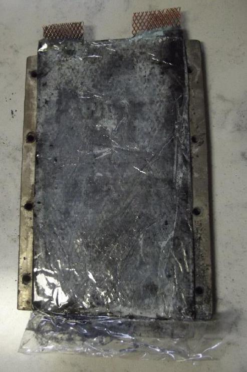 [15th] I put
together a cell with only packing tape, two expanded
copper mesh current collectors, the cobalt mix on one and the dry cell
zinc [oxide] powder on the other, and the two-piece separators in
between. I used 20 grams of the "+" powder, and a little went around
the edge of the separators in a couple of spots. It headed from 170mV
toward 0, so I suspect it's "leaky" because of that. That in spite of
making the separators with 1/4 inch extra on all sides compared to the
current collectors. I need a better cell assembly technique! I put in
about 11 grams of the zinc powder and brushed it around, then wrapped
the tape from underneath around the top. (That's when the powder came
around past the separator.) But I must say that with everything ready
in advance it was pretty quick and easy.
[15th] I put
together a cell with only packing tape, two expanded
copper mesh current collectors, the cobalt mix on one and the dry cell
zinc [oxide] powder on the other, and the two-piece separators in
between. I used 20 grams of the "+" powder, and a little went around
the edge of the separators in a couple of spots. It headed from 170mV
toward 0, so I suspect it's "leaky" because of that. That in spite of
making the separators with 1/4 inch extra on all sides compared to the
current collectors. I need a better cell assembly technique! I put in
about 11 grams of the zinc powder and brushed it around, then wrapped
the tape from underneath around the top. (That's when the powder came
around past the separator.) But I must say that with everything ready
in advance it was pretty quick and easy.
But the cell is so thin and "insubstantial" compared to a
solid plastic housing, with the same active things inside. Eliminating
everything that isn't essential to make a cell is surely where the
energy density is! But I'm sure a group of cells would need something
around the edges to keep them in line.
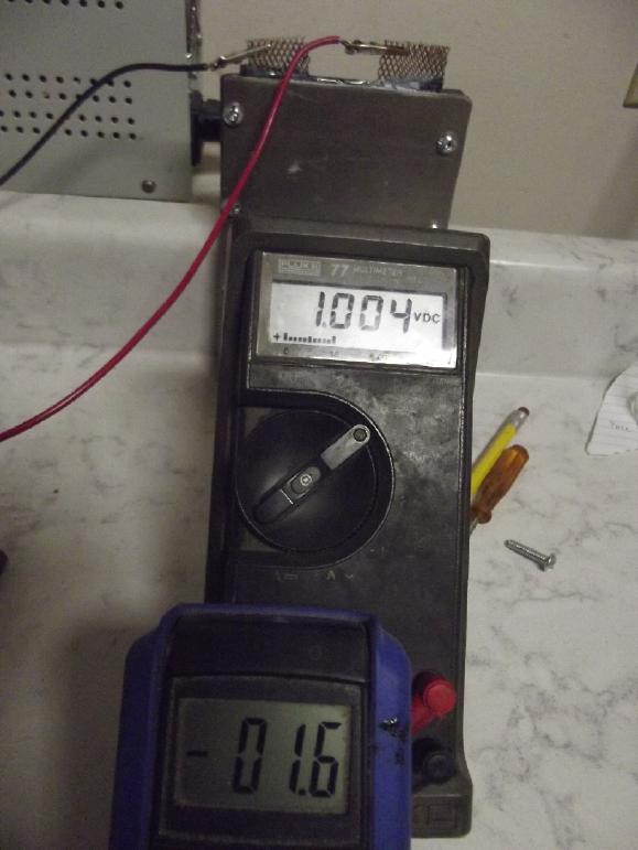 Notwithstanding the seeming leak
I put this skinny,
flexible thing in the clamp plates and the voltage quickly rose up to
the 1.0V of the power supply. And the charging current went down to
12mA (="1.2" on the blue meter), when I'm sure the zinc is pretty much
discharged to oxide and the
voltage wouldn't stay up. Super low current capacity *again*? (The
cobalt was already "charged" to oxide. It would have to bubble oxygen
to allow the zinc to charge? hmm, but the voltage is too low to bubble
oxygen. And if I turn it up, the copper will dissolve! Maybe that's the
problem. How then can the zinc be charged? Well, if it keeps drawing
12mA and if that's really charging the zinc, it should be fully charged
in... 683 hours!?! 28 days!?!)
Notwithstanding the seeming leak
I put this skinny,
flexible thing in the clamp plates and the voltage quickly rose up to
the 1.0V of the power supply. And the charging current went down to
12mA (="1.2" on the blue meter), when I'm sure the zinc is pretty much
discharged to oxide and the
voltage wouldn't stay up. Super low current capacity *again*? (The
cobalt was already "charged" to oxide. It would have to bubble oxygen
to allow the zinc to charge? hmm, but the voltage is too low to bubble
oxygen. And if I turn it up, the copper will dissolve! Maybe that's the
problem. How then can the zinc be charged? Well, if it keeps drawing
12mA and if that's really charging the zinc, it should be fully charged
in... 683 hours!?! 28 days!?!)
I tried adding electrolyte, and tightening and loosening
the clamp screws. These things made only slight differences. The clamp
screws don't seem to need to be done up all that tightly. No doubt
there's some optimum pressure.
[16th] The cell didn't draw much current, but it didn't seem to be
holding the charge. I took it out and cut around the edges where it
might be leaking with scissors and stuck new tape patches around those
edges. I think it was better, but it would be only too easy for more
powder to drift around the edges and connect the two sides. I also
measured it now that it had been compacted: it was only about 2.1 to
2.2 mm thick. I applied charge voltage again and it seemed to be doing
well. The plastic (tape) started to puff up a bit in a few minutes. I
found some much shorter screws and put it back in the clamp. It ended
up just a bit too tall for the clamp plates, the bottom and top ends
marginally sticking out.
A whole new vista of possible sizes opens up since there
was no particular constraining dimension and the clamps didn't have to
be tight enough to worry about bending the 1/4 inch alume. (Tightening
them 'extra' tight doesn't seem to do anything.) It seemed the cells
could be any height, anyway.
[17th] Running a 20Ω load down to .2V
lasts a little longer and a
little longer day by day... 3-1/2, 4-3/4, 6-1/4 minutes. It seems
really hard to charge a cell that will only draw 10-15mA at the low
desired charging voltage or less. It charges back up to where it was
quickly, but adds new capacity painfully slowly. The problem is that
zinc appears to discharge to zinc oxide virtually immediately when
exposed to air. (Never mind after months since I took it out of
alkaline dry cells.) The plus side doesn't. So unless the zinc is put
in as dry zinc powder into a dry cell which is only wetted after
assembly, one is starting with the zinc side discharged. The cobalt
side starts charged. The discrepancy seems to be more than a small
nuisance.
In the first cell with no copper at the plus side I could
charge at a high enough voltage to simply bubble oxygen at the plus
electrode and turn the ZnO into Zn metal at the minus. But in this cell
the copper powder and current collector would dissolve. I seem to be
stuck with that initial 28 days of charging at 1.0 volt unless it
starts to draw more current somewhere along the way.
[19th] The cell continued to suck. Then I thought, that with the
expanded copper grille terminals, it must be letting considerable air
in, and air (O2) seems to discharge the zinc to oxide remarkably
quickly, as I had noted when I had to start charging cells all over
again every time I opened one. I also thought there might be a short. I
slit the tape from the top-center area between the tabs, opening up the
whole top. I stuck in a wedge of varsoled watercolor paper on the "+"
side of the original separator that pushed against the outside tape
edges, hoping to cure any short. Then I squirted in a little more
electrolyte, then covered the entire cell top with another piece of
tape folded over, terminals and all. Then I dug in the aligator clips
to contact the terminals through the tape with minimum little holes for
air to enter.
But by night it was drawing lots of current and the voltage
plummeted if taken off charge. Probably zinc dendrites.
pH
[20th] In the morning it occurred to me to check the pH. Usually,
expecting higher voltages, I had been adding a bit of calcium oxide,
which raises the pH to ~12.7. (It's only slightly soluble, so it
doesn't raise it to 14.) This time I hadn't bothered. It seemed to be
about 5 - mildly acidic. That could certainly screw up most everything,
since the electrode materials could dissolve or at least be much more
soluble! That's probably the real reason for the poor performance -
I've probably wrecked the cell with the acidic pH.
Further reading... Hmm... copper chloride makes a solution
somewhat acidic. Even potassium chloride will be mildly acidic in
higher concentrations. Evidently I was solving these problems that I
was blissfully unaware of by adding the calcium [hydr]oxide to the cell.
Furthermore, looking at the pourbaix diagrams for copper,
it looked like it was pretty much insoluble around pH 8 to 10. If a
cell could be kept within those limits, copper oxide looks to me like
it should be a good "+" electrode material, still with zinc as a
negative. And it's cheap and common! Copper has been used in the past
in early battery development. So, can one control the pH within a cell
to keep it at a specific point like 9 or at least within desired
bounds, without it drifting out over time? And if so how? It looks like
most salts, contrary to the popular term "neutral salts", seem to be
mildly acidic, particularly at higher concentrations. Yikes, "pH
Buffer" -- more to study & learn! Adding some water and some
calcium oxide to the little beaker of electrolyte seemed to bring it up
to pH9 or 10 or so. That's really not alkaline enough for cobalt. At
that point there was Ca(OH)2 sitting on the bottom. Calcium carbonate
looked like it might be about right: pH 9.91 from 1mM to 100mM
(milli-moles). Then I looked up its solubility: 7*10^-4 ! That didn't seem
like it could do much "pH buffering".
Then again I checked the older Co-Zn cell (by adding water
since it had dried out) and found it was around pH 9-11 (my pH papers
aren't very discriminating in that range). That had had Ca(OH)2 and
also some of the somewhat acidic CuCl2, probably both having their
effect. Could that be why the cobalt wouldn't charge back to "Co3O4" or
"Co2O3"?
Maybe I should stick with KCl and Ca(OH)2 for cobalt cells
to keep the pH around 11-12. OTOH, if I was to try copper I should add
the copper chloride and try to have the pH around 9-10. Zinc should be
fine anywhere from 8 to 13 so that's not an issue. (I've read it's
"least soluble" around pH 9.) The whole subject of pH is one that I had
by and large tried to ignore and expected the Ca(OH)2 to maintain the
"pH 12.7" figure I had read somewhere that seemed to work well with
many elements. Past cells with that and KCl salt (no CuCl2) always
seemed to test at around pH 13 to the point where I had stopped
bothering to measure it.
I found some new
Pourbaix diagrams of zinc, too. (Where
have all these come from in recent years? It used to be hard to find
even one or two Pourbaix diagrams of a substance on line, now there are
dozens everywhere! "Images for Zinc Pourbaix". I guess it's in the
image searches. With DuckDuckGo.) Where the Pourbaix diagram for zinc I
had been using seemed to indicate zinc would be fine over a broad range
of pH, from some others it appears it would rather be right around pH
10 than anywhere else.
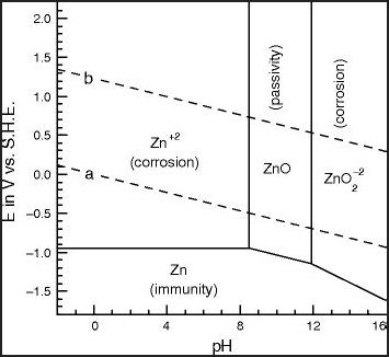
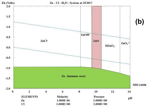 Pourbaix diagrams for zinc
indicate its oxide
is insoluble right around pH 10.
Pourbaix diagrams for zinc
indicate its oxide
is insoluble right around pH 10.
But the diagrams can be misleading... Apparently it's not true.
Elsewhere I've read it is "least soluble around pH 9". (Not insoluble)
[23rd] I had mixed some CaO
(=>Ca(OH)2), CuCl2 and KCl in water in a
very small ointment jar. (With a lid, rather than in a beaker, to keep
out stray Co2.) This "pH 8 to 10" electrolyte I had mixed gradually
attained a pH of about 12. Now I added a few more flakes of CuCl2 to
try to get it down to 11 or 10. Next I checked it was 6! I poured it
into the next size jar up added more water. pH didn't change. Then I
added a gram or so more CaO. It went up a bit. It wasn't as high as I
wanted, but this time I left it, seeing it had seemed to creep up last
time, presumably as more Ca(OH)2 gradually dissolved. Anyway, this sort
of electrolyte mix seemed to have the character of a "pH buffer" - a
strong base plus a weak acid - that would retain a specific pH in a
battery cell. In the evening I checked and it seemed to be around pH
11. If I can put it into a cell and have it not change much, I think I
have something.
I came to realize that pH must be one of the most
neglected and least researched areas of battery making. Once it had
been found (by Jungner, around 1905) that metallic nickel wouldn't
oxidize away in a positive electrode at pH 14 and so could make a metal
current collector instead of using graphite, everybody just went with
highly caustic KOH at pH 14. Nobody ever tried more involved things
like cupro-nickel alloys at lower pH'es.
Copper Oxdies Electrode?
While the Pourbaix diagrams show "CuO" and "Cu2O" for
copper valence +2 and +1, the solubility table on Wikipedia shows
neither but Cu(OH)2 and CuOH instead. I suppose it doesn't matter much.
One Pourbaix diagram shows that copper forms these solid
oxides/hydroxides around pH 8-10 rather than forming soluble ions. At
least in theory, that should mean that copper could be a good electrode
element if the electrolyte is in that pH range. But again there are
differences between diagrams. The second diagram below would suggest
copper works best and is insoluble above pH 11 or so.
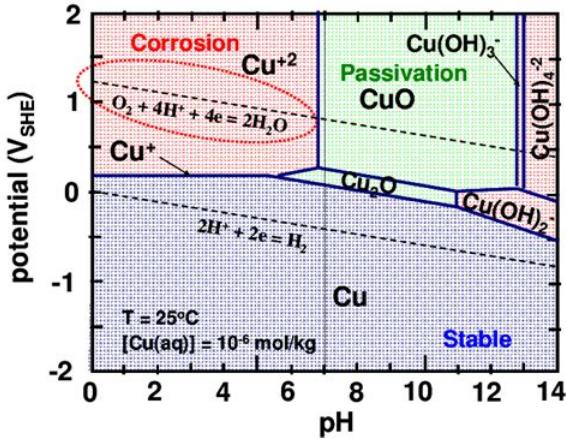
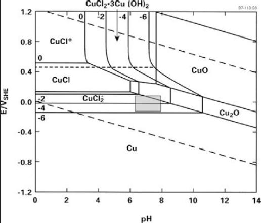 One notes the discrepancies
between various
diagrams made with unknown concentrations
One notes the discrepancies
between various
diagrams made with unknown concentrations
and doubtless for different purposes. Then, to me the term
"passivation" would mean
CuO is an insulator that won't work in a battery. It isn't. Obviously
to the chart
maker it has some other meaning.
At pH 10 the reaction voltages (from the color pourbaix)
are about +.1V for Cu(OH)2 => CuOH and -.1V for CuOH => Cu metal.
Zinc is about -1.0 at that pH, so cell voltage should be around 1.1V
when it is fairly is well charged, dropping to 0.9V in the middle of
the charge well before it really starts to die. (Good warning that your
battery is getting low!) That's assuming both reactions work as
expected and are practical, thus giving the two valence state change
for amazing amp-hours per weight.
I think it's worth trying copper oxides out -- this time
paying careful attention to the pH of the electrolyte.
New Chemistry Batteries: Battery Test/Load Cycler
[17th] If the cobalt-zinc cells had to be charged for weeks and cycled
to get the zinc charged when the cobalt hydroxide started already
charged, I really needed a microcontroller to do it all automaticly. I
finally sat down and started programming with the old laptop and the TI
"Launchpad" with an MSP430-G2553 microcontroller. Boy, it's been a long
time! Anyway, by the end of the day a program just to keep time and
read the voltage was done.
[18th] I connected a battery to the 0 to 1.5 volt analog input via a
pot. to read the voltage. Then I checked and found the input could
instead be 0 to 2.5 volts. The only batteries above that would be
nickel-manganese. Ignoring those for now I could connect the battery
straight to the pin... or straight but through a resistor to prevent
damage. Then I just needed to multiply by some value to get to the
nearest 2 or 3 mV. Let's see, can only do integers... 1500/1024... or,
1500/4=375 so, multiply by 375 and divide by 256 to get reading in
millivolts. Divide by 256 means byte swap - simple. Saves a divide in a
processor with no mult. or div. instructions.
[Hours later] Well, the little number scaling took the rest of the day.
The multiply (that I wrote 3 or 4 years ago) was fine. The "simple"
byte swap for divide by 256 turned into a big headache. It turns out
that when you "mov.b r14,r15", it moves only the low byte from 14
...but zeros the high byte of r15! NOT mentioned in the documentation.
This meant there was in fact no good way to do it in the registers!
(Well, 16 shifts and rotates...) I made a memory location to hold the
byte: "Ug: dw 0". Then I put R15(.w) into that to put in its high byte,
then the desired byte from R14, thus: "mov.b r14,Ug+1". Apparently the
assembler can't add, but it doesn't tell you that. It just puts the
byte into "Ug" instead of "Ug+1". "It's not my fault!" - Han Solo.
These are the sorts of nasty headaches working in an unfamiliar
assembly language that were dead simple to find and fix when I wrote my
own development software. I'd have had it in 5 or 10 minutes. (Well, no
point lamenting my 1990s decade of lost effort developing what is
probably still in some ways a superior operating system.)
Saving the Logged Data
Without having given it much thought earlier, I started
wondering how to get the data log for a battery load cycle out of the
unit and into a regular computer. It seemed such a simple thing at
first. It was something that would have been simple for me in
the 1980s or 1990s. But now computers don't even have a serial port to
simply receive bytes of data, so I can't simply send them. The unit
itself has so little memory I can't even store it internally. There
seemed to me to be just two real possibilities:
1) Write a driver for a serial data (SD) card and save the data as a
file. That would need creating major parts of an entire file system
compatible with (eg) the MSDOS file system so another computer could
read the files created when the SD card was plugged in. (Yes, I know
every digital camera does it.)
2) Write a USB device driver and transfer the data via USB. This too
would not be trivial. Perhaps I could have it tell the computer it was
a keyboard. Then it would be as if the BatteryCycler was typing the
data (mostly elapsed time and the voltage reading) into a text editor,
a spreadsheet or whatever software I chose to have running on the
computer to receive the data. A USB diver would not be a trivial task
either. But it might be the most realistic, and most flexible,
approach. Holy ****! This is some serious "project creep! It suddenly
looks like far more programming, and "off topic" programming, than I
had intended or wanted to get into. No wonder I didn't do this 10 years
ago in spite of the desire!
I went on line and found some "RS232 to USB HID Keyboard"
interfaces. Not just "any" USB to RS232 converters, but ones that mimic
a USB keyboard to input the serial data into program. They Exist! One
at Aliexpress.com for 17$. Whew! I ordered one. I can output the data
as ASCII text to serial just the way I would have done it in past
decades, and this device will translate it through USB into a computer
as if I had typed it. Boy, does that make a tough prospect simple -
Perfect!
[19th] Instead I wrote a blurb to send "RS232" serial out a port pin
with a count delay in a register for baud rate, and a sequence to do a
single load cycle on a cell, stopping at .300 volts. Then I looked at
all the wires dangling from the header strip connectors and knowing
that I still had to put in a couple of transistors and more wires,
decided it needed a piggyback circuit board of some sort. Nothing
complicated. How about a proto board? Did I have one? I dug through the
drawers and found a fairly large one with some pieces already cut off.
Yay! (Where would I buy one around here? I'd have to design & make
my own PCB for this almost trivial job.) I cut off another to make the
"piggyback" board, and wired what I already had to it. (Next, the
transistors.)
I needed a test battery to cycle, and various distractions
came up. It needs the load transistors soldered on and the USB unit to
arrive.
Meanwhile, back at the ranch...
[25th] Millipore Sigma (SigmaAldrich.com) finally decided (after I sent
them much corporate info) that Turquoise Energy Ltd. was worthy of
being their customer, and since the symptoms in the last cell seemed
probably like zinc dendrites, I had decided to wait for the sodium
dodecylbenzenesulfonate ("SDBS") to arrive. Finally it did this day.
Powder form, soapy when wetted. ("Technical grade" - The only one lower
than "reagent grade". Ugh! Well, probably good enough. with thick
watercolor paper.)
I made up a separator sheet that was larger than the
electrodes. I coated it with the new SDBS. And I painted the cobalt "+"
side with calcium [hydr]oxide. With all that I should be able to add an
amount of copper chloride (acidic) to arrive at any pH I choose.
I don't think my plan of taping it all together worked
very well. One piece was too short and electrolyte leaked out the
bottom, and it was black, getting everywhere on both sides of the sheet
and potentially creating 'shorts' or lower resistance paths between
electrodes. Then I had to fold the edges over to fit the cell back in
the clamp. While starting from only 22mV, the cell was soon taking
charge at only 10mA again. Yuk! But checking after a couple of hours
the pH looked like between 11 and 12, which seems pretty much ideal for
cobalt [hydr]oxides. (If the cell didn't have the copper in it, I could
try higher voltages again and see if higher oxidation states work this
time.)
"Plain" Nickel-Zinc Cell
[26th] I got frustrated by
cells with low voltage cells that didn't
seem to work according to my expectations, and decided to do one a
little less unorthodox: "simple" nickel-zinc. Even this had a few of my
"regular" innovations in it, reminding me that I actually have gone
beyond the present state of the art with some of my features. Even a
Ni-Zn cell that should be expected to recharge indefinitely if
everything was made just so and nothing leaked is much better than the
short lived Ni-Zn cells that are currently being made.
I used the small ABS case and clamp set. I used dry cell
zinc powder and extruded copper mesh for the negative. The separators
were (1) a sheet of parchment paper painted with zircon on one side and
osmium doped film on the side facing the zinc. (2) The watercolor paper
was soaked in varsol, dried, and painted thickly with the SDBS
sulfonate powder to stop zinc dendrites. For the positive current
collector I used the cupro-nickel (70%:30%) sheet metal that was
already in it, scrubbed off and painted with a fresh layer of calcium
oxide "cement" (CaO => Ca(OH)2). For the electrode I mixed a batch
of:
01g (02%) Sm2O3 oxygen overvoltage
raising additive
05g (10%) Fine monel power (Ni:Cu ~60%:40%) conductivity raising
additive
44g (balance, 88%) beta nickel hydroxide (Ni(OH)2 - valence II) to be
charged to NiOOH - III.
The 11 grams of this Ni(OH)2 mix that I added, which might
be expected to yield only 90-100 mAH/g and being quite fluffy, seemed
to be a ridiculously fat layer to get just one amp-hour of energy
storage. I only put a few thin grams of zinc powder in the negative but
it much more than matched the nickel side.
I put in some of the "pH buffer" electrolyte already
saturated with Ca(OH)2, plus potassium chloride and the somewhat acidic
copper chloride (CuCl2) to get its pH of around 10 or 11. With Ca(OH)2
already saturating this solution, the layer of it on the current
collector shouldn't change the pH.
After some charging I thought there might be a leak
between electrodes, so I opened it again and put in a couple more bits
of treated watercolor paper where the nickel oxides powder was
spreading out the terminal holes. (Must make the papers cover to the
outside of the terminal holes!) It still didn't seem to be charging
very well, then I remembered that oxygen discharges the zinc and I
plugged the terminal holes with modeling clay. The cell seemed to have
the usual low conductivity of all my cells, but it was charging at 25
or 30 mA from 2.25V. And having only one amp-hour of capacity in the
nickel side, even at 25mA it would "only" take (theoreticly) 40 hours
to charge. (Actually somewhat longer - 10 or 15 hours to get the
Ni(OH)2 up to the "more or less discharged" valence of 2.25 or so - to
25% of it being more conductive NiOOH.)
[27th] It had taken considerable charge overnight and the voltages
dropped off much more slowly than the previous evening. Somehow it was
reassuring that, except for low conductivity, a cell was working as
expected.
If nickel-zinc is somewhat (but only somewhat) low energy
density for electric vehicles, it would be great for stationary
applications, even short-term energy storage for power grids. It
contains no lithium or cobalt, the substances that detractors - those
who offer negatives against progressive solutions but have no solutions
of their own - keep harping on as a reason not to build such things.
(So we keep using ever-depleting fossil fuels instead?)
Now I think about actually making these. They seem to
work. I could start making them while I try and improve chemistries
that should work better. What about construction? Patting in separator
sheets so they don't leak around the edges can't be tedious work. It
has to be simple and straightforward. I start thinking back to some of
my more elaborate 3D printed cells with a lip around the outside where
the separator goes, and a small chamber on top for an electrolyte
reservoir. Maybe I should revive some of those ideas? (Too bad I can't
print ABS with the new printer. Well, PVB maybe? Or would something
simple like HDPE or PP work? Hmm... perhaps I could make a mold and fit
that in with the Plastic Recycling 2.0?)
The flat cell's edges are the key, I think. I could just
print frames that would clamp around the edges of the separator papers.
With slots for the terminals. and maybe with the reservoir edges
surround at the top? The back could just be packaging tape.
- So we would have the bottom/rear frame with tape stuck on behind it,
and a slot for one terminal on the lower/rear/tape side.
- Into this 'box' put in the back current collector with terminal and
the first electrode powder mix. Basicly flatten out the powder so it
doesn't stick up. (Maybe do the zinc side on the bottom because it's
thin and fairly solid.)
- Set the separator papers on top of this lower frame, extending to the
outer edge of the frame.
- Holes and plastic alignment pins in them could hold the upper/front
frame aligned directly over the lower one?
- put in the powder and then current collector for the upper/front
electrode. If it sticks out but can be compacted in like nickel
hydroxide that's okay. Try not to let it get over the edge of the frame.
- Wrap the whole thing with packaging tape and seal all but the top.
Even several layers of tape would be almost weightless.
Well, that's my best idea on that for now. Maybe I'll try doing a pair
of frames in PVB on the 3D printer? Or just with thinner pieces of ABS
sheet? (Some technique has to beat powder pouring itself around the
edge of the tape as you try to wrap it up neatly!)
Note: The reason for wanting a liquid reservoir at the top instead of
just a dry cell is that I just can't tell when a cell has become too
dry to work well. And they eventually do dry out as my Ni-MH "D" cells
have shown. (I took one that wasn't working, drilled a tiny hole, added
water, and it worked again. If the dry cells were refillable, they
wouldn't have become trash in 5 years.) If it's flooded, with however
little excess liquid, one can see if the water is low and add some. Of
course, one should have fewer cells that are big enough to be worth
that bit of biennial(?) maintenance.
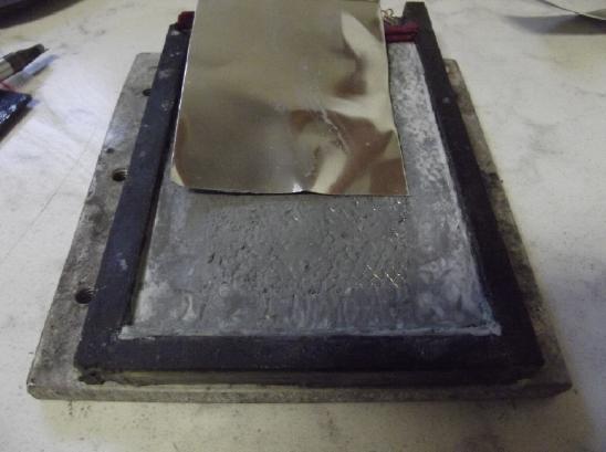 [29th] All this time I've
been attributing the low conductivity of the
cells to the "+" side while using zinc for the "-" on all of them. I
opened the cell and brushed in about 2 grams of zinc nano powder. It
didn't seem to help the short circuit current much, but when I ran a
60Ω load the voltage stayed higher longer, running initially around
1.8V instead of 1.6. I opened the cell again and put in a piece of zinc
sheet metal. It weighed about 5 grams. Now there was something like 8
or 9 amp-hours of zinc to match 1 amp-hour of nickel oxides. (A nickel
oxide electrode to match the zinc is a much thicker and heavier one.
This is the reason to try and find something better than nickel oxides
for the "+" side.)
[29th] All this time I've
been attributing the low conductivity of the
cells to the "+" side while using zinc for the "-" on all of them. I
opened the cell and brushed in about 2 grams of zinc nano powder. It
didn't seem to help the short circuit current much, but when I ran a
60Ω load the voltage stayed higher longer, running initially around
1.8V instead of 1.6. I opened the cell again and put in a piece of zinc
sheet metal. It weighed about 5 grams. Now there was something like 8
or 9 amp-hours of zinc to match 1 amp-hour of nickel oxides. (A nickel
oxide electrode to match the zinc is a much thicker and heavier one.
This is the reason to try and find something better than nickel oxides
for the "+" side.)
Well, zinc
is dirt cheap. Any [reasonable] amount that improves any aspect of
performance is worth adding. The voltage ran a little higher yet. (Not
that a good conductive cell should even notice a 60Ω load!) A
little charging seems to disclose that it's improved somewhat but is by
no means a "Eureka, it's solved!" Is it going to be some
little bit here, some little but there? How many things are there to
improve? not many!
I consider that for the
next zinc electrode I may try
being very simple: sprinkle or brush a little zinc nano powder onto the
parchment separator sheet, put a thin sheet of zinc on that, and set a
copper mesh with terminal tab on top of all, then close the cell. (Or
vise-versa if I put the zinc electrode in first: Cu mesh on the bottom,
Zn sheet, Zn powder.) I may or may not add some of the 'gritty' coarser
zinc [oxide] powder from old dry cells.
[30th] I figured that by this morning it should be pretty much charged
-- at least, the 1 amp-hour nickel side. The zinc with several
amp-hours only needed to match that. A short load test had been
improving the previous day and was again a little better. At least it
was improving instead of deteriorating. But it needed a lot of
improvement before it would drive amps instead of tens of milliamps.
Even the short circuit current was consistently around 1/2 an amp. Why
why why are my cells such high resistance?
[31st] In fiddling around now and then I noted that load performance
had improved when I refilled the cell with a bit more water and
tightened the clamp screws really hard. (Again incremental, not that
order of magnitude that it needs.) I should have done one at a time and
observed which had the greater effect. I added a piece of cardboard and
a bit more plastic to be sure I was tightening on the electrodes and
not just the plastic edges of the case. But I didn't do the screws up
as tightly as I could.
[Feb. 1st] Load performance was slightly better in the morning. Now I
tightened the screws some more to see if it would improve some more.
Fluffy nickel hydroxide, as Edison noted in his nickel-iron cells long
ago, needs to be hugely compacted to get good conductivity. He had
presses tamp a bit at a time into thin cylindrical tubes, interspersed
with fine nickel flakes, and then closed off the tube ends. Can a few
screws on the edge of metal clamps even compact it adequately? But
others have done it differently (eg, in flat perforated metal pockets)
with good results.
The cell
performed reliably for a couple of weeks... no zinc dendrites! But it
had been leaking somewhere around the edge and I had to keep adding
water. I finally took it out of the ABS shell and wrapped it with
packaging tape. Unfortunately that seemed to kill it. No doubt some
powder got around the edge of the separator sheet somewhere. Hence the
above ideas for a new cell construction.
My
Solar
Power
System
The Usual Daily/Monthly/Yearly Log of Solar
Power Generated [and grid power consumed]
(All times are in PST: clock 48 minutes ahead of local sun time, not
PDT which
is an hour and 48 minutes ahead. (DC) battery system power output
readings are reset to zero
daily (often just for LED lights, occasionally used with other loads:
Chevy Sprint electric car, inverters in power outages or other 36V
loads), while the
grid tied readings are cumulative.)
Daily Figures
Notes: House Main
meter (6 digits) accumulates. DC meter now
accumulates until [before] it loses precision (9.999 WH => 0010
KWH), then is
reset. House East and Cabin meters (4
digits) are reset to 0 when they get near 99.99 (which goes to "100.0")
- owing to loss of second decimal precision.
Km = Nissan Leaf electric car drove distance, then car was charged.
New Order of Daily Solar Readings (Beginning May 2022):
Date House, House, House, Cabin => Total KWH Solar [Notable
power
Uses; Grid power meter@time] Sky/weather
Main
DC East Cabin
December
31st 4191.82, 3.99, 79.95, 77.93
=>
2.51 [55Km; 3503@16:30] 6°.
January
01st 4192.15, 4.12, 80.43, 78.27 => 1.91 [3544@16:30] Wind storm.
02nd4193.56, 4.23, 81.07, 78.75 => 2.64 [60Km; 3583@17:00] Calm.
6°
03rd 4193.97, 4.33, 81.26, 78.93 => .88 [3622@17:00] Cloudy,
then stormy again. Trouble with water filter tank.
04th 4194.83, 4.33, 81.61, 79.24 => 1.52 [50Km; 3670@17:30] DC
system
was deprogrammed & disconnected by spray of 0water from filter
tank.
(And car balance charger has been soaked & messed up.)
05th 4195.23, 4.33, 81.69, 79.36 => .60 [3702@17:30] Dark,
clouds, rain
06th 4195.88, 4.33, 81.94, 79.60 => 1.14 [90km; 3743@17:30] Mor ov
same
07th 4197.16, 4.33, 82.62, 80.10 => 2.46 [55Km; 3788@17:00] Dull
sun.
Fixed DC charging in evening.
08th 4198.15, 4.87, 83.44, 80.83 => 3.08 [3823@17:30] A bit more
sun. 1 hr power fail AM. Ran fridge off of DC/inverter
09th 4198.92, 5.07, 83.87, 81.33 => 1.90 [50Km; 3866@16:30] Some sun
in PM. 6°
10th 4199.60, 5.18, 84.20, 81.57 => 1.36 [3898@16:30]
11th 4200.53, 5.26, 85.08, 82.22 => 2.54 [55Km; 3931@17:00]
12th 4201.40, 5.33, 85.59, 82.65 => 1.88 [3968@17:30]
13rd 4201.72, 5.40, 85.69, 82.78 => .62 [90Km; 4011@17:00]
14th 4202.80, 5.51, 86.44, 83.30 => 2.46 [55Km; 4055@17:00]
15th 4203.92, 5.60, 87.18, 83.85 => 2.50 [4091@17:00]
16th 4205.85, 5.69, 88.48, 84.70 => 4.17 [4121@17:30] At last a
little sun and some solar power!
17th 4206.32, 5.76, 88.62, 84.88 => .86 [50Km; 4164@17:00]
18th 4208.08, 5.84, 89.80, 85.88 => 4.02 [4195@17:30]
19th 4209.02, 5.92, 90.40, 86.32 => 2.09 [4229@17:30]
20th 4210.09, 6.00, 91.09, 86.85 => 2.37 [90Km; 4277@17:00] Days
getting a little longer, not sunnier. 8°, some rain.
21st 4213.05, 6.07, 93.58, 88.66 => 7.13 [60Km; 4318@17:30]
Sunshine! Frost AM
22d 4213.55, 6.14, 93.79, 88.86 => .98
[4350@17:30] Rain again
23d 4215.01, 6.31, 94.81, 89.58 => 3.37 [4384@17:30]
24th 4217.65, 6.42, 96.39, 90.68 => 5.43 [4414@17:30] A little nicer
out
25th 4219.85, 6.51, 97.90, 91.64 => 4.76 [55Km; 4451@17:30] Hit
10°!
26th 4220.41, 6.57, 98.09, 91.83 => 1.00 [4482@17:00]
27th 4223.64, 6.65,100.55,93.90 => 7.76 [4511@17:00] Sunshine!
28th 4227.11, 6.73, 2.57, 95.94 => 8.16 [55Km;
4544@17:30] More sun! (but cold: ~0° hi 5°)
29th 4230.58, 6.80, 5.17, 98.03 => 8.23 [4580@17:30]
ditto.
30th 4231.44, 6.89, 5.57, .34 => 1.69
[4630@17:00] Turned heat on in garage to work on truck/mag. torq.
cnvrtr.
31st 4233.39, 7.05, 7.71, 1.79 => 5.78
[4666@17:30]
February
1st 4234.63, 7.19, 8.50, 2.38 => 2.76 [55Km; 4713@17:30]
2d 4236.10, 7.29, 9.46, 3.10 => 3.25 [4751@18:00]
3rd 4236.96, 7.38, 9.85, 3.45 => 1.69 [90Km; 4797@17:30]
4th 4238.16, 7.45, 10.56, 4.04 => 2.57 [50Km; 4840@17:30]
5th 4239.53, 7.56, 11.33, 4.60 => 2.81 [4880@17:30]
6th 4241.88, 7.65, 13.13, 5.89 => 5.53 [60Km; 4919@18:00]
7th 4344.94, 7.75, 15.03, 7.57 => 6.74 [4952@18:00]
8th 4345.74, 7.82, 15.37, 7.87 => 1.51 [60Km; 4995@18:00]
9th 4347.36, 7.93, 16.75, 8.80 => 4.04 [5029@18:00]
10th4349.96,8.06, 18.90,10.11=> 6.19 [90Km; 5071@17:30]
11th4351.09,8.09, 19.49,10.60=> 2.28 [50Km; 5112@18:00]
Chart of daily KWH from solar panels.
(Compare JANUARY 2023
(left) with December 2022 & with January 2022 - but note number of
solar
panels differs from last January.)
Days of
__ KWH
|
January 2023
(18 solars)
|
December 2022
(18 solar panels)
|
January 2022 (15 s.
panels: but just 5 due
to snow until 9th)
|
0.xx
|
5
|
9
|
11
|
1.xx
|
8
|
3
|
8
|
2.xx
|
7
|
5
|
5
|
3.xx
|
2
|
6
|
2
|
4.xx
|
3
|
5
|
4
|
5.xx
|
2
|
3
|
|
6.xx
|
|
|
1
|
7.xx
|
2
|
|
|
8.xx
|
2
|
|
|
9.xx
|
|
|
|
10.xx
|
|
|
|
11.xx
|
|
|
|
12.xx
|
|
|
|
13.xx
|
|
|
|
14.xx
|
|
|
|
15.xx
|
|
|
|
Total KWH
for month
|
93.79
|
79.97
|
57.94
|
Km Driven
on Electricity
|
811.9 Km (Od: 91
(130 KWH?)
|
829.9 Km (Od: 91058)
(135 KWH?)
|
591 Km
(100~ KWH?)
|
Things Noted - January 2023
* More than half the month's solar power came from just the 6 sunnies
days!
Monthly Summaries: Solar Generated KWH [& Power used from
grid KWH]
Month: House system (+ DC system at house) + Cabin system = KWH made
[used from grid]
2019
March 1-31: 116.19 + ------ + 105.93 = 222.12 KWH - solar [786 KWH
used from
grid] (10 solar panels
total)
April - 1-30: 136.87 + ------ + 121.97 = 258.84 KWH [608 KWH]
May - 1-31: 156.23 + ------ + 147.47 = 303.70 KWH [543 KWH] (11th
solar panel connected on lawn on 26th)
June - 1-30: 146.63 + 15.65 + 115.26 = 277.54 KWH [374 KWH] (36V, 250W
Hot Water Heater installed on 7th)
July - 1-31: 134.06 + 19.06 + 120.86 = 273.98 KWH [342 KWH]
August 1-31:127.47 + 11.44+91.82+(8/10)*96.29 = 307.76 KWH [334 KWH]
(12th solar panel connected
on lawn Aug.
1)
Sept.- 1-30: 110.72 + 15.30 + 84.91 = 210.93 KWH [408 KWH]
(solar includes 2/10 of 96.29)
Oct. - 1-31: 55.67 + 13.03 + 51.82 = 120.52 KWH solar
[635 KWH used from grid]
Nov. - 1-30: 36.51 + 6.31 + 26.29 = 69.11
KWH solar [653 KWH used from grid]
Dec. - 1-23: 18.98 + .84* + 11.70 =
31.52
KWH, solar + wind [711 KWH + 414 (while away) = 1125 from grid]
2020
Jan. - 6-31: 17.52 + ------* + 10.61 = 28.13 KWH,
solar+ wind [1111 KWH from grid]
Feb. - 1-29: 56.83 + ------* + 35.17 = 92.00 KWH,
solar + wind [963 KWH from grid]
* The solar DC system was running the kitchen hot water
tank. Now it's only running a couple of
lights - not (usually) worth reporting. So there's just the 2 grid tie
systems:
house and "roof over travel trailer" (AKA "Cabin").
One year of solar!
March - 1-31: 111.31 + 87.05 = 198.37 KWH solar total
[934 KWH from grid]
April - 1-30: 156.09 + 115.12 = 271.21 [784 KWH
from grid]
May - 1-31: 181.97 + 131.21 = 313.18 KWH
Solar [723 KWH from grid]
June - 1-30: 164.04 + 119.81 = 283.82 KWH Solar [455 KWH
from grid]
July - 1-31: 190.13 + 110.05 = 300.18 KWH Solar [340
KWH from grid]
August- 1-31: 121.81 + 83.62 = 205.43 KWH Solar [385KWH
from Grid]
Sept. - 1-30: 110.68 + 65.09 = 175.77 KWH Solar [564
KWH used from grid]
Oct. - 1-31: 67.28 + 42.55 = 109.83
KWH Solar [1360 KWH from grid -- Renters!]
Nov. - 1-30: 35.70 + 20.79 = 56.49
KWH of Solar [1301 KWH from grid]
Dec. - 1-31: 19.78 + 11.31 = 31.09
KWH Solar [1078 KWH used from grid]
2021
Jan: 25.47 +
18.58 = 44.05
KWH Solar [1185 KWH used from grid] (1
solar panel moved to DC system only -- 11 panels)
Feb: 47.18 + 33.22 = 80.40
KWH Solar [1121 KWH used from grid]
Two years of solar!
Mar: 81.73 + 55.22 + 2.2 (DC) = 139.15 KWH
Solar
[1039 KWH grid]
April: 161.83 + 112.35 + .44(DC) = 274.62 KWH
Solar
[680 KWH from grid]
May: 156.25 + 97.22 + 1.29(DC) = 254.76
KWH
Solar [678 KWH from grid]
June: 197.84 + 112.07 + 2.21(DC) = 312.12 KWH Solar
[& 448 KWH from grid]
(Connected
12th solar panel -- 13 panels total but one goes to DC system
only.)
July: 204.35 + 121.21 + 4.06(DC) = 329.62 KWH
Solar [426 KWH from grid; 150(?) KWH used by Nissan Leaf]
Aug: 176.19 + 102.91 + 5.37(DC) = 284.47 KWH Solar [477 KWH
from grid; 165 KWH (est) used by car]
Sept: 94.35 + 51.34 + 3.30(DC) =
152.29 KWH Solar [590 KWH from grid; 155 KWH (est) used by car]
Oct: 77.52 + 41.85 +
4.10(DC) = 123.47 KWH Solar [1066 KWH from grid; 150 KWH (est) used by
car] (2 new panels on pole
making 14 --
but they are mostly in shadows all winter.)
Nov: 34.69 + 18.92 + 3.82 = 57.43
KWH Solar [1474 KWH from grid (ouch!); 140 (est) used by car]
Dec: 24.00 + 5.22 + 3.76 = 32.98 [1589 KWH from grid (ouch
again! Must be the -10°'s); 120 KWH used by car] (New switches allow switching
some panels
between AC and DC as needed, so all 15 are productively employed.)
2022
Jan: 32.83 + 20.54 + 4.57 =
57.94 KWH Solar [2556 from
grid] Double ouch! Trailer 400W heater, Perry's RV 500W heater, bedroom
heat, car using extra power (100 KWH with less driving)... and so
little
sun!
Feb: 66.63 + 32.09 + 3.42(DC) = 102.14 KWH Solar [1118
KWH from grid; 130 (est) used by car]
Three years of solar!
March:128.53 + 82.29 + 3.66(DC) = 214.48 [1124 KWH from grid;
160 KWH (est) used by car]
April: 251.29 + 149.87 + 3.01(DC) = 404.17 KWH Solar
[911
KWH; est. 170 KWH used by car]
May: 255.01(house)+6.46(DC)+140.46(carport)+145.91(cabin)=547.74
KWH Solar [933 KWH from grid;
140 KWH (est) used by car; Bitcoin miner using extra power from 22nd
on.] (3 new solar panels
on carport roof
-- sunniest location around -- total 18)
Jun: 234.54 + 2.10 + 160.70 + 139.18 = 536.52 KWH
[from grid: 864 KWH - dang bitcoin miner!]
July: 232.12 + 4.57 + 143.03 + 139.65 = 519.37
KWH Solar [from power grid: 710 KWH; 165 KWH (est) used by car]
Aug: 205.57 + 4.20 + 157.88 + 137.47 = 505.32 KWH Solar [from
grid: 561 KWH; 145 KWH (est) used by car]
Sept:165.52 + 3.97 + 132.24 + 104.29 = 406.02 KWH Solar [from
grid: 856 KWH; car used (est): 165 KWH]
Oct: 97.96 + 2.86 + 78.76 + 59.04 = 238.62 KWH
Solar [from grid: 1067 KWH; car used (est): 143 KWH]
Nov: 47.37 + 3.30 + 37.81 + 26.43 = 114.91 KWH solar.
[from grid: 1504 KWH; car used (est): 120 KWH]
Dec: 31.05 + 3.11 + 29.46 + 16.35 = 79.97 KWH Solar. [from grid:
1266
KWH; car used (est): 135 KWH]
2023
Jan: 40.57 + 3.06 + 28.31 + 21.85 = 93.79 KWH Solar [from grid:1163
KWH; car used (est): 130 KWH]
Annual Totals
1. March 2019-Feb. 2020: 2196.15 KWH Solar [used 7927 KWH
from grid]
2. March 2020-Feb. 2021: 2069.82 KWH Solar [used 11294 KWH from grid]
(More electric heat - BR, Trailer & Perry's RV)
3. March 2021-Feb. 2022: 2063.05 KWH Solar [used 10977 KWH from grid]
4a. March 2022-August 2022: in (the best) 6 months, about 2725 KWH
solar - more than in any previous entire year!
4.
Money Saved or Earned - @ 12¢ [All BC residential elec.
rate] ; @
50¢ [2018 cost of diesel fuel to BC Hydro] ; @ 1$ per KWH [actual
total
cost to BC Hydro
in 2022 according to an employee]:
1. 263.42$ ; 1097.58$ ; 2196.15$
2. 248.38$ ; 1034.91$ ; 2069.82$
3. 247.57$ ; 1031.53$ ; 2063.05$
It can be seen that the benefit to the society as a whole
on Haida Gwaii from solar power installations is much greater than the
cost savings to the individual user of electricity, thanks to the heavy
subsidization of our power
owing to the BC government policy of having the same power rate across
the entire province regardless of the cost of production. And it can be
insurance: With some
extra equipment and a battery, sufficient solar can deliver essential
power in
electrical outages however long.
https://www.TurquoiseEnergy.com
Haida Gwaii, BC Canada