Turquoise Energy News Report #191
Covering
Research & Development Activities of April 2024
(Posted May 18th 2024)
Lawnhill BC Canada - by Craig Carmichael
[CraigXC at Post dot com]
www.TurquoiseEnergy.com
= www.ElectricCaik.com
= www.ElectricHubcap.com
Month In "Brief"
(Project Summaries etc.)
-
Solar Battery Install - 36 VDC Bedroom Outlet & Heater -
"Everlasting" Cu-Zn (Copper Oxyhydroxide-Zincate) Battery
Development
- Cabin Construction Work - Tinnitus
("ringing in the ears") Relief Project - "Miles the Second" (EV Truck)
-
Cabin Construction
In
Passing
(Miscellaneous topics, editorial comments & opinionated rants)
* Population Explosion/Implosion - Scattered
Thots (DST Gripes etc) - ESD
- Detailed
Project Reports
-
Electric
Transport - Electric Hubcap Motor Systems [No
Reports]
Other "Green"
& Electric Equipment Projects
* Electrical Noise Reduction for Tinnitus Relief: A way to Measure AC
Field Effects!; Beanie
& Pillowcase; EMF Meter; Car Shields; Video Links, Titles
* Cabin Construction
Electricity Storage:
Batteries
* Copper-Zinc cell is fantastic!
Electricity Generation
* My Solar Power System: - The Usual Latest Daily/Monthly
Solar Production log et cetera - Monthly/Annual Summaries,
Estimates, Notes
Solar Battery Install
On the 9th I hooked up a 36 volt LiFePO3 battery comprising 12 cells in
series of ~290 amp-hours, - about 10 KWH - in the garage by the solar
equipment. I had bought a 12S balance charger for same (50A charge,
100A discharge) and now connected it to the "PowMr" solar charge
controller. It wouldn't connect. I checked and rechecked the wiring and
the sense wire to each cell - all correct. Finally I shorted "P-" to
"B-". There was a big spark and it came on and stayed on. Yikes! I
trust it is working and not just internally shorted. As I plan to try
some heavier loads I definitely want it to shut off if the voltage gets
too low. (It seems okay.) The 36 volt Sprint car is still there in the
garage as an alternative battery if it's needed.
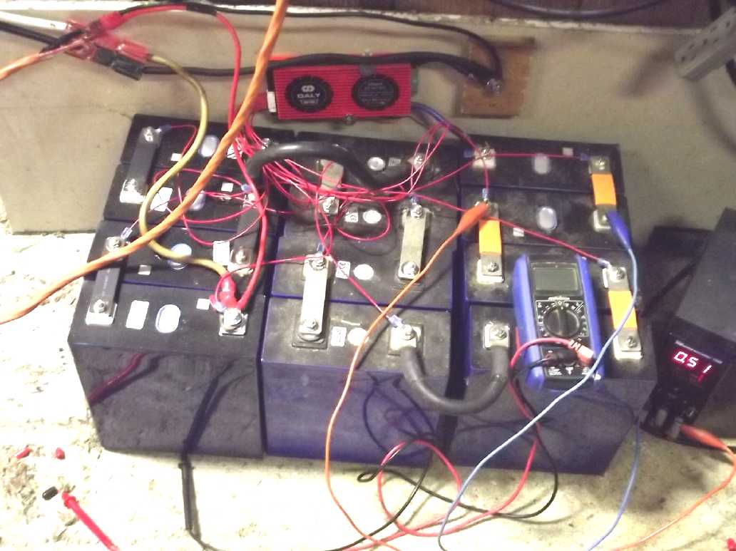 The battery with the balance
charger & a
big ground terminal bolt behind.
The battery with the balance
charger & a
big ground terminal bolt behind.
As the cells started out with uneven charges, I connected a power
supply to supply
additional current individually to the lower ones. In a few days they
were all pretty even.
Next morning (10th) I flipped the breaker back on and
started charging it while I could watch and make sure it was working
right. It did but with the voltage on the PowMr set to 39.3 it didn't
seem inclined to charge much. Of course "36 volts" is the nominal
voltage, but lithium types are usually close to or over 40 volts when
charged. Later I turned it up to 39.6 V and it
started putting out some more juice.
On the 12th I dared go up to 39.9V. The PowMr is peculiar
in that it "automaticly senses" the system voltage and will decide it's
a 48 volt system instead of 36 if the batteries are above 40.0 volts
when it comes on. This is stupidly low since 36V - either lead-acid or
lithium types - can charge to higher than
that. 43 or 44 would be a better minimum. I guess the balance charger
should prevent disaster,
disconnecting the batteries if the voltage gets too high. I'm still
leery, but 39.9 shouldn't be too high. (A slight advantage is
that the PowMr reads a bit low, saying "39.9V" when every other meter
is
saying "40.1" or "40.2".)
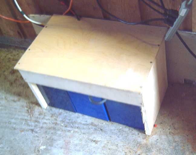 At the end of the month I made a
cover so there
would be no fireworks
At the end of the month I made a
cover so there
would be no fireworks
if something conductive or heavy fell on it or touched the terminals
36 VDC Bedroom Outlet & Heater
An idea in the back of my mind was to run a very small
electric
heater in my bedroom off that battery at night, with the solar
recharging the
battery the next day. That way the large bedroom baseboard heater would
come on less (or even not) and the electric bill would be a bit lower.
It might not work in December when there is so little sun, but in the
spring and fall it should do well.
Of course there are programmable combination units with
inverters and solar charge controllers that connect to the power grid
which will keep your house running on AC power supplied either from the
solar panels, the battery or the grid as desired and available. I
haven't seen any that use the optimal DC battery voltage of 36 volts,
or that intend the user will want to run DC appliances to minimize AC
circuits and the tinnitus that AC fields causes. (This is of course
understandable since so few so far have understood that that (perhaps
including radio and microwave signals) is the cause of their
'everlasting' tinnitus.)
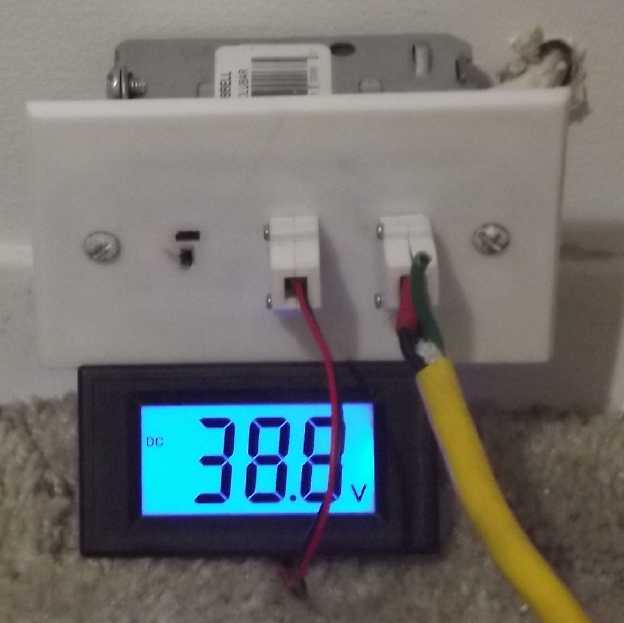 Late afternoon on the 11th I drilled a hole through the
common wall between the bedroom and the garage and put in a 36 VDC
triple wall outlet ...at the baseboard in a corner of the
bedroom and right across from the DC power panel in the garage. It
needed all of 3 or 4 feet
of cable, mostly inside the DC breaker box. I used AWG #14-3 cable.
Counting the bare ground wire that's
actually #14-4, and two #14's tied together is #11, making it #11-2 for
my purpose. I didn't want to cut a big square hole, so I
just mounted the box onto the surface of the wall.
Late afternoon on the 11th I drilled a hole through the
common wall between the bedroom and the garage and put in a 36 VDC
triple wall outlet ...at the baseboard in a corner of the
bedroom and right across from the DC power panel in the garage. It
needed all of 3 or 4 feet
of cable, mostly inside the DC breaker box. I used AWG #14-3 cable.
Counting the bare ground wire that's
actually #14-4, and two #14's tied together is #11, making it #11-2 for
my purpose. I didn't want to cut a big square hole, so I
just mounted the box onto the surface of the wall.
The "self powered" voltmeter with a 36V plug will tell me
if I'm draining the battery too far.
A few years ago I had
bought some high power resistors
thinking about making a small electric heater for 36V. But a few months
ago I
ran across a 750/1500 W radiant heater at a market for 20$, and I had
recently made an adapter cord to plug 120 V appliances into a 36 VDC
outlet
without changing their plug. (User beware!) As this particular heater
had nothing but
the radiant heater elements, a small incandescent "on" light and the
switch, it
could as easily run off the 36 V DC, except it would only be about
75/150 watts with the lower voltage. It's only warm but after a bit I
can feel the heat coming off it, and the bedroom was already warm
when I went for an evening nap. (Or maybe "still warm" from the day,
plus the heater.) After an hour evening nap with the door shut and the
main heater turned off, it was -1° outside and down to 14° in
the bedroom - perhaps instead of 11 or 12°. I also left it on
alone overnight but it got a bit chilly.
 At 36 volts, a 75/150 watt heater
instead of
750/1500 watts. Apparently it was intended to mount on a wall.
At 36 volts, a 75/150 watt heater
instead of
750/1500 watts. Apparently it was intended to mount on a wall.
The "indicator" light on the heater is quite bright at 120V but a good
nightlight at 36V. It can be
switched off separately.
The third plug (must 3D print more shells!) is a lamp by the bed with a
12-60 volts DC regular screw base LED "light bulb".
(I buy lamps at the thrift shop, cut off the plug and solder on a 36V
T-plug. Simple!
Now if only I could find lamp shades around here -- new or used!)
In the morning the battery was recharging at up to 500
watts, 12 amps in sunshine and light clouds. So while I'm using the
heater, the
DC solar readings will go from x10's of watt hours per day (just a few
LED lights) to 1500-2000. (More if I forget to turn the heater off for
the day?) 150W is 3600 WH in 24 hours, so it would drain the battery in
less than three days if I left it on and there was no sun to recharge.
I suppose a couple of kilowatt-hours per day is "chump change" when
you're using 20 or 30. Electric radiant heat is by far the biggest
electricity suck going. Even charging the EV car (usually daily, and
despite every trip being 50+ Km from out here in the country), the
water heater and running the clothes dryer (~weekly) don't take so much
overall because they're not continuous.
But if/when I get the open loop air heat pumping going and
am getting 1500 watts of heat from that same 150 watts of electricity,
then it should really be something! A video predicted that by 2050
millions of people will have left the power grid, preferring solar
panels and batteries. Most of those people wouldn't be this far north
where there's so many winter clouds and short days with very low sun,
but cheap, everlasting batteries and high COP heat pumping are the sort
of technologies to bring it about. And by then there'll probably be
virtually free HE ray energy collection technology available, too - an
even bigger "game changer".
[22nd] Using a power bar, I added a "400W" (40W) heater, which made it
about 195W. On the
24th I
reset the DC "power consumed" meter and in fact used 1950 WH that
night. The "DC solar power made" recharged only 1850 WH, so the battery
was a bit lower on the evening of the 25th. One reason was that one of
the grid ties would "win" and consume all the power leaving nothing for
the DC unit. Turning it off seemed unsatisfactory as the combined
watts, AC + DC were lower, saying that considerable power was being
wasted. I finally settled for reconnecting so that two of the four 250
W collectors went to the AC and two to the DC. The DC also drew from
the
three panels on the wall, but usually seemed to win out and take what
it needed from the grid tie they connected to. (I had put in a three
DPDT switches
arrangement to switch panels between AC and DC, but the batch of
switches I had bought were utter garbage - they burned out promptly in
every power application I installed them in, including the solar power
switching, so I had to remove them. But the grid tie can be switched
off without disconnecting it.
But I'll have to watch that the battery doesn't lose
charge over the days. There's lots of power to recharge it at 8,
10 or 12 amps by early afternoon on sunny days, but keeping the
voltage under 40 (because of the 'PowMr' and also not to stress the
cells by pushing them to their limit, especially in colder weather)
means the charging slows down
earlier than it could and it is still drawing 3-1/2 amps and then
drops below 39.9 volts when the charge stops in the evening.
As noted under my solar power system, lately I've been
checking the BC Hydro meter in the morning as well as evening. When I'm
not driving the EV, Most of the grid power (8 or 9 KWH) is used at
night, presumably mainly for heating my bedroom. During the day, the
solar has been pretty much covering it, the bedroom heat is off, and
only 2-3 KWH more is used. So if 2 KWH is saved at night by the DC
heaters, that's 2 KWH off of 10 or 11 as well as off the whole day.
Sure it's "peanuts" in the overall scheme of things, but it's free
energy at night from the sun, via the battery.
[26th] 200W running for around 10 hours a day didn't seem to tax the
solar/battery system too much, even if the battery charge at the end of
the solar day is 85-90% instead of 100%. In December when heat is most
needed it would run the battery from full to empty in a few days, I'm
sure, but why not take advantage of spring (& fall) sunshine for
free heat? I gathered two more low power heaters (400W, 500W) and
plugged the whole collection of four into a power bar, plugged into the
adapter cord to the 36V DC receptacle. This made a total of 275W
according to the DC system's power meter (~7 amps at 39 volts)
Each heater was a little warm. None of the elements glowed red, but
running on DC they were silent. If it wasn't for the light on the
'1500' watt heater I might forget they were on.
7° out at 9:30 PM - probably the warmest night this
year so far. I didn't turn the 240V baseboard heater on.
[27th] Bedroom temperature dropped a little overnight to 14° - a
little
cool but not bad. And the utility power meter only rose by 5 KWH
instead of the 8 or 9 of recent nights. The little light was reminding
me to turn the heaters off in the morning. This was looking more
practical than I had expected. But then, a fly in the ointment: after a
good string of fine weather, the day broke cloudy, windy and wet, and
such a day wasn't going to recharge the 2400 watt-hours used in the
evening and overnight.
The next day it turned out that it had almost refilled the
battery, and that day it did so. I started charting it. I even left
them on during the day occasionally to take the chill off without
lighting a fire. It didn't seem I would need to worry about the
batteries
not getting recharged until maybe next October or so, but then cloudy
days came along and I had to use less heat at night. I started charting
the DC power generated and used:
DC System running small electric heaters...
Charged, Used (KWH)
29th ~2.650, 2.44
30th 2.647, 2.89
may1 2.749, 2.99
may2 3.059, 2.79
may3 1.749, 2.08
... more next issue.
Early morning May 5th there was a glitch: it turned out one cell (only)
was out of charge and had dropped to 2.3V. (The rest were 3.1_ or
3.2_.) The balance charger shut off the system (and my heat) to protect
it. I had thought they were all pretty well balanced, and anyway 2 or 3
KWH out of 10 should only be a problem if they're very low. I connected
a power supply to charge just that cell extra. If it does it again it
may be well that I bought an extra cell, 25 instead of 24 so I could
replace one if needed. [It seemed fine after that.]
Then finally it was a rainy day, and the battery didn't
fully recharge. I won't try running 150 watts of heat all day and 200+
at night again until it's starting out pretty full.
I finally realize that if I'm not charging the car or
running the clothes dryer, any sunny day I can turn on a smaller
baseboard heater, 500 or 1750 watts, and it will draw from the grid
ties & solar rather than from the power pole. That makes enough
heat in spring and fall to not need to light a fire in the woodstove.
Gosh, imagine that - using my own power instead of sending it to the
power company and then using theirs at night! Of course, it helps that
this spring has been more sunny than usual and warmer during the day.
"Everlasting" Cu-Zn (Copper Oxyhydroxide-Zincate) Battery Development

I always feel like I'm on the brink of having working "new
chemistry" batteries, just an experiment or two away. Then the result
disappoints. But sometimes I learn something, and success surely gets
closer and closer. Now everything sort of works. I think the plan is
finally
right and the only
major
problem remaining is that I'm not using enough osmium in the osmium
doped acetadehyde film mix.
Osmium is a strong catalyst, in this case preventing dissolved zincate
ions from
converting to solid zinc oxide, making a "supersaturated" zincate
solution. (Interestingly, it is said that depending on conditions,
"supersaturated" zincate may convert very, very slowly into oxide -
even taking months. It seems to convert at the separator sheet. Here we
prevent it entirely.) The SDBS in the separator blocks the ions from
migrating out of the electrode space. Thus, the solid zinc dissolves
into liquid state on discharge. On charge, the dissolved ions travel,
touch the current
collector and recharge to zinc metal. In
principle this process
makes for almost 100% utilization of the zinc with no reduction of
capacity in any number of charge-discharge cycles.
 The acetaldehyde-osmium powder
solution looks
dark enough in the test tube,
The acetaldehyde-osmium powder
solution looks
dark enough in the test tube,
but under the microscope in many areas the painted parchment paper seems
to have dark flecks of
osmium only here and there.
I expect that wherever there's no osmium, zinc oxide still builds up.
 Smearing it around helps, but I
still
think it needs
more osmium.
Smearing it around helps, but I
still
think it needs
more osmium.
That zinc side
is paired
up with copper that appears to charge to valence three, presumably
copper oxyhydroxide, a substance not shown in battery literature or in
any Pourbaix diagram. This higher valence allows the copper reactions
to move at least two electrons (if not three) instead of just one, at a
higher voltage and doubling its "amp hours per kilogram" energy
figure. Copper oxide doesn't convert to hydroxide, and it seems only
copper hydroxide will charge to oxyhydroxide. Previous battery
experiments were said to have been with the oxide only, so seemingly no
one has previously seen a copper three valence state in battery
experiments.
I have become confident enough to
draw up the cross section diagram above.
Cabin Construction
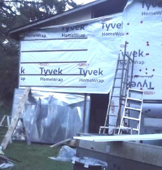
Looking for something easier and faster to install than
gyproc for
the ceiling, I went to Co-op Home Centre and found... coroplast: cheap
and lightweight. Well, why not? I put up three
sheets initially to see what it looked like. The insulation &
rafters behind it don't show through, which was my chief fear, not to
say expectation. Instead,
it looks quite white and better than painted white ceiling because
there are no brush or roller marks. The visible screws with washers to
fasten it, and
sagging a bit at the edges, are drawbacks. I may put batten board
strips along the long edges, and I may dab the screws/washers with
white paint.
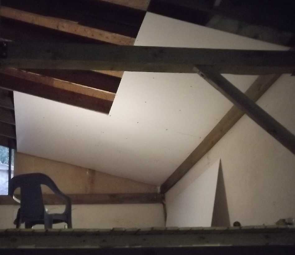 Coroplast ceiling sheets
 I couldn't get
suitable tracks for garage door rollers and I'm still not entirely sure
how I'll get the garage door to roll up or otherwise open and shut.
I couldn't get
suitable tracks for garage door rollers and I'm still not entirely sure
how I'll get the garage door to roll up or otherwise open and shut.
I put up some
plywood strip strapping to screw the metal siding to, then got
distracted and there it still sits a month later.
Tinnitus ("ringing in the ears")
Relief Project
This has been turning into a considerable project and I'm
learning more. especially right at the end of the month, when I found a
reliable way to measure the strength of the electrical field on the
body.
There are EMF and Gauss and RF Field Strength meters, but
I
learned on the 30th that the most reliable way to measure the effects
of power line fields on the body is to use an ordinary voltmeter and
measure AC Body Voltage. One test leed is connected to ground
(an AC
receptacle ground, stuck into damp ground, or whatever -- without
touching it). The other leed is held to connect through your hand. (To
get a solid enough connection I pushed the probe point fairly firmly
into my thumb -- no, not as far as pain or bleeding! Wait... a better
way is to wet your finger and thumb and grip it.) The guy in the
video where I found out about this had a metal drawer handle attached
to the meter leed - surely a good connection if well gripped.
In the video he stated that it was best if the reading was
under .1 V (AC). I think to prevent or cure tinnitus a better figure
would be more like .01 V, AKA 10 mV - or maybe 30 or 50 mV. [Sure
enough, "GreenHome
Institute" gives the following: 0-10mV, no exposure; 10-100mV, mild;
100-1000mV high; over 1000mV (1V), extreme, and a number of adverse
health effects were noted including fatigue or lack of energy,
irritability, stress... Sitting at ungrounded laptop computers was bad.]
I got fairly consistent readings, unlike the vague
wanderings
of the EMF "volts per meter" meters. High field areas gave even several
volts.
By shutting the main house circuit breaker off for the
night on that (and many
subsequent nights), I learned that while in the front yard and in the
closest
end of the house the 14,400 V power line by the highway was indeed a
serious source of electrical noise, the nearby and ubiquitous wiring in
the lavishly wired house was much stronger and in most areas made up
the bulk of it. Except at the highway end rooms (kitchen & dining,
alcove, a washroom), the difference between mains power 'On' and 'Off'
was
night and day. In my bedroom, 'On' readings were in the range of volts,
while 'Off' were
60-120 mV. Inside my new chicken wire "L"
on the bed, 800 mV or 25-30 mV.
The only places down to a 10 mV or less field were inside
the
multipley-grounded metal-clad cabin and out in the woods beyond about
200 feet from the power lines, as well as behind a low rise blocking
the power line's field about 150 feet away. On May 2nd after spending
the night with the house
breaker off, I went out to the cabin and worked on it for a couple of
hours, making it around 10 hours of avoiding electric fields. After
that I could hear that the volume of the ringing seemed substantially
down -
probably
for the first time in years. But mostly, changes in the tinnitus were
only just starting to become audible after 8 hours sleep with the
breaker off.
Grounding the body (or "Earthing" as it has come to be
called) is probably helpful, and some people note great relief from it.
But in my experience so far it has nothing on actually eliminating the
electric field.
 Chicken wire "L" between bed and
outside power
line proved not very effective.
Chicken wire "L" between bed and
outside power
line proved not very effective.
The bulk of the electrical noise seemed to be the 120/240V AC power
wires in
every wall, the floor and the ceiling. To block all that a full Faraday
cage, all
six sides, is needed. The "L" is already pretty inconvenient!
So far, the best thing is to shut the house breaker off at night. (I
despair to try
and find all the individual breakers for all the lines in the bedroom
or passing
through it on the way to the garage and workshop.)
Probably the only real, practical solution for this bedroom would be to
paint the
walls and ceiling with conductive paint and ground them, and to put a
grounded
metal grill under the carpet. (Hmm... tinfoil?)
I don't usually notice anything on the occasions I get
away from
electrical noise sources for a little while - the irritation and
ringing fade so very gradually. Sometimes I notice some change in a
short time, but I wouldn't say it's less ringing. Maybe a lower level
of irritation. Maybe. I only just notice a decrease in sound intensity
after shutting the house breaker off overnight. On May 5th in the early
AM with the house breaker having been Off for six hours, I wouldn't
have sworn that any reduction in the ringing wasn't just my imagination
or wishful thinking. But I had to turn the breaker back On. When I lay
down again, within a minute or so I could feel and hear a strong,
renewed agitation in my ears. Definitely well beyond "just imagination"
- or mere coincidence that it was right after turning on the AC power.
I have just heard a lineman talking of 7200 volt lines on
a youtube video, and
I surmise that that is the usual power line voltage within cities -
half the voltage of the overhead line here. (Does that make this double
the
electric field, or quadruple?) That too may help explain why my
tinnitus is worse
living
here.
Maybe I can finish the upstairs room in the cabin and try
sleeping out
there this summer?
"Miles the Second"
 Friend Tom Sawyer in Victoria has
"acquired an interest" in a Miles ZX40 truck very similar to mine -
just a
somewhat different cargo box on the back.
Friend Tom Sawyer in Victoria has
"acquired an interest" in a Miles ZX40 truck very similar to mine -
just a
somewhat different cargo box on the back.
 They installed long and thin, 300
amp-hour, lithium iron phosphate batteries giving it 21,600 watt-hours
- almost as much as my Nissan Leaf (24,000) and much more than the 8640
WH
in my ZX40. And just as with my stacks of ten lithium ion cells, these
were just
a bit too tall for the allocated golf cart battery space under the
floor, and Tom too had to raise the floor by one 3/4 inch sheet of
plywood thickness.
They installed long and thin, 300
amp-hour, lithium iron phosphate batteries giving it 21,600 watt-hours
- almost as much as my Nissan Leaf (24,000) and much more than the 8640
WH
in my ZX40. And just as with my stacks of ten lithium ion cells, these
were just
a bit too tall for the allocated golf cart battery space under the
floor, and Tom too had to raise the floor by one 3/4 inch sheet of
plywood thickness.
If he can reprogram the motor controller to let the truck
do 50-60 KmPH instead of 40, I'll be Very interested to hear
how it was done, since I am unable to change mine for an unknown
reason. (I hit "Max RPM UP" on the handheld programmer and it goes
up... then after a second returns to the original RPM. With other
parameters the numbers change but the operation doesn't.) But he has
not
done so yet. He says all the roads around Victoria - even the main
roads - have been reduced to 30 or 40 KmPH speed limits!
Gasoline vehicle are at their most efficient running at
60-70 KmPH. Above that wind losses get higher. Below it, the portion of
fuel used just to keep the engine turning over gets higher in
proportion to that used to propel the vehicle. Are the municipal
councils there in league with the oil companies to force people to burn
extra gasoline? Or can all the city councilors in all those local towns
possibly be so ignorant that they think less fuel will be burned
instead of more? I'm so glad I moved away from there!
(Apparently they say "It's safer." Egads!)
Gardening
I have since I moved here intended to expand the "south
wall" (of the house) garden to both sides of the sidewalk. It gets the
most sun and the least wind, so many things grow best - or at all -
there. Last fall I put cardboard down to kill the grass and now I
finally moved part of the deer fence over. Just a few pounded-in posts
- why did it take seven years? I moved the strawberries to the outside
side and planted a shrub and a set of onions there. So far!
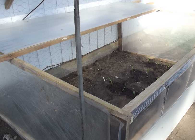 That left the
inside next to the house free for corn. The cool BC west coast by the
ocean isn't conducive to growing corn - it was hard enough to get good
corn in Victoria. The only time I've had any
success growing corn here farther north, I made a "box", a frame with
polyethylene
sheet to keep it warmer until it got too tall in the summer, at which
point I removed the cover. Others too have had spotty success even with
exceptional techniques and south exposures. Now I made a better box,
using tops of Co-op
pizza trays that I have been saving up for quite a while for the top
(in little separate frames) and front, along with other materials.
That left the
inside next to the house free for corn. The cool BC west coast by the
ocean isn't conducive to growing corn - it was hard enough to get good
corn in Victoria. The only time I've had any
success growing corn here farther north, I made a "box", a frame with
polyethylene
sheet to keep it warmer until it got too tall in the summer, at which
point I removed the cover. Others too have had spotty success even with
exceptional techniques and south exposures. Now I made a better box,
using tops of Co-op
pizza trays that I have been saving up for quite a while for the top
(in little separate frames) and front, along with other materials.
I had started the corn in a plastic tray in March (or
early in April?) and the
box project became pressing - by the 20th it was getting too tall, with
too many roots, and had to be planted.
(I didn't plant any toward the back - too shady.)
 The Corn Box
( One more pizza top and I can finish roof section #5 ! )
I bought several interesting looking varieties of
"gourmet" seed potatos. Too many! I planted most of them but didn't get
to planting the regular potatos saved from last year, including my
unique(?) ones with purple skin and white eyes (white flesh). Hopefully
in May I'll find time and a place for them! And hopefully I'll be in
shape to plant more things...
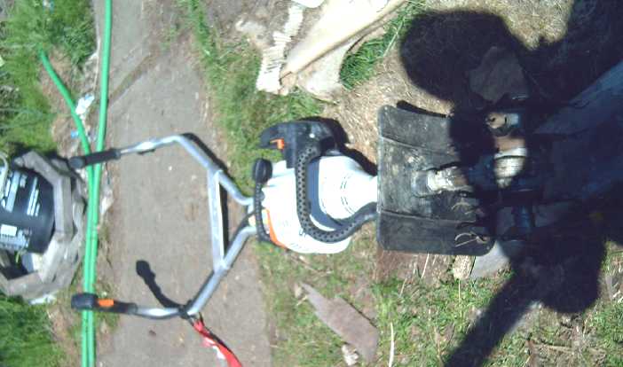 I put a strap
to go around my back on the small no-wheels rototiller that gave me
"tennis
elbow" a year ago so it couldn't yank my arms. A regular strap just
kept falling off and I couldn't use it.
I put a strap
to go around my back on the small no-wheels rototiller that gave me
"tennis
elbow" a year ago so it couldn't yank my arms. A regular strap just
kept falling off and I couldn't use it.
I used it once for a few minutes and somewhat stressed my
arm again anyway, so I let it rest, but then I bought some gyproc. It
was too heavy and in lifting it I
somewhat reinjured my finally healing arm - yet again! I massaged it
where
it hurt and waited a couple more days before doing much more physical
work, but it was still hurting some after I worked. But sometime soon
I'll have to rototill a few more small sections. (One at a time!)
(rats, where did that shadow come from?)
 Redheaded woodpeckers keep drilling holes in the wall at the back of my
shop. I have screwed blocks of wood over many, and one year had to pick
up a lot of bits of strewn fiberglass one had plucked out of the wall.
If I hear them I go around back, wave my arms and shout "Go away
Walter!" (the name in honor of Walter Lantz who created the "Woody
Woodpecker" cartoons after one was repeatedly attacking his roof. When
I was a kid I always liked his little documentaries between cartoons.)
This year after chasing one off a few times I thought to try another
idea and put up a birdhouse over its holes, so they wouldn't feel the
need to make holes. There are a few claw marks under the door, but no
sign that it's been occupied. A friend says they're drilling for grubs,
not for a nest. However, the drilling has stopped. For now.
Redheaded woodpeckers keep drilling holes in the wall at the back of my
shop. I have screwed blocks of wood over many, and one year had to pick
up a lot of bits of strewn fiberglass one had plucked out of the wall.
If I hear them I go around back, wave my arms and shout "Go away
Walter!" (the name in honor of Walter Lantz who created the "Woody
Woodpecker" cartoons after one was repeatedly attacking his roof. When
I was a kid I always liked his little documentaries between cartoons.)
This year after chasing one off a few times I thought to try another
idea and put up a birdhouse over its holes, so they wouldn't feel the
need to make holes. There are a few claw marks under the door, but no
sign that it's been occupied. A friend says they're drilling for grubs,
not for a nest. However, the drilling has stopped. For now.
In
Passing
(Miscellaneous topics, editorial comments & opinionated
rants)
Population
Explosion/Implosion
* First there was the population explosion, and that's still happening
in some places, but videos about a doomsday "population implosion" now
keep suggesting themselves. The more advanced parts of the world, where
good birth control is readily available (not so much womens'
empowerment
and education - which are of course all to the good), have been having
fewer children than the replacement value of 2.1 or 2.2 children per
family, and this decline has been getting steeper and steeper with each
passing decade.
But is there a factor behind the "desire" of so
many to have so few children? I think it's largely the economic plight
and gross uncertainty in which the vast majority find themselves. For
some decades now both the husband and the wife have had to get outside
jobs
- now just to keep a roof over their heads and pay the bills. Mostly
they can't afford to bring a family into the world and don't have time
to properly care for children, and those who can can't be sure their
good situation will last through the upbringing period. So they don't
risk it. Finally they're too old.
And I think population pressure is the key driving factor
behind economic depression and uncertainty. The population grows and
grows despite the unsustainably low birth rates. In Europe and North
America countless economic migrants mainly from overpopulated and still
growing regions, who naturally hope for a better life, anywhere,
are being imported in unprecedented quantities while more and more
citizens in these "desirable" countries are going jobless and homeless.
Adults live in their parents' basements and retired people have to move
in with their children. And so the economic situation gets worse and
worse and the countries' natural citizens have even fewer children, a
"demographic cliff", while anyone who thinks this is bad policy is
labeled a racist. Who has the resources to prosper and grow into their
full potential - and raise a family?
And in recent years it has become a trap for migrants too.
They think they're leaving their homeland for "lands of milk and honey"
where everyone is free and everything is wonderful, only to find
decaying societies full of other imported economic migrants and
impoverished native citizens who are spending their lives working long
hours just to exist. With millions of destitute migrants entering each
year and expecting to be looked after while they learn English and get
established and find a job, and more often finding almost nothing to
help them get there, it's hard to imagine American cities not sinking
into an abyss of crime and violence in the coming years, with Canadian
and European ones not far behind.
Without the importing of hordes of people that keep the
population growing and despite aging populations, the reduction of
population would naturally tend to bring about prosperity: more
resources, more land would be available to each person. In crowded
Japan where the birth rate became low and population has been shrinking
for some time without mass immigration, houses are cheap
because there isn't powerful competition for every living space. People
are not being turfed out of their homes into harsh circumstances. In
the West people mortgage their whole future to buy a house with no good
hope of ever paying it off, or pay staggering rents for any available
space. And still we allow or bring in ever more people. How can we ever
prosper that way?
Scattered
Thots
* Did beaked dinosaurs have gizzards?
* Dinosaurs evolved from frogs, and they looked like kangaroos. Would
they [the original smaller ones] not have hopped like kangaroos?
ESD
(Eccentric Silliness Department)
* So AC, RF and 'microwave' electric fields can cause tinnitus and
apparently a number of other subtle or long term and
not readily traceable health problems. Could "tinfoil hat wearing
conspiracy theorists" know something we don't?
* A result of anger? Put a "d" on the front!
* Spitula: the present tense of Spatula.
* Q: What happened after Napoleon died?
A: (Oh no!) His bones came apart.
* What happened to all the Fords between "Model A" and "Model T"?
* In Norway is there a "Model A Fjord"?
"in depth
reports" for
each project are below. I hope they may be useful to anyone who wants
to get into a similar project, to glean ideas for how something
might be done, as well as things that might have been tried, or just
thought
of and not tried... and even of how not to do something - why
it didn't
work or proved impractical. Sometimes they set out inventive thoughts
almost as they occur - and are the actual organization and elaboration
in writing of those thoughts. They are thus partly a diary and are not
extensively proof-read for literary perfection, consistency,
completeness and elimination of duplications before
publication. I hope they may add to the body of wisdom for other
researchers and developers to help them find more productive paths and
avoid potential pitfalls and dead ends.
Electric
Transport
No
Reports
Other
"Green"
&
Electric
Equipment
Projects
Electrical
Noise
Reduction
(Tinnitus
Relief)
With the knowledge - to me,
the discovery - that it's "forever" energized electric fields that
cause
"forever" ringing of the ears, and that the reason mine has become so
bad since I moved here is that the house is much too close to the
14,400 volt power line as well as the heavily wired house (every wall
and ceiling
has unshielded 120 & 240 V AC power wires, light fixtures and power
outlets and the
floor has wires everywhere) I have started making projects out of ways
to reduce or eliminate the problem. Perhaps these stretch the
definition of "green energy projects". But I've been doing them, with
some but limited success so far.
It occurred to me sometime that virtually wherever I have
lived and slept long term as an adult, there has been (as luck would
have it) an electric receptacle in the wall right by my head, at about
the height of the mattress. These have probably helped keep my ears
ringing all my life. I think when I was a kid there was one beside my
bed but not at the head - but who can remember that far back? (The
house is still there, but Google
street views wouldn't take me inside!)
Apparently in Europe they are starting to take these
things much more seriously than we in North America, and are making
wiring guidelines and passing laws about exposure limits to all sorts
of electric fields, especially for children WRT microwaves (WIFI
routers, cell phones...) but not neglecting other electric fields. The
effects are probably more obvious there, where household voltage is 230
VAC instead of 115. There is no mention of tinnitus among the symptoms,
but some seem to be noting electric fields as the likely root cause.
Apparently "Volts per Meter" electric field gradients can
be measured with an inexpensive EMF meter. There are also magnetic
field measurements usually with the same meter, but I believe it's the
voltage gradients across one's head that cause stresses that result in
tinnitus. From a video about "Electrosmog" such stresses are apparently
sensed by cells themselves even at the DNA level, and I suspect that
when such stresses are felt in the hearing cells that send sound
signals to the brain, tinnitus results.
Unfortunately the first meter I got, model "S8602", says
on the web page it reads 0 to 1000 volts per meter, but it drops out
and reads zero if the reading is less than 20 (and says "Safe". Ha ha,
very funny.) It's good to be able to see there are fields 25 or 100 or
even 200 V/m in my front yard and 25 or 50 or 80 by power
outlets, but I'm sure one very much needs to know if the field is 1 or
10 when dealing with tinnitus, and maybe as low as .1 or 1. I ordered
another meter whose picture showed the reading with a decimal point,
5.1 V/m or whatever it was. [But it turns out this isn't the way to
measure. Body voltage with a regular AC voltameter is the key... read
on.]
I've grounded the metal house roof (four or five separate
sections) at several points. I put 2 inch mesh chicken wire up over the
whole long south wall. But I still need to do the wall facing the power
lines, and probably the other long wall. There's a gaping electrical
hole in the metal roof where the gable end of the main section meets
the lower sloped roof over the kitchen, just right to let electric
fields beam straight into my main living space at an oblique angle.
That should be my next wall target for chicken wire shielding. [Later:
I did it, but measuring "body voltage" (30th, below) it turns out much
of the problem is the wiring inside the house.]
BTW I figure that at such a low frequency a two inch mesh
is fine enough to substantially block it. (I could be wrong.) I'm also
pretty sure that such a low frequency will bend around the ends of any
barrier, so a simple flat plane of barrier won't be very effective
unless it extends a considerable way up, left and right, and touches
the ground or nearly so. Grounding any electric field barrier makes it
much more effective.
And again the cabin I'm building has metal wall and roof,
and I've grounded it at the four corners and the midpoints of the long
walls. I had plans for wiring it all up and had bought everything, but
once I discovered 120V AC power is the cause of tinnitus, the only AC
wiring that got - or will be - put in it is a breaker box in one corner
feeding just one outlet 6 inches from it. This is fed by an extension
cord from the house. The six foot cords from the grid tie inverters for
the solar panels on the roof are the only exposed AC power wiring. (I
could well have dispensed with everything except a single wall
receptacle that plugged into the extension cord.)
Instead I've elected to run the building from 36 VDC. DC
fields are much lower than AC fields, as evidenced by needing far more
turns of far finer fine wire for a DC solenoid compared to an AC one.
And 36 volts is much less than 120 V AC, which has a 171 V waveform
peak to peak. I've said before that I think 36 (nominal) volts is the
ideal building power distribution voltage because it's the highest DC
voltage that virtually never electrocutes anyone but the wires only
need 1/3 of the cross section of 12V wiring and power losses in the
wires are a
much lower percentage.
In addition to powering two grid ties, the solar panels
feed a solar charge controller to a 10 KW (36V, ~290 AH) lithium iron
phosphate battery (12 cells in series). This should be sufficient for
lights and occasional heavier loads except maybe in midwinter at this
high latitude, in which case the battery will have to be recharged from
the AC plug.
I would really like to move in there, but it's nowhere
near ready.
I bought a tuque (AKA beanie) and pillowcase with copper
and silver strands in their fabrics, but an ohm meter generally reads
"open circuit" except at points very close together and I found out
later that while they block radio frequencies well, they're very
poor for 60 Hz fields. Even the alume 'pizza tray' helmet I made
deosn't seem
all that effective unless it's grounded, which can't be done except
when sitting still (eg) at the computer, and even then it's a lot of
bother.
[23rd] The new meter arrived, model VT-ER2. It was quite a
disappointment. The volts per meter readings were wild, and took tens
of seconds to gradually drift up or down and stabilize, if they did at
all. They didn't seem entirely consistent and I'm sure they were wildly
low. The meter would read in some range, and later replaced in exactly
the same spot would read in a different range. In the front yard under
the strong power line field, the S8602 read (say) '100' while the new
meter (gradually) worked its way up to read '14.38' or whatever.
It did seem to vaguely follow field strength if one had
the patience to set it down and then wait for a "stable" reading like
varying between .07 to .13 (doubtless far below the actual value as
well as almost a two to one ratio of readings), and I learned that - in
general - the closer to the ground one was, the lower the field. even
in the cabin with the multipley grounded metal walls and roof.
Evidently one should ideally sleep in a basement with no 120 VAC
lights, plugs or ceiling wiring.
This meter also had RF/microwave detection - its only
redeeming feature. I was
surprised to find it reading about 10 microwatts per square meter
in the kitchen when I turned the "microwave" oven on - 20 right next to
the oven. (Actually they're
centimetric
wavelengths. Who called them "microwaves"?) Is that a little or a lot?
Is it better or worse
than my previous microwave ovens? When the oven shut off, the reading
drifted gradually back to zero over about 20 or 30 seconds instead of
following the sudden change. Sheesh! [Later: apparently cell phones may
be many milliwatts per square meter, 1000 times higher than the
microwave was reading.]
The first meter shut off and read "0" anywhere below 20
V/m. The second one gave utterly unrealistic readings and worse, they
were absurdly unsteady and also inconsistent within themselves. Should
I try for a third
meter? Looking at reviews and selections of meters on AliExpress left
me in the dark about selecting one.
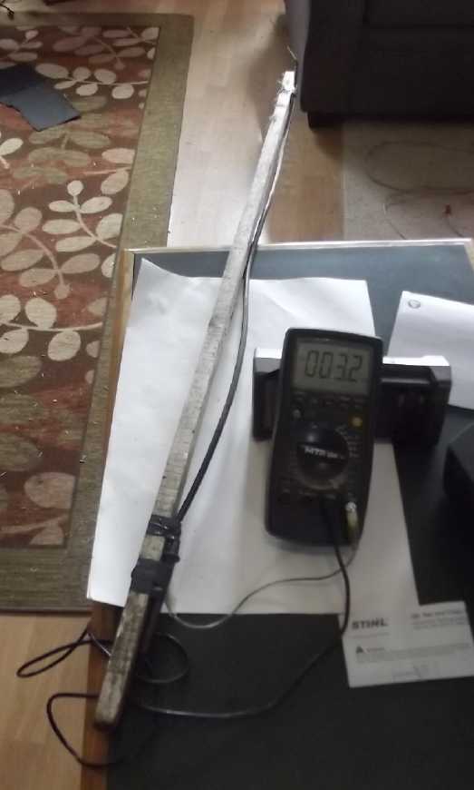 Then I got
another idea: Should I not be able to measure
the voltage difference between two wires placed a meter apart? This
seemed to work quite well - in a relative sense. I put the meter "-" to
the shield of a coax cable which ran along the stick to the far end to
a 3 inch bared section of center wire. The meter's own "-" test lead
was the "-" sensor wire. The center wire at the other end went to meter
"+". The units bore no resemblance to expected "volts per meter" but
consistently dropped and rose depending how close I was to the power
lines, as long as it was held still for the reading. Holding it off the
porch in the air toward the power lines, it gave readings over 200mV
and I had to go to the next range up. As I went from there back into
the forest area away from power, the reading dropped rapidly at first,
then slowly, then stopped reducing at about 2.8-2.9mV AC. I don't know
why, but the only way to read zero was to short the two meter terminals
together. (Humm... The meter itself probably generates that bit of AC
noise. A different meter read 4mV, occasionally 3, instead of
2.8-2.9mV. Only one of my several meters resolves AC to
100µV/.1mV) If I clipped 30 inch alligator clips onto the sense
wire ends, the readings were much higher toward the power lines (like
over a volt or two on the porch), but still dropped to 2.8-2.9mV when
held motionless when (apparently) out of any notable field. But it
would seem that any reading above 3.0 mV or maybe 3.1 is probably
enough to agitate the ears.
Then I got
another idea: Should I not be able to measure
the voltage difference between two wires placed a meter apart? This
seemed to work quite well - in a relative sense. I put the meter "-" to
the shield of a coax cable which ran along the stick to the far end to
a 3 inch bared section of center wire. The meter's own "-" test lead
was the "-" sensor wire. The center wire at the other end went to meter
"+". The units bore no resemblance to expected "volts per meter" but
consistently dropped and rose depending how close I was to the power
lines, as long as it was held still for the reading. Holding it off the
porch in the air toward the power lines, it gave readings over 200mV
and I had to go to the next range up. As I went from there back into
the forest area away from power, the reading dropped rapidly at first,
then slowly, then stopped reducing at about 2.8-2.9mV AC. I don't know
why, but the only way to read zero was to short the two meter terminals
together. (Humm... The meter itself probably generates that bit of AC
noise. A different meter read 4mV, occasionally 3, instead of
2.8-2.9mV. Only one of my several meters resolves AC to
100µV/.1mV) If I clipped 30 inch alligator clips onto the sense
wire ends, the readings were much higher toward the power lines (like
over a volt or two on the porch), but still dropped to 2.8-2.9mV when
held motionless when (apparently) out of any notable field. But it
would seem that any reading above 3.0 mV or maybe 3.1 is probably
enough to agitate the ears.
Mostly inside the metal walled & roofed cabin the
meter read the minimum except near the corner where the one and only AC
receptacle connected the solar grid ties to the grid with their
unshielded "computer" cables. In the house power plugs with wires
coming out of them seemed to be the worst places, and most especially
sitting at my Lenovo computer. At my 2003 antique iMac I type on,
unplugging the 120V lamp and plugging in a DC light gave some reduction
in the reading. (How convenient! I had wired in a 36V DC outlet there
because there was an electrical box hole in the wall anyway, from some
old
satellite TV wiring or something.)
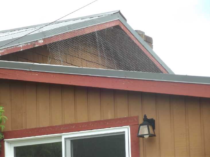 [29th] I finally went up on
the roof and put chicken wire up to plug
the "gaping" electrical field opening at the gable end facing the
14,400 volt power
line, grounding it to the roof by loosening the screws and retightening
with the wire under them at several points. (There's still some small
uncovered triangles, but I probably got the main effect.) I was
probably up there 20 or 30 minutes, and the whole night and next day my
ears were whistling loudly. Later measurements showed very high AC
electric fields, that roof being so close to the 14,400 volt line.
[29th] I finally went up on
the roof and put chicken wire up to plug
the "gaping" electrical field opening at the gable end facing the
14,400 volt power
line, grounding it to the roof by loosening the screws and retightening
with the wire under them at several points. (There's still some small
uncovered triangles, but I probably got the main effect.) I was
probably up there 20 or 30 minutes, and the whole night and next day my
ears were whistling loudly. Later measurements showed very high AC
electric fields, that roof being so close to the 14,400 volt line.
Measuring AC "Body
Voltage!" (The RIGHT way to do it!)
[30th] A youtube suggested video provided new revelations. One can
measure AC "Body Voltage" with a regular voltmeter simply by
holding one probe and grounding the other. Nothing special is required
except to get sufficient connections by grasping the one probe strongly
enough (dampening the fingers helps) and being sure the other is
grounded (but not touching you), to
an electrical ground connection or to the actual ground outside (at
least a little damp). This seems to provide a sure-fire way to measure
how much AC electrical noise is striking one's self.
The video presenter showed 1.7 volts AC where he was. He
said that was too high and said "under .1 volts" was acceptable. I
tried it out and got fairly solid, stable readings wherever I tried it.
There were spots that were surprisingly noisy or quiet in generally
noisy zones, but there were none of those vague, wandering readings
like I got from "volts per meter" meters. By the time I had gone very
far, I decided that ".1 volts" might be okay for general health, but
that it was probably more like .01 volts to prevent or eliminate
tinnitus.
There were three places where I got readings below that
figure: (1) in the forest behind the house more than around 200 feet
from the power line, (2) Behind a small rise 150 feet from it and (3)
inside my cabin with multipley grounded walls and roof - anywhere away
from the one corner with the AC wiring. Inside the house there was no
electricly quiet place. It varied a lot from under .2 to over 4 volts
AC.
At the beach across the highway readings were higher than
I expected. At high tide, just onto the beach 200 feet from the power
lines was still many tens of millivolts if not 100, and the readings
wren't stable. I attributes these to the water and waves. A ways
farther down at the water, it was still 40 or 50 mV. Only at much lower
tides, way out on the beach many hundreds of feet from the power did
the readings drop under 10 mV, eg, to 5 mV at 800 or 900 feet. I had
thought the salt water & wet
sand would absorb the field, but it seems to be the opposite.
On a last note here, where the second leed is grounded
seems to make a lot of difference. I think the AC outlet grounds pick
up a lot of noise from the 120 V AC along the cable. When I was at the
AC wiring corner in the cabin, if I grounded to the AC outlet ground
(at the end of 120 feet of extension cords),
my AC body voltage level appeared to be much higher than if I grounded
to the DC/solar system ground, which went straight to a nearby ground
rod. However, sticking a ground wire from an outside ground rod into my
bedroom didn't make my bedroom any quieter.
"Faraday Cage?" Around Bed
Bed is of
course one effective place to try and reduce
electric fields since one spends much time in one place, sleeping. I
hung a couple of sticks of wood from the ceiling and
hung some chicken wire from those in the shape of an "L" with the long
side between me and the power lines, and the short side along the head
of the bed. The first night I woke up after four hours and noticed
tones of various frequencies popping in and out, each ear separately.
So it seemed to be having some effect. But that was a "one off" and it
certainly did less than I had hoped.
But having the new technique on the 30th I checked my
"body voltage". It was about 2 V and more outside the "L" and still .8
V lying
on the bed. (Target is .01 V?) Small wonder my tinnitus doesn't seem
much better in the
morning! Apparently the cage has to be complete on all sides and
probably top and bottom, has to shield from all that house wiring as
much as or more than from the outside power line beyond the far end of
the house. With that, it became very tempting to shut off the main
breaker for the night, especially now that I have several 36V lights
and some bedroom heat running off the battery.
The other "faraday cage" (besides the metal-lined cabin)
is the mobile chicken yard with
wire on all sides and over top. It's in the front yard nearest the
power line. I tried reading "body voltage" and got readings around .18
VAC inside, where right outside it was around 4.5 VAC. Then I went back
on the roof where I had been working just to see, and got readings from
5.5 VAC at one end to 7.6 at the other. Ouch!
I did shut off the breaker
for the night. (and have done so on many nights since.)
Body voltage was way down: about .03-.05V outside and around .02-.03V
inside the "L" in bed. Again higher than my target .01V and again not
very
effective having only part of a Faraday cage. Still, .02V is a lot
quieter than .8V. What a blessing to be able to measure levels as they
actually
impinge on the body! Yet nobody mentioned the idea except in the one
video. [Another video much later mentioned measuring body voltage, the
same way.]
Waking a few times in the night, for about 6 hours I
wasn't aware of any change. But in the last couple it seemed to me the
noise and tones in my head were changing and getting somewhat quieter,
with louder
pulses coming with each heartbeat instead of always. Could it just be
my imagination, wishful thinking, that it seemed better? When I got up
and turned the breaker back on, within 45 minutes I had my answer as it
got louder and louder and more irritated again. Within two hours it
was
blasting again. As usual. If I didn't know electric fields are the root
of the
problem, I'd probably have just shrugged my shoulders and and hoped it
would quiet down again, without making the connection. It wouldn't.
I don't notice on the occasions I get away from electrical
noise sources for a while - the irritation and ringing fade so very
gradually. Sometimes I notice some change in tone a short time and say
"Hmm, no power lines here", but I wouldn't say it's less ringing. I
only just notice a decrease in intensity after shutting the house
breaker off overnight. On May 5th in the early AM with the house
breaker having been Off for six hours, I wouldn't have sworn that any
reduction in the ringing wasn't just my imagination or wishful
thinking. But I had to turn the breaker back On. When I lay down again,
within a minute or so I could feel and hear a strong, renewed agitation
in my ears. Definitely well beyond "just imagination" - or coincidence
that it was right after turning on the AC power.
Some Video Links
Measuring Your Home for EMFs
https://www.youtube.com/watch?v=GiLvNcUuKMQ&ab_channel=emfanalysis
AC "Body Voltage" WRT ground.
"Down to 100mV if possible" -- [I say 10mV is a better target.]
---
Electrosmog Radiation - Effects on the VDR (and beyond)
https://www.youtube.com/watch?v=T-6dNg0oxkE&ab_channel=DrTrevorMarshall
VDR is Vitamin D reception/receptors
Faraday Cages around beds
---
The Root Cause of Tinnitus - Can we hear electricity?
https://www.bitchute.com/video/FYei2fN7PZvd/
Implicates all kinds of AC electricity: power, RF, UHF.
Huh? -- "The owner has disabled discussion of this video." -- Why? It's
really nice to read other perspectives that may expand on what's in a
video.
---
Another Youtube video suggested the DNA in our cells senses electric
fields.
Something like "Is our DNA an EMF antenna?" Missed putting in the
actual
title & link.
---
This long-winded (1 hr 16 min) presentation on Youtube talks about
mitigagting exposure to power line EMFs without mentioning tinnitus
among many symptoms:
title: "Reducing Exposure to EMFs Part 3 Electrical"
channel: GreenHome Institute
(BTW He's mistaken that 120V AC only goes from +60 to -60 volts. 120 is
the RMS (Root Mean Square "effective") voltage, which is ~170V peak,
+170 to -170, or 340V peak-to-peak.)
Cabin Construction & DC Wiring
I cut and
then put up some 1/2" plywood strapping to attach the metal wall face
to, but then didn't get any farther.
I tried to buy some garage door hardware on line. Rona (and only
Rona) had just what I wanted, but when I entered my postal code, the
page said, "Unfortunately we don't deliver to V0T 1S0". There is no
reason for this. There is no special cost to mail something to here.
But Canada Post can't guarantee its usual delivery times, so it labeled
it a "remote area". This result is becoming more and more of a problem,
when one is usually ordering from a web page and there is no one to
talk to.
I wrote a letter to Canada Post and asked them to please
fix it so it works properly.
No entry there was a problem. Finally I pulled the door
aside and propped some wood against it so it wouldn't blow over in a
wind.
Coroplast Ceiling
I had seen a
video about new plastic wall sections, something like 12 feet wide and
16 inches tall that one installs from the floor up. They attach
together or something. They don't need any filling or painting. One day
at Port Clements I decided to drive the other half of the way to Masset
and see if Co-op Home Center had anything like that. Chances were slim
to none, but I went anyway.
What they did have was coroplast, the 4 by 8 foot sheets
with two layers and square plastic "tubes" between them. 20 $/sheet was
cheaper than gyproc at 30. Way up at the ceiling it seemed pointless to
have "fireproof" gyproc. Assuming LED ceiling lights well installed, a
fire wouldn't start there and if it got there the building must already
be well in flames.
I was a bit leery anyway because they would probably sag,
unequally, and because they were slightly translucent. I thought the
insulation behind would show through. I bought 24 sheets anyway, enough
for the entire ceiling.
A neighbor happened to be there in Masset with a pickup
truck, so I didn't even have to come back another day with the trailer.
It worked out that I traded delivery of the plastic for a heat lamp
bulb that I knew I had, an item which he had been about to buy.
I put up three sheets - half the upstairs room - using 1"
deck screws with #10 washers. Those seemed to be the only thing that
marred the appearance. (and I could probably dab them with white
paint.) The insulation didn't show though at all, and in fact I thought
it looked better than a white painted ceiling because there were no
brush or roller marks in the paint. In fact this was amazingly simple
and saves me countless hours of construction, filling and painting, and
the additional cost of gyproc and the cost of filler, tape, paint,
rollers... The sheets were in fact so light that they were simple to
lift and put up, and they could be held in place temporarily with just
one screw & washer in the middle.
I had thought to put strips of wood between sheets, but I
think it Where the sag is uneven between sheets I could put small
"butterfly clips" to hold the edges together.
On a related note, the thick R28 insulation, 22 inches
wide, wouldn't stay up by itself. For the first sheet I put in a few
long screws to prop up the edges, then put up the sheet. For the second
I put up the sheet first and then slid the insulation in above it. The
third sheet was higher up (needing a short stepladder) and IMHO too
close to the edge of the 2nd floor floor. So I decided to build the
inside wall first so I couldn't take a really big tumble to the ground
if I slipped, misstepped or lost my balance. Also for the rest I'll cut
a piece of plastic to go between the insulation and the rough plywood,
so the insulation will slide down between two slippery plastic surfaces.
Electricity
Storage
Everlasting Copper-Zinc Cells
Everlasting Zincate Electrode: A Theory of Operation
Note
that zincate ions are kept within the electrode by a thick separator
sheet soaked in sodium dodecylbenzenesulfonate ("SDBS" - no dendrites
through
the separator!), and that the electrode contains .5% particles of
zirconium silicate to raise the hydrogen overvoltage, to eliminate
bubbling of hydrogen during charge. A copper current collector and
terminal for the electrode always remains in metallic state because
copper's reaction voltage is lower than zinc's. Further, an osmium film
at the separator prevents buildup of unattached zinc oxide that won't
recharge, which would soon block the electrolyte at separator sheet and
passivate the electrode. With these parameters, the zinc component is
able to dissolve and reform to metal as it wishes, any number of times
ad infinitum.
Zinc attains to three specific states in a relatively
alkaline environment. The first is zinc metal. This is the charged
state. When it discharges to one of the other two forms, the potential
of the reaction is around -1.2 volts - almost the highest that can be
used in aqueous solution without causing hydrogen to start bubbling out
of the water. (Manganese can be made to work at about -1.5V but Mn
& Mn(OH)2
don't have zinc's solubility, which makes essentially all the zinc
atoms available for reaction.)
The two discharged forms are dissolved zincate ion (as K2+
Zn(OH)4-- [or K2+ ZnO2-- according to different diagrams] ...which
forms in a relatively alkaline environment with potassium [as
hydroxide, KOH]) and solid zinc oxide (ZnO). The solubility of zincate
is low. Beyond the limit, usually it converts to solid ZnO and comes
out of solution. Detached ZnO builds up at the surface of the zinc
without recharging until the
pores are blocked and electrolyte can't access the electrode. As the
electrode discharges more and more of the zinc is converted into
zincate and then zinc oxide.
In the 'everlasting' electrode with the film of osmium
catalyst perhaps the excess zincate comes out of solution as
solid K2Zn(OH)4 without converting to ZnO, but
either the ZnO or the K2Zn(OH)4 near the separator is converted back
into dissolved zincate during recharge, as soon as the level of zincate
falls below the solubility limit. The dissolved zincate ions diffuse
through the electrode. They recharge to zinc plating on contact with
the plated zinc (or
copper current collector itself) at charging voltage. (K2Zn(OH)4 + 2 e-
=> 2 KOH + 2 OH- +
Zn; ~ -1.2V) As the zincate ions contact with the metal and recharge to
zinc, the
concentration reduces and more of the solid zinc oxide or potassium
zincate dissolves,
providing more ions to recharge until the electrode is all zinc again
with no zincate or oxide remaining. Unlike chemistries without the
catalyst and the zincate blocking SDBS separator, we are little
concerned about dendrites or the shape or quality of the plating, which
comes and goes with charging and discharging. Nor is the starting form
of the electrode - zinc powder, granules or solid zinc - very important
for the same reason, although a powder starting form allows inclusion
of zircon and graphite powders in the mix.
New New Construction Plan
[1st] I couldn't get a good print of the inner trays with the
traces lifting and making a mess, and finally gave up in frustration.
Why could the old RepRapPro print ABS pretty nicely in open air, but
the iMega can't even in a cardboard box with a 400 watt heater inside
to keep the whole thing warmer?
Suddenly it hit me: The old "Pronterface" slicer did .4mm
thick vertical layers. I was now doing .2mm height with "Cura". Thicker
traces would be stiffer and harder to lift off the bed as more layers
printed on top and shrank as they cooled. Cura calls .2mm "good" and
.3mm "draft mode". But it can be told .4mm, and I will certainly try
it! Also the old printer, with .4mm, printed things a heck of a lot
faster. (I'll have to adjust the designs to account for .4mm layer
heights.)
[2nd] In the paper on zinc-air cell research from 2017, some of
the things I've done were hinted at as possibilities or things being
tried. Sulfonates and calcium oxide were mentioned as well as using "a
heavy metal" at the surface of the zinc. (There's nothing heavier than
osmium!) Owing to these similities of approaches I spent time during 3
days composing a letter, the head author's email being listed in it at
University of Waterloo in Ontario. I summarized my own research and
experiments and on the 2nd added some photos, then sent it.
The leakage current of the present cell grows worse. I
think the parchment paper is too thin to hold enough SDBS to stop all
the dendrites. I'll go back to watercolor paper. I had thought it was
causing low currents and hence wanted to try thinner separators, but
now I expect it was the zinc oxide surface passivation causing most of
the low current problems.
[3rd] I had been noting that the "steady state" current continued
to rise, from the original 7-9 mA it was now up over 40. even after I
took it apart and brushed off the trays. So it would seem then that
conductive paths, zinc dendrites, must be forming across the separator.
No doubt the parchment paper is too thin for the SDBS in it to stop the
zinc ions.
It finally occurred to me overnight that because I hadn't
glued the back on the zinc tray I could open it, scoop out the
contents, put a new treated separator paper on the inside of the grill,
and then reassemble it. I didn't need to make a whole new cell to put
in a thicker watercolor paper complete with SDBS and the new
acetaldehyde. Hopefully that would not only stop the dendrites but make
the whole cell work better. (Maybe I should punch/rip some big holes
through the original separator before I put the new one in?
[4th] I took apart the zinc tray. I scooped out what zinc mix I
could. It was pretty loose and of course a paste rather than
powder. Because the paper was on the outside of the basket weave
'grill' it was smeared between all the "X"es. I had to take a brush and
brush
the rest out under running water.
I got out and trimmed to 50x50mm size a toluened piece of
watercolor paper. When I opened the new acetaldehyde, I realized that I
hadn't smelled that flowery fragrance in years. Doubtless my old stuff
was long since degraded away. I dripped some in a test tube with an
eyedropper and tapped in a bit of osmium powder from the tiny bottle.
(There's more left of my 1 gram of it than I had thought.) I stirred it
with a tiny brush and painted it onto - more like into - the paper. It
took the whole amount, about 1cc. The liquid was clear but with the
powder it painted on a dark color. (If I had tried to make it uniformly
dark I'd have used a lot more, so I didn't. Don't hire me as a
painter.) Then, without waiting for it to dry, I immersed it in SDBS
for an hour.
[5th] The new separator seems to have stopped the dendrites.
Charge current dropped overnight to 2mA. But the cell performs no
better than before. I think I need to rethink what the "surface" of the
electrode is.
In a "standard" dry cell, the zinc is a sheet around the
outside of the cylinder. This gradually dissolves as zinc chloride with
discharge. (until finally it leaks out.) In an alkaline cell, the zinc
is a gritty powder. the large surface area of all this allows higher
currents.
But with a sheet of zinc, the surface of the electrode is
the surface is the surface of the sheet. This is indeed right next to
the separator and so painting the separator with osmium is effective.
With powder the surface of the electrode is the surface of all the tiny
particles that touch the electrolyte. So in theory I should be doping
the whole substance of the powder with the osmium. It seems to me that
would take a prohibitive amount of osmium, the rarest of all naturally
occurring elements.
So what if I go back to using sheets of zinc, or zinc
plated onto copper? Painting the doped acetaldehyde onto a smooth zinc
surface will take less of it than painting it anywhere else and be
right to the point. The SDBS soaked separator will still stop
dendrites. Why didn't I think of trying this a couple of months ago?
[7th] I decided to use one of Peter's zinc coated copper sheets.
I decided to drill a hole in the end of the terminal tab so I could get
a reliable connection with a bolt instead of using an alligator clip
leed. Somewhere on my way to the shop I lost it! I finally gave up
looking and thought I would try coating a piece of copper with zinc
myself. I could melt and did melt zinc with a electric hotplate or my
hot propane torch. But melted zinc apparently desn't like to bond to
copper. I tried borax and canola oil as fluxes. They didn't work. Two
hours later I had nothing but a mess to show for it. A mess - and an
idea.
Electroplating zinc onto copper bonds it, but the zinc
would rather form a spongy face of dendrites than make a smooth
plating. (It looks more like a forest of trees!) But what about
electroplating a thin layer and then dipping it in meted zinc? That
way, the zinc would be adhering to zinc instead of copper. Or,
referring back to a previous plan, I could plate the copper a bit,
squash the zinc flat with the jewellers rolling mill, and repeat to
desired thickness.
I went back in and threw my jacket over the back of the
couch... where I had set Peter's piece when I put it on. I had been
walking back and forth past it as I looked for it. I used it.
I filed off some zinc bumps, painted the zinc face with
osmium doped acetaldehyde, put it in a folded piece of toluene soaked,
SDBS soaked watercolor paper, and put it in the cell case with a
similar size piece of CuNi. Two sheets of metals with a prepared
separator.
I mixed 29cc water with 2.95g KCl, 2.7G Na2SO4 and 1.05g
KOH. Again the sulfate didn't seem to completely dissolve. When I gave
up waiting I poured it in.
It didn't seem to perform too well. I gave up pretty fast
(maybe too fast) and tried putting in a copper box electrode plus, with
the same zinced sheet minus. Charging current went from 4 mA to 24.
Obviously the copper box needed charging. In half an hour it still
didn't run long, but a difference became clear: with a 10 ohm load the
voltage started over 1.05 and 'slowly' dropped to about .95 volts, then
dropped faster and faster until slowing down around 1/2 a volt. This
instead of dropping quickly at first and mostly running way
under 1 volt.
This suggests that the zinc with its smooth surface doped
is putting out good current instead of quickly passivating.
I started checking "How long to drop to .4 volts?" (10Ω) Since it was
mostly above .9V and 80mA, but was charging at a much lower rate,
First.. - 45 seconds
15:20 - 71 seconds
15:30 - 79 s (Chj. before down to 14mA)
16:00 - 102 s; .50V @ 90 s; CB: 12mA; CA: 80+mA on resume chj.
When charge is disconnected the float voltage stays a
while (not measured - less than a minute but not just a few seconds.)
well above 1.3 volts. A 50 ohm load starts well above 1.2 volts and
runs much longer, gradually dropping. A test at 16:08 PM ran for 5
minutes to hit 1.123V.
16:28 - 111 s to .5V; CB 13; CA: 72mA
17:37 - 120 s to .6V; 240 s to .5V; CB: 11; CA 130
It's still running a while over 1 volt, but the
lengthening times are at the lower voltages.
20:40 - 110 s to .6V; 260 s to .5V; CB 8; CA 138
Another 50Ω load test...
22:53 - 12m18s to 1.0V. About 10m dropping to 1.1V and 2m through the
1.0XX range; CB 8; CA 77
It is heartening to see the higher voltages, even the
whole thing doesn't seem to run very long. It will be even more
heartening if it's still working the same or better in a month. It
occurs to me that if a flat sheet of doped zinc doesn't provide full
voltage for very long, I might fold the sheet accordian-wise, starting
with a much wider sheet, to provide more doped surface area in the
50x50mm electrode area. I could also try strengthening the osmium
content of the acetaldehyde.
Short circuit current would start at over 400mA but
dropped rapidly.
[8th] After overnight charge current was down to 4mA. A 10 Ω load test
started at .9XX V instead of over 1 V, and dropped pretty quickly into
the .6XX range. It hit .600 at 2m31s. but then the drop slowed greatly.
At about 5-1/2 minutes I touched the "+" alligator clip to make sure it
was a good connection. That must have moved an electrode. Voltage rose
to about .62 with good current, and didn't drop again to .6V until the
9m28s mark. Any little movement of either electrode, esp. the zinc,
would bring the voltage back over .6 again. I stopped it after about
1/2 an hour, still at about .5V.
The pH was under about 12. Would it work better if it was
higher? I added another .5g of KOH.
At 13:47 I tried a 50 Ω load. It sat right around 1.2V for
at least 10m, then I forgot for a while. In ~35m it had dropped to
1.001V. Then it went more quickly through the .9XX V range. I stopped
it at 40m, ~.91 V. Again it was very heartening that the voltage stayed
so high for so long - much better than with zinc powder. I think
raising the pH (still < 13?) helped.
A very light 100 Ω load delivered over 1.25 V for a fair
while (not timed). 20 Ω started a bit over 1.1 V and ran down to 1.0 in
about 8 minutes.
And the loads would all doubtless run quite a while at .6
or .5 volts; even much longer down to .4 or .3. Next: how to keep the
voltages higher for longer?
[9th] It didn't last. Performance started deteriorating like most
previous cells. Load started at ever lower voltages and lasted shorter
times. Short circuit current dropped to around 200mA by evening. The
one bright spot was that the "idle" charge current (when fully charged)
stayed at 4mA and open circuit voltage dropped only gradually to 1.3
volts.
Next theory: with the PP ironed to parchment paper
separator, performance was poor but stable, except that dendrites
started to form through the thin paper. Apparently the SDBS/parchment
was just too thin. The acetaldehyde with osmium powder was painted onto
(into) the paper and then it was soaked in SDBS.
Then I had tried adding a piece of watercolor paper on the
inside side of the grill. (without removing the parchment on the
outside. Again the acetaldehyde with osmium
was painted on and then the paper was soaked in SDBS. When I painted it
the thick paper soaked up a lot of the solution, using up far too much
osmium to good but doubtless pretty minimal effect.
In the last (zinc plated copper) cell I had painted a film
of doped acetaldehyde
on the face of the zinc. This seemed to work for a day, but then
failed. I surmise that as the zinc turned from metal into oxide and
back, repeatedly, the film was broken up with the electrode surface.
 The zinc plated copper electrode
opened up.
The zinc plated copper electrode
opened up.
It makes sense that the
SDBS blocks the zinc ions, so
acetaldehyde/osmium absorbed into the separator is smothered in SDBS
and useless unless its
at the very inner surface. So I think the thing to try next is to soak
the watercolor
paper in SDBS first, dry it, then paint on the acetaldehyde. I
suspect it won't soak into the soaped paper much, instead making again
a thin film at the surface. Since the film will be on the paper this
time, it
shouldn't be
subject to being broken up with the zinc as it probably was when
painted onto the zinc surface.
Going back to the zinc tray, probably all I need to do is
make a new paper "envelope"
in that manner and put the same zinc inside. Anyway, I'll see how that
works. (I also note that the solid zinc really didn't to behave seem
much different than the powder. I'll try powder again because it's easy
to put a lot of zinc into the electrode that way.
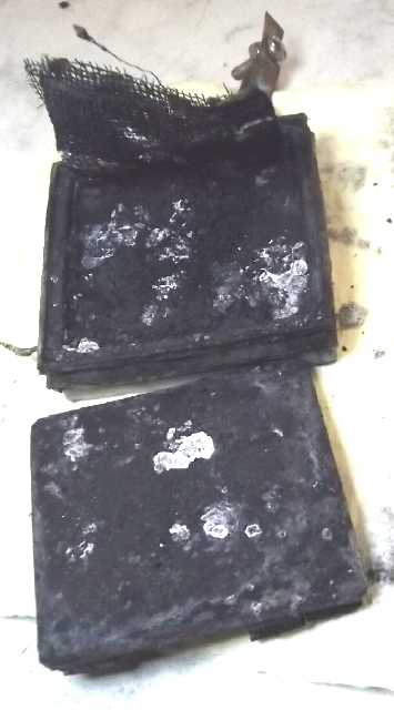 [19th] It's getting hard to
be indoors working on batteries with many
outdoor priorities clamoring for attention in the fine weather,
lengthening days and few precious weeks before the biting flies come
out. Anyway, I finally opened the zinc tray of the two-stack cell. I
had noted that although it didn't seem to work terribly well, it didn't
deteriorate over the days and weeks.
[19th] It's getting hard to
be indoors working on batteries with many
outdoor priorities clamoring for attention in the fine weather,
lengthening days and few precious weeks before the biting flies come
out. Anyway, I finally opened the zinc tray of the two-stack cell. I
had noted that although it didn't seem to work terribly well, it didn't
deteriorate over the days and weeks.
Before when I opened a zinc 'trode, it was usually clumped
light gray zinc oxide. I had assumed it must turn to oxide as it dried
out. In fact, the ever increasing and densifying passivated oxide
during operation was the reason they deteriorated. When I opened this
one it was mostly dark color, probably again zinc oxide but dark owing
to the carbon black. (& of course .5% zircon.) The 3D printed PVB
cover over the zinc tray had curled up, so I cut a new one from ABS
sheet.
 [23rd] I finally got back
to it. (so many things to do!) I cut a piece
of toluened watercolor paper separator to 50x50mm and soaked it in SDBS
for an hour. Then I set it at the woodstove and dried it. Then I mixed
a little more acetaldehyde and osmium and painted it on. It was again
nothing like an even coat as the microscope fotos show.
[23rd] I finally got back
to it. (so many things to do!) I cut a piece
of toluened watercolor paper separator to 50x50mm and soaked it in SDBS
for an hour. Then I set it at the woodstove and dried it. Then I mixed
a little more acetaldehyde and osmium and painted it on. It was again
nothing like an even coat as the microscope fotos show.
I wetted it and smeared it around with my finger, giving a
more even result. And I put it in the zinc electrode tray, osmium side
in of course.
[24th] I crumbled off whatever (ZnO) was
on the current collector
screen as best I could and then repainted it with CaO. Some parts got
more than others. Then I put in 5.5g of the zinc mix (Zn, graphite,
ZrSiO4) and closed the back cover. I put some self-adhesive
weatherstripping foam on the back to push the cover in place, put it in
the cell box and added enough ABS spacer blocks to hold it closed.
For electrolyte I used 30cc water with 3g KCl, 1.5G Na2SO4
and 1g KOH. pH was around 12. This was just about the right amount to
fill the cell.
Voltage started out surprisingly low at .145V when I
turned the meter on but rose in 20 minutes to .65. (Hmm... "in theory"
there's no opening for electrolyte into the 'stack of trays'
electrodes, but of course the cover isn't glued and there are surely
other leaks.) The rise was becoming very slow. I first tried a load of
100Ω. That dropped the voltage to about .60. 50Ω dropped it to .55V.
Then I put it on a 1.5 volt charge. After the usual skirmishes with
poorly connecting alligator clips, it seemed to be charging at around
40mA.
After not too long I tried 10Ω load tests. In the first one it took 60
seconds to drop to .6V. In the second just a few minutes later it took
100 seconds. A few minutes after that it took 2 minutes 37 seconds to
drop to .7 volts. I didn't push it below that. In the next one it
didn't drop below .8V for a whole minute, but then went under .7 in
exactly the same time.
[25th AM] Charge current was still 24mA, but the open circuit voltage
stayed over 1.3V until I started a load test. In that the volage
started at about 1 volt but dropped rapidly through .9 and .8, and hit
.7 in just 33 seconds. [I'm going to use ' and " for minutes and
seconds.] Then it took 8'11" to drop under .6V. The low voltages seem
disappointing, but the next test is usually better. It started
recharging at about 150mA, which dropped under 100 in about 20", and to
30 in something over 3'. [started 9:34. Since it had been discharging
at ~60mA, it should be well charged in maybe 20'.] I took off the lid
to see if there were bubbles and discovered the fluid was below the
tops of the electrodes. I added 7cc of water. It had been ~14' and
charge current (after adding water) was down to 13mA.
I didn't get back for over an hour. Charge current was
8mA. This time it took 1'47" to drop under .8V, 8'6" for .7V and 18'54"
to .6V where I stopped it. It recovered to 1.111V but took 9' to do so.
It was still very gradually rising but here I turned the charge on,
which started a little over 100mA. After some recharge short circuit
current was 400mA. (Will it get to the target 1 amp?)
1PM Charge current 8mA. Checked pH - down to ~11. I added .25g KOH.
13:07 10Ω Load took 17" to drop under .9V; 2'9" .8V; 3'45" .75V; 6'6"
.70V stopped there - other things to do!
13:45 - 8mA chj; Load: 18" .9; 56" .8; 4'56" .7 ...didn't hold
open circuit volts well ...didn't seem very charged!
16:13 - 6mA chj; 1.33V O/C for 1'; .9V 33"; .8V 3'2"; .75V 4'52"; .70V
9'18" - Off - 60" recovery 1.133V O/C
17:47 - 6mA; 1.33 O/C; 35"; 2'45" ended it
22:29 - 5mA; 1.35 VOC; -- .9V; 3'17" .8V; 5'5" .75V; 11'59" .700V
It didn't seem to be working so I added another .25g of
KOH, making 1.5g or (if it's still 30cc of water) 5%.
[26th] That didn't seem to do it either so I added another .5g making
it 6.67% KOH strength. Voltages still seemed low and pH was only maybe
12.5. Charging currents after load tests also seemed surprisingly low.
So in the evening another .25g for 2.25g total and 7.5%.
[27th] A few bubbles. Charge current down to 3mA. Load test again a
little lower than last night. Added another 1/4 gram KOH. Maybe there's
37cc of water now so concentration is less than 7.5%? (Hmm, 7.5% of 7cc
should be .525g)... added another .25g to get to .50 and total 2.75g
KOH.
[28th] If it's not rapidly deteriorating it's not improving either. pH
seemed to still be only around 12.5. I added another .5g KOH. So now
3.25g - if not 10%, then headed there. Why isn't the pH 14 yet? Perhaps
K2Zn(OH)4 zincate has formed and is a lower pH?
[29th] Definitely deteriorating. Just slower than without the osmium
doped acetaldehyde film on the separator sheet. I'm sure that osmium is
the catalyst to continually turn solid zinc oxide into dissolved
zincate up to the limit of zincate's solubility. (BTW osmium is also
the catalyst used in breaking apart N2 molecules from the air in the
production of NO3 (nitrate) for fertilizer and so on.)
But it had been bothering me that the film was at the edge
of the electrode, when zinc oxide could form anywhere between the
current collector and that edge. I started to think the catalyst needed
to be dispersed all through the electrode, perhaps held in some sort of
open matrix like... a screen or layers of screens; an open-cell sponge;
a fuzzy cloth(s)?
Except for the screen, those would absorb a lot of the
rare catalyst. The screen might have too much open space between
surfaces. What about just a piece of open-weave cloth? It's like a very
fine screen. And if all the oxide at its surface dissolves, might it
not be free to move in and out a little within the 'trode, contacting
and dissolving more oxide as the cell charges and more zinc metal
plates onto the current collector? Or if one piece was insufficient,
two or more could be stacked. Rayon came to mind but I had none and no
one on island sells it. How about nylon? That should be inert. Long ago
I bought (among other fabrics) a yellow sample piece labelled "100%
nylon" and I dug it out.
 I cut a square
piece 45x45mm, a size free to drift around
in the 50x50mm electrode, stuffed it into the test tube with osmium in
acetaldehyde, put the stopper back on and shook it to wet the cloth and
absorb some in. Then I fished it out with tweezers and set it on the
plate on the woodstove to dry.
I cut a square
piece 45x45mm, a size free to drift around
in the 50x50mm electrode, stuffed it into the test tube with osmium in
acetaldehyde, put the stopper back on and shook it to wet the cloth and
absorb some in. Then I fished it out with tweezers and set it on the
plate on the woodstove to dry.
I opened the zinc tray, pulled up the current collector
screen, stuck in the cloth and closed everything up. Results were
immediate. Voltage was only .3XX V, and charging current started at
over 200mA. Previously the short circuit current was only 3XX mA. Now,
with less than a minute of charge, a short gave over 500mA. In a few
minutes that was 2/3 of the target 1 amp, and a 10 Ω load started at
over 1.2 volts, although of course these figures quickly decayed with
the low charge. More osmium, better distributed, indeed seemed to be
the answer.
...Or had I once again just shifted some zinc oxide into
contact with the current collector and caused it to recharge, once?
Charging current was soon down to unit milliamps, and quick tests
got worse and worse.
Well, let's see... if ZnO is between the separator and the
osmium, it is likely to block the electrode and not to dissolve.
Perhaps I had made a mistake in not letting the original film on the
separator sheet dry, or in smearing it around "for more uniform
coverage" with my finger, before putting it in? Maybe it would have
worked otherwise? I took it apart again, brushed away the ZnO from most
of the separator sheet, and put the nylon back in. I patted it against
the separator sheet with the brush.
This seemed to make a difference. Charge current still
dropped to lower single digit milliamps, and open circuit voltage
stayed over 1.4 V for a long time, but it started running a 10 Ω load
at higher voltages - even 1.3 volts! I guess it's going to only
gradually convert ZnO to Zn(OH)4-- ion and charge?
I noted in handling
the electrodes that my fingers got the slimy feeling of causticly high
pH and I rinsed them until it was gone and longer. I probably had put
in more KOH than necessary, hoping it would help. Probably 7.5% or less
would be a good figure, with 10% KCl and as much sulfate (Na2SO4 or
K2SO4?) as will dissolve - seemingly somewhat under 10% for Na2SO4.
Unfortunately the good voltages didn't last. I think the
cloth was too far behind the separator paper.
[May 7th] Not having made a successful cell but thinking (once again)
that I finally had the entire formula worked out, even having made a
diagram, I decided to delay this newsletter and give it one more
ambitious try before leaving it until next winter.
My plan was: to treat the watercolor separator with SDBS
and dry it, separately soak a piece of thin parchment paper with the
osmium catalyst dopant and smear it in well, then put a thin piece of
polypropylene non-woven cloth between them and iron them together,
melting the PP into the two papers. (And hoping the heat doesn't
destroy the dopant layer or cause a reaction with the osmium!) ...And
this time I put the painted face of the parchment facing the separator
instead of inward toward the current collector so there's virtually no
space between the osmium and the SDBS.
 Parchment paper painted with
acetaldehyde
containing osmium
powder (later smeared on/in for more
Parchment paper painted with
acetaldehyde
containing osmium
powder (later smeared on/in for more
even coverage)? with watercolor paper? (Hmm... Is this the right foto?)
The dark grains would be the
osmium. I surmise from the
fact that coverage looks thinner than expected and from the poor
performance of the cell that
I'm not putting enough osmium in the mix.
By 2:30 in the night I had
it done in a used 3D printed "box" and in a filled housing with an old
copper electrode. Charging current was so low as to despair of any
immediate results. The zinc was already metal, so it must be the copper
that needed charging. But the charged zinc, with anti-hydrogen bubbling
zircon, didn't want to react.
[May 8th] By the next morning it seemed to be almost zero charging
current and would only put out .555 V into a 10 Ω load. Then it
occurred to me to take out the zinc and put in platinum - or just some
pieces of cupro-nickel sheet - to bubble hydrogen while the nickel
charged. Still using 1.5 volts, I got it up to 30mA with the sheets,
which soon dropped to 15. Oh well, better than nothing! After 5 hours I
put the zinc back in, but only noted that the charging went up a little.
In the evening I did a 10 ohm load test. As usual this was
a bit much current, and the voltage dropped to ~.69 V. Then over five
minutes it rose to .726 V. This was only the second zinc electrode to
do that very conspicuously, the first being the one with only parchment
paper for a separator and the osmium on the zinc face of that. But the
voltage rise wasn't as good as that one, and didn't last as long. With
the
thin osmium'ed parchment paper ironed to the thick toluened, SDBS'ed
watercolor paper with thin PP nonwoven cloth, I think I finally have
all the details right, but I started to suspect it wasn't enough
osmium. The rise in voltage during discharge is surely
due to the conversion of zinc oxide to soluble at the separator sheet.
And if all is well, subsequent discharges will improve rather than
deteriorate. They didn't. They deteriorated. Surely not enough osmium.
[9th] Performance was poor, but some of it seemed to be because of the
positive
side. I had grabbed "any old copper box electrode", since I couldn't
remember which one was which and didn't want to take the trouble to
make a new one. Now the terminal (probably abused previously with
too-high voltages) finished corroding off. I stuck in a couple of CuNi
strips to make contact with the current collector inside. I got a 20
minute discharge with the voltage around .62 volts, which varied wildly
if I pulled or pushed the stuck-in strips. That wasn't much of a test
of the zinc side. I took the other copper box electrode and stuck it in
the old cell box with some CuNi strips and started charging it with
another power supply, to replace the other copper electrode once it had
charged a while. It started charging at 28mA (1.5V), which stayed
steady for a while. Three hours later it was still doing 25mA with the
CuNi sheets bubbling away. Then I touched the wires and it jumped to
46, which soon rose to 56mA - twice as fast! (Dang alligator clip test
leeds!) This seemed much more promising.
I had just finished a disappointing load test with the actual cell,
with voltages in the .6xx range dropping to 5.98V. Without recharging I
traded copper boxes. The voltage was just over 1.3, which was higher
than it had recovered to with the first box. I switched on the 10 Ω
load and the voltage only dropped to .7xx V. So, the culprit in the low
voltages was apparently the copper "+" side, not the zinc at all! ...or
was it just better because I had disturbed things? [I think that was
it.] I ran a short load
test, seven minutes from .747V to .698V. That seemed like better
voltages. Would they stay up there?
Nope. The next test barely was .7 V and I ran it through
the .6XX range for 1/2 an hour. But half way through I thought of
something I haven't done in ages: I stuck in a thin piece of zinc, not
connected to either electrode. This should have the voltage of
a fully charged zinc electrode with no load on it. (Where has my head
been?!?)
At the 15 minute mark, the readings to the two electrodes
were .293V, .944V. The difference is .651 volts. The reading of supply
voltage at that point was .645 - pretty close. So, compared to an
"ideal" discharge voltage of, say, 1.2 volts, the zinc was losing .293
volts and the copper 1.2 - .944 = .256 volts. By the half hour mark,
the figures were .337 and .940, a difference of .603. The actual
discharge voltage was .596 V, again that checks out pretty close. So
the zinc was losing .337 V and the copper . 1.2 - .940 = .260 V. If a
piece of zinc stuck into the electrolyte can be relied on as a
reference electrode, this would seem to indicate that both
electrodes were losing considerable voltage supplying a 10 ohm load. At
a typical figure of 60mA, that's only about 3mA/sq.cm of interface
area. It doesn't say much for either current drive or stored energy
capacity. (Although, the cell would surely have run a couple of hours
if allowed to drop to say .4 volts and even longer at still more
ridiculously low voltages. And being two separate boxes each with its
own separator paper and water in between, it had extra resistance.) I
now thought to measure short circuit current from this pair: just 180mA
(9mA/sq.cm), but it didn't fade at all over several seconds.
If I make the next electrode with more osmium and it all
works as expected - performance doesn't deteriorate and it doesn't get
"leaky" across the separator sheet in the coming days and weeks - then
I believe I will have accomplished what I set out to do in 2008 and
more, creating a fine essentially new infinitely rechargeable battery
chemistry with immense future potential.
Electricity
Generation
My Solar Power System
14 of my 18 mounted solar
collectors are the 305W Hanwha ones I bought as full palettes of 32
each at two different times, and had brought up on the North Arm
Transportation barge. (I sold the majority to
help "off-grid" people "go solar" since they are hard to ship to this
island.) Before I bought those I had mounted my four remaining old
(2011-2013)
collectors at the top of the house roof, ~240 or 260W totaling 1000W,
and tried out a cheap 1000W Chinese grid tie inverter for the first
time. It was exciting to see a quite substantial amount sunlight energy
actually going to the electric power grid.
So now I have 1000W rated from the old collectors and 4270
from the new, 5270 watts. It's said and seems to be true that one
really only gets around 3/4 of the rating in full sunlight, so about
4000 watts. And the grid ties, also in spite of their stated ratings,
don't deliver that full potential to the power lines. On the best days
I might find the three systems (House, carport, cabin areas) delivering
around 1700, 800 and 800 watts (3300W). More commonly it's 1400, 650
and 650 (2700W). All of my solar output tapers off earlier in the
afternoon
than would be expected because of a long line of tall spruce trees to
the west of the house. Ten of the panels are on ~15° south sloped
roofs, which is somewhat too shallow for optimum pickup, especially in
the winter at this northern latitude where those ten get less than 50%
of winter sun.
My "micro" grid tie inverters are the simple "plug-in"
type. One connects the solar panels to the DC side and just plugs the
AC side into an regular power outlet. Instead of drawing power from the
wall, they send the solar power in. These "synchronous inverters" make
waveforms synchronized to the power line they are feeding. They have
"anti-islanding" safety provisions so if the grid power is not present
and within tolerances (or if they're unplugged), they don't put out any
power. I've looked on line and found no mention of any safety concerns
related to these units. (Indeed I have trouble imagining a failure mode
where a grid tie would both not sense power properly and yet still be
functional to actively generate an AC output waveform.)
* Presently (2024/04) the "House Main" system has the four old
collectors (1000W) on a 1400W grid tie, three on the wall (915W) going
to a 1000W tie and two more on the roof (610W) to another 1000W tie.
These are often putting 1400-1700 watts into a wall outlet.
In addition a "PowMr" DC solar charge controller
as of this month feeds a 296 AH, 36 volt battery storing
about 10000 watt-hours of energy. This is connected to the same
collectors as two of the grid ties, electricly in series to make 50-80
volts, since the voltage has to be substantially higher than the
battery voltage in order for the "buck" [voltage reducing] controller
to charge it. It thus runs off seven solar panels.
This battery can be disconnected from both the charger and
the house DC system and connected instead with the 36 V battery (4300
WH) in the Sprint car, either to charge the car or to supply the house
if the new "regular" battery should become drained in a very lengthy
power outage in winter.
* The "House East" or "Carport" system consists of three
panels on the carport roof facing due south at 45° slope (915W),
which get more sun in all seasons than anywhere else on the whole
acreage, and two more angled panels mounted on a pole (610) which are
poorly situated for tree shadows for a good part of the year. These
feed three "700W" grid ties (which have no cooling fans and really put
out half that much). The wall they are mounted on isn't entirely free
of moisture when it's windy. A 1000W tie quit soon after installing it,
and one of the 700W ones doesn't seem to always work properly.
If I was to extend my system anywhere the best place would
be two (or three?) more panels on the carport roof beside the other
three, with a new grid tie, and to enclose the grid ties better.
* The "Cabin" system has four collectors (1220W) on the south
slope of the roof feeding two 1000W grid ties. Like at the house, the
two pairs of panels are combined in series to feed a solar charge
controller that charges a battery identical to the house main
battery. The cabin roof is pretty sunny much of the year but gets a lot
of shade from the long winter shadows of trees to the south - which
really aren't very close.
The Usual Daily/Monthly/Yearly Log of Solar
Power Generated [and grid power consumed]
(All times are in PST: clock 48 minutes ahead of local sun
time, not
PDT which
is an hour and 48 minutes ahead. (DC) battery system power output
readings are reset to zero
daily (often just for LED lights, occasionally used with other loads:
Chevy Sprint electric car, inverters in power outages or other 36V
loads), while the
grid tied readings are cumulative.)
Daily Figures
Notes: House Main
meter (6 digits) accumulates. DC meter now
accumulates until [before] it loses precision (9.999 WH => 0010
KWH), then is
reset. House East and Cabin meters (4
digits) are reset to 0 when they get near 99.99 (which goes to "100.0")
- owing to loss of second decimal precision.
Km = Nissan Leaf electric car drove distance, then car was charged.
New Order of Daily Solar Readings (Beginning May 2022):
Date House, House, House, Cabin => Total KWH Solar [Notable
power
Uses (EV); Grid power meter@time] Sky/weather
Main
DC East
(carport)
After 5 full years (March 2019 to February 2024), I am no
longer recording solar
collection figures daily. (Frequently, and surely monthly.) For the
chart, a figure for "n" days will be divided by "n" and taken evenly as
"n" [more] days of whatever the result is. Oh... now with the DC system
running an electric heater at night (From April 11th 2024), I'm
interested to do daily again for now.
March
31st 1164.64, 2.45, 5.12, 5.88 =>
20.15 [14376@19:00]
April
1st 1168.64, 2.49, 7.23, 8.40 =>
8.67 [14396@19:30] 1 day
3rd 1185.20, 2.57, 15.50, 18.44 => 34.95 [14438@19:30] 2d
(17.48 * 2)
5th 1196.63, 2.68, 22.06, 25.69 => 24.35 [14484@19:30] 2d
(12.18 * 2)
6th 1203.34, 2.76, 25.41, 29.74 => 14.19 [14511@21:30]
7th 1208.12, 2.82, 28.19, 32.65 => 10.54 [14538@20:00]
9th 1223.63, 2.95, 36.47, 41.88 => 33.15 [14598@20:00] 2d
(16.58 * 2)
10th 1228.73, 0.25*,39.47,44.94 => 11.41 [14619@20:00] *Meter was
reset
to zero. DC is now recharging new 36 V, 286 AH battery.
11th 1235.46, 0.40, 43.24, 49.24 => 14.95 [14640@19:30] DC
system as of late
PM is making up battery charge while running 150W electric heater at
night.
12th 1241.55, 2.01, 47.48, 54.34 => 16.24 [14648@20:00] 1st
day running heater (~13 hrs)
13th 1244.67, 3.44, 50.61, 57.96 => 11.30 [14671@21:00]
14th 1250.64, 4.99, 55.28, 63.04 => 17.27 [14690@20:00]
15th 1254.60, 6.42, 59.42, 67.49 => 13.97 [14716@20:30]
16th 1261.09, 8.05, 64.73, 74.23 => 19.97 [14723@20:00]
17th 1268.11, 9.17, 70.44, 81.09 => 20.70 [14739@20:00]
18th 1277.08, 1.55, 75.63, 87.67 => 22.29 [14753@19:30] Beautiful
sunshine (and the biting flies haven't arrived yet)!
19th 1287.06, 2.93, 80.80, 94.16 => 23.02 [14772@19:00]
20th 1291.99, 4.01, 84.14, 4.03 => 13.38 [14802@25:00]
Shouldn't hav mentioned the sunshine!
21st 1296.76, 5.82, 88.27, 8.97 => 15.65 [14809@20:30]
22d 1300.55, 7.68, 91.86, 13.71 => 13.98 [14832@24:00]
23rd 1304.96, 9.13, 95.34, 16.44 => 12.07 [14851@20:30]
24th 1309.93, 1.67, 4.78, 21.52 => 16.50 [14862@20:00]
-- Got 2nd heater ("400W"), running two in BR at night on 36BDC; total
a bit under 200W. Cloudy day. Will DC recharge make up for usage?
25th 1317.72, 3.52, 10.88, 28.86 => 23.08 [14872@20:00] Sunshine
again!
26th 1326.30, 5.43, 16.53, 35.67 => 22.95 [14882@20:00]
27th 1328.42, 6.87, 18.80, 38.00 => 8.16 [55Km; 14899@19:30;
50Km]
28th 1331.83, 8.97, 22.32, 41.90 => 12.93 [14922@20:30] Actual rain
- it was needed! Then sun again. (Later, hail 9-12mm balls)
29th 1339.18, 2.44, 27.71, 47.93 => 21.21 [38Km; 14934@20:00]
30th 1346.53, 5.33, 33.28, 54.46 => 22.23 [52Km; 14951@20:30]
May
1st 1353.35, 8.32, 38.95, 60.53 => 21.55 [14959@20:30] Bedroom heat
from batteries only.
Seems the battery charging IS keeping up with usage... either when
it's
sunny or if I don't run too much heat, too long!
Chart of daily KWH from solar panels.
(Compare April 2024
(left) with March 2024 & with April 2023.)
Days of
__ KWH
|
April
2024
(18 Collectors)
|
March 2024
(18 C's)
|
April 2023
(18 C's)
|
0.xx
|
|
|
|
1.xx
|
|
|
|
2.xx
|
|
1
|
|
3.xx
|
|
1
|
|
4.xx
|
|
1
|
|
5.xx
|
|
2
|
2
|
6.xx
|
|
8
|
3
|
7.xx
|
|
|
1
|
8.xx
|
2
|
4
|
1
|
9.xx
|
|
1
|
1
|
10.xx
|
1
|
|
1
|
11.xx
|
2
|
|
1
|
12.xx
|
4
|
2
|
2
|
13.xx
|
3
|
|
2
|
14.xx
|
2
|
|
1
|
15.xx
|
1
|
3
|
4
|
16.xx
|
4
|
|
|
17.xx
|
3
|
|
1
|
18.xx
|
|
1
|
1
|
19.xx
|
1
|
2
|
1
|
20.xx
|
1
|
1
|
|
21.xx
|
1
|
|
2
|
22.xx
|
3
|
|
1
|
23.xx
|
2
|
|
1
|
Total KWH
for month
|
483.68
(Very Sunny!)
|
337.81 |
408.83
|
Km Driven
on Electricity
|
1066.8
(~~140KWH)
|
1049.1
(~~140 KWH)
|
1038.7 Km
(160 KWH?)
|
Things Noted - April 2024
* Quite sunny & warm: much of April felt like summer!
* Because of the DC bedroom heaters, I've been checking the BC Hydro
meter in the morning as well as evening. When I'm not driving the EV,
Most of the grid power (8 or 9 KWH) is used at night, presumably mainly
for heating my bedroom. During the day, the solar has been pretty much
covering it, the bedroom heat is off, and only 2-3 KWH more is used. So
if 2 KWH is saved at night by the DC heaters, that's 2 KWH off of 10 or
11 as well as off the whole day. Sure it's "peanuts" in the overall
scheme of things, but it's free energy at night from the battery.
* On sunny days the PowMr charge controller brings the battery up to
39.9V before noon or so, and the charge current starts to drop. But the
more the battery has been used, the higher the current still is by the
end of the day. Eg, for 1.5 KWH heater use, it might drop to 3 amps,
where for 2.5 KWH it might still be doing 7 amps until it can't. The
evening battery voltage is lower once charge is off, eg, 39.8V for the
lesser use and 39.5V with the greater.
Monthly Summaries: Solar Generated KWH [& Power used
from
grid KWH]
As these tables are getting long, I'm not repeating the log of monthly
reports. The reports for the first FIVE full years (March 2019 to
February 2024) may be found in TE
News
#189,
February
2023.
2024
Jan KWH: 31.37 + 3.14 + 16.85 + 16.82
= 68.18 [grid: 909; car (very rough estimates): 160]
Feb KWH: 96.52 + 2.36 + 49.67 + 52.98 = 201.53
[grid: 791; car: 130]
FIVE full Years of solar!
Mar KWH 150.09+ 1.63 + 93.59 + 92.50 = 337.81 [grid: 717; car:
140]
Apr KWH 181.89+35.55 +123.50+142.74 = 483.68 [grid: 575; car: 140]
Annual Totals
1. March 2019-Feb. 2020: 2196.15 KWH Solar [used 7927 KWH
from grid; EV use: -] 10, 11, 12 solar panels
2. March 2020-Feb. 2021: 2069.82 KWH Solar [used 11294 KWH from grid;
EV use: -
(More electric heat - BR, Trailer & Perry's RV)] 12 solar panels
3. March 2021-Feb. 2022: 2063.05 KWH Solar [used 10977 KWH from grid;
EV use ~~1485 KWH] 12 solar panels, 14 near end of year.
4a. March 2022-August 2022: in (the best) 6 months, about 2725 KWH
solar - more than in any previous entire year!
4. March2022-Feb. 2023: 3793.37 KWH Solar [used 12038 KWH from grid; EV
use: ~1583 KWH] 14, 15, 18 solar panels
5. March 2023-Feb. 2024: 3891.35 KWH Solar [used 7914 KWH from power
grid; EV use: ~1515 KWH] 18 solar panels
Money Saved or Earned - @ 12¢ [All BC residential elec.
rate] ; @
50¢ [2018 cost of diesel fuel to BC Hydro] ; @ 1$ per KWH [actual
total
cost to BC Hydro
in 2022 according to an employee]:
1. 263.42$ ; 1097.58$ ; 2196.15$
2. 248.38$ ; 1034.91$ ; 2069.82$
3. 247.57$ ; 1031.53$ ; 2063.05$
4. 455.20$ ; 1896.69$ ; 3793.37$
It can be seen that the benefit to the society as a whole
on Haida Gwaii from solar power installations is much greater than the
cost savings to the individual user of electricity, thanks to the heavy
subsidization of our power
owing to the BC government policy of having the same power rate across
the entire province regardless of the cost of production. And it can be
insurance: With some
extra equipment and a battery, sufficient solar can deliver essential
power in
electrical outages however long. (Feb 28th 2023: And it's probably well
over 1$/KWH by now the way inflation of diesel fuel and other costs is
running.)