Turquoise Energy News #213
Covering
Research & Development Activities & Projects of
February 2026
(Posted March 5th 2026)
Lawnhill BC Canada - by Craig Carmichael
[Subscribe: email to
CraigXC at Post dot com ; request subscription]
Main URL TurquoiseEnergy.com Also at craigcarmichael.substack.com
Baffle Boxes for the heat exchanger
finned pipe
radiators have taken countless hours to 3D print.
Styrene foam insulation will surround this whole
assembly including the middle space.
Month
In "Brief" (Project Summaries etc.)
* New Chemie Battery Tests, Builds - Building New Indoor-Outdoor
Heat Exchanger for OLAHP
In Passing
(Miscellaneous topics, editorial comments & opinionated rants)
* Scattered Thots - Electrosmog Department - ESD
- Detailed
Project Reports -
Electric Transport - Electric Hubcap Motor
Systems - no report (will I ever find time to
finish the next motor?)
Other "Green" &
Electric Equipment Projects
* Open Loop Air Heat Pumping - New Indoor-Outdoor Air Heat
Exchanger
* Faraday Cabin Construction (Ceiling Beam)
* Kitchen Hot Water Systems
* A Very Little Gardening
New Battery R & D
* New Organic/Monel-Zinc Cell - More Battery Cell Revisions
* A Recap: The Everlasting Zinc Electrode - Better Zinc
Compartment?
Electricity
Generation
* Additional Solar Rebate - 75%
* New Fotos of my Solar Panels
* SEVEN Years of Solar Electricity
* The usual Latest Daily/Monthly Solar Production log et
cetera - Monthly/Annual Summaries, Estimates, Notes
February in Brief
BC Hydro Solar Installation Rebate
BC Hydro wrote me again after I had my 5000 $ rebate
cheque, asking for all my receipts with "Paid" written on them.
The reason? I am after all, being on a diesel powered "micro
grid", eligible for the credit I was told was available at the
renewable energy symposium: 75% of costs, maximum 20,000 $. It
wasn't on the rebate application or hinted at anywhere except when
I was told about it verbally.
It makes sense for BC Hydro to offer that much
because it costs them (IIRC) about 62¢/KWH for diesel fuel while,
in order to have a uniform price throughout the province, they
charge us 12¢. So we are heavily subsidized and it's BC Hydro that
saves most of the money when rooftop solar is installed. I guess
they didn't want the vast majority of ineligible people all over
the province inquiring about it or trying to claim it - or
complain that it was "unfair". But I wonder how many eligible
people looked and saw only the 5000 $ maximum and decided not to
start a solar project. I myself had started telling people the
reputed 75% must be only for native band community projects, which
was another category.
Kitchen Hot Water
I improved on the "on demand hot water" unit I had
installed in the kitchen under the sink. Definitely not as good as
the 15 liter hot water tank under the sink was! I wrote of this
below, here.
Gardening
I covered part of the main garden with black plastic
to kill weed seeds, fertilized my fruit trees, and put my beehive
up high on a roof, hoping bees would adopt it. Here.
Battery R & D
I spent most of my time on batteries again. I think I made some
good progress. I just couldn't seem to get performance out of the
organic/monel/copper electrodes, so I finally went back to nickel
manganates or nickel manganese oxides (typical: NiMn2O4
discharging to NiMn2O3OH, NiMn2O2(OH)2, etc). For now.
Silver
 I made a new cell for this, first
stretching a bar of silver to over a foot long to make silver
current collectors from, by repeatedly annealing it and running it
through the jewelers rolling mill. Silver is the best conductor
and doesn't oxidize in lower voltage "+" electrodes. (It also
doesn't oxidize when it's heated to red hot, unlike copper.)
I made a new cell for this, first
stretching a bar of silver to over a foot long to make silver
current collectors from, by repeatedly annealing it and running it
through the jewelers rolling mill. Silver is the best conductor
and doesn't oxidize in lower voltage "+" electrodes. (It also
doesn't oxidize when it's heated to red hot, unlike copper.)
I also ordered the other ingredients for
electroplating silver using sodium thiosulfate (that I should have
ordered along with the thiosulfate). Then I can try silver plating
graphite foil to improve its surface conductivity, as using silver
current collectors, even paper thin, would be far too expensive to
be practical for production. Graphite has the advantage over metal
in that holes or cracks in the plating won't corrode it and so are
of little consequence. It seems that nickel-iron cells where the
steel is nickel plated usually corrode. It only take one initial
gap in the plating to get it started.
But I'm thinking of a short, thin silver wire for the
terminal because my graphite gasket or graphite foil terminals
keep breaking off.
Nickel Manganese Oxides
Experimenting again with these, I found they work
quite well - just at lower cell voltages than I had previously
expected. My preconceived idea that they should have the voltage
of a nickel hydroxide electrode, and so the charged cell should be
1.8 volts, had for an absurdly long time kept me from recognizing
that they work fine when charged to 1.5 volts instead of 2.0. The
discharge voltage starts under 1.3 .
Again the means I used to form this compound is to
dissolve nickel oxide, potassium permanganate and graphite powders
in acetone and stir occasionally. As the acetone evaporates, they
crystallize into combined "epitaxial" spinel structure crystal
forms. (In production one would recapture the evaporating acetone
and reuse it.)
When a Ni-MH cell discharges, the voltage drops from
about 1.35 volts to 1.15 volts and then "falls off a cliff" as it
were. There's virtually no energy left at that point. As the
NiMn-Zn cell discharges it drops slowest from around 1.3 volts to
1.2 volts but then proceeds on down to .9 volts and even lower at
varying rates, still putting out current. It may move up to four
electrons per molecule, the later ones occurring at lower
voltages. That's good amp-hours and a very long warning that the
battery is low. The best nickel (hydroxide) electrodes move 1.5
electrons or fewer. Until recently it was less than ~.8 electrons.
Then means were found to charge the nickel substance to higher
valence. Still it needs a lot of nickel substance to match a
little zinc.
Zinc Electrodes
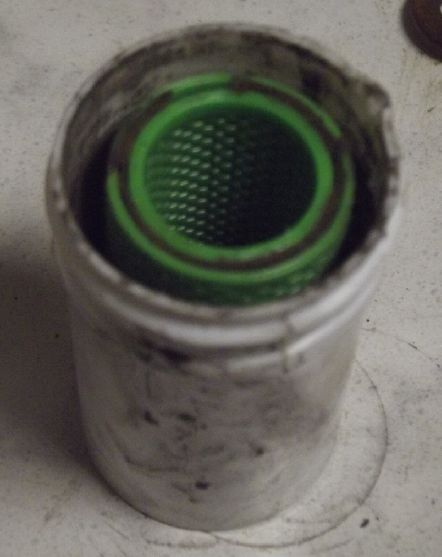
NiMn2O4 cell with double perforated
basket to
protect the (black) separator paper, and (at first)
a rolled sheet zinc for a center "-"
electrode.
 I was initially trying
out both Cu and NiMn electrodes using the copper wire with a zinc
sheet wrapped around it as the negative electrode. With this I
didn't get much out of the NiMn 'trode either.
I was initially trying
out both Cu and NiMn electrodes using the copper wire with a zinc
sheet wrapped around it as the negative electrode. With this I
didn't get much out of the NiMn 'trode either.
In some frustration I broke open an alkaline Mn-Zn
"D" cell and scooped out some of its zinc powder mix. Lo and
behold, it started working! I changed all that for zinc powder
with zircon additive so it could recharge without bubbling
hydrogen. I still don't understand why sheet zinc doesn't work.
Doesn't zinc discharge to dissolved zincate ions, leaving more
exposed zinc on the sheet? In the standard dry cell sheet zinc
works fine. Apparently not in alkali. Zinc electrochemistry seems
more and more complicated!
I stirred the dry cell zinc or tamped it down during
the discharge test, and that would bring the voltage up. Yet it
never came back up to the original and gradually got lower. One
more thing I wish I had done: as the voltages got lower, I should
have added some more zinc mix from the dry cell. If the voltages
kept dropping, that would mean it was the NiMn that was weakening
first. If they had risen up again, it would mean it was the zinc
side. This would be very good to know, since my cells all seem to
supply (much) fewer amp-hours than I expect them to. I'll have to
try this experiment again. I had thought the zinc couldn't be the
problem side, but now I see it just might be.
Copper Again
Having found it was the zinc side that was causing
poor results with the copper organic/monel/copper 'trode, I also
realized that by the last iteration after adding so much more
monel, the mix was very short of material to assist with
conductivity - maybe only 1% silver. 5 wt% silver oxide or 20 wt%
graphite powder or conductive carbon black would be much better.
By this time I was testing the new manganates-zinc cell, so I just
remembered for later.
Filler & Dry Cells
I had all along realized that a dry cell would be
ideal, but how could one make it a dry cell when the zinc in the
basket was on the bottom and the electrolyte had to flow through
the separator all the way to the top? The basket had to be filled
with electrolyte. Then I got the idea to put in an inert filler
material in the inner basket. Something that would contact the
separator paper from top to bottom even tho the zinc itself didn't
even come close to filling the basket.
First I tried cotton batten - cotton swabs. I split
them open and put the zinc powder on top, then the copper wire,
then closed them up again and stuffed it all in the cell.
I zinced up the cotton swabs.
Folded them up and stuffed them in.
To my surprise it didn't work worth a darn. It
probably didn't poke through the perforations to touch the paper,
but I put in enough electrolyte to fill inside and bridge the
gaps. The zinc powder was probably just too loose - mostly
not connecting to the wire.
 Then I thought of sand. I filled the
zinc basket with fine casting sand (13 grams), then drilled a hole
in the middle with a 5/16" brass tube, and poured 11 grams of the
zinc powder mix into the hole. Then tamped it down and stuck in
the copper wire. I covered it with a little more sand. This Did
work. And at this point, although the entire cell was full of
electrolyte water, none was liquid on top that could be poured off
or splashed - essentially a "dry cell". Although it's pH 13
instead of 14, it's safer for users if highly alkaline electrolyte
isn't "spillable".
Then I thought of sand. I filled the
zinc basket with fine casting sand (13 grams), then drilled a hole
in the middle with a 5/16" brass tube, and poured 11 grams of the
zinc powder mix into the hole. Then tamped it down and stuck in
the copper wire. I covered it with a little more sand. This Did
work. And at this point, although the entire cell was full of
electrolyte water, none was liquid on top that could be poured off
or splashed - essentially a "dry cell". Although it's pH 13
instead of 14, it's safer for users if highly alkaline electrolyte
isn't "spillable".
 Then I thought of early battery
experimenters using open porous clay pots as electrode separators.
Since I was trying to fill the zinc basket anyway, suddenly the
idea didn't seem so silly. After looking at "how to make
firebricks" and buying a huge bag of perlite, instead I tried just
sand and clay. To make sure it was porous, I used just 10% red
clay and 90% fine sand. When I fired it in the mini kiln it seemed
good. I could suck or blow air through it. just right, I think. A
few grains of sand would come off the outside when I rubbed it.
I'm sure it'll work.
Then I thought of early battery
experimenters using open porous clay pots as electrode separators.
Since I was trying to fill the zinc basket anyway, suddenly the
idea didn't seem so silly. After looking at "how to make
firebricks" and buying a huge bag of perlite, instead I tried just
sand and clay. To make sure it was porous, I used just 10% red
clay and 90% fine sand. When I fired it in the mini kiln it seemed
good. I could suck or blow air through it. just right, I think. A
few grains of sand would come off the outside when I rubbed it.
I'm sure it'll work.
More pottery experiments followed.
Toward Production
I shaped the sample ceramic by hand as a shape with
rounded corners. I have the thought that one can have the solid
pot instead of the 3D printed plastic inner basket. The
bottom must be glazed to be non-porous, and the separator paper
wrapped around the outside. IF well done this should keep the
zincate ions contained. And if it's slightly tapered on the
outside, then this assembly could be pressed into pre-compacted
positive electrode material inside a cell, with the material
compacted around a form of the same size and shape as the ceramic
- with the paper sticking out a bit over the top of the "+"
material after insertion.
And the point of making it square as well as slightly
tapered is that any number of these negative electrodes could be
inserted into a rectangular cell with many such pockets, and their
terminal wires soldered together, to make large, high amp-hour
cells. The graphite gasket current collector would still run
around the inside of the outer wall of the cell. (It might be
necessary to run other foils through the inside between the zinc
pots, connecting to the outside.)
Indoor-Outdoor Heat Exchanger for OLAHP
In the first half of the month I 3D
printed most of the plastic covers for the radiators.
I tried to solder a curved pipe to one of the
radiators. I decided to cut the radiators 3/8 inch shorter on each
end to get clean pipe that I could sand and clean off more easily.
Reaming the ends had only messed them up, not cleaned them to
where they would solder nicely. Then I got onto other things and
(again) the project sits.
Faraday Cabin
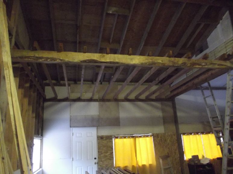 I got twelve foot long 2" by 4"s and
put up one side of the ceiling rafters, in four short sessions
some days apart because of my leg bothering my on ladders since I
did the wall insulation some months ago.
I got twelve foot long 2" by 4"s and
put up one side of the ceiling rafters, in four short sessions
some days apart because of my leg bothering my on ladders since I
did the wall insulation some months ago.
In Passing
(Miscellaneous topics, editorial comments & opinionated rants)
Iran
There are of course many and varied opinions on the
combined Israeli-American attack on Iran - its logic, its
potential effectiveness and chances it will go badly or turn into
a war of attrition with no end result. I ran across a video whose
content apparently predated the recent events but which had just
been uploaded to youtube, Why the Gulf States Fear Iran.
The reasons for fearing the aggressive Islamist regime were pretty
much those stated for making the attack: attacks by Iran sponsored
terrorist proxies Hezbollah, the Houthies and Hamas, a vast
program of missile and drone weapon production, oppression of
their own people and the nuclear weapons program. The proxy
attacks have apparently claimed 900 American lives over the years
as well as many Israelis and Arabs. If the regime had managed to
make atomic bombs they would have been in position to blackmail
and bully the whole region, if not the world. There is some debate
about how close they were, but in spite of Iran's protestations
about peaceful purposes, the only reason for enriching uranium
from U-238 to U-235 to the extent they had would be to make a
bomb. Some apparently good estimates were that they were just
three weeks away last summer, and would have already had them if
not for the strikes on their deep underground facilities at that
time, the "12 day war". And apart from that they were making
hundreds of ballistic missiles per month. By 2030 they might have
been able to strike the US East coast - with nuclear weapons - and
no one would have dared to defy them. The world would be their
hostage.
I don't think much of war as a means for solving
international problems. If, for example, the various peoples of
Ukraine's provinces ("oblasts") had been free earlier to vote for
what country they would like to be a part of (or to create),
desirable realignments would be made without fighting and no one
outside should have anything more to say about it. And so it could
potentially be in other present zones of contention. The Kurds
have long wanted their own country but they are divided among four
countries south of Lake Van, who won't give up "their" majority
Kurdish lands.
But if a rogue regime of ideologists with hatred in
their hearts is bent on imposing its will on the the the people(s)
of a whole nation and then on other nations and the rest of the
world, then it's war or knuckle under. Better that war be held
before they are ready to strike and probably bring widespread
destruction. And still better that it be done by careful target
identification than by indiscriminate destruction. That is more
possible now than ever in the past. Before aircraft, one could
only strike an enemy's front lines. Now a nation can be hit
wherever it does most damage to the regime rather than to the
whole populace. To eliminate the ruler and his supporters alone,
wherever they are, to change the whole direction of a rogue
nation's leadership, is a new experience and perhaps the new ideal
for how to wage war -- apprenhend or kill those behind dangerous
antisocial actvities rather than have whole nations suffer because
of them.
Saudi Arabia's crown prince MBS said in an interview
a few years ago that Ali Khameni was the most dangerous person in
the world. "He has a project." said MBS. "Hitler had a project,
but no one realized how dangerous he was until it was too late."
The new operation, which would normally have started
at night, went ahead immediately in the morning when it was
discovered that all the heads of the regime were holding two
meetings one morning in a facility in Tehran at the end of
February. One group was meeting to discuss war countermeasures and
the other, measures to be taken against protestors. We recall that
tens of thousands of Iranian protestors were killed, wounded and
imprisoned in the uprisings in January. The regime complained that
American sanctions were the reason for the uprisings. Did
sanctions explain why the regime was too busy building missiles en
masse and restoring its nuclear program to bother with maintaining
civilian infrastructure even for basic needs like drinking water?
This slaughter of Iranian citizens seems to have been the
proximate cause of the decision to attack at this particular time,
with the rapid buildup of forces in the region over the next few
weeks.
Doubtless the officials carried no cell phones to
betray their positions, but along with spies and satellite views,
traffic cameras everywhere permitted tracking their movements via
the internet. This seems ironic since the regime would have
installed them to monitor the movements of its own citizens.
Israel struck the meeting facility while America started in on the
military targets, and the operation was "Go". It is said that
dictator Khameni and 48 other high officials were killed. (I won't
call him either a "leader" or "supreme".) The operation thus
started by "beheading the snake" as it were. The US administration
said there were three or four persons who they had considered
might be good people to take over the Iranian government, but they
were all killed in the same strike. Later another strike killed
some remaining officials who were meeting to pick a new regime
ruler. The new ruler lasted ten minutes? Someone said they should
make an episode of "World's Most Dangerous Jobs" featuring the job
"Supreme Leader of Iran". (Was this strike a mistake? Is there
anyone left now with enough authority to authorize or organize a
surrender? It seems doubtful surrender was being considered... but
what if?)
Some commented that air strikes alone have never
brought down a regime, and that the Iranian people, however much
they might want to be rid of the Islamist regime, are unarmed and
unorganized. There is thought that units of the IRGC (the Islamic
Revolting Guard Corps-e) might decide to go over to the people's
side. Other than that, the Americans have been arming Kurdish
militias in Northern Iraq for some months. (This suggests the plan
may have been started before the January uprisings.) There is a
ground force, one that might zealously attack Iran in hopes of
creating an independent Kurdistan. American bombers have been
striking Iranian military installations along the border to open
the way for them. And just breaking as I finish up on March 5th,
Azerbaijan has massed troops along its Irani frontier and looks
poised to invade. There are said to be more Azerbaijanis in
Northern Iran than in Azerbaijan, so there is incentive. These
potential invasions were already feared by Iran and if carried out
they will certainly help defeat the regime. We can only hope the
result will be favorable to the oppressed Iranian people as well.
Scattered Thots
* It seems there's now a
"jab" for everything including some of the childhood illnesses I
had as a kid like measles, mumps, strep throat, chicken pox,
laryngitis and so on. But there's a lot of controversy over
possible negative health effects from any and all and perhaps just
from so many of these injections, especially autism, itself a
highly debilitating and apparently life long disease.
The first vaccine was for smallpox, and it saved a
zillion lives from this devastating disease. But where did it come
from? Someone noticed that people who milked cows never got
smallpox. Cows have something called "cowpox" with a very similar
virus, but it doesn't make people (or even cows?) sick. Those
exposed to the cows were exposed to cowpox and it made them immune
to the smallpox virus as well. So the cowpox virus was harvested,
and then injected into people.
But it may be worth noting that the cow milkers
became immune without a needle being shoved into their skin.
Perhaps the needle seemed like a convenient means of
administration, but obviously it wasn't a medical necessity, at
least in the case of smallpox. Should we be exploring oral or
other less intrusive means of administering vaccines?
* Ever wonder about all the extra letters in English words?
According to "Rob Words" on Youtube, the bulk of them came after
Gutenberg invented the printing press. The more I think about it,
the more I think the Flemish printers tasked with producing the
first books in English - who weren't themselves English - were
being paid by the letter. They invented the spellings with as many
extra letters as they could reasonably fit into many of the words
in order to charge more.
Since those were the first writings most English
people had ever seen, they simply accepted the spellings as being
"right" and "standard" - "set in stone" as it were. Thus we hav
"thought" instead of "thot", "could" instead of "coud", "laughter"
instead of "lafter", and countless other examples. Far more than
enuf!
Why English is full of silent letters
RobWords
https://www.youtube.com/watch?v=NXVqZpHY5R8
We also lost the letters eth (Ð, ð - as in
'the' = ðe) and thorn (Þ, þ - as in 'thin' = þin) at the same time
becuz Germans (ie, Gutenberg) don't use ðose sounds. And ðe Flemish printers
being paid by ðe
letter woud hav had no incentiv to ask ðat ðey the required lead type
symbols be cast because English needed ðem! Instead they used "TH" for
both. (But Iceland still uses ðem! I don't þink ðer ever wer
letters for ðe sounds "sh" and "ng".
Not all spelling weirdnesses wer the Flemish
printers' falt, of course. "knife" for example was originally
pronounced "kneef" with the "k". But how many words hav useless
silent letters, "k", "l", "h" and "w", even at the beginning of
the word, and an "e" for nothing at the end, that probably weren't
ther befor the printing press? It's hard to find printed texts
dating from before the printing press to compare the spellings. We
mite hav trubel reding ðem, too.
Sure enough - here's a sample, hard to read.
(But why does it look like it was done on a printer?)
(All thorns and no eths?)

* "It's not who votes that counts, but who counts the votes." -
Joseph Stalin
* "We are having a hard time getting into the offices of power,
but once we are there, we will only leave them when they drag out
our dead bodies." - Hermann Goering (From memory - probably not
his exact words.)
* "You can vote your way into socialism, but you have to shoot
your way out." - Martin Armstrong (who may or may not have been
quoting someone else) in an interesting recent interview with
Glenn Diesen on Youtube. It sounds far fetched, even crazy, until
you consider the two quotes above - and suspicious election
results in recent times in a number of countries, states,
provinces and cities.
Electrosmog Department
(I can't seem to get away from this topic, so here's it's
own place!)
I plugged in the 120 VAC heater without using the
rectifier bridge adapter cord I had made, thinking "It probably
doesn't really help." That night my tinnitus was definitely worse,
to the point where, having woken up but forgotten about the
adapter, I started thinking about what it might be. Then I
remembered. It does make a difference after all!
On a later occasion, I forgot that the adapter was in
front of the power cord, I unplugged the heater and plugged in a
fan to help dry my ceiling lumber, set spaced apart on a table.
(after having left it in the trailer in the rain for some days
when I bought it.) The fan wouldn't run and I wondered what was
wrong with it. Oops, the fan didn't like DC power.
Another night I forgot to turn off the computer. That
was no help either. It's so quiet (except electricly), and once
the display goes off, there's only a couple of dim indicator LED's
in inconspicuous places to show that it's on. Dang, did it
again... and again! I wake up wondering why I'm getting no relief.
(Also the dang thing sometimes turns the bluetooth and wifi back
on when it boots up - usually whenever I forget to check. Why
can't it just leave them off if I've turned them off? And what is
the point of wifi with its microwave emissions when there's an
ethernet connection to the internet?)
When I do get sufficient (never complete!) relief
from the high pitched tinnitus, the loudest of the CW stations,
heard as Morse code in my head at lower audio frequencies, become
prominent and annoying. I believe these are probably LF or ELF
radio transmissions - most likely marine weather reports keyed by
computer seemingly 24/7 instead of by hand - and they seem to cut
through any amount of shielding without notable attenuation. I
wonder if I'd still hear them if I went deep underground? But I
don't know where there's a cave, mine or other such place around
here.
ESD
(Eccentric Silliness Department)
* Dictatorship - Captain Richard, the head potato, is in charge of
the vessel.
* Seed - Past tense of "see". "I seed that movie last week."
* Saw - Device for cutting. "I will saw that movie."
* Was - Backstroke of saw cut.
* Sod - Past tense of "saw". "Was crappy movie, so I sod up the
film."
"in
depth reports" for each project are below. I hope they may be
useful to anyone who wants to get into a similar project, to glean
ideas for how something might be done, as well as things that
might have been tried, or just thought of and not tried... and
even of how not to do something - why it didn't work or proved
impractical. Sometimes they set out inventive thoughts almost as
they occur - and are the actual organization and elaboration in
writing of those thoughts. They are thus partly a diary and are
not extensively proof-read for literary perfection, consistency,
completeness and elimination of duplications before publication. I
hope they may add to the body of wisdom for other researchers and
developers to help them find more productive paths and avoid
potential pitfalls and dead ends.
Electric
Transport (No
Reports)
Other
"Green" & Electric Equipment Projects
Open Loop Air Heat Pumping (OLAHP)
Indoor-Outdoor Air Heat Exchanger
[10th] Some days I 3D print a baffle box or two, somedays not. I
ordered a higher temperature printing plate for the Creality K1C.
It arrived, so I decided to try the new higher temperature
polycarbonate (PC) filament. Let's see: 240+° extruder... 100+
° bed... and WHAT? 10 mm/second print speed
"for good inter-layer adhesion"!?! That's a far cry from 80 mm/s
for PLA or 50 MM/s for ABS!
Let's see: print time 5 times longer is almost 18
hours! (And that was after fixing it... Cura slicer automaticly
changed the layer thickness on me from .4 mm to an incredibly fine
.1 mm when I selected "PC". I didn't understand why the file was
3-1/2 times larger until I noticed it said the print would take
over 3 days!) There's no way I'm going to be able to
monitor it while it's printing. Putting it on this evening means
it'll be done... about suppertime tomorrow! I guess I'll just have
to trust it. 3 hours later when I went to bed it was almost
finished the first layer.
Printing two dozen baffle boxes is already taking
forever. I'm up to about 20. This will probably be the only one
done from PC, no matter how great it is!
[13th] I 3D printed the "U-turn" end box. It took
6 hours and I was up really late for a second night. (Must start
these long prints before evening!) I found a tiny circular
grinding wheel for my "dremmel" and it seemed to clean the inside
of the ends of the small copper "U" pipes okay. The hydrochloric
acid didn't seem to be the whole answer. But I can see the
cleaning and soldering of the pipes is going to be a tedious
process. And I'll have to check each of the 14 radiator pipes with
"U"s for leaks before I combine them into one with manifolds.
[18th] I broke,
ripped and pulled two inches of fins off each end of one of the
radiators. That gives the pipes some flexibility at the ends for
imperfectly matching end pieces. The pipes seem to be annealed
(soft) copper. I noted there were some dents in them, then
realized I was making them with the pliers as I worked. I tried
bending the end of a pipe over a little bit and it went easily
enough.
I cleaned the pipes at one end with fine sandpaper,
but I wasn't very happy with the result. I shouldn't have done the
slight reaming when I had initially cut the end pieces off,
because it kept the sandpaper away from the very ends that needed
soldering. I tinned one and the solder didn't flow smoothly. I may
have to cut 3/8 inch of all the pipe ends and pull out a few more
fins.
(Then I got heavily into the battery project and this one sat
again!)
"Faraday
Cabin" Construction
[15th] I put up one 2 by
4 (actually two, 8 feet long, as I didn't have a 16 footer.) on
one of the walls to set the ceiling rafters on top of. Then the
first end rafter screwed to the wall and running to the middle of
the 6 by 6 beam half way across.
[19th] I put up 5 more ceiling rafters. My left leg is bothering
me. Ever since doing all that wall insulation months ago, climbing
ladders has hurt tendons or something in the upper part and every
time I go up again, it aggravates it. Like the tennis elbow that
lasted a year and even now can still be felt again if I use a
staple gun [CLACK! CLACK! CLACK!], it shows no signs of going away
any time soon and is even bothered by stairs.
So I've been trying to stay off ladders or at least
minimize it. The 15th aggravated it. But of course, nothing gets
done without doing it, so I'll just try to keep it to a minimum.
Otherwise I'd probably have done all 12 rafters on the one side in
a day.
[22nd] I put up four more rafters, again a short session ending
Before my leg might start acting up.
A couple of days later I put up the last ones to
finish it.
Kitchen Hot Water Systems
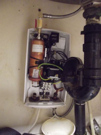 Hot water
took almost a minute to come from the water tank across the house,
so I installed a 3 KW "on demand" hot water heater under the sink.
(The 240 V wire was already under the sink for a heater I never
used.) But the design seems senseless. The instructions say to
install the unit as close to the hot water tap as possible. But it
sabotages its own instructions. The hot water tap is usually the
left knob, so the heater goes under the counter to the left of the
sink. To reduce the distance and get hot water fastest, the "hot"
outlet obviously should be at the top right of the unit.
Instead, a pipe runs through the unit from the top to the bottom
and comes out at the bottom left. That's about a foot of extra
pipe. Then there needs to be another foot to go back up, and an
extra six inches to go from the left side of the unit instead of
the right side. That's an extra 30 inches of pipe.
Hot water
took almost a minute to come from the water tank across the house,
so I installed a 3 KW "on demand" hot water heater under the sink.
(The 240 V wire was already under the sink for a heater I never
used.) But the design seems senseless. The instructions say to
install the unit as close to the hot water tap as possible. But it
sabotages its own instructions. The hot water tap is usually the
left knob, so the heater goes under the counter to the left of the
sink. To reduce the distance and get hot water fastest, the "hot"
outlet obviously should be at the top right of the unit.
Instead, a pipe runs through the unit from the top to the bottom
and comes out at the bottom left. That's about a foot of extra
pipe. Then there needs to be another foot to go back up, and an
extra six inches to go from the left side of the unit instead of
the right side. That's an extra 30 inches of pipe.
When I put it in around 4 years ago I was unaware of
just how much the extra piping would affect things. It was awful.
It took about 20 seconds for the first hint of warmth to come
through, then it gradually heated up to a working temperature over
the next minute or more. Since the heating power was a constant 3
KW, the slower the flow, the warmer the water is. It's a painfully
slow flow for washing dishes, and after each adjustment it took 20
seconds to start feeling any change in temperature. And if one
slows it a bit too much, the heater shuts off and after 20 seconds
the water comes out cold, then it's another 20 seconds to start
getting warm again.
One day this month, I finally had had enough. I took
out the unit and cut off the pipe going down so the water came
from the top. I threaded the tank itself for 1/8 inch pipe thread,
soldered that pipe nipple to a little shutoff valve that happened
to fit it, and got a couple more fittings to go to a hose fitting
to the Hot tap. The hose was just long enough to use without extra
pipes (by moving the unit to the right of where I actually wanted
it).
To my surprise, it still takes 20 seconds before the
water isn't cold! It does at least heat up to a working
temperature in another 20 seconds instead of a minute or more.
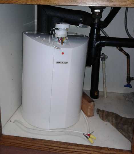 My previous solution of
a small (15 L?) water tank under the sink worked much better
except that my well water reacted with the heat and the zinc anode
rod to make a terrible stench every time I turned the tap on. Hot
water took just a few seconds and had as much flow as desired.
Unless your water doesn't cooperate, it's the way to go. At the
time I considered putting a rainwater barrel on the roof just to
feed this tank. [TE
News #132 - scroll down a bit from link]
My previous solution of
a small (15 L?) water tank under the sink worked much better
except that my well water reacted with the heat and the zinc anode
rod to make a terrible stench every time I turned the tap on. Hot
water took just a few seconds and had as much flow as desired.
Unless your water doesn't cooperate, it's the way to go. At the
time I considered putting a rainwater barrel on the roof just to
feed this tank. [TE
News #132 - scroll down a bit from link]
In addition to it being a tank, I ran it off the 36
volt DC solar system. I used a 36 volt element, but I turned it
from 1200 W to 400 W to under 200. I think one could just use the
tank's original 120 V / 1200 W heater element (120 W at 38 volts)
as long as one doesn't use up the water doing dishes. If you use
it all it will take a long time to heat up again. OTOH it's pretty
easy on the battery. (IIRC I didn't have a very good battery at
that time.)
The tank didn't use much power keeping itself
warm - it was mostly just heating new water after some was used.
Haida Gwaii Gardening
(Short Report)
I fertilized my fruit and nut trees and berry bushes
with my woodstove ash shovel. For the trees, 3 big scoops of
woodstove ashes (potash - potassium), 1 small scoop of bone meal,
1 large scoop of "lawn and garden lime". Nitrogen in liquid form
on other occasions. Then I scratched up the dirt around the trees
to get the fertilizer going in, and put down pieces of cardboard
to keep the weeds down near the trunks. Same but less on each
berry bush - blueberries, josta berries and black currents. The
jostas have grown into pretty big bushes now, taller than me.
Josta berries are akin to black currents but substantially larger
- more like small grapes.
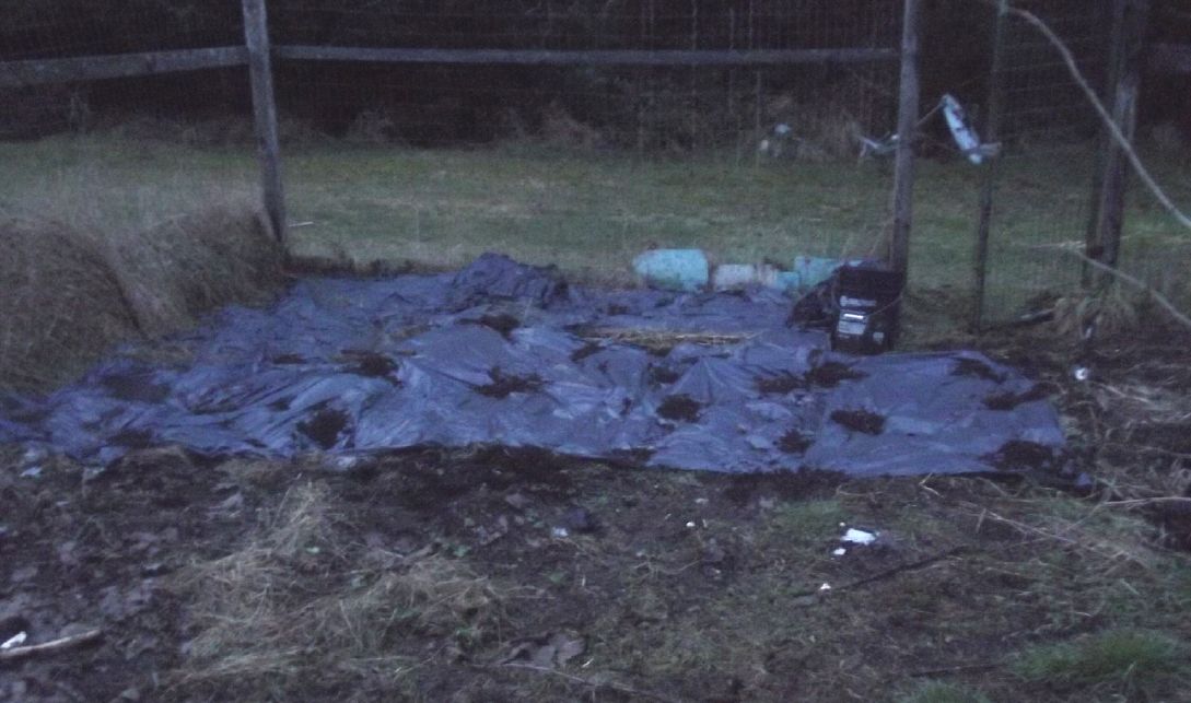 I started putting down black plastic
(garbage bags, cut open) on the ground in the main garden to try
to kill the weeds. (The weeds were SO bad last year! They wrecked
all my root crops.) The idea of black plastic is that the sun
heats the dark plastic and so the soil beneath, and the heat
encourages the weed seeds to germinate. But it also blocks the
light so the seedlings die.
I started putting down black plastic
(garbage bags, cut open) on the ground in the main garden to try
to kill the weeds. (The weeds were SO bad last year! They wrecked
all my root crops.) The idea of black plastic is that the sun
heats the dark plastic and so the soil beneath, and the heat
encourages the weed seeds to germinate. But it also blocks the
light so the seedlings die.
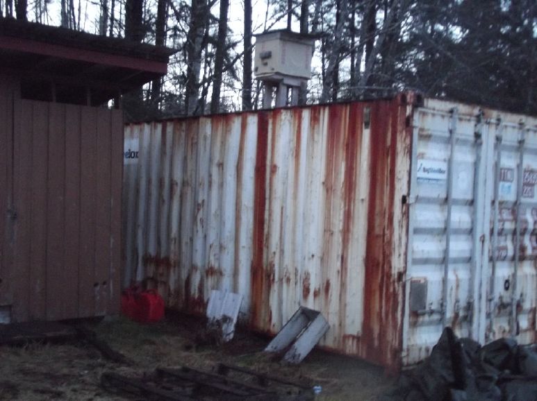 I put my beehive on top of my
shipping container. I think that bees like it up high and there's
a better chance of it being adopted. I've certainly had no success
so far. The big consideration is that there's no way I'm going up
there! Maybe in winter at night. They don't like vibration and
walking on that roof it's unavoidable. I don't want to have to run
from a beehive from on top of a roof! So basicly it'll just prove
or disprove that bees will like it better than wherever I've been
putting it so far.
I put my beehive on top of my
shipping container. I think that bees like it up high and there's
a better chance of it being adopted. I've certainly had no success
so far. The big consideration is that there's no way I'm going up
there! Maybe in winter at night. They don't like vibration and
walking on that roof it's unavoidable. I don't want to have to run
from a beehive from on top of a roof! So basicly it'll just prove
or disprove that bees will like it better than wherever I've been
putting it so far.
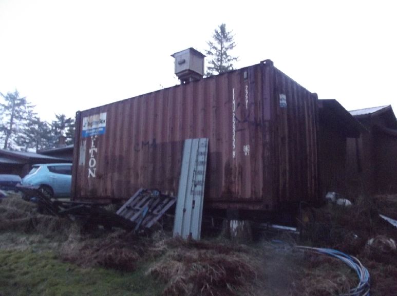 This shows better how the area is
pretty open for bees to fly to and fro. IIRC bees will forage from
up to 10 miles from the hive.
This shows better how the area is
pretty open for bees to fly to and fro. IIRC bees will forage from
up to 10 miles from the hive.
(In going up there I threw down a ripping plastic tarp and some
old palettes that the tarp was on top of. These were supposed to
keep water off the roof to keep condensation from dripping off the
roof inside. It worked poorly enough when the tarp was whole; now
all it was doing was trapping water and making it rust worse on
top, with no effect on the drips inside. Plastic tarps just don't
last long! Nor does running a vent fan stop the drops from forming
under the ceiling.)
New Battery R
& D
A Recap: The Everlasting Zinc Electrode
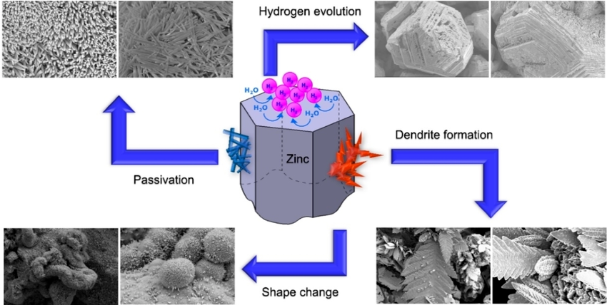
I ran across this picture showing the challenges of making a
rechargeable zinc electrode - the challenges I've solved.
So I thought I'd go over them again:
1. Passivation normally
occurs when the zincate ions formed during discharge spontaneously
turn into zinc oxide on the separator sheet and clog it up so the
electrolyte ions can't pass. Osmium is a powerful catalyst. The
film of osmium doped acetaldehyde on the surface of the separator
sheet prevents the zincate ions from changing to oxide there.
2. Hydrogen Evolution can occur during recharge because
the reaction voltage of zincate ions to metallic zinc is a little
higher than the reaction voltage of water into hydroxide ions plus
hydrogen gas. There are a number of "hydrogen overvoltage raising"
additives to zinc to help prevent this gassing. I use .5% (or
more) of zirconium silicate powder, which seems especially
effective. Aside from water loss, zinc hydride seems to be formed,
which deteriorates the electrode. (or is it passivated zinc
oxide?)
3 & 4. Shape Change and Dendrite formation. Dissolved
zincate ions can pass the separator sheet and the dendrites formed
on recharge connect between electrodes and short out the cell.
This is the usual way zinc and also cadmium cells die. When such
dendrites form in lithium cells the short circuit can cause fires
and explosions.
In my cells these simply don't matter. When the zinc
dissolves to zincate ions during discharge, it can't pass through
the sodium dodecylbenzenesulfonate in the separator sheet to the
other electrode, or convert to passivated zinc oxide per #1 above.
It all stays somewhere inside the zinc electrode, as conductive
zincate ions. And the electrode has sufficient space in it to hold
all the zinc or zincate with room to spare. All the plating back
to zinc around the current collector wire will occur within the
electrode space in whatever crazy shapes and forms it likes.
Notes:
(1) My electrolyte is around pH 13 . KCl (10%) plus NaCl (?%) with
a minimum of KOH (5%) is used to achieve this. Zincate won't form
in a lower pH, but 13 is a lot less caustic than 14. It needs the
potassium for zincate. (NaOH should work too)
(2) With the change from "flooded cells" to "dry cells" around
mid-month this very month, the zincate ions are likely to hang
around the electrolyte wetting the strands of cotton batten that
loosely fill the space, and recharge to zinc on and around those
strands, with the zinc on the strands connecting to the copper
wire current collector/terminal.
As a further interesting aside to #2, hydrogen
evolution: manganese, with its somewhat higher reaction voltage
than zinc (~ -1.5V vs -1.2V), normally converts spontaneously from
manganese metal to manganese hydroxide in water, bubbling hydrogen
- no electricity needed. To get the manganese to remain metallic
and to recharge from Mn(OH)2 to metallic, I added two overvoltage
raising additives: 1% antimony sulfide and 3% zirconium silicate,
at pH around 12 to 13. (I didn't get it to work at pH 14.) As far
as I know, no one else has ever managed to get manganese to stay
in (or recharge to) metallic form in an aqueous electrode, so I'm
rather proud of this, even if zinc is probably going to
effectively have more watt-hours per gram in practice. (Preventing
the current collector and terminal from bubbling hydrogen was a
challenge I didn't overcome. I think it's doable. A 2.2 volt
nickel-manganese "moderately alkaline" cell would be cool!)
Organic Monel/Copper Electrode
The organic copper electrode substance (as fried
beans/monel powder mix - monel being a nickel-copper alloy) seemed
to have some very unusual properties. After my success using the
original mix from (?)2008, I made the new mix without the
"superfluous extras". But it didn't seem to perform. Instead of
charging up, it seemed to get weaker fast with each attempt to
charge and discharge. So had the cupro-nickel sheet metal in
various experiments a year or two back, which always initially
performed fabulously with high current capacity.
 [7th] As the electrode substance wasn't well
compacted I redesigned the cell with a double wall basket, both
layers perforated, with the separator paper protected between the
two layers. The intent was to compact the substance with the
basket itself in place instead of using the steel sleeve and then
replacing the sleeve with the basket. The outer wall would protect
the paper while the inner wall would prevent the paper from
getting pushed in by electrode powder squeezing through the outer
perforations. I cut the original paper so there was no overlap at
the ends, aligned the seam with the short unperforated section
(new design) so nothing would get through, and slipped the outer
wall sleeve over it. Sizes for the space between the baskets was
just an estimate, but it seemed like a pretty good fit for the
paper - not too tight, not really loose.
[7th] As the electrode substance wasn't well
compacted I redesigned the cell with a double wall basket, both
layers perforated, with the separator paper protected between the
two layers. The intent was to compact the substance with the
basket itself in place instead of using the steel sleeve and then
replacing the sleeve with the basket. The outer wall would protect
the paper while the inner wall would prevent the paper from
getting pushed in by electrode powder squeezing through the outer
perforations. I cut the original paper so there was no overlap at
the ends, aligned the seam with the short unperforated section
(new design) so nothing would get through, and slipped the outer
wall sleeve over it. Sizes for the space between the baskets was
just an estimate, but it seemed like a pretty good fit for the
paper - not too tight, not really loose.
 I 3D printed a little cone to sit on
top of the basket, to prevent outer electrode substance from
getting into the basket when I tried to fill it.
I 3D printed a little cone to sit on
top of the basket, to prevent outer electrode substance from
getting into the basket when I tried to fill it.
 I took the original substance and
added some water. My intent was for it to settle and then pour off
the water. However the bean substance didn't want to settle. The
monel powder was a layer at the bottom of the beaker. I put some
heat under it and evaporated off the excess water, stirring
occasionally to mix it together again.
I took the original substance and
added some water. My intent was for it to settle and then pour off
the water. However the bean substance didn't want to settle. The
monel powder was a layer at the bottom of the beaker. I put some
heat under it and evaporated off the excess water, stirring
occasionally to mix it together again.
The silver current collector was coated with black,
some of which flaked off when the sheet was bent.
[8th] It was still a paste and I pasted some of it all over the
outside of the basket, then put the basket into the cell. Then I
put the cone over the basket and started spooning in more of the
paste. It didn't even come close to filling the space. As I
suspected, it must have not been well compacted before. I mixed
another 10 grams of the bean/monel powder with .55 grams of sliver
oxide (~5%) and scooped that in too, again compacting whenever I
added some more. That was theoreticly 40 grams now, but some had
probably been lost so call it 35. So probably around 14 amp-hours
- an absurd amount of substance to match with 4 amp-hours (5
grams) of zinc. It still didn't reach the top. I wrapped in a thin
sheet of plastic to occupy the remaining space, then the thick
cover ring. Hopefully it is well compacted and even filling in the
outer wall's perforations.
An initial discharge looked promising, but it quickly
deteriorated like the previous times, well compacted or not.
[9th] Further tests went just as badly, with the cell showing
seconds of capacity under a 25 ohm load instead of hours, at ever
decreasing voltages. I left it just sit for a couple of hours and
the load voltages came up. But still just seconds. There is
something very strange about copper's electrochemistry! I let it
sit overnight.
[10th] In the morning the voltage was .3 something. No point
trying even a brief load test. I decided to try charging at just
1.20 volts instead of 1.5 or 1.6, in order that the copper should
only charge to valence 1 or 2 instead of 3 - theoreticly insoluble
CuOH or Cu(OH)2 and not the probable soluble ion. Charge current
started at 4 mA and went down from there.
[11th] Racking my brain for some answer, I went on line and looked
at a paper about copper surface oxidation and reduction with a
voltage sweep (around -1.0 to +1.0 V) and fancy equipment. One of
their conclusions was that it was complicated.
But I finally thought about concentration of baked
bean stuff to monel and silver. If there was too little bean, it
wouldn't chelate the soluble copper ions. If there was too much,
it would hold the monel particles apart and they wouldn't make
contact with the silver and with each other. That could explain
the poor performance better than, or in addition to, insufficient
compaction. The organic matter held the metallic particles
separated no matter how hard it was compacted. At least, within
reasonable compaction limits.
The proportions might be fairly critical. I had
originally used 50 grams of monel to 20 grams of beans. The dense
monel (~8 g/cc) was the bulk of the weight but the beans (~1 g/cc)
were the bulk of the volume.
 I emptied out the cell again. The
substance seemed well compacted this time and it took some time to
scrape it all out. Much was stuck to the basket, including (as
intended) in the perforations. I weighed the substance scooped out
along with the remainder in the container and threw in the rest of
the silver oxide, about .45 grams. That was about 39.25 grams. At
the risk of possibly going too far, I added 40 grams more monel,
doubling the overall weight. Now it was 90 grams of monel to 20
grams of beans. And maybe 2-1/2 or 3 grams of silver oxide. Not
5%. But I'm not going to set up and then wait days for more silver
oxide to form, so it'll have to be 3% Ag at best.
I emptied out the cell again. The
substance seemed well compacted this time and it took some time to
scrape it all out. Much was stuck to the basket, including (as
intended) in the perforations. I weighed the substance scooped out
along with the remainder in the container and threw in the rest of
the silver oxide, about .45 grams. That was about 39.25 grams. At
the risk of possibly going too far, I added 40 grams more monel,
doubling the overall weight. Now it was 90 grams of monel to 20
grams of beans. And maybe 2-1/2 or 3 grams of silver oxide. Not
5%. But I'm not going to set up and then wait days for more silver
oxide to form, so it'll have to be 3% Ag at best.
[15th] It didn't work any better. I know that the cupro-nickel
sheet metal worked great at first making copper a highly promising
chemistry. I decided to try one more time with the monel powder.
This time I scooped out the cell and had 20 grams of guck. To this
I added a whole 50 grams of monel powder, making 70 grams of
mostly monel powder. But it still didn't seem to work any better.
I can't help but think I'm missing something simple. but I can't
figure out what it is. [Much later: It was the zinc electrode!]
The NickelManganates-Zinc Dry Cell
[16th] At this point, barring any further inspiration on copper
& its hydroxides, I decided to try nickel manganates for the
"+" electrode again. AKA nickel-manganese oxides, typicly NiMn2O4,
then maybe reducing to something like NiMn2O3OH
then probably NiMn2O2(OH)2, maybe
NiMnO(OH)3 and maybe even NiMn2(OH)4
-- at undetermined voltages.
The voltage didn't seem to be the voltage of nickel
oxyhydroxide as I had for so long been so sure it should be, thus
causing myself much grief and thinking some probably good cells
were failures. (as discussed in TE News #175) The first reduction
may or may not be the same as the voltage of manganese dioxide
(MnO2 => MnOOH = +.15V @ pH 14) and the voltage of
each reduction-oxidation ("redox") change is probably a little
lower than the first. It's the zinc (Zn => Zn(OH4)--
= -1.28 V @ pH 14) that provides most of the cell's voltage.
I searched the cupboard and found a nickel manganates
mix I'd made in December 2022, Flooded with acetone and mixed to
dissolve and combine the ingredients as "epitaxial" crystal forms.
No doubt silver powder would be better than graphite powder or
CCB, but this mix is all ready to go, and no more silver oxide
powder is presently on hand. There was a good amount of it for a
few ointment jar cell experiments. (TE News #175 - it isn't clear
in that which mix of the two was actually used, but either one
should work. Evidently I bleached it, which should have
oxidized/pre-charged it.)
I decided to leave the much reused cell with monel
alone and do an all-new cell for this. (Maybe I'll think of
something that will get the copper/monel to work?) So I 3D printed
the internals for a new cell per the latest designs and re-did the
zinc electrode and the separator paper as well. And I made a
taller cover cone with a deeper bottom recess. The first one kept
coming off and much powder accumulated on top of it without
wanting to go down the slot.
Then I thought about the outside current collector.
I've been wanting to plate a thin layer of silver onto graphite
gasket sheet for that. I bought sodium thiosulfate for it. I
looked up instructions online. I also needed sodium metabisulfite,
which I should have ordered with the thiosulfate. (I thought of it
in the next day or so.) I thought I could just get some out of a
wine making kit. I opened one, but the package just said
"sulfite". That wasn't very reassuring as to composition, much
less purity.
Also I needed silver chloride. I could make that from
silver, nitric acid and hydrochloric acid. It started to sound
complicated. I went to the SigmaAlderich website and ordered a jar
of each. The silver chloride wasn't cheap. Silver plating seems to
be getting to be a costly endeavor - mainly for the silver
content.
In the meantime, I annealed and flattened another bar
of silver to fit into the ointment jar and use that for this cell.
I annealed it 3 or 4 times and ran it through the mill until it
was over a foot long. (If I had rolled it that thin the first time
I wouldn't have needed to use two more bars!) I annealed it one
more time so it would be soft to mold into shape.
I made the new cell with a graphite gasket piece to
use up space around the outside, then a loop of the silver sheet,
and the new plastic stuff and the paper, osmium doped on the
inside only. I compacted down 10 grams of the substance from
December 2022. But I didn't make a new zinc center electrode. I
just took the one with the rolled up zinc sheet since it was so
easy to move it from one cell to another. I charged it at 1.5
volts overnight.
As I went to bed it occurred to me that even with 5%
silver, the monel/copper cell didn't have anything like enough
conductivity additive. Maybe 20 wt% graphite powder would be a
good additive.
 [17th] It worked marginally better than the
monel/copper cell. That is to say, tens of seconds of charge at
collapsing voltage instead of hours of steady running. The only
cell that had worked well was the one with the commercial dry cell
nickel electrode substance. Same zinc center. WAIT! It Wasn't the
same! It had zinc powder. Now I was using the rolled-up
zinc sheet electrode, in all my new attempts. Was that the key
problem? "Standard" dry cells use sheet zinc. Doesn't it discharge
to dissolved zincate ions leaving fresh surface to react? But
alkaline dry cells use powdered zinc.
[17th] It worked marginally better than the
monel/copper cell. That is to say, tens of seconds of charge at
collapsing voltage instead of hours of steady running. The only
cell that had worked well was the one with the commercial dry cell
nickel electrode substance. Same zinc center. WAIT! It Wasn't the
same! It had zinc powder. Now I was using the rolled-up
zinc sheet electrode, in all my new attempts. Was that the key
problem? "Standard" dry cells use sheet zinc. Doesn't it discharge
to dissolved zincate ions leaving fresh surface to react? But
alkaline dry cells use powdered zinc.
I broke open an old alkaline "D" cell and scooped
some of the zinc powder from its "pouch" into my new cell. Eureka!
Now it performed! It held over 1.4 volts no load, and would
deliver ~30 mA into a 40 ohm load at 1.25 to 1.325 volts. In fact
it started near the lower figure and rose 75 mV to the latter as
it ran. If I increased the load the voltage dropped. At 12 ohms it
was under a volt. But back to 40 ohms, the voltage went up to 1.3
again. In a load test, as the voltage dropped, pushing into the
zinc with a stick to move it around it changed and often increased
the voltage. Still it gradually got lower and couldn't be brought
back up as high, only to "better than it was before stirring".
[Note March 4th] It occurs to me now that if only the surface
layer of the zinc is reacting, even with zinc powder it may
explain why the amp-hours of my cells has been much lower than the
theoretical value. If that's true it's not the "+" material but
the zinc "-". But the cells improve with cycling, suggesting that
the zinc gradually gets more surface exposed as it is charged and
discharged.
I suspect that if I get it all "perfect" I'll find a
fully charged nickel-manganates/zinc cell delivers about the same
voltages as manganese/zinc: 1.5+ V open circuit and a little less
under load. But it's rechargeable. This works much better than the
exact same substance trying to charge it at 2.0 volts to nickel
reaction voltage and messing everything up with the higher voltage
reactions. I can only wonder why I was So sure for so many years
it was supposed to have that voltage. [Looks more like it's only
about 1.3 volts for the cell - less under load, which makes the
"+" side only about +.1 volts.]
As the charge drops I suspect NiMn2O4 will drop to
NiMn2O3OH and then NiMn2O2(OH)2, moving at least two electrons
without too much voltage drop. And then it might still have the
charge to go to NiMn2O(OH)3 and move another electron, probably at
a cell voltage of 1.0 or less. Going to NiMn(OH)4 might be a bit
of a stretch. But who knows?
Sure enough, after a couple of hours charging at 1.55
volts, it dropped a bit then stayed at 1.507 until I connected the
42 ohm load. Then it started out just below 1.4 volts and
gradually dropped to 1.33 over 1/2 an hour. Then I put it back on
charge. The liquid water is gone and it's running as a "dry cell".
If these are to be produced as dry cells (which could be nice),
I'll have to re-think the layout of the zinc electrode space,
because the zinc is at the bottom and there's not much electrolyte
in contact with the basket perforations. I could fill the whole
space with zinc powder? (Then is there room for the zincate ions?)
Dry Cell!
[18th] I did a 2 hour load test with 45 ohms. It went from a
little over 1.3 volts to 1.00 over that time, delivering about 65
mA-Hours. I kept stirring the zinc around and the voltages kept
changing, but the general drop in voltage was consistent overall.
Obviously it's the zinc side that makes the main difference -
works or doesn't work - not the plus side. (Although which side
was discharging to cause the dropping voltage over that time is
unsure. In retrospect, I should have put in some more dry cell
zinc to see if the voltage came back up or kept dropping.)
It has been bothering me that the zinc basket has
just a little zinc powder in the bottom and is mostly empty space.
I hadn't filled the cell with much liquid, making it more of a dry
cell. How much capacity is being lost owing to that? I have been
thinking of it needing to be a flooded cell in order that
electrolyte ions from levels towards the top be able to go through
the separator sheet and access the zinc. What good is having
perforations going up the sides of the basket unless the basket is
filled with liquid?
The dry cell zinc made me start thinking of filling
up the basket with some sort of filler. Maybe more zinc would be
overkill, so what about something that was just inert filler, not
an active ingredient?
Hmm, What about polyester fiberfill
or something? I still had some in a plastic bag left over from a
pillow filling project with my mom in some past age... It looked
rather coarse. I got out some little balls of cotton swabs
instead. Considerably finer and more "filled in".
I turned the cell upside down and dumped out the dry
cell zinc stuff, then rinsed the cell (ie, the inside of the
basket) in the sink. I cut a couple of the cotton balls open and
poured 5 grams of zinc powder on the open faces, and placed a
copper wire on top. They spilled as I tried to load them into the
cell/basket. I cut a third one in half and put the two halves over
the open balls with the zinc. This way they went in without
spilling much. Somehow the little wad pretty much filled the
basket. I neglected to add the 1/2% of zircon to reduce hydrogen
evolution. (oops)
Now I could (and did) just moisten
the cotton fluff and have interaction all the way up the up the
sides of the basket. Presto, a proper dry cell! It didn't need the
extra weight of water to flood the almost vacant basket. A dry
cell that can be used in portable equipment is of course
preferable to a flooded cell that needs to be be kept upright.
Suddenly I had in principle a high energy, everlasting battery for
virtually any use. They could be made in typical dry cell sizes or
big enough for electric cars & grid level energy storage.
Now I have to get them to deliver their full rated
amp-hours instead of an inexplicably small fraction. Certainly
having the whole basket perimeter in use will help. I turned the
charge back to 1.5 volts and left it on for the night.
[19th] Changing out the commercial dry cell zinc for fresh zinc
powder seemed to reset things back to square one. It wouldn't hold
a charge. At first it dropped to a low voltage in a minute, but
gradually it started taking longer and longer. No doubt this is
because the zinc was just loose powder without any particular
conductivity between particles. The answer seemed to be the same
as always: discharge the cell down to a low voltage and recharge.
As the zinc dissolved to zincate ions in discharge re-plates onto
the copper wire and onto itself during recharge, unconnected
particles gradually become interconnected by fresh zinc and are
then available for the next discharge. (I still don't understand
why sheet zinc doesn't work. And the re-plating doesn't work as I
expect either - too long a charge makes for lower initial
discharge voltages.)
I imagine that with the cotton batten loosely filling
the space, a network of zinc lines will be formed along the
fibers.
I also imagine that if I had added the zircon powder
it would probably charge better. I decided to redo it. (ug - reset
again!) Come to think of it, overcharging might make it worse by
the zinc bubbling hydrogen. Some of the zinc would turn to hydride
(ZnH2, or to ZnO?), and trapped bubbles would block the
electrolyte. Along with adding the zircon I turned the charge
voltage down to 1.4 volts to reduce the potential for gassing.
I pulled the copper terminal/current collector wire
out of the old cottons. It came out roughly, and I found it plated
with zinc in a couple of places but not in others. Pretty uneven.
The roughness was probably more loosely attached zinc "dendrites"
breaking off as I pulled. I expect that after much use there'll be
'threads' of zinc running all through the cotton wads and they
won't come off the wire except in little bits, or with the zinc
attached.
[20th] Well, the cotton batten idea seemed to be a failure. It
just wouldn't charge up. Next plan?
 Then I thought of filling the space
with sand. Kind of heavy, but it might work. I had some fine sand
casting sand, which I washed the clay out of. I decided to put the
zinc in cylindrical form right around the copper wire and the sand
filling the rest of the basket on the outside. I used a brass tube
(5/16") and a funnel to put the zinc in, then filled with sand
around it and removed the tube. It ended up with about 13 grams of
sand. To finish filling the zinc space it needed 11 grams of zinc
powder (total. theoretical 9 amp-hours - mixed with a trace of
zircon powder). It didn't work right away but looked promising.
Then I thought of filling the space
with sand. Kind of heavy, but it might work. I had some fine sand
casting sand, which I washed the clay out of. I decided to put the
zinc in cylindrical form right around the copper wire and the sand
filling the rest of the basket on the outside. I used a brass tube
(5/16") and a funnel to put the zinc in, then filled with sand
around it and removed the tube. It ended up with about 13 grams of
sand. To finish filling the zinc space it needed 11 grams of zinc
powder (total. theoretical 9 amp-hours - mixed with a trace of
zircon powder). It didn't work right away but looked promising.
 The lids
didn't fit right. I covered the top of the cell with modelling
clay so it wouldn't dry out. No doubt it's better, at least
initially, to have the zinc powder crammed in around the wire than
loose and more dispersed.
The lids
didn't fit right. I covered the top of the cell with modelling
clay so it wouldn't dry out. No doubt it's better, at least
initially, to have the zinc powder crammed in around the wire than
loose and more dispersed.
[21st] I let it discharge overnight (12 ohms). In the morning it
was still putting out a few milliamps at a few millivolts. After a
half hour charge at 1.50 volts it was working pretty well, holding
over 1.1 volts with a 32 ohm load and 1.0 volts with 12 ohms. YAY!
It was charging at a pretty low rate (soon under 10 mA) so it had
to charge many hours before a long load test. I did one late in
the afternoon, 37 ohms. By then the charging was below 3 mA. It
was near 1.4 volts open circuit. The test started at 1.15 volts
but ran only 25 minutes, down to below .9 volts. But I figure the
zinc needed another discharge and recharge. So after 25 minutes I
changed it to 10 ohms. I took a few more readings in the .6xx volt
range then left it going.
[22nd] After charging overnight it still didn't seem to work very
well. Load voltages started too low and dropped rapidly. After 14
minutes of load test I disconnected it and pulled the (modelling
clay) lid off. It looked a bit dry. I squirted in a cc or so of
water and a little sat on top as liquid. That gave me a chance to
dab in a bit of pH paper for a pH test. It was really low, 8 or 9.
Perhaps the electrolyte hadn't had time to diffuse up, but that
seemed really bad. I set in 1/2 a gram of KOH flakes on top of the
sand to soak in. A second test a little later was somewhat better,
starting at over 1.2 volts instead of under 1.15 . I let it charge
until almost 2 PM, then tried again. Now it was over 1.275 volts
for the first few minutes. I only ran it 17 minutes and then back
on charge. By 5:20 PM charge current was down to 1.3 mA. That
seemed good because it meant it wasn't bubbling hydrogen once the
zinc was charged. (At least, very little.)
I ran another load test and got the best result yet:
over 1.275 volts for 14 minutes and over 1.250 for 25 minutes, all
at 39 to 38 mA. Then I cut it off to come to the computer and
write about it. (All these tests with 32 ohms load, BTW: 30 ohms
resistors and 2 ohms in the milliamp meter shunt and test leeds.)
While it was well charged I tried a short circuit. It
only put out 400 mA, but there was little fade, with it still
putting out 380 mA after about 15 seconds.
Key findings are that the sand with the zinc powder
in the center worked well, and that one must be sure in all the
changes, disassemblies and reassemblies and "toppings up"
with water that there's still enough electrolyte with enough
alkali in it so that the zinc can form zincate ions.
And if I may be so bold without running it for a
month or more, or even having done an hours long discharge test
yet, it appears nickel-manganates makes a great rechargeable plus
electrode for a NiMn-Zn cell that would probably be rated as 1.2
volts.
A 2 hour load test in the evening seemed about as
strong as the previous test. As the time wore on, the voltage
gradually dropped, finally to about .8 volts, but it never
suddenly lost whatever power it had. It probably could have
continued even longer at ridiculously low voltages if I had kept
it running.(By contrast, Ni-MH starts around 1.35 volts, then once
it's down to about 1.15 volts it swiftly drops to nothing.)
Better Zinc Compartment?
But I started thinking about improvements. Fine sand
worked but was heavy. And what was the "optimum" size and portion
of voids and solids in there? Cotton batten seemed to be much too
open and the voids much too large. Some early battery makers had
used ceramics - open pots on top of the electrolyte. Until now
that had seemed to me to be heavy, fragile, a waste of space, and
probably with undesirably little porosity. Plus, how could they be
infused with SDBS and how could they have a film of osmiuim dopant
applied?
But then there were lightweight kiln blocks/bricks,
which seem much more porous. If one replaced the sand with a
cylinder "pipe" of porous kiln brick, one would have a solid
object that would replace the sand with its porous spaces - and
the inner perforated plastic basket. The separator paper would
still wrap around it, and the top and bottom would have to be
sealed - NO gaps to let zincate ions bypass the paper! Perhaps
glazed in a kiln? Glaze would be impermeable.
I thought of drilling a cylinder out of a kiln block
with a hole saw. I couldn't find the hole saw base piece (what was
I using it for last?), and anyway I suspected that it would just
fall apart. Kiln blocks are pretty soft. They are made to insulate
kilns.
I looked on line for "how to make kiln bricks" and
came up with a couple of DIY videos on youtube. They used
combinations vermiculite, perlite, cement, refractory cement, and
sand. And plaster of paris. Those with plaster of paris didn't
seem to last very long when used in kilns and blast ovens. And I'm
not sure how they'd do immersed in liquid. Vermiculite seems a bit
coarse and flaky. AFAIK I'm not heating it up - cement sets at
room temperature. From the choices I picked:
Perlite (4 parts, by volume)
Portland Cement (2 parts), and
Fine Sand (3 parts)
Water to mix. (Mix dry first - hard to get an even mix after
wetting according to video)
In the videos they were mixing in shovelfuls in wheelbarrows. I'll
just need a spoon and some little bowl.
And they were making wooden forms to press the bricks into. I'll
just need an inner rod and an outer pipe to form the cylinders
with a narrow hollow in the middle for the zinc. (Now, where do I
get perlite?)
Continuing with the plot, if the compaction of the
outer electrode is smooth and gentle enough that the separator
paper wouldn't be damaged, I could also dispense with the outer
basket. Simpler, more space and weight saved, and it unblocks
interface area presently obstructed by the plastic, for higher
current capacity. This is starting to sound more like a production
design!
Furthermore, while nickel hydroxide and nickel
manganese oxide electrode powders need strong compaction to work
properly, I suspect the organic copper type doesn't need very
much. If so (and assuming I get that working well) that will be
more gentle on the paper during assembly.
[28th] Somewhere in the last days of February...
 I revised the idea for "brick". It
didn't need to take heat like a firebrick. I decided to make a
ceramic of just sand and clay. To make sure it was porous, I used
10 wt% red clay, and 90% fine casting sand. For a sample I made a
square shaped block with a deep, narrow hole for the zinc powder.
I made it square thinking ahead again to potential production. I
could insert an array of square zinc pots with a narrow space of
positive electrode powder between them and around the outside, and
connect all the pots in parallel. That way one could make large
cells all in one package rather than having a bunch of small ones
all connected together. I tried blowing into it and air went
through it. It seemed like just about the right 'microporous'
structure I was after. There was so much sand in the mix that even
after firing it a bit would come off if I rubbed it.
I revised the idea for "brick". It
didn't need to take heat like a firebrick. I decided to make a
ceramic of just sand and clay. To make sure it was porous, I used
10 wt% red clay, and 90% fine casting sand. For a sample I made a
square shaped block with a deep, narrow hole for the zinc powder.
I made it square thinking ahead again to potential production. I
could insert an array of square zinc pots with a narrow space of
positive electrode powder between them and around the outside, and
connect all the pots in parallel. That way one could make large
cells all in one package rather than having a bunch of small ones
all connected together. I tried blowing into it and air went
through it. It seemed like just about the right 'microporous'
structure I was after. There was so much sand in the mix that even
after firing it a bit would come off if I rubbed it.
I got some glaze and painted the bottom and a bit up
the sides. One can wrap separator paper around the sides, but
zincate ions would get through the porous bottom into the other
electrode. The glaze would be impermeable. But my "transparent"
glaze (which paints on blue) had dried out over the years. I added
water, but it looked pretty thick and still blue after I fired it.
 Then I made a round 'pot' for a test
cell, supposedly the same diameter as the perforated plastic
baskets. I pressed it inside the bit of copper pipe. I anticipated
10% shrinkage as it dried and another 10% when fired in the mini
kiln. But it didn't shrink at all. A clay ceramic shrinks, but the
90% sand didn't. So it was too big. (It didn't even fit inside the
copper pipe, having deformed a bit when I took it out.)
Then I made a round 'pot' for a test
cell, supposedly the same diameter as the perforated plastic
baskets. I pressed it inside the bit of copper pipe. I anticipated
10% shrinkage as it dried and another 10% when fired in the mini
kiln. But it didn't shrink at all. A clay ceramic shrinks, but the
90% sand didn't. So it was too big. (It didn't even fit inside the
copper pipe, having deformed a bit when I took it out.)
This time instead of glazing the bottom, I tried
dipping it in melted paraffin wax. It worked but didn't adhere
very well. I could scrape chunks off with my thumbnail leaving the
porous surface underneath. Next time I'll try leaving it in the
wax until the piece heats up. Then it'll probably suck some into
the pores.
Meanwhile, back at the sand test cell, I tapped down
the retaining ring in the NiMn2O4 cell to try to compact the
substance better. It didn't go far before hitting the top of the
silver current collector, but it did seem to improve performance -
higher voltages and longer running time during discharge. Later I
pried the ring off, intending to add more powder that could be
further compacted. But I had already stuffed plastic spacers into
the electrode for the same purpose. I broke the basket and wrecked
the cell trying to get them out.
[March 2nd] I got a much smaller plastic pipe and used it to mold
a new ceramic piece, taller and thinner. I ended up splitting the
plastic pipe in half so I could pull the halves off instead of
pressing the clay out the end, since that caused a lot of
deformation. And I put wax paper inside the two halves, also
around the smaller tube for the zinc hole, again so it would come
out easily. It still wanted to deform a lot. After I had it out
and drying, I realized that I had got the mix too wet. It would
have come out easier (even without wax paper?) and held its shape
better without the excess water. I should have let it dry some
more.
The zinc hole is the same size, so there's much less
ceramic material. That's good because it's extra weight that
doesn't store energy, and I doubt the zincate needs a lot of extra
space over what the zinc powder and electrolyte occupy. But now I
wish I had a smaller diameter jar for test cells. I guess I'll
just fill in with layers of graphite gasket. (If production pots
are square, they can be pretty thin with the corners adding any
required volume.)
[March 3rd] I heated paraffin wax and dipped the
bottom area of new pot in it. This time I left it in longer and
sure enough the wax started going into the pores. In fact, it
started climbing up the sides above the level of the liquid wax.
Under a magnifying glass it looked well infused. I don't think any
zinc ions are going to seep through that.
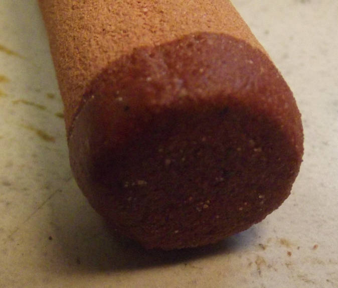
Electricity Generation
My (Old & New) Solar Power System(s)
My solar panels - New images, March 1st 2026
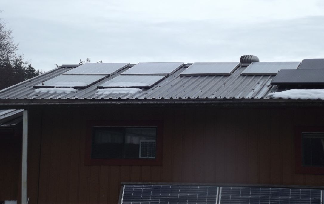 Panels for "House" off-grid system (10
KWH 36V battery) include six on the house roof
Panels for "House" off-grid system (10
KWH 36V battery) include six on the house roof
- my four old ~250 watt panels from 2011 and two 305 watt ones
from 2018...
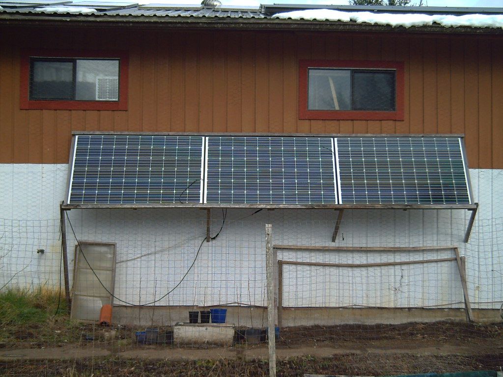
plus three 305 watt panels on the wall below them from 2018
or 2019
(They sat propped up on the lawn for several years)...
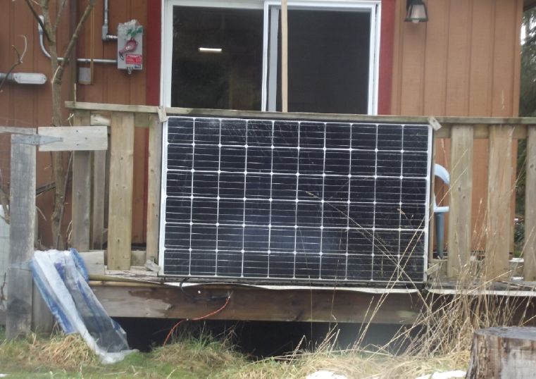
...and one 305W that the glass broke. (Powerful wind blew the
poorly anchored stand over.)
I didn't want to "install" it on a roof again, but it still
worked and there was a wire already run to near
the charge controller (originally for a windplant), so I
attached it to the porch rail and hooked it up.
I don't know if it puts out full power, the cable is long and
thin, and the location gets a lot of shade.
But it does more than nothing... or at least did when I last
checked it.
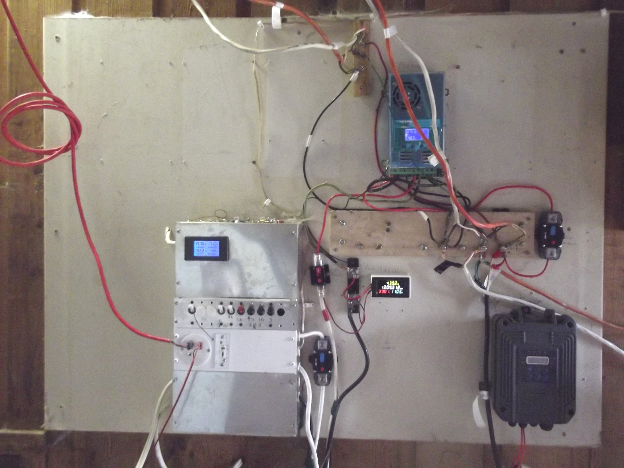
House solar power board (in garage)
No more "unapproved" grid ties - system is "off grid"
Box on right is control for solar well water pump
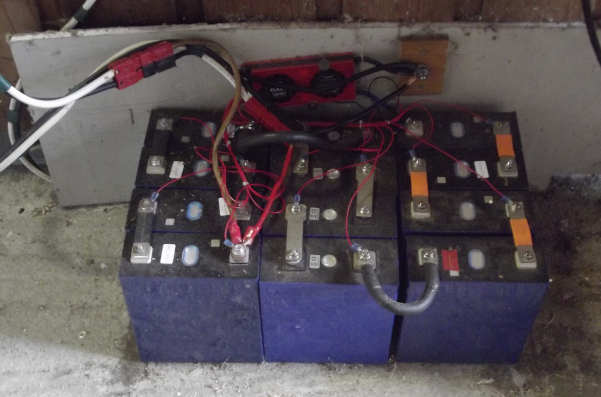
36V, 285 AH (~10 KWH) LiFePO4 battery below power board - cover
removed.
Balance charger (red) connects to each cell and must be mounted
with the battery.
(It is a problem with lithium types that they don't
self-balance.)
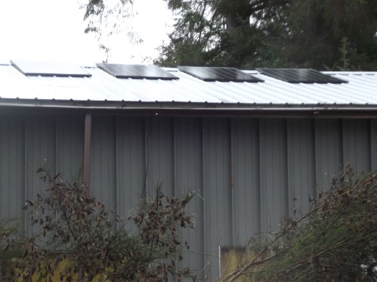
The cabin off grid system, which will soon have 20 KWH, 36 V, of
LiFePO4 battery
instead of 10 KW, has four 305 watt panels on the cabin roof...
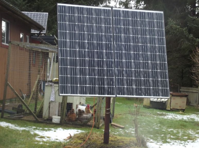
and a long wire from the house that connects
These two 305 watt panels on a pole, which gets a lot of
shade...
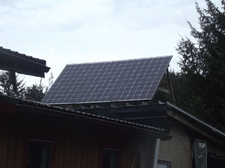
and three 305 watt panels on the carport roof, which gets the
least
amount of winter shadows of anywhere on the whole acreage.
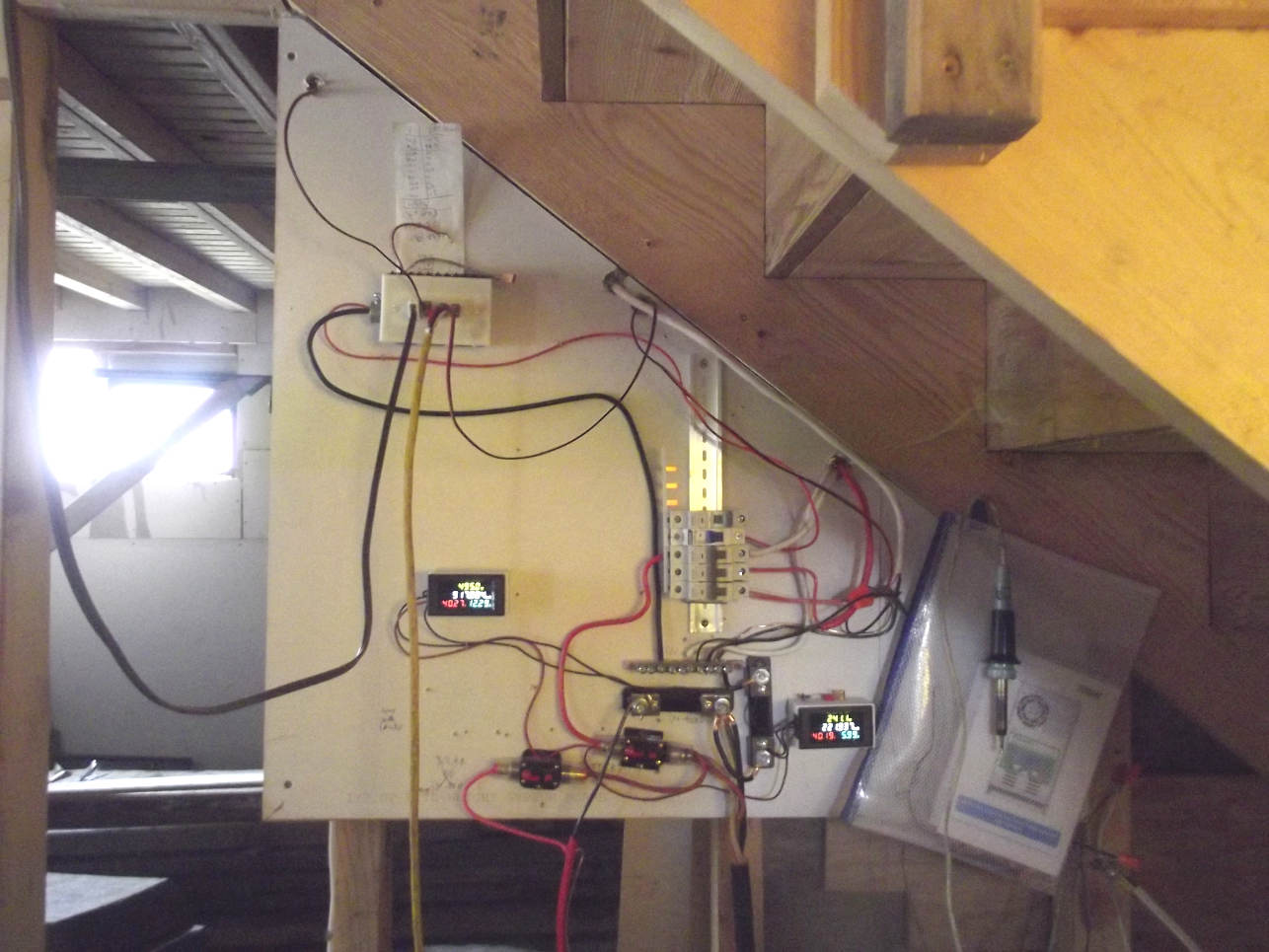
Cabin solar power board under stairs.
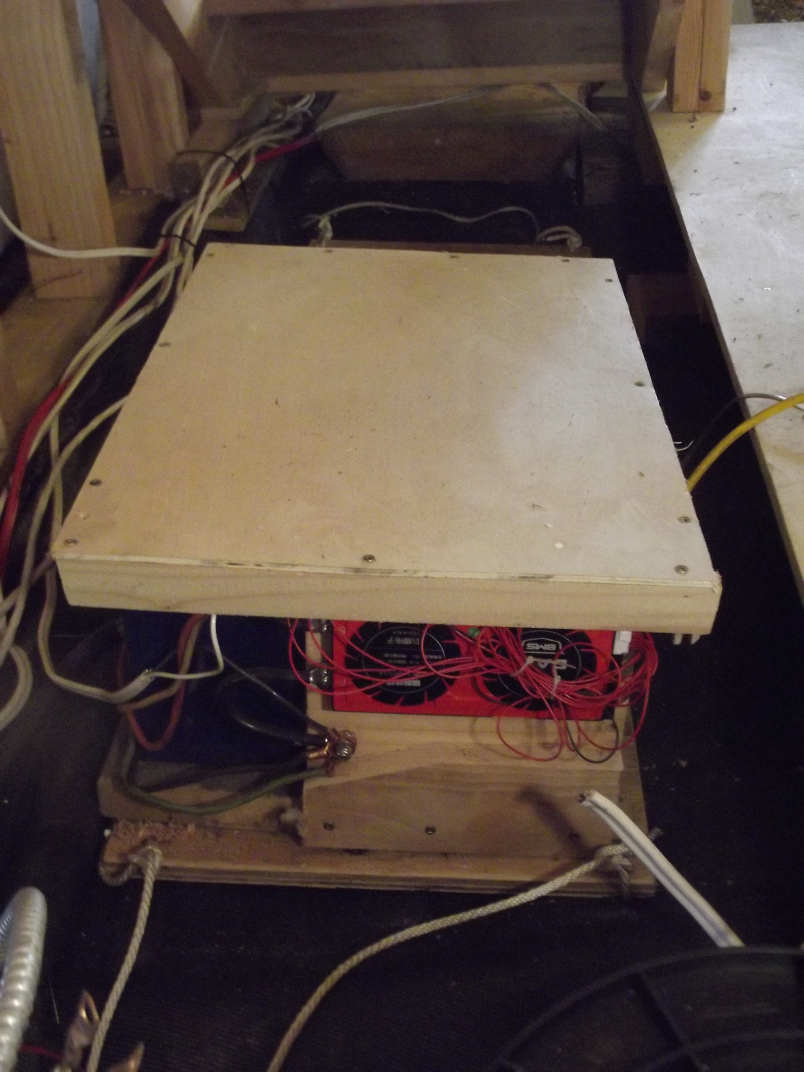
Cabin battery, again 36V, 10 KWH
Under stairs by power board.
(I'm about to add another set to make it ~22 KWH.)
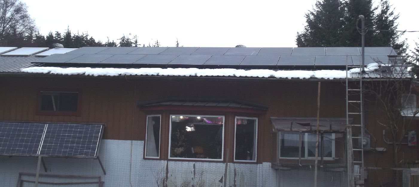
Finally, the grid tied system is rated 7 KW with twenty 350 watt
panels from 2025.
There's not much to see but the panels (and the outdoor shutoff
switch, extreme right) as the grid ties are beneath them.
These are not more efficient than the 305 watt ones from 2018 -
they're just proportionately larger.
(The other two systems together total 19 panels: House ~2830 W;
Cabin 2745 W; total ~5575 W.)
(Yes, heavy, wet snow has damaged the gutter and the window
greenhouse roof.)
Additional Solar Rebate
BC Hydro wrote me again after I had my 5000 $ rebate
cheque, asking for all my receipts with "Paid" written on them.
The reason? I am after all, being on a diesel powered "micro
grid", eligible for the credit I was told was available at the
renewable energy symposium: 75% of costs, maximum 20,000 $. It
wasn't on the rebate application or hinted at anywhere except when
I was told about it verbally.
It makes sense for BC Hydro to offer that much
because it costs them (IIRC) about 62¢/KWH for diesel fuel while,
in order to have a uniform price throughout the province, they
charge us 12¢. So we are heavily subsidized and it's BC Hydro that
saves most of the money when rooftop solar is installed.
I guess they didn't want the vast majority of
ineligible people all over the province inquiring about it or
trying to claim it - or complain that it was "unfair". But I
wonder how many eligible people looked and saw only the 5000 $
maximum and decided not to start a solar project. I myself had
started telling people the reputed 75% was only for native band
community projects, which is another 75% "micro grids" category.
The Usual Daily/Monthly/Yearly Log of Solar Power Generated
[and grid power consumed]
Notes:
* All times are in PST: clock ~48 minutes ahead of local
sun time, never PDT which is an hour and 48 minutes ahead.
* Unapproved AC/Grid Tied systems have been removed.
* House panels include four old ones on the roof (upper - total
rating ~ 1000W), two 305W on the roof, three 305W on the south
wall below the roof, and one broken panel mounted verticly on the
porch railing (seems to still work but a lot of shade there).
* Cabin DC includes the three carport panels and the two on a pole
in the yard as well as the four on the cabin roof itself. All nine
are 305W.
* The wall, pole and porch panels are easily wiped off from the
ground if it snows.
* Km = Nissan Leaf electric car drove distance, then car was
charged. Car KWH does not add to or subtract from any other
readings.
House System Panels: House roof, wall (9 solar panels) -
Porch (1 broken one - usually shady)
Cabin System Panels: Carport (3 - sunniest place on the
whole property) - Pole (2 - shadiest place) -Faraday Cabin (4 -
badly shaded in winter)
Date HouseDC,CabinDC,ACtoGrid =>
Total KWH Solar [grid use; etc.] New daily order as of December
6th 2025.
January
31st (est) 8.48, 8.88, 20.63 => 37.98 (6 days out of 8) [230
KWH grid] Dang, bad day to forget to take readings, Feb. 1st too!
February
2d 1149.32, 854.28, 162.27 => 12.66 (2 days of 8)
50.64 (8 days) [36587@23:30]
3rd 1149.82, 855.00, 163.24 => 1.69
[36633@23:30]
4th 1150.71, 856.09, 165.60 => 4.34
[36656@'24:00']
5th 1152.15, 857.50, 169.13 => 6.37
[36683@'24:00']
-- 5 days --> 10.37 KWH/day
10th 1159.15, 868.08, 203.40 => 51.85 [36871@18:00] Some sunny
days!
-- 4 days --> 15.29 KWH/Day
14th 1171.10, 878.80, 241.90 => 61.17 [37001@22:30]
15th 1174.38, 882.00, 253.24 => 17.82 [37037@23:30]
16th 1177.16, 884.61, 260.01 => 12.16 [37067@18:30]
-- 4 days --> 9.89 per day
20th 1189.33, 896.01, 296.01 => 39.57 [37254@'24:00']
-- 4 days --> 6.17 /day
24th 1194.81, 901.95, 309.28 => 24.69 [37454@19:30] Cloudy
days, on and on...
25th 1195.74, 903.97, 314.36 => 8.03 [37526@'24:00'] --
Yow, 72 KWH used! I left heat on in garage to dry out Miles truck,
which had been outside in the rain and weather.
26th 1197.55, 905.04, 317.29 => 5.81 [37556@19:30]
-- 2 days --> 10.02 /day
28th 1201.27, 909.38, 329.27 => 20.04 [37647@21:30]
March
1st 1203.30, 911.50, 345.61 => [37675@'24:30']
2d 1205.11, 913.30, 340.39 => [37724@22:30]
3rd 1208.40, 916.34, 351.05 => [37768@22:00]
Chart of daily KWH from solar panels. (Compare this
month with last month and with this month last year.)
Days of
__ KWH
|
February 2026
(38 solar panels)
|
January 2026
(the 18 old
collectors + 20 new)
|
February 2025
(18 C's - DC/
batteries only)
|
0.xx
|
|
1
|
|
1.xx
|
1
|
3
|
|
2.xx
|
|
1
|
|
3.xx
|
|
|
|
4.xx
|
1
|
1
|
|
5.xx
|
1
|
4
|
|
6.xx
|
7
|
6
|
|
7.xx
|
|
6
|
|
8.xx
|
1
|
|
|
9.xx
|
4
|
2
|
|
10.xx
|
7
|
1
|
|
11.xx
|
|
3
|
|
12.xx
|
1
|
3
|
|
13.xx
|
|
|
|
14.xx
|
|
|
|
15.xx
|
4
|
|
|
16.xx
|
|
|
|
17.xx
|
1
|
|
|
Total KWH
for month
|
313.54
|
226.17 |
|
Km Driven
on Electricity
|
743.5 Km
@7.4 Km/KWH
= 100
|
642.4 Km
@7.1 Km/KWH
= 90 KWH
|
|
Things Noted - February 2026
* March 1st marks SEVEN continuing years of solar electricity, on
or off grid.
* Driving Toyota Echo (gasoline) for longer trips in winter cold,
so less miles on Nissan Leaf (EV) lately.
* Days getting longer but only a few days with sunshine.
Monthly Summaries: Solar Generated KWH [& Power
used from grid KWH]
TABLES FOR SEVEN FULL YEARS
Monthly Summaries for SEVEN Years: Solar Generated KWH
[& Power used from grid KWH]
Month: House system (+ DC system at house) + Cabin system = KWH
made [used from grid]
2019
March 1-31: 116.19 + ------ + 105.93 = 222.12 KWH - solar [786
KWH used from grid] (10
solar panels total)
April - 1-30: 136.87 + ------ + 121.97 = 258.84 KWH [608 KWH]
May - 1-31: 156.23 + ------ + 147.47 = 303.70 KWH [543
KWH] (11th solar
panel connected on lawn on 26th)
June - 1-30: 146.63 + 15.65 + 115.26 = 277.54 KWH [374 KWH]
(36V, 250W Hot Water Heater installed on 7th)
July - 1-31: 134.06 + 19.06 + 120.86 = 273.98 KWH [342
KWH]
August 1-31:127.47 + 11.44+91.82+(8/10)*96.29 = 307.76 KWH [334
KWH] (12th solar
panel connected on lawn Aug. 1)
Sept.- 1-30: 110.72 + 15.30 + 84.91 = 210.93 KWH
[408 KWH] (solar includes 2/10 of 96.29)
Oct. - 1-31: 55.67 + 13.03 + 51.82 = 120.52 KWH
solar [635 KWH used from grid]
Nov. - 1-30: 36.51 + 6.31 + 26.29
= 69.11 KWH solar [653 KWH used from grid]
Dec. - 1-23: 18.98 + .84* + 11.70
= 31.52 KWH, solar + wind [711 KWH + 414 (while
away) = 1125 from grid]
2020
Jan. - 6-31: 17.52 + ------* + 10.61 = 28.13
KWH, solar+ wind [1111 KWH from grid]
Feb. - 1-29: 56.83 + ------* + 35.17 = 92.00
KWH, solar + wind [963 KWH from grid]
* The solar DC system was running the kitchen
hot water tank. Now it's only running a couple of lights - not
(usually) worth reporting. So there's just the 2 grid tie
systems: house and "roof over travel trailer" (AKA "Cabin").
One year of solar!
March - 1-31: 111.31 + 87.05 = 198.37 KWH solar
total [934 KWH from grid]
April - 1-30: 156.09 + 115.12 = 271.21 [784 KWH from
grid]
May - 1-31: 181.97 + 131.21 = 313.18 KWH Solar
[723 KWH from grid]
June - 1-30: 164.04 + 119.81 = 283.82 KWH Solar [455
KWH from grid]
July - 1-31: 190.13 + 110.05 = 300.18 KWH
Solar [340 KWH from grid]
August- 1-31: 121.81 + 83.62 = 205.43 KWH Solar
[385KWH from Grid]
Sept. - 1-30: 110.68 + 65.09 = 175.77 KWH
Solar [564 KWH used from grid]
Oct. - 1-31: 67.28 + 42.55 =
109.83 KWH Solar [1360 KWH from grid -- Renters!]
Nov. - 1-30: 35.70 + 20.79 =
56.49 KWH of Solar [1301 KWH from grid]
Dec. - 1-31: 19.78 + 11.31 =
31.09 KWH Solar [1078 KWH used from grid]
2021
Jan: 25.47 + 18.58 = 44.05 KWH Solar [1185 KWH
used from grid] (1
solar panel moved to DC system only -- 11 panels)
Feb: 47.18 + 33.22 = 80.40 KWH Solar [1121 KWH
used from grid]
Two years of solar!
Mar: 81.73 + 55.22 + 2.2 (DC) = 139.15 KWH
Solar [1039 KWH grid]
April: 161.83 + 112.35 + .44(DC) = 274.62 KWH Solar [680
KWH from grid]
May: 156.25 + 97.22 + 1.29(DC) = 254.76 KWH Solar
[678 KWH from grid]
June: 197.84 + 112.07 + 2.21(DC) = 312.12 KWH Solar [& 448
KWH from grid] (Connected
12th solar panel -- 13 panels total but one goes to DC
system only.)
July: 204.35 + 121.21 + 4.06(DC) = 329.62 KWH Solar [426
KWH from grid; 150(?) KWH used by Nissan Leaf]
Aug: 176.19 + 102.91 + 5.37(DC) = 284.47 KWH Solar [477
KWH from grid; 165 KWH (est) used by car]
Sept: 94.35 + 51.34 + 3.30(DC) = 152.29
KWH Solar [590 KWH from grid; 155 KWH (est) used by car]
Oct: 77.52 + 41.85 + 4.10(DC) =
123.47 KWH Solar [1066 KWH from grid; 150 KWH (est) used by car]
(2 new panels on
pole making 14 -- but they are mostly in shadows all
winter.)
Nov: 34.69 + 18.92 + 3.82 = 57.43 KWH Solar
[1474 KWH from grid (ouch!); 140 (est) used by car]
Dec: 24.00 + 5.22 + 3.76 = 32.98 [1589 KWH from grid
(ouch again! Must be the -10°'s); 120 KWH used by car] (New switches allow
switching some panels between AC and DC as needed, so all
15 panels are productively employed.)
2022
Jan: 32.83 + 20.54 + 4.57 = 57.94 KWH Solar [2556 from grid]
Double ouch! Trailer 400W heater, Perry's RV 500W heater,
bedroom heat, car using extra power (100 KWH with less
driving)... and so little sun!
Feb: 66.63 + 32.09 + 3.42(DC) = 102.14 KWH Solar [1118 KWH from
grid; 130 (est) used by car]
Three years of solar!
March:128.53 + 82.29 + 3.66(DC) = 214.48 [1124 KWH from grid;
160 KWH (est) used by car]
April: 251.29 + 149.87 + 3.01(DC) = 404.17 KWH Solar [911 KWH;
est. 170 KWH used by car]
May: 255.01(house)+6.46(DC)+140.46(carport)+145.91(cabin)=547.74
KWH Solar [933 KWH from grid; 140 KWH (est) used by car; Bitcoin
miner using extra power from 22nd on.] (3 new solar panels on
carport roof -- sunniest location around -- total 18
panels)
Jun: 234.54 + 2.10 + 160.70 + 139.18 = 536.52 KWH [from grid:
864 KWH - dang bitcoin miner!]
July: 232.12 + 4.57 + 143.03 + 139.65 = 519.37 KWH Solar [from
power grid: 710 KWH; 165 KWH (est) used by car]
Aug: 205.57 + 4.20 + 157.88 + 137.47 = 505.32 KWH Solar [from
grid: 561 KWH; 145 KWH (est) used by car]
Sept:165.52 + 3.97 + 132.24 + 104.29 = 406.02 KWH Solar [from
grid: 856 KWH; car used (est): 165 KWH]
Oct: 97.96 + 2.86 + 78.76 + 59.04 = 238.62 KWH Solar
[from grid: 1067 KWH; car used (est): 143 KWH]
Nov: 47.37 + 3.30 + 37.81 + 26.43 = 114.91 KWH solar.
[from grid: 1504 KWH; car used (est): 120 KWH]
Dec: 31.05 + 3.11 + 29.46 + 16.35 = 79.97 KWH Solar. [from
grid: 1266 KWH; car used (est): 135 KWH]
2023 - (House roof, lawn + DC + Cabin + Carport, Pole)
Solar
Jan KWH: 40.57 + 3.06 + 28.31 + 21.85 = 93.79 Solar [grid: 1163;
car (est): 130]
Feb KWH: 59.19 + 2.70 + 38.10 + 32.47 = 132.46 Solar [grid:
1079; car: 110]
Four years of solar!
Mar KWH: 149.49 + 2.72 +
53.85 + 92.08 = 298.14 Solar [grid: 981; car:
140]
Apr KWH: 176.57 + 2.71 + 121.21 + 108.34 = 408.83 [grid: 676;
car: 160]
"Lawn" collectors
moved to South "Wall"
May KWH:266.04 + 2.04 + 194.13 + 180.31 = 642.52 [grid: 500;
car: 175]
Jun KWH: 237.55 + 3.70 + 172.56 + 126.31 = 540.12 [grid: 464;
car: 190]
July KWH:236.99 + 1.95 + 169.16 + 155.21 = 563.31 [grid: 343;
car: 180]
Aug KWH:223.61 + 1.78 + 158.31 + 134.40 = 518.00 [grid: 305;
car: 130]
Sep KWH:124.33 + 2.33 + 92.76 + 76.23 = 295.65
[grid: 501; car: 150]
Oct KWH: 94.26 + 2.70 + 55.01 +
56.11 = 208.08 [grid: 842; car: 170]
Nov KWH: 45.70 + 3.10 + 24.35 + 15.91
= 89.06 [grid: 760; car: 120]
Dec KWH: 28.96 + 2.43 + 15.58 + 10.96
= 57.93 [grid: 815; car: 110]
2024
Month: HouseAC +
DC +Carport+Cabin[+DC] (from Aug 2024)
Jan KWH: 31.37 + 3.14 + 16.85 + 16.82 =
68.18 [grid power used: 909; car (very rough estimates): 160*]
Feb KWH: 96.52 + 2.36 + 49.67 + 52.98 = 201.53 [grid:
791; car: 130]
FIVE full
Years of solar!
Mar KWH 150.09+ 1.63 + 93.59 + 92.50 = 337.81
[grid: 717; car: 140]
Apr KWH 181.89+35.55 +123.50+142.74 = 483.68
[grid: 575; car: 140]
May KWH 129.23+67.38 +109.6 +126.32 = 432.53
[grid: 405; car: 145]
Jun KWH 152.54+51.02+118.99+141.17 = 463.72
[grid: 420; car: 190]
July KWH 174.22+30.53+111.19+128.62 = 444.56
[grid: 386; car:
165]
Aug KWH 221.99+ 2.63 +142.49+151.67+ 5.78 = 524.56
[grid: 358; car: 180]
SeptKWH 120.98+ 2.49 + 83.50 + 19.10+ 39.95 = 266.02 [grid:
662 (yowr!); car: 155*]
Oct KWH 78.48+ 7.29 + 64.39 + 7.52 + 40.75 =
198.43 [grid: 711; car: 120*]
Nov KWH 19.63+12.19+ 23.90 + 3.35 + 25.62
= 84.69 [grid: 900 (ACK!);car: 110*]
Now solar is
charging batteries only. 2 DC systems: house, cabin.
Dec KWH 20.37 + 16.76 = 37.13 [grid: 1866 (using
electric heat!); car: 120*]
2025
Jan KWH 35.02 + 26.30 = 61.32 [grid: 2136 (electric
heat OW!); car: 120*]
Feb KWH 55.43 + 39.00 = 94.43 [grid: 1937; car: 100*]
SIX full
Years of solar! (now 18 solar panels in two off-grid systems)
Mar KWH 115.13 + 87.41 = 202.54
[grid: 1860; car: 155* KWH]
Apr KWH 126.25 + 120.36 = 246.61 [grid: 1246; car: 100*]
May KWH 147.08 + 186.24 = 333.32 [grid: 1354; car: 150*]
Jun 145.58 + 170.97 = 316.55 [grid: 959; car: 130*]
July 156.48+ 86.78 = 243.26 [grid: 653; car 130]
Aug 118.56 + 48.50 = 167.06 [grid: 616; car 150]
Sept 115.15+ 63.87 = 179.02 [grid: 576; car: trip meter reading
lost with 12V battery replacement]
Oct 93.22 + 40.86 = 134.08 [grid: 868; car: 50]
Nov 45.62 + 37.84 = 83.46 [1088; car: 125]
New 20 solar panel, 7 KW grid
tied system activated
Dec 26.88 + 29.89 + 36.62 = 93.39 [1320; car: 100]
2026
Jan 51.11 + 56.28 + 118.78 = 226.17 [grid: 1288; car:
90*]
Feb 58.22 + 61.66 + 193.66 = 313.54 [1157; 100]
Seven
full Years of solar! (now 38 solar panels total in three
separate systems)
* Note: Car consumption comes from solar and or grid: it
does not add to other figures. (Just from grid from Nov. 18th.
2024 except some direct solar charging summer 2025)
Annual Totals
1. March 2019-Feb. 2020: 2196.15 KWH Solar [used 7927
KWH from grid; EV use: -] 10, 11, 12 solar panels
2. March 2020-Feb. 2021: 2069.82 KWH Solar [used 11294 KWH from
grid; EV use: - (More electric heat - BR, Trailer & Perry's
RV)] 12 solar panels
3. March 2021-Feb. 2022: 2063.05 KWH Solar [used 10977 KWH from
grid; EV use ~~1485 KWH] 12 solar panels, 14 near end of year.
4a. March 2022-August 2022: in (the best) 6 months, about 2725 KWH
solar - more than in any previous entire year!
4. March2022-Feb. 2023: 3793.37 KWH Solar [used 12038 KWH from
grid; EV use: ~1583 KWH] 14, 15, 18 solar panels
5. March 2023-Feb. 2024: 3891.35 KWH Solar [used 7914 KWH from
power grid; EV use: ~1515 KWH] 18 solar panels
6. March 2024-Feb. 2025: 3428.88 KWH Solar [used 12773 KWH from
grid; EV used: ~1685 KWH]
7. March 2025-Feb. 2026:
Money Saved or Earned - @ 12¢ [All BC residential elec.
rate] ; @ 50¢ [2018 cost of diesel fuel to BC Hydro] ; @ 1$ per
KWH [actual total cost to BC Hydro in 2022 according to an
employee]; or maybe it's 62 ¢/KWH [according to BC Hydro at
Renewable Energy Symposium Sept. 2024]:
1. 263.42$ ; 1097.58$ ; 2196.15$
2. 248.38$ ; 1034.91$ ; 2069.82$
3. 247.57$ ; 1031.53$ ; 2063.05$
4. 455.20$ ; 1896.69$ ; 3793.37$
5. 466.96$ ; 1945.68$ ; 3891.35$
6. 411.47$ ; 1714.44$ ; 3428.88$
I had to disconnect the system from the grid in
November 2024. These two now independent installations (house,
cabin) will continue to run their 36 volt DC systems and I'll see
how I can most effectively utilize the available solar energy with
the limited available storage.
http://www.TurquoiseEnergy.com
Haida Gwaii, BC Canada