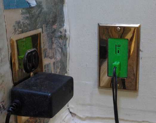
12 VDC outlet by the "solar fridge", nearby a 120 VAC outlet
(Ironically, the AC outlet has a 12 VDC power adapter plugged in for the LED globe light that lit the corner for the foto!)
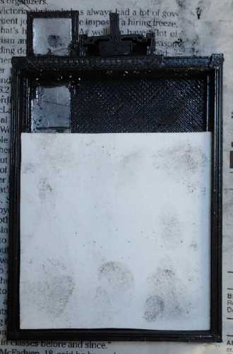
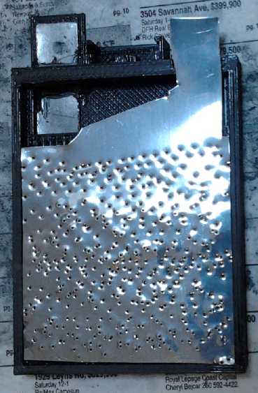
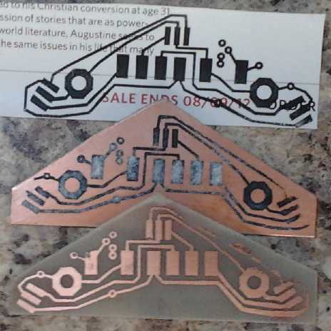 I'd also
read some people used glossy magazine paper instead of
acetate. One web site finally explained why: you can soak the paper
off, so it
won't lift any of the toner from the copper board. Aha! Finally I saw
the
glimmer of potential good results! (And here I
thought people were just using
it because they were being cheap!)
Trying it
revealed more details: thin magazine paper transfers the heat to the
toner and board better, and there seems to be less smear. On the minus
side, you can't see through it to see any spots of toner that haven't
transferred.
I'd also
read some people used glossy magazine paper instead of
acetate. One web site finally explained why: you can soak the paper
off, so it
won't lift any of the toner from the copper board. Aha! Finally I saw
the
glimmer of potential good results! (And here I
thought people were just using
it because they were being cheap!)
Trying it
revealed more details: thin magazine paper transfers the heat to the
toner and board better, and there seems to be less smear. On the minus
side, you can't see through it to see any spots of toner that haven't
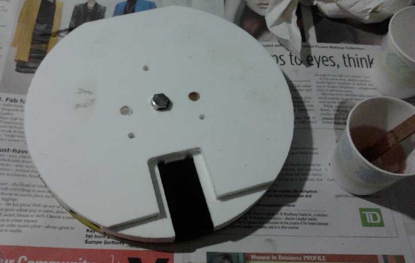
transferred.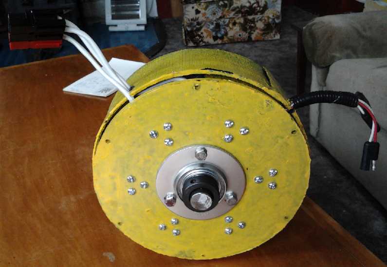 * I fitted the pressed
shell
bearings to the motor bells on
the 5th, using hex bolts and "T" nuts since the intended carriage bolt
system was too bulky to fit in at either end. Theoretically the motor
could be thinner and slightly smaller diameter, but in practical terms
it was as thin and small as I could make it and I almost made the rotor
compartment too thin to fit everything. On the rotor bushing I had to
drill recesses and use flat
head bolts to eliminate the normally protruding hex heads.
* I fitted the pressed
shell
bearings to the motor bells on
the 5th, using hex bolts and "T" nuts since the intended carriage bolt
system was too bulky to fit in at either end. Theoretically the motor
could be thinner and slightly smaller diameter, but in practical terms
it was as thin and small as I could make it and I almost made the rotor
compartment too thin to fit everything. On the rotor bushing I had to
drill recesses and use flat
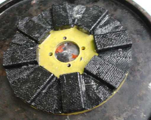
head bolts to eliminate the normally protruding hex heads.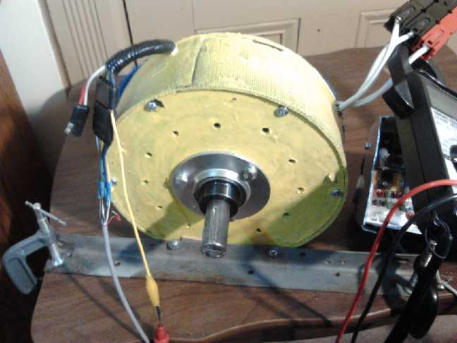 After
completing the second magnet installation, I tried the motor again and
ran a few tests. It ran great, smooth and well balanced. I got nervous
about turning the RPM up too high and chickened out at 2700 RPM - and
at only about 1/4 or 1/3 "throttle". My instinct said it'd be safer to
call it a 2000 or at most 2500 RPM motor instead of the planned 3000. I
also thought it was using too many watts to turn with no load, but the
power needed went down considerably as (presumably) the bearings warmed
up. I was then in essence happy with the motor, barring a few ideas for
improvements that could wait for another occasion or the next motor.
(One idea in particular is to add a microcontroller control to
limit such motors to safe RPMs
- but that's the domain of the motor controller rather than the
motor.)
After
completing the second magnet installation, I tried the motor again and
ran a few tests. It ran great, smooth and well balanced. I got nervous
about turning the RPM up too high and chickened out at 2700 RPM - and
at only about 1/4 or 1/3 "throttle". My instinct said it'd be safer to
call it a 2000 or at most 2500 RPM motor instead of the planned 3000. I
also thought it was using too many watts to turn with no load, but the
power needed went down considerably as (presumably) the bearings warmed
up. I was then in essence happy with the motor, barring a few ideas for
improvements that could wait for another occasion or the next motor.
(One idea in particular is to add a microcontroller control to
limit such motors to safe RPMs
- but that's the domain of the motor controller rather than the
motor.)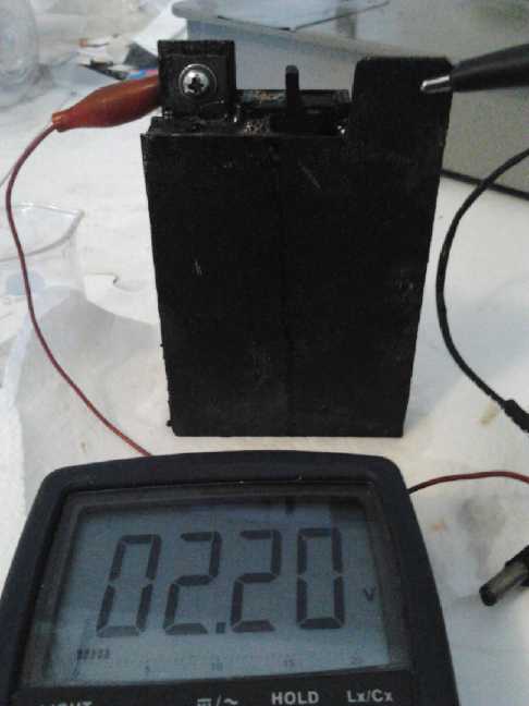 All the test
battery cells I've made able to open for
trying various things and inspection have leaked and become encrusted
in salt from the electrolyte around the seams. The leaks cause
self-discharge and loss of
electrolyte, making any longer period test results questionable at
best. On the 20th I decided that, having a proven
chemistry, workable materials, and now a plan in my head for what ought
to be good, working cells, it was time to put together a production
battery design that would be securely glued shut, and a much faster
means for producing electrodes - as simple, highly compacted briquettes.
All the test
battery cells I've made able to open for
trying various things and inspection have leaked and become encrusted
in salt from the electrolyte around the seams. The leaks cause
self-discharge and loss of
electrolyte, making any longer period test results questionable at
best. On the 20th I decided that, having a proven
chemistry, workable materials, and now a plan in my head for what ought
to be good, working cells, it was time to put together a production
battery design that would be securely glued shut, and a much faster
means for producing electrodes - as simple, highly compacted briquettes.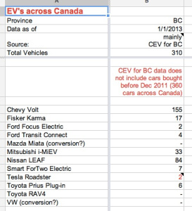
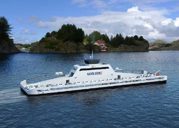 Also of interest, the first ever 120 car, 360
passenger, 80 meter catamaran
electric ferry is said to be going into operation in Norway in 2015.
(So far, it looks like it's a computer graphic judging by all the
identical cars.) All the
subheadings here
this month are about the "Mini Electric Hubcap Motor", now
titled the Electric Caik Motor ("ElectricCake.com" was taken).
It continues - and essentially concludes - the motor development story
started in December, including the
making of the molds and jigs to produce the motors, and the making and
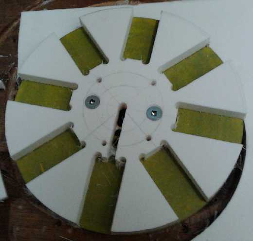
initial testing of the first one, which runs great. It runs great,
and the rotor is the best balanced one I've
made, thanks to the new magnet placement jig below. I had thought that
if the regular Electric Hubcap was 0 to 2000 RPM with a 10" magnet
rotor, the new one should be about 0 to 3000 RPM with a 7.5" rotor, but
as I increased the speed, despite running smoothly the energy seemed so
ominous that I stopped at 2700 RPM and headed down again, and decided
that maybe it should be rated 0 to 2000 RPM as well, or not a lot more.
The back EMF (Kv) seemed quite low at 5.1 mV/RPM and it attained those
RPMs with quite low control settings. This would be partly because I
used thinner supermagnets, .375" instead of .5", in spite of the fact
that the flux gap is probably down to 10 or 11 mm instead of 14 to 16.
I think that if I turned it right up with the 24 volt supply and no
load, the motor speed would increase until it self destructed, even if
that didn't happen until 5000 or more RPM. I'm starting to think that a
microcontroller overseeing operation is really a necessity if only to
set an RPM limit at a
safe maximum regardless of flux gap and load.
Also of interest, the first ever 120 car, 360
passenger, 80 meter catamaran
electric ferry is said to be going into operation in Norway in 2015.
(So far, it looks like it's a computer graphic judging by all the
identical cars.) All the
subheadings here
this month are about the "Mini Electric Hubcap Motor", now
titled the Electric Caik Motor ("ElectricCake.com" was taken).
It continues - and essentially concludes - the motor development story
started in December, including the
making of the molds and jigs to produce the motors, and the making and
initial testing of the first one, which runs great. It runs great,
and the rotor is the best balanced one I've
made, thanks to the new magnet placement jig below. I had thought that
if the regular Electric Hubcap was 0 to 2000 RPM with a 10" magnet
rotor, the new one should be about 0 to 3000 RPM with a 7.5" rotor, but
as I increased the speed, despite running smoothly the energy seemed so
ominous that I stopped at 2700 RPM and headed down again, and decided
that maybe it should be rated 0 to 2000 RPM as well, or not a lot more.
The back EMF (Kv) seemed quite low at 5.1 mV/RPM and it attained those
RPMs with quite low control settings. This would be partly because I
used thinner supermagnets, .375" instead of .5", in spite of the fact
that the flux gap is probably down to 10 or 11 mm instead of 14 to 16.
I think that if I turned it right up with the 24 volt supply and no
load, the motor speed would increase until it self destructed, even if
that didn't happen until 5000 or more RPM. I'm starting to think that a
microcontroller overseeing operation is really a necessity if only to
set an RPM limit at a
safe maximum regardless of flux gap and load.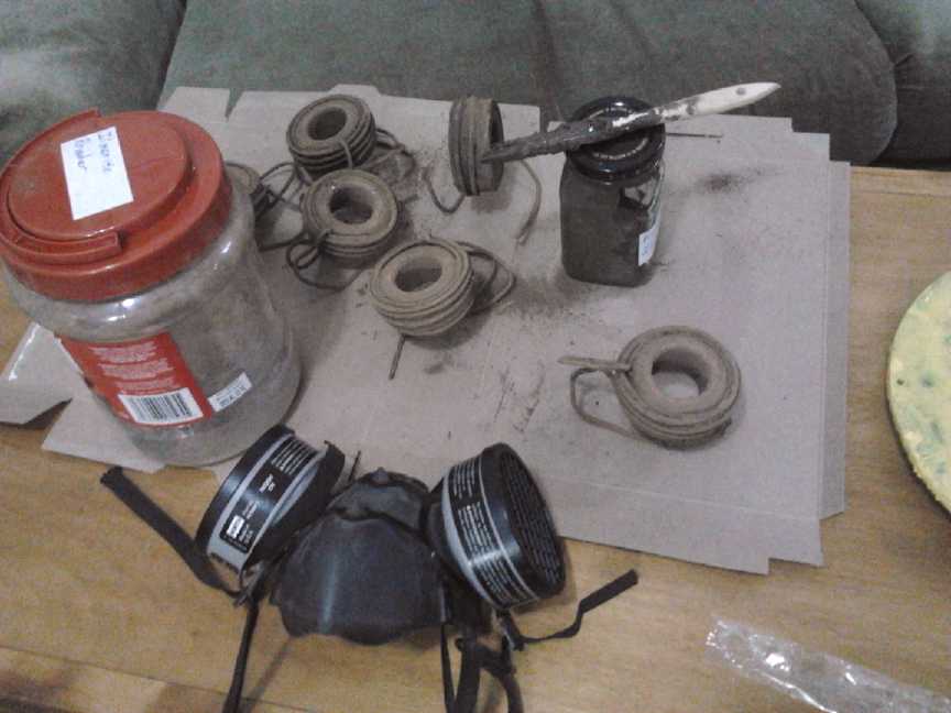
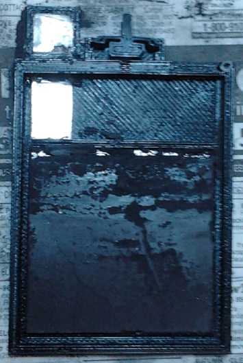
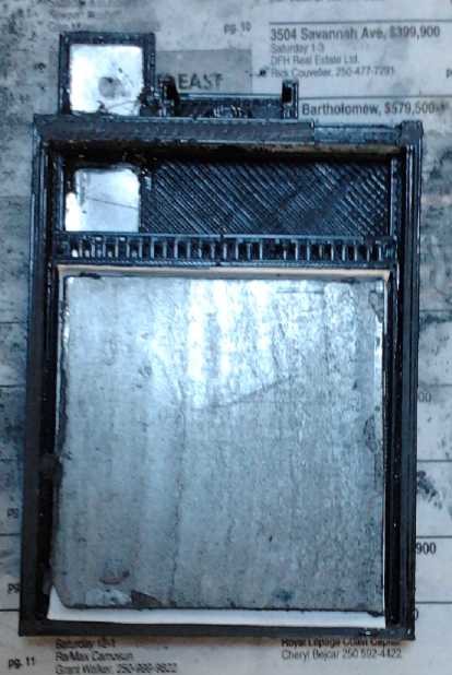
 Sometime I
heard that iron-on transfers printed on a laser
printer
worked better if the sheet was repeatedly printed with the same
pattern, thickening the toner on the acetate sheet. Although not
optimistic about the probable results, I decided to give this a try,
with the LED constant current board I designed last summer.
Sometime I
heard that iron-on transfers printed on a laser
printer
worked better if the sheet was repeatedly printed with the same
pattern, thickening the toner on the acetate sheet. Although not
optimistic about the probable results, I decided to give this a try,
with the LED constant current board I designed last summer.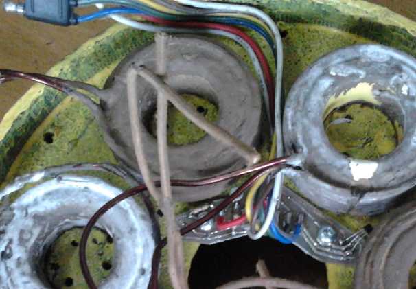
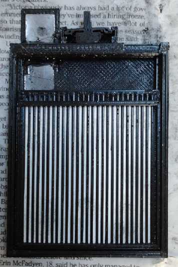
 I had planned
to test the magnet sensor board before
bolting the
stator together. On the 19th, I was ready to close it up. First I
tested the board and was glad I did: a solder
blob across two traces kept one of the sensors from working (and
seemingly blew it), and like the previous motor, the temperature sensor
didn't work. The previous motor was also the first time it had occurred
to me to try reading the temperature, since I haven't run any of the
motors long enough to get very warm since designing the PC board with
the
temperature as well as the hall sensors. Investigation disclosed that
the AD590
temperature sensor part in the Eagle PCB components 'library' was
defined mirror image. (I probably defined it myself.) Turning it around
fixed it, and I'll redo the PCB design for next time.
I had planned
to test the magnet sensor board before
bolting the
stator together. On the 19th, I was ready to close it up. First I
tested the board and was glad I did: a solder
blob across two traces kept one of the sensors from working (and
seemingly blew it), and like the previous motor, the temperature sensor
didn't work. The previous motor was also the first time it had occurred
to me to try reading the temperature, since I haven't run any of the
motors long enough to get very warm since designing the PC board with
the
temperature as well as the hall sensors. Investigation disclosed that
the AD590
temperature sensor part in the Eagle PCB components 'library' was
defined mirror image. (I probably defined it myself.) Turning it around
fixed it, and I'll redo the PCB design for next time.
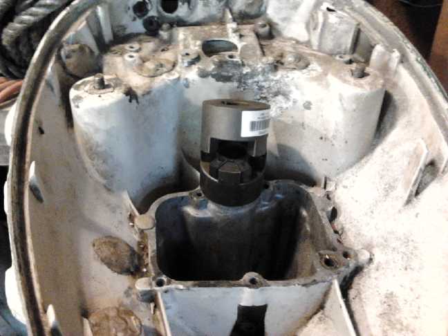 I took
a piece of 1/2" square steel rod and stuck it into
the splined socket of the leg drive shaft in the Honda. To my surprise
it was virtually a perfect fit. I took a Joy coupling I had lying
around and realized that if I rounded the corners a bit, the square
steel would fit it perfectly. So, one 2-1/2" piece of steel and a bit
of grinding and filing later, I had a fitting in the outboard. On the
24th I bought the rubber center piece and the Joy coupling to fit the
motor
shaft, and it's done. (Amazing how a shopping trip can eat up a whole
morning or afternoon.)
I took
a piece of 1/2" square steel rod and stuck it into
the splined socket of the leg drive shaft in the Honda. To my surprise
it was virtually a perfect fit. I took a Joy coupling I had lying
around and realized that if I rounded the corners a bit, the square
steel would fit it perfectly. So, one 2-1/2" piece of steel and a bit
of grinding and filing later, I had a fitting in the outboard. On the
24th I bought the rubber center piece and the Joy coupling to fit the
motor
shaft, and it's done. (Amazing how a shopping trip can eat up a whole
morning or afternoon.)
 The new cell,
supposedly Mn-Fe, would charge up to well over 2 volts, the voltage for
Mn-Mn, instead of maybe 1.6 or so. I consider that the posode initially
loses a little unchelated KMnO4 into the electrolyte. The MnO4- ion
finds its
way to the negode and discharges to
MnO2->Mn2O3->Mn3O4->Mn(OH)2->Mn (all solid, the last
metallic), coating the negode with Mn as a higher voltage surface
charge.
The new cell,
supposedly Mn-Fe, would charge up to well over 2 volts, the voltage for
Mn-Mn, instead of maybe 1.6 or so. I consider that the posode initially
loses a little unchelated KMnO4 into the electrolyte. The MnO4- ion
finds its
way to the negode and discharges to
MnO2->Mn2O3->Mn3O4->Mn(OH)2->Mn (all solid, the last
metallic), coating the negode with Mn as a higher voltage surface
charge.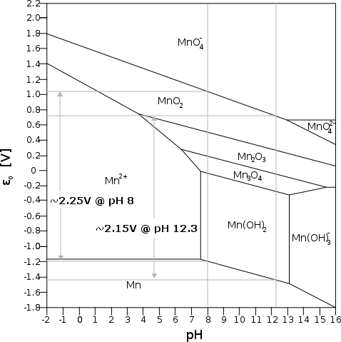 I've sung the
praises of manganese as a battery ingredient
for both electrodes before, but here's another perspective. A great
beauty of manganese is that in every state of
oxidation from Mn metal to MnO4- (valence 7), it has electrical
conductivity. It can electrically charge or discharge all the way from
one end to the other; it can't be passivated, which is the chief factor
limiting the life of most batteries. All the states except permanganate
are also insoluble.
I've sung the
praises of manganese as a battery ingredient
for both electrodes before, but here's another perspective. A great
beauty of manganese is that in every state of
oxidation from Mn metal to MnO4- (valence 7), it has electrical
conductivity. It can electrically charge or discharge all the way from
one end to the other; it can't be passivated, which is the chief factor
limiting the life of most batteries. All the states except permanganate
are also insoluble.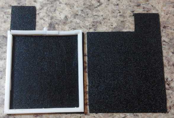 On the 20th,
since I thought I pretty much knew in almost
every detail what I wanted to do to make production MnMn flooded cells
(along the lines of last month's writing), I decided it was time to
bite the bullet, make all the needed tools to make them and design the
3D plastic pieces, and try making some. This seems something of a
gamble, but with yet another test
cell oozing salt out the seams and discharging itself, it seems making
test cells has been something of a losing proposition and isn't
providing any more especially useful results.
On the 20th,
since I thought I pretty much knew in almost
every detail what I wanted to do to make production MnMn flooded cells
(along the lines of last month's writing), I decided it was time to
bite the bullet, make all the needed tools to make them and design the
3D plastic pieces, and try making some. This seems something of a
gamble, but with yet another test
cell oozing salt out the seams and discharging itself, it seems making
test cells has been something of a losing proposition and isn't
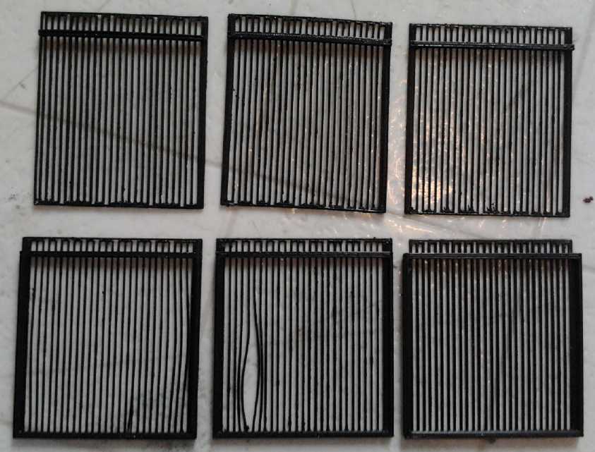
providing any more especially useful results.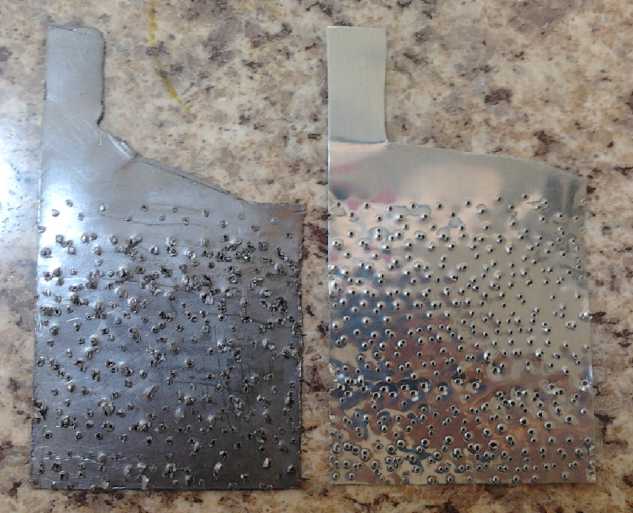 It seemed to me that rough material would contact the
briquettes far batter than the smooth sheets of flexible graphite and
zinc. But what rough material? I've never seen a zinc mesh or grill. I
dislike working with carbon (graphite) fiber, but perhaps that would be
an option to make a "grill" for the positrode? Of course, there would
be no way to electrically bind it to the current collector except by
random contact.. or perhaps by winding it around the whole sheet.
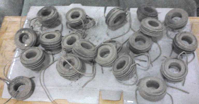
It seemed to me that rough material would contact the
briquettes far batter than the smooth sheets of flexible graphite and
zinc. But what rough material? I've never seen a zinc mesh or grill. I
dislike working with carbon (graphite) fiber, but perhaps that would be
an option to make a "grill" for the positrode? Of course, there would
be no way to electrically bind it to the current collector except by
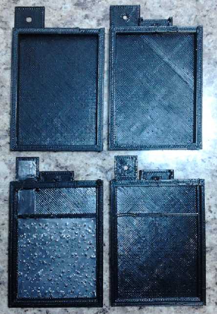
random contact.. or perhaps by winding it around the whole sheet.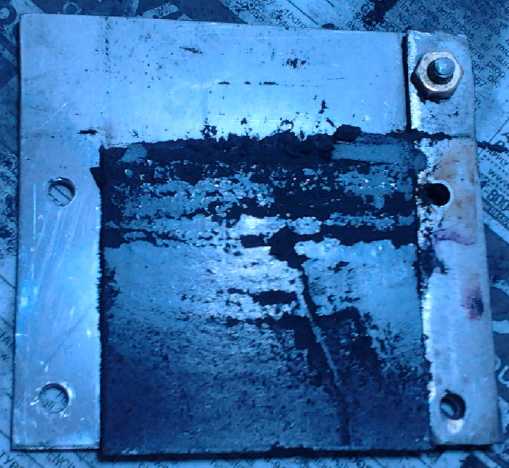 On the evening
of the 29th I made a positrode. I used about
the same permanganate-nickel-graphite mix as last time, with a bit more
graphite added to it. I removed the top plate from the book press to
get more pressing height, making a very nice screw press except that
the screw had no
non-turning end piece on it. But it was good enough and the compactor
seemed to compact very well. I added more and more of the powder until
20 grams had been consumed. (From which one might estimate 5 to 8
amp-hours capacity if utilization is good.) Even then it wasn't quite
full size. Because I had made one side of the compactor exactly the
63mm electrode
height, it was hard to add powder to get it right to the top without it
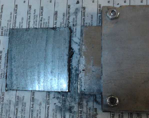
spilling. If I pressed it
hard enough, the 2.6mm stainless steel bulged. (.1" was the thickest
piece of flat stainless steel the recycling place had at the time.)
On the evening
of the 29th I made a positrode. I used about
the same permanganate-nickel-graphite mix as last time, with a bit more
graphite added to it. I removed the top plate from the book press to
get more pressing height, making a very nice screw press except that
the screw had no
non-turning end piece on it. But it was good enough and the compactor
seemed to compact very well. I added more and more of the powder until
20 grams had been consumed. (From which one might estimate 5 to 8
amp-hours capacity if utilization is good.) Even then it wasn't quite
full size. Because I had made one side of the compactor exactly the
63mm electrode
height, it was hard to add powder to get it right to the top without it
spilling. If I pressed it
hard enough, the 2.6mm stainless steel bulged. (.1" was the thickest
piece of flat stainless steel the recycling place had at the time.)