Turquoise
Energy Ltd. News #61
Victoria BC
Copyright 2013 Craig Carmichael - March 5th, 2013
www.TurquoiseEnergy.com
= www.ElectricCaik.com
= www.ElectricHubcap.com
= www.ElectricWeel.com = www.MushroomOutboard.com
Features:
* Woodstove Thermoelectric
Generator: 60-150W of free electric power from heat
* Electric Caik Outboard Motor test on the water: Great performance
& efficiency! Quiet!
* Peltier Heat Pump for House & EV Heating: 200% COP (~400W heat
for
200W electricity!)
Month In Brief
(Project Summaries)
- modified newsletter format - MnMn batteries: improving, and just 5
cells makes 12 volts!
- Electric Caik Outboard Motor on the water - woodstove thermoelectric
generator - Efficient thermoelectric heat pumping & refrigeration!
- magnetic heat pumping
crossed off the
project list.
In Passing (Miscellaneous
topics, editorial comments & opinionated rants)
- Bursting Bubbles - Upside down economy
Electric Transport - Electric Hubcap Motor
Systems
* Electric Caik Motor [Honda 7.5] Outboard motor.
- Boat Launch & tests!
* Centrifugal clutch for car PGTC transmission system (why didn't I
think of
it sooner?)
Other "Green" Electric Equipment Projects
* need for an all-inclusive hub to tie in various energy sources,
storage
devices, and loads.
* New design of Peltier module heat pumps for space heating: 200%
coefficient of
performance!
- evolving designs & COP measurement experiments
- Peltier fridges: same design principle cuts power consumption
in half!
Electricity Generating
* Woodstove Thermoelectric Generator (TEG) -
Perfect complement to solar panels!
- Picking the right TEGs
- Heat transfer with water
- Evacuated heat transfer tubes: thousands of times faster heat
transfer than copper or aluminum!
- Pressurized pipe to remove woodstove heat only if temperature
hits TEG max rating of 190ºC.
- Better Peltier fridges and Peltier heat pumps with evacuated
pipes?
* Low temperature steam turbine with evacuated pipes?
* River/stream Hydro power with surface water wheels.
Electricity Storage - Turquoise
Battery Project etc.
* Production Prototype Mn-Mn Cell #2: not great, but continues working
without leaks or deterioration.
- updated cell assembly instructions
* NiMH cells - safety issues - causes of troubles in January and
Februaury.
No Project Reports on: DSSC
solar cells, LED Lighting, Pulsejet steel
plate cutter, Magnetic
Motion Machine, Large
format NiMH batteries - take 3, CNC Gardening/Farming Machine.
Newsletters
Index/Highlights: http://www.TurquoiseEnergy.com/news/index.html
Construction Manuals and information:
-
Electric Hubcap Motor - Turquoise Motor
Controller - 36 Volt Electric
Fan-Heater (say, this heater is now obsolete! Use Peltier module heat
pump!)
- Nanocrystalline glaze to enhance Solar
Cell performance - Ersatz 'powder coating' home process for
protecting/painting metal
Products Catalog:
- Electric Hubcap Motor Kit - also please inquire about Electric
Caik
3KW Motor Kit
- Sodium Sulfate - Lead-Acid battery longevity/renewal
- NiMH Handy Battery Sticks & Dry Cells (cheapest NiMH
prices in Victoria BC)
- LED Light Fixtures
Motor Building
Workshops
...all at: http://www.TurquoiseEnergy.com/
(orders: e-mail craig@saers.com)
February in Brief
I've moved a growing hodge-podge of
subject and project 'detailed reports'
that often have write-ups one month and then perhaps some brief, or
lengthy,
followups at later dates, into subheadings within four broad
categories: Electricity
Generation, Electricity Storage, Electric
Transport, and (other) Electrical Equipment, to
accommodate many and various topics. Within these, there are larger
'major subject' or 'project' headers and the usual small bold headers
for topics
within a project.
There seems to be little being done commercially to
develop new means
for generating electricity, although experiments go on on a small scale
by individuals. Means that seem costly or too small to
bother with today may get
cheaper with
development, and grid energy prices will only rise. Other means look
like
they'd be substantially less costly than present means. Where will the
world will be when these things are badly
needed, without having explored what's really practical and what isn't,
and so not knowing where to start? Wave power and in-stream hydro and
possibly tidal power have more potential for the power grid than wind
power, but are going untapped. Some solar installations have been done,
but it seems there should be more. It's a shame Canadian and US solar
PV panel makers have gone bankrupt in the midst of vast potential for
utilization. (One wonders about manipulations by 'big oil' in such
matters.)
Electricity storage is of course vital for electric
transport and for
off-grid installations, and lack of good & economical batteries is
seriously retarding
development of these fields. I'll continue to focus on battery
projects, and
especially on the MnMn/moderately alkaline batteries, which are now
entering the "production prototype" stage of development with 3D
printed cases and specialty parts.
I seem to have involved myself in further areas of
electric transport, from the initial idea of turning cars into hybrids
to marine drives and motors for two-wheeled vehicles. A large impetus
for the newer projects has been the failure so far to put any car on
the street, which is in turn owing to failure so far to create an
ultra-efficient vehicle transmission. But the marine and electric
cycling
are potentially very good markets for my motors and controllers, and
presently there is interest in them. The Electric Caik at least has
just proven itself to work well as an outboard on a boat. I haven't got
a transmission for cycles either, but I think the (as yet unbuilt) "rim
motor" has good potential as a direct wheel drive system.
"Other electric equipment" projects focus on products to
improve infrastructure and improve efficiency of electricity
utilization. The LED Globe Lighting, improved Peltier Heat Pump, and
the now reduced power Peltier Fridge
unit are examples of improving efficiency.
The Peltier module heat pump for space heating in
particular, initially more costly than electric resistance heaters but
not prohibitively so, can be installed by homeowners and uses half the
electricity.
It will soon pay for itself in electricity savings. Adding good LED
lighting to that gives the potential to substantially reduce electrical
consumption on a global scale.
The "CNC
Gardening/Farming Machine" will
be
a great
infrastructure investment that will increase areas gardened and hence
local food production everywhere.
Other "electrical equipment" projects seem to boil
mostly down to means to tie
in various electrical sources into one system, utilize all the
electricity generated, and wire dwellings with low voltage DC in
addition to, or as an
alternative to, 120/240 VAC.
The main focuses of February were on
getting the electric outboard going,
and exploring a new idea - the woodstove thermoelectric generator
(TEG). Other items included assembly of 'production prototype MnMn cell
#2 and subsequent testing that seems to indicate I finally have a long
lasting cell. Later came substantial improvements to the Peltier Heat
Pump
and the Peltier Fridge designs. The Peltier developments were first
spurred on by heat radiator ideas for the TEG, which has closely
related
construction. That led to re-examination of the Cui Peltier module
datasheets, which led
to realization that if they're run at 2/5 to 3/5 of full rated current
(1/2
current is 1/4 power), Peltier efficiency rises dramatically. Peltier
heat pumps for space and EV heating can be made that'll have a heating
coefficient of performance of around 2 in typical west coast winter
weather. (They do get worse in below freezing weather. So do
compressor/refrigerant heat pumps.) At the start of March I ran an
experiment which roughly verified these higher efficiency potentials of
Peltier module heat pumping.
MnMn Battery: just 5 cells for 12 volts!
I made MnMn 'production prototype' cell #2 near the start
of the month. In some ways
it seemed like a flop. It charged, but had high internal resistance
(substantially higher than the first one), still
too much self discharge overnight, and seemed to hold only 2 or 3% of
the capacity it should have had, under .1 amp-hour. It didn't want to
drive much more than a couple of mA/sq.cm (10-20mA/sq.cm with a 1 ohm
load
at much too low a voltage) instead of 30 to 50.
On the other hand, it didn't seem to leak except when
overfilled or when suds
came out the filler hole, and it continued to work similarly over the
whole month (it even improved) showing no signs of trouble or
deterioration except when
seriously overcharged. That makes it a winner of sorts: my first
lasting cell.
Another thing that came to light was that it charges up to
about 2.6 volts instead of the expected 2.2 or so, and (except for
continuing gradual self discharge over the hours, which stopped
nowhere) it
held the voltage. I won't complain about 2.6 volts!
For a while I wasn't letting the charging voltage rise high enough to
charge it properly. Even 2.5 volts to charge a single cell just seemed
silly, but finally I tried more and got results.
The problems it has including the self discharge appear to
be related to construction and implementation problems rather than to
the chemistry. (When I shook out the electrolyte and replaced it with
fresh, electrode powders that had escaped from an electrode(s) somehow
came out with it, and self discharge went up instead of down. The new
electrolyte was at least no less pure than the old.)
Perhaps (assuming the internal resistance is reduced to an
acceptable figure) one might call it 2.4 volts nominal under load. With
such high voltages it'll only take 5 cells
to make a 12 volt battery. That contrasts well with 10 NiMH cells or
even 6 PbPb cells, especially when it theoretically has more amp-hours
per weight than any other type. Only Li-ion takes fewer
cells, 4.
They may be under 11 volts (2.2 volts/cell) towards the
end of their useful charge, and they'll need about 13.5 to 15 volts to
charge (2.8 to 3 volts per cell), rather similar to other 12 volt
types. They'll probably be quite tolerant of various chargers with
differing characteristics.
I didn't put any calcium hydroxide in this cell, and the
pH started out low, perhaps 7.5. It rose gradually to seemingly about
13 on its own. I guess it's self regulating, just as lead acid will
always acidify any chemicals added to maintain pH 1. It won't hit 14
because the Mn negode will spontaneously absorb excess OH- ions,
discharging until that lowers the pH again.
When it was overcharged at about 3.5 volts for a few hours
(testing the limits!), the smell of chlorine became evident in the
room,
and yellow and orange crystal growths that may have been sulfates and
sulfonates from the Sunlight dishsoap, or
possibly Fe(OH)3 from the rusting ball bearing filler cap, grew
profusely around the filler cap area. I probably won't repeat that
charge level.
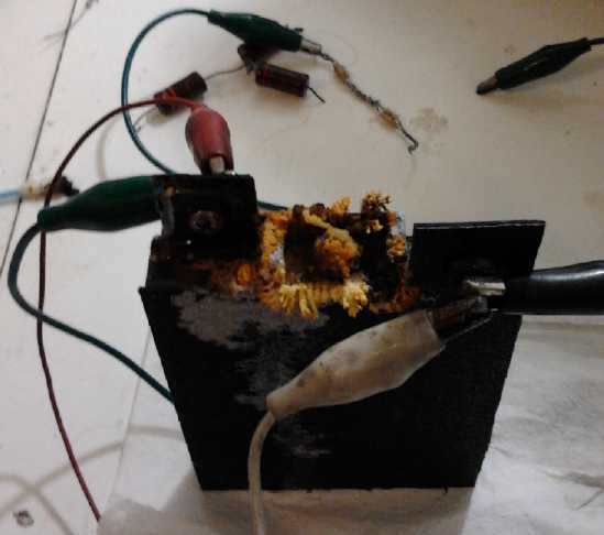
Overcharging (at 3.5 volts) caused this crystal growth... whatever it is
Toward the end of the month I inched forward again
(amongst all the other things) by doing a new 3D plastic case with a
couple more improvements, to be complemented by an improved compactor
and some improved procedures.
Electric Caik Outboard Motor
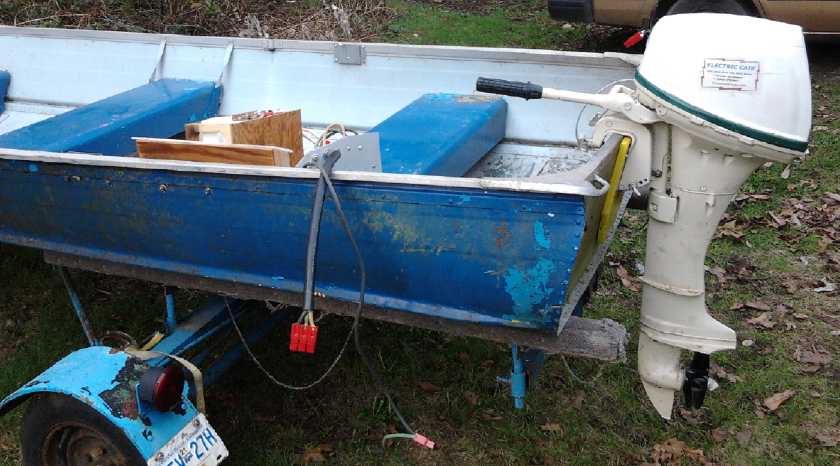
Setting up, Friday. I managed to finish and even scrub off the boat
before launch.
Setting up to run the motor in the Honda 7.5 outboard
shell on the water took first place in construction efforts until the
16th. Starting at the VEVA electric transport meeting on the 6th I had
told
people I would launch the Electric Caik Outboard in my 14'
aluminum boat at 1:30 PM on that date. I finally got everything set up
except an appropriate
speedometer by the afternoon before, and went for a couple of test runs
on schedule. It performed well. The 24 volt motor drew up to 60 amps or
so, about 2 horsepower, and reached over 2000 RPM. In the 2010 tests
the early version of the Electric Hubcap motor drew up to 30
amps at 36 volts (1.5 HP), and only reached about 1750 RPM.
I
must have been going faster this time since the RPM was higher and the
boat was 100 pounds lighter (3 heavy lead-acids versus a NiMH dry cell
battery weighing less than one), but with a strong wind blowing
the boat around it was hard to tell. Someone shot some short video
clips:
I was pleased that the temperature rise in the motor
(after 2 short trips) was
only about 17°C. That means the air flow is good, it's running
efficiently and hence making little heat, and that it'll probably take
the full 3KW I tentatively rated it at continuously without
overheating. That's all the more remarkable when the maximum
temperature is just 65ºC for this motor with all the epoxy
construction. It's an efficient, compact, cool, lightweight powerhouse.
And
it was all but silent. I might be inspired to go out fishing some time!
Perhaps I should mention that the Caik motor can easily be
made as 36 volts, 82 amps instead of 24 volts, 127 amps. (or of course
12 volts, 254 amps. Find your own motor controller for
that!)
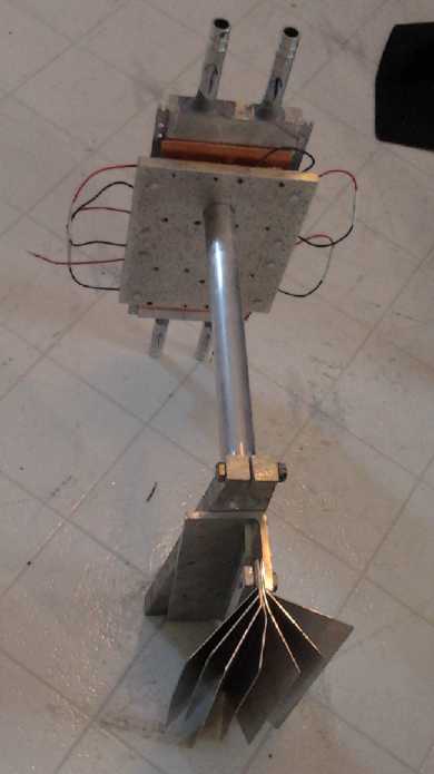
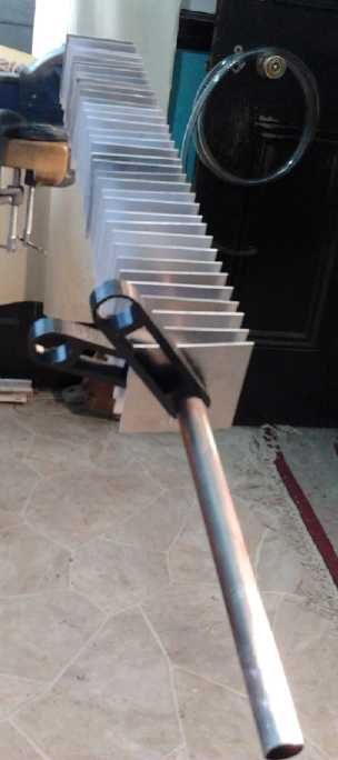
Woodstove Thermoelectric Generator
Radioisotope ThermoElectric Generators (RTEGs) powered by
a hot chunk of plutonium (self heated by its
radioactivity) have long been used in spacecraft going out to Jupiter
and beyond, where solar power from the sun is feeble.
I have just
discovered that TEGs are readily
available in a usable format, after buying a new woodstove and a
Caframo "Eco Fan" that
sits on the stove and runs off the heat of the stove... using a TEG. In
fat, TEG modules look just like peltier
modules, but are optimized for making electricity from temperature
difference (the Seebeck effect) instead of temperature difference from
electricity (Peltier effect). For those who
burn
wood for
winter heat, as is relatively common in this area, it appears a
woodstove thermoelectric generator (TEG) could be a good complement to
solar
PV, since it runs most of the winter when there's little sun -
including at
night.
But it appears TEGs made for wood stoves have been
designed
for surviving peak temperatures rather than for good output with
typical average temperatures of modern low emissions stoves with smoke
igniting baffles, and average
electricity output suffers greatly. This would be a natural tendency of
a TEG device designer who doesn't himself burn wood for daily
heating... or
who perhaps lives in a colder climate where fires are kept hotter. My
design innovates by
using lower temperature TEGs that will produce much more electricity
under typical west coast operating conditions.
The boiling point of water rises with air pressure. My
plan to protect the TEGs when the stove is too hot for them is for a
185 PSI pressurized radiator pipe loop. That will boil
water at 190º, their maximum rating. The steam will rise to a
radiator where it cools and condenses, then runs back down. Below
190º the water will sit in the hot side box unit on the stove, so
no generating capacity is wasted.
Where I get the first impression that most other woodstove
TEG units make up to
around 50 watts with quite a hot fire, I'm expecting up to about 150
watts of electricity from 16 of the 190º TEGs with a moderate
fire. And the stove top could easily fit two such units if more
elecricity was desired. All the heat that isn't made into electricity
(most of it) just
goes out to the room as usual, so conversion efficiency is immaterial
except for defining the overall size and number of parts, and hence
cost, to get "X" amount of electrical capacity.
Peltier Heat Pump for individual room, EV heating: 200% COP!
Peltier Fridge: 1/2 the power for the same cooling!
I got going again on
the heat pump by thinking of potentially better heat radiating
mechanisms with no fan noise. Then I re-read the Cui Peltier Module
datasheets. I multiplied 1/2 times 1/2 and got 1/4 instead of 1/2.
The graph showed (typically) that if the current was half,
the watts of heat pumped
was a little over half. But that's comparing apples and oranges. Then
I related the
current chart to the voltage chart and suddenly realized that half
current comes at about half voltage, and so it was actually one
quarter as much
input power! This suddenly made
Peltier module performance look much better - at lower currents and
voltages. I had heard that they worked better at low power, but I
wasn't seeing the extent until on the 22nd I realized my
error in
thinking. I'd been sucked in by the misleading graph!
The detailed report shows that the heat pump can attain
around 200% coefficient of performance for heating by
driving 15 volt peltier modules with between about 6 to 9 volts, and
how in a fridge, simply putting two of the same peltier elements in
series to drive
them at 6 volts and half the current each will cool it
about as much as a single one (drawing twice the total current) at 12
volts. My 85 watt fridge will drop to under 50 watts!
Driving the Peltiers at lower power means using more of
them, and somewhat larger interface surfaces (more materials), to
attain a given
heating or cooling objective, but that investment will soon be made up
in electricity savings.
Cutting heating energy and cost by 25 or 30% was one thing
-
nice, but not compelling. Cutting it in half, 50% - to replace 400 watt
heaters with 200 - has a lot more appeal. Now I'm really getting
enthused about improving the fridge, and getting peltier heat pumps in
my house in the rooms that use the most electric heat -- and probably
even
working them into professional products, offering them for sale and
making a small enterprise out of it. (Wait, I thought I was doing that
with motors... I'd have to hire someone for this.)

Heat pump with cold side air radiator, warm side liquid.
Then somebody suggested antifreeze would allow a liquid cold side.
This got changed to water radiators for both sides - with anti-freeze
in the cold outdoor side.
This looks about the same as the woodstove electricity generator.
Next: 3D plastic printed cases with copper plates facing the peltiers.
I made the left radiator first. The punch was the perfect size - good
friction fit.
So I decided I needed a proper sheet metal sheer to cut the same size
fins repeatedly
and a jig to get the holes centered (right). Later came fin spacing
clips in 3D
printed plastic.
On the 26th I got on youtube and looked for videos of
Peltier fridges and heat pumps as well as thermoelectric generators.
The words were there in the titles, but when you viewed the videos, a
"fridge" was just a peltier
unit frosting up on a table, and a "heat pump" just meant the basic
Peltier module operating principle. There were a couple of videos where
the ideas sounded good
but the authors didn't seem to quite understand what they
were doing. There was a nicely made beer cooler, a roughly made larger
cooler (beady styrofoam, no hinges) and one guy worked out the
COP for heating up 100cc of water by 22.5ºC (about 2.65! - IIRC)
in 2009, and that was
about as interesting as it got.
So I thought I'd put a video of my fridge up, even tho I
haven't enclosed the heatsink and fan, made the solar day-night
control, or tried out the half power idea. I shot it that evening.
Youtube's 'enhancement' of the rather dim scene is probably an
improvement
but still less than perfect. (The patterned melamine top looks like
rocks at
first!) Anyway it's hi-rez, and it's the only practical thermoelectric
fridge I saw on Youtube. [ http://youtu.be/iCuNBY3hMwI
]
Quitting Magnetic Heat Pumping project
I've decided to abandon the magnetic heat pumping idea in
favour of the Peltier system, which can provide better performance than
I had realized. It's not that it was a bad idea, or that it might not
have a higher coefficient of performance, or
that I feel I might not get there if I persevered. I did get gadolinium
to change temperature with a magnet, and I feel my 'solid state'
magnetic heat pump designs (with moving parts but no liquid or gas)
have pointed to a new
direction for future research and potential product development.
(Perhaps I'll do a youtube video.) It's just that I have far too many
projects. I can make magnetic prototypes, or I can make working Peltier
heat pumps as products that might start saving homeowners electricity
next winter. If the whole thing wasn't just one area of many I'd try to
do
both.
There's one further consideration: if someone should come
up with a Peltier module with better thermocouples - perhaps find some
junction materials superior to bismuth-telluride, performance could
rise to a point where the simplicity and longevity of a solid state
device would simply make magnetic and compressor based heat pumping
redundant except in (or even in?)
large systems. Achieving a 'typical' COP of 3 would accomplish that. I
don't know that that'll happen but if it did probably my existing
designs, or modified versions of them, would simply work better with
the improved parts.
In Passing
Incidental news, editorial comments & opinionated rants
In discovering that the world isn't the
stable, stately place I used to think is was, in a couple of my recent
newsletter editorials I got pretty excited about what might happen, and
how soon. The population is in a bubble and looks like it'll shrink,
the financial
system is bound to crash, and the USA obviously can't go on as it's
going. One sees what must happen in broad outline, and yet the
sequences and timings and
what straw breaks what camel's back, or if the camels just lie down or
something,
are pretty unpredictable.
Viewed in retrospect, these things will no doubt seem to
have occurred in the blink of an eye, but in the present, event follows
upon event in an unforeseeable sequence that may take a decade or more
to play out - we have only to
look
at the protracted woes of Greece or Palestine and think they must
surely end, but they go on and on. Hopefully the population drop will
be gentle and trouble may largely overlook
less crowded regions, tho one suspects not. Money will have to
be recreated in some form - hopefully as an honest, sustainable system
without institutionalized robbery built into it. And the nation that
brought us the silicon chip, went to the moon, and created the internet
is as likely to
reinvent itself in new form as to break up. Only the financial crash is
almost certain to be a sudden, full blown crisis, because everything
that's being done to put off the day is making it so it'll be worse
when it happens.
Viewing the facts, a few negative circumstances do stand
out:
* The population seems to be "in a bubble". Perhaps not so much in the
Americas or Australia, but other regions on other continents seem
seriously
overpopulated. All financial and economic bubbles burst, and this
bubble seems
poised
to do so as well. China's one child policy has
doubtless had considerable beneficial effect there, and India has been
overtaking China as the most populous country in the world. But
together they have 1/3 of the world's people. Almost
everywhere, there seem
to be too many cities that are too large and with tenuous supply lines,
vulnerable to any interruption.
A small number of nations such as Indonesia and Nigeria are still
procreating prolifically. This can't work out well. It's said that when
people are spending 40% or more of their income on food, revolutions
break
out, and that this has been an under-reported factor in the "Arab
Spring" uprisings. And when conditions
get bad enough, disease epidemics are almost bound to break out and
wreak
havoc too. In an
increasing number of "more advanced" lands, family size has shrunk to
or under replacement levels, but owing to increased life spans
the
effects of this are slow of realization.
* The world economy has also been "in a bubble", the need for goods and
services growing with the expanding population. This is now collapsing,
in large part part owing to extreme inequitable
distribution of
wealth (youtube: "Wealth Inequality in America"), but it will get worse
regardless. When the population
starts to shrink,
there'll probably be more than enough material goods for everyone, and
so much less
need for new goods, and especially for new housing and expansion of
civic infrastructure. Except for food, energy and clothing,
improved technologies and superior products may become - if they aren't
already - the only flourishing areas of production.
A possible exception might be large scale investments in
infrastructure (such as
electric rail transport and 'green' electric power)
if those who wish to build a better future are able to grasp the reins
of governance. But for progressive people to get into decision making
positions gets into improving our social and economic governing
structures, which won't happen before a big crash.
* The financial system is in some bubbles of its own making, and it is
one area where a sudden and probably global crisis is likely to strike.
There was the "dot
com"
bubble, then the "housing bubble", now the "bond bubble" is global, and
currency
itself is inflating itself to oblivion and will soon need drastic
revisions.
Having privately owned central banks print money on behalf
of
countries and then lend it to them and charge interest on the
money they simply conjured up, is a huge pyramid scheme that was
foisted
on
everyone long ago by greedy people, corrupt or indifferent leaders, and
a complacent
public. It's been perpetrated by cunning and persistent schemers to
make themselves fabulously wealthy. It was and is enabled by general
lack of education about how finance works and even about what money is,
and it's largely to
blame for present day ills.
---
Usually economic charts are pie graphs, where everything
is "equal" except in percentage. Someone sent a
link to
the interesting one below, which shows how food and energy production,
natural resource extraction and transportation and storage of goods,
the parts of the economy essential to the maintenance of all else,
forms
an inverted pyramid. Without that seemingly trivial food sector at the
bottom, less than 1% of the economy, we all die, so the thin edge of
the wedge - the farmers - holds the rest of
the pyramid up. The fact that oil and gas are vital to food production
and distribution shows why we need to get on to electric farming with
CNC farming and gardening machines, electrify the railroads for freight
and passenger transport, and finally move to electrify all vehicles
and
vessels. At the "top" of the pyramid, the financial sector should only
exist at all to serve the rest of the
economy. It sector should be as small as is consistent with
that mandate. The government should be at least large enough to
ensure no one can take advantage of anyone else. But those in charge,
using the "revolving door" between corrupt government and finance, have
figured out how to extort so much wealth from everyone else that they
have become cancerous parasites that dominate the economy.
And I think it must be an old chart. Evidently the
unregulated
shadow
banking system is now much larger than the rest of the economy combined
(notwithstanding that the big banks are insolvent, ie, they have more
liabilities than assets). Governments have swelled, and in the
west manufacturing has much shrunk, making the pyramid even more top
heavy and parasite ridden than shown. The pyramid is probably a good
indication of the symptoms of what's wrong with our unsustainable
society.

Now back to that trivial little part of the economy, food
production. If - when - Monsanto's patented GMO pollen blows into your
field and contaminates your crop seeds, you have to pay royalties to
Monsanto for using their patent. That means most all farmers,
everywhere, are paying Monsanto royalties on the unwanted
contamination, and unhappily growing GMO foods to boot.
There was a big court case about it in Canada (15-20
years ago?) - Monsanto detected their GMO genetics in the crops of a
farmer who had never ever had any dealings with them and hardly knew
their name, whose family had grown their own seeds for generations -
and Monsanto won. The farmer, a well-spoken and articulate man, lost
the family farm. This set the precedent for this tyranny. In India
farmers had to fight a huge court battle to regain the "right" to grow
their own seeds at all.
I've heard that some farmers lately - even in India - have
given up and even committed suicide because they're all pressed under
the thumb of Monsanto and their global GMO experiment. And yes, it
seems those GMO foods are causing at least a few people serious health
problems (allergies at least). How many health problems then are being
caused
by them but the link hasn't been discovered - or admitted - yet?
Evidently over 1/2 of
US children now have chronic health problems. ...Well, here's an
alarming piece in my e-mails just as I'm finishing up this newsletter:
it says
"An Italian study found that Monsanto's NK603 genetically-modified (GM)
corn causes serious organ damage and tumors in mammals."
and
"Based on earlier research involving the link between viral genes and
plant and human health, the new discovery raises serious concerns about
the safety of many GMOs in commercial production today."
http://www.ubalert.com/bwwb?open_ctab=1
http://www.naturalnews.com/038998_GMO_crops_viral_gene_organ_damage.html
This probably won't hit the US news at all. They know Monsanto will sue
them if they broadcast it.
And I hear Monsanto has recently purchased every major
garden seed company. It may get very hard to avoid GMO foods even in
your own garden. Latest news is that while bugs are adapting to thrive
on GMO foods that were immune to existing pests, Monsanto is blaming
the
farmers for recent poor
GMO crop yields.
---
Ever think of a good "comeback" or response just after, or
long after,
the time to say it has passed? (There was one that kept annoyingly
popping into my mind for a decade, until one day I finally thought of
the
perfect response for what was said ten years previously that I had
answered so lamely. Ever since then, I can't even remember what the
subject
was.) Now I've thought of a great ending to last
month's
little piece on arms: "Guns don't kill people, Americans kill people."
Of course, most people everywhere including the Americans are good
hearted...
but that's where
so
many violent death stories in the news originate, from shooting sprees
by depraved individuals to drone strikes killing hundreds (4700+ so
far
according to a senator supporting the strikes) by the present
administration.
Electric
Hubcap Motor Systems - Electric Transport
Electric Caik Motor
'Honda 75' Outboard Conversion
(a motor with many scratches but not made from scratch)
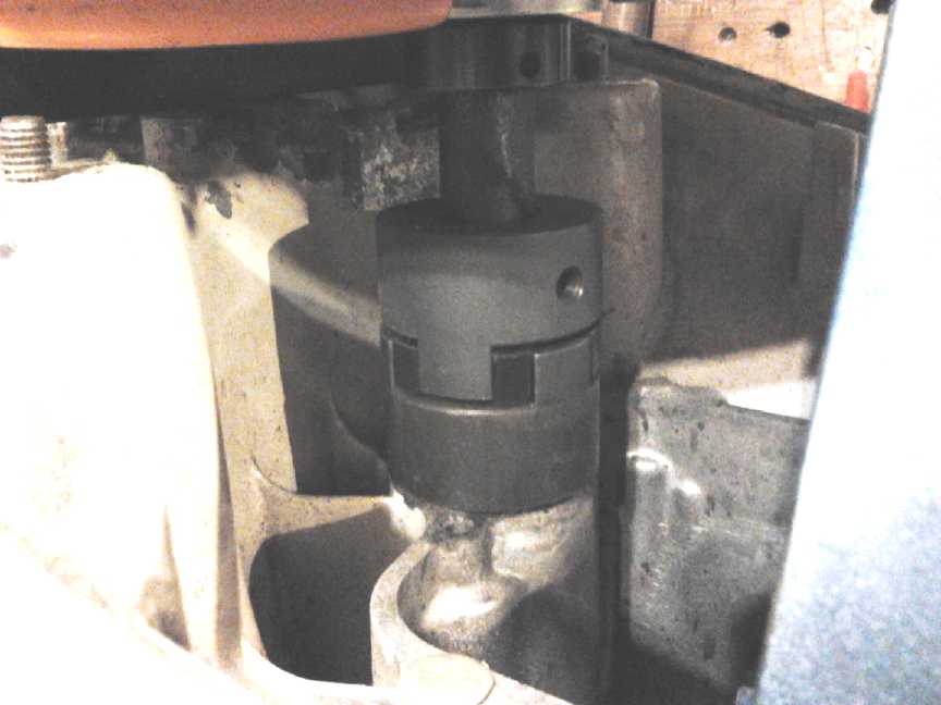
Flexible 'joy coupling' connects motor shaft to outboard drive shaft.
Luckily, a 1/2" square steel rod fit in the drive shaft's socket, and
with
the corners a little ground off, in the joy coupler.
On the evening of the 2nd I discovered how little work would be needed
to mount the Electric Caik motor in the Honda 7.5 outboard shell. On
the morning of the 4th I had it in. It wasn't my idea of ideal,
but the shafts lined up well and in a retrofit it's often far simpler
to go with the flow and cludj things in than to do it in an ideal way.
(In other words, I don't think it'll fall apart on the water.
In the event it seemed pretty solid.)
Theoretically I could have thrown things together and
taken it out that very day. But I decided to be more methodical. I
wanted the controls right on the outboard this time - a twist speed
control on the arm and the forward/reverse switch on the case - instead
of in the motor controller on the seat. (Later I measured and it looked
like I could (just) fit a controller under the hood with the motor.)
In addition, the plywood motor
mounting board on my boat's transom was virtually rotted off. I cut a
new one after the trip in 2010 but hadn't painted it or put it on.
(It's all the
newer now.) And I wanted RPM, current, temperature and voltage meters
nicely set up.
On the 6th I tried running it dry, and then in a garbage
pail of water. It seemed quite solid and smooth. Forward was pretty
quiet (unlike in 2010 when the motor shaft was pressing downward on the
leg drive shaft), but in reverse (motor running backwards) there was
notable gear noise. So what? Turning at 2000 RPM dry took about 16 amps
- 1/2 a
horsepower. The motor alone took 5.7 amps last month, showing the
friction in the outboard drive mechanism is eating about 1/3 of a
horsepower.
It was pathetic seeing how slowly the prop turned with the
motor racing away. To eliminate that nasty gearing down is of course
the main reason I want to build the 'outboard from scratch'. And maybe
it
could eliminate most of that 1/3 of a horsepower of wasted energy.
Hitting 2000 RPM wet took around 40 amps - 24 more than
dry - showing it took 3/4 of a horsepower to churn up a storm in the
water in the pail. After a few moments of this, I felt the MOSFETs in
the motor controller. They were actually slightly warm.
Then I took it to the VEVA electric transport meeting in
the evening and ran it (dry) in the parking lot as a demo. I announced
that I'd launch it at 1:30 PM on Saturday the 16th, and I told a few
other people in the next few days. I spent a good portion of the next 9
days getting things ready.
I painted and put the new piece of plywood on the back of
the boat, installed a potentiometer in
the outboard's steering handle to replace the throttle cable and a
Fwd-Off-Rev switch on the front of the case, made a box with plexiglass
to hold meters for amps, volts, motor temperature and RPM, got a pitot
tube with a speedometer, reconfigured the batteries from 20 AH at 36 V
to 30 AH at 24 V, licensed the trailer, put a circuit breaker in the
motor controller and fixed the RPM signal trace (long overdue), wired
the necessary plugs and cables, and made two labels for the motor. I
meant to make a housing and tie in two 100 amp-hour lead-acid
batteries, but I ran out of time. The 30 AH NiMH, 60 D cells, would be
enough for a
test.
Friday prep.
On Friday I
put it all together in the boat. I
found I had
managed to wire three of the cables wrong, but nothing blew up and I
got it all running before the afternoon ran out.
One unsatisfactory feature was the speedometer. It read
from about 15 to 60 'mph', with lower speeds hardly moving the needle,
and the boat wasn't going to hit 15. Evidently they're only made for
high speed speedboats. Blowing into the tube I couldn't make enough
pressure to get the needle up to the first mark -- there must be some
transducer to work with much lower air pressures in the tube. Aircraft
pitot tubes also must surely work at much lower pressures, since
they're in air and not water. There were paddlewheel speed indicators
available, but they were too costly to consider.
Saturday had a lot of weather. It started out as a
beautiful morning with (gasp!) full sunshine, but clouds rolled in and
around noon another unusual phenomenon, strong wind, sprung up. When I
got to the boat launch at 1 PM, everybody was bringing in their boats.
I was still planning to launch in the sheltered little bay, but someone
thought it was too windy. There was some discussion and we talked for a
while. We shot a little video where I showed the various components.
[http://youtu.be/zrtE6yHSFRw]
Finally I decided the launch had to go ahead. It was a small,
light boat, and four of us could surely manhandle it around regardless
of wind.
 The wind
pushed the bow of the boat
around and nearly blew it back against the jetty as I headed out.
[http://youtu.be/jen-WpfaM4k]
When I finished concentrating on that I glanced at meters. I
was surprised to see the motor over 2000 RPM and drawing almost 60
amps. I had meant to keep it under 30 amps for the first trip, which
was the maximum value I'd used in the November 2010 trip with the
primitive version of the Electric Hubcap motor. (That one used the
second
stator ever made - oblong nail strip core coils on a lossy steel rotor,
and a 9" rotor that *just* fit inside the Honda hood.)
The wind
pushed the bow of the boat
around and nearly blew it back against the jetty as I headed out.
[http://youtu.be/jen-WpfaM4k]
When I finished concentrating on that I glanced at meters. I
was surprised to see the motor over 2000 RPM and drawing almost 60
amps. I had meant to keep it under 30 amps for the first trip, which
was the maximum value I'd used in the November 2010 trip with the
primitive version of the Electric Hubcap motor. (That one used the
second
stator ever made - oblong nail strip core coils on a lossy steel rotor,
and a 9" rotor that *just* fit inside the Honda hood.)
I cringe because I've had so many of my motor controllers
blow up at high amps, but this one has been very faithful and has done
100, tho only momentarily. And
running 24 volts instead of 36 should be easier on it. At 30
amps, I could hardly keep the boat headed into the wind, and I had to
up it to 40. It seemed the motor had less push per amp. It finally
dawned on me that the previous motor was 36 volts and this one was 24,
so the current to match the previous 30 amps was now 45, power being
volts
times amps.
With the strong wind it was hard to compare speed mentally
with
the 2010 trip, and I was disappointed - I thought the boat was going
slower. But it was the
same outboard shell and the same prop, and the same boat was about 100
pounds lighter with the NiMH battery instead of 3 big lead-acids, so
the same RPM had to be at least
the same speed on average, and probably a little faster. Last time the
motor was
about 1700-1750 RPM max, and
this time it was over 2000, so it had to be going somewhat faster.
And there
was, if not a wake, more turbulence behind the transom than I
remembered.
[http://youtu.be/-L3yHhgoFmE]
Towards the end of the second little trip, with two of us
on board, while drawing a high current like 60 amps, the 30 amp-hour
battery was down to 20.8 volts. I'll want more cells in parallel next
time to handle the currents better, which will improve the range more
than simple addition of the amp-hours adds up to. And before I head out
on a real trip (fishing?), I'll want to see how long it really will run.
I seemed hard to gauge efficiency. But on the second trip
I looked at the the motor temperature a few times. It sat at about
300-301ºK (27-28ºC) and wasn't rising. Since it was around
10ºC out, that's a rise of just 17-18º, pushing 40-60 amps or
up to 1.44 KW (2 HP). The low rise indicates (besides good airflow) not
much heat generation, which indicates little power is being wasted
inside
the efficient motor.
"Best under" temperature for the coil cores and the epoxy
is 65ºC. If it was 20º ambient, that's an allowable rise of
45º. So it looks like the motor could probably run continuously at
my originally estimated rating of 3 KW without overheating, except
perhaps in
hotter weather. And I could always drill some more airflow holes in the
rotor end - they're pretty few and small as built. I couldn't try
higher current and power on this trip without over-revving the motor -
and probably over-stressing the battery.
Next I'll want to try one of the scuba unit design
propellers to see how much difference that might make to performance.
I'm expecting lower amps to achieve the same boat speed. Now, about
measuring boat speed...
Measuring Boat Speed
I found a pitot tube that should give boat waterspeed, but
the speedometers went from 0 to 60 miles per hour, and the first
marking was at 10 and the next at 15. I had to blow awfully hard to
move the needle at
all, suggesting that the problem wasn't the pitot tube but the
insensitive speedometer. In the rush of events, I didn't even mount it
during the boat test, and I doubt I'd have seen much on it if I had.
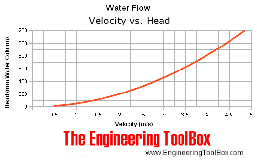
I looked everywhere for a chart of the Faria pitot tube's
speed versus pressure, but found nothing. Finally at
"EngineeringToolBox.com" were some graphs and tables.
I was
thinking that every pitot tube design would be different, but that's
really not the case. If there's a hole in the front end, the dynamic
pressure must depend only on the speed, so the figures would apply to
all. Hence any speedometer will go on any front-end pitot tube. The
size of the hole and piping behind it would only make a
difference in how fast that pressure equalizes when the front end
pressure changes, not to how high the water finally rises in a vertical
column tube. (Let's see...
there's 3600
seconds/hour and 1000 meters/kilometer, so 1 m/s = 3.6 Km/h.)
The table below shows the head obtained at different velocities
(conveniently in feet & feet/sec,
contrasted to their two graphs in meters & meters/sec, and in
inches
& feet/minute). Evidently, all
one needs to do is use transparent tube, make it into an open topped
vertical column
from the waterline up, do the
necessary conversions, and mark off the velocities on the tube or a
white surface behind it. Then it should be possible to get pretty
accurate velocity readings down to maybe 2 or 3 miles per hour,
depending on the accuracy of the height readings. This can go up to the
speed of however high the tube is, above which speed water will spew
out the top. Of course one could plug the top end and get a
more linear scale, but column height versus air pressure above the
column would all have to be worked out for each speed.
The one catch to this is to keep the measuring stick base
at the
waterline level, which naturally varies considerably. Perhaps one way
to do that is to put a 'trim tab' with a float out the
back, which would go up and down with the water level.
The tube could attach directly to this and be situated
behind the transom, but then you'd have to lean over the back of the
boat to read it. (How many people have drowned from peeing off the
back of their boat and falling in?) A better way might be to have
something like a coat hanger wire bent in an upside down "U", with the
outside end on the float, coming over the transom, and down again at
the rear of the boat. The base of the measured tube section attaches to
the inside end. No doubt there are a zillion possible variations on
this theme.
Velocity Velocity Head
- v - - v^2/2g -
(ft/sec) (ft of Water)
0.5 0.004
1.0 0.016
1.5 0.035/10.6mm (1 MPH = 1.46667 ft/sec)
2.0 0.062
2.5 0.097
3.0 0.140 (2 MPH, 29.6mm)
3.5 0.190
4.0 0.248
4.5 0.314 (3 MPH, 95.7mm)
5.0 0.389
5.5 0.470
6.0 0.560 (5.86f/s=4MPH, 171mm)
6.5 0.657
7.0 0.762
7.5 0.875 (7.3333f/s=5MPH, 267mm)
8.0 0.995
8.5 1.123 (5.8MPH, 342mm)
9.0 1.259
9.5 1.403
10.0 1.555 (6.8 MPH, 474mm)
11.0 1.881 (7.5 M/Hr)
12.0 2.239 (8.2MPH, 682mm)
13.0 2.627 (8.9MPH, 801mm)
14.0 3.047
15.0 3.498 (10.2MPH, 1066mm)... Wow, after
converting units, this actually agrees with the graph above!
16.0 3.980 (10.9MPH, 1213mm)... I'd probably be
doing really well to hit these speeds?
17.0 4.493
18.0 5.037
19.0 5.613
20.0 6.219
21.0 6.856
22.0 7.525 (15 miles/hour, 2294mm)
My take at the moment is that for speeds of about 2 or 3
up to 10 MPH, the system with a vertical tube a meter or more long
would work well. Above 10 or 15 MPH (if I get there - probably with the
'outboard from scratch') a stock speedometer could be used and the
waterline is of little consequence. Hovering around 10MPH might be
annoying to measure. I think you'd want a tube with a stopper on top,
and would have to do (or find) the calculations for height water for
each speed.
Future Caik Outboard Runs
The outboard with the Caik motor seems like a keeper, and
I'll be taking it out again and checking out the speeds attained... and
a 9" shortened cast aluminum or PP-epoxy version of the scuba unit
propeller, assuming I make one successfully. With some more amp-hours
of batteries on board, and perhaps a couple of large 12V solar panels
forming a roof at the front, I might even go out fishing!
A final note: It would be surprisingly easy to over-rev the Electric
Caik motor
and the gearing down of the prop prevents being able to use full power
without over-revving, but I do have one safety in the outboard as done:
I put a 50 amp circuit breaker in the motor controller. It didn't blow
at 50 to 60 amps and
somewhat over 2000 RPM, but it surely would have by about 70 amps
before
hitting 2500 RPM or so. I had the Caik running up to 2700 on the bench
and that didn't bust it. So I probably have a boat that won't
blow up
with the first mistake on the throttle. But I keep thinking I should
come up with some way
to strengthen the rotor so I'll feel comfortable taking the motor up to
at
least 3000 RPM.
Before the end of the month it occurred to me I might try
reducing the supply voltage to 18 volts from 24. That would drop the
maximum RPM, probably to a reasonable level. Currents would be 4/3
higher, but it wasn't drawing near the limit anyway. (Of course, I'd
have to find a higher rated circuit breaker.) Or, the potential 36 volt
Electric Caik version could be run at lower voltage... like
24... really, I want that outboard that isn't geared down!
PGTC
Car Transmission
Centrifugal Clutch for Sprint
Car Torque Converter Transmission
System
Suddenly on the morning of the 14th, I had the idea of
using a centrifugal clutch instead of the manual clutch system I was
making for the Sprint car. That seemed to hold the promise of magically
leaping over a number of hurdles. Why hadn't I thought of it sooner? -
perhaps it was just as well I hadn't
gotten any farther than I had on the clutch construction?
I found the centrifugal I tried on the motorbike a while
back. The idea was right, but the shaft size was wrong. So as I was
going shopping to buy a breaker for the motor controller for the boat
anyway, I made the trip out to Princess Auto, and indeed I found a
somewhat heftier looking one with 1" shaft bore, 'on sale' for 30% off
- 70$ plus tax. It said "1800 RPM". Doubtless that was the RPM where it
engaged rather than a performance limit. I'll probably have to do
something to reduce the 'engage' speed. Half might be good. Could I
simply take out two of the four spring clips on the shoes?
It was also pretty wide, sporting a fat V-belt pulley
instead of a narrower chain sprocket. It started to look like
I'd have to change the mountings to accommodate it.
Sure enough, I milled the keyslot in the
shaft to the end so it, with its built-in keyshaft, could slide onto
it, and found it was a bit too wide. Thus an impass was created where I
wasn't sure what I should do next, and I worked on other projects. Only
on the last day of the month did I think that I should go back and
trade the clutch for one with a chain sprocket - it would be just that
little bit narrower that it should fit. Furthermore, the one with the
V-belt pulley (that I wasn't going to use) had no solid way to prevent
a plastic flat belt pulley from slipping. However, the pulley could be
printed with a shape that fit between the chain sprocket teeth and so
lock it to the clutch rotation. With either one, there was no provision
for attaching anything, and I'd have to open the clutch and put in flat
head bolts from the inside sticking out the side. Somehow I still had
the package, intact, so I could take it back and do the swap, which I
did on March 1st. The one with the sprocket was 45$ more, but trying to
use one that was causing headaches was false economy. The new one fit
on. It was just as long, but thin at one end, which protruded into a
hole just far enough to replace a couple of spacers, placing it just
that bit farther along the shaft that it fit.
Getting the Sprint car going is definitely on my short
list of things to do. It's sat out there immobile for two winters now,
while the day of petroleum shortages and high prices draws on apace!
And the weather to work outside is ahead.
Electric Equipment Projects
Peltier Element Heat Pump: Good COP (200%) is attainable!
A re-reading of the charts in the Cui Peltier Module
datasheets led to a reassessment of the potential for a peltier heat
pump to save electricity. It now appears that if optimally designed, it
might put out twice the heat of an electric resistive heater for the
same electricity input, at outdoor temperatures somewhat above
freezing. This is a very significant cost and energy savings for
the many people who heat with electric heat, and doubly so for electric
vehicles, whose range is decreased by the electricity used in heat and
window defogging.
Furthermore, a peltier fridge can be made to use half the
electricity mine presently uses for the same cooling power.
The key, as detailed below, is to run the peltiers at
about 40 to 60% of their maximum voltage, such as 6 to 9 volts for a 15
volt rated
unit.
The construction of the heat pump being somewhat
frustrating as it was made, not to say problematic, I hadn't done
anything more on
it since fall, while the heating season has come and is now gradually
going. But in considering the makings of the thermoelectric generator,
so
closely related in makeup, I had the idea to use a hot water pipe
radiator with thermoconvection circulation instead of heatsinks and a
fan. I'm not a big fan of fan noise - I wouldn't put one in my bedroom
where I often use the most electric heat - and a pipe seemed very
adjustable.
Then longer the radiator pipe - which could easily be any
length - the lower the temperature would be returning to the unit, even
down to room temperature. Total heat pumped per watt of electricity is
highest when the temperature spread between hot and cold is least.
My original idea for doing water was that if the
outdoor side temperature was 5ºc and the water
kept the warm side down to 25ºc in a 20º room, the spread
would only be 20ºc and each 8.5A Cui Peltier unit would deliver
about 50 watts of heat pumping while drawing about 7.2 amps at 12 volts
- 85 watts of electricity. That would be 135 watts of heat to the
heated space for 85 input watts, or about 160% COP. Expanding on
that: 1500 watts of heat for just 950 watts of electricity. (with about
12 Peltiers in series if it's to run off 120 VAC. 3 per set in a 36V EV
would each be just under 400W of heat for 245W in.) This contrasted
well with a warm
side temperature of 35ºc for the heatsink and fan, resulting in
about 140% COP.
Those figures seemed like the best that would be
attained... before I realized that the higher efficiency of running
Peltier modules well below their ratings allows for 200% COP's.
Either way, I'm making a
considerable assumption that the water in the pipe will exit the unit
at 25ºc and not need to be warmer to generate enough flow
thermally. There's always a small pump...
Ideally from a thermal point of view, one would use copper
for all the heatsink parts and piping. It's the best heat conductor of
any element (except silver - slightly better but rare), and it can be
soldered to. But it's costly
and heavy.
The construction I had in my head at that moment would use
a
fat aluminum main warm side plate. Some copper plate strips, maybe
1.25" x .064", would be each soldered along one side of a copper pipe.
The
strips are then bolted to the aluminum plate to transfer the heat from
it to the water in the pipes.
Alternatively, square, rectangular or oval copper pipes
(if available) could be sandwiched between two pieces of aluminum. That
was when I flattened a copper pipe for this purpose:
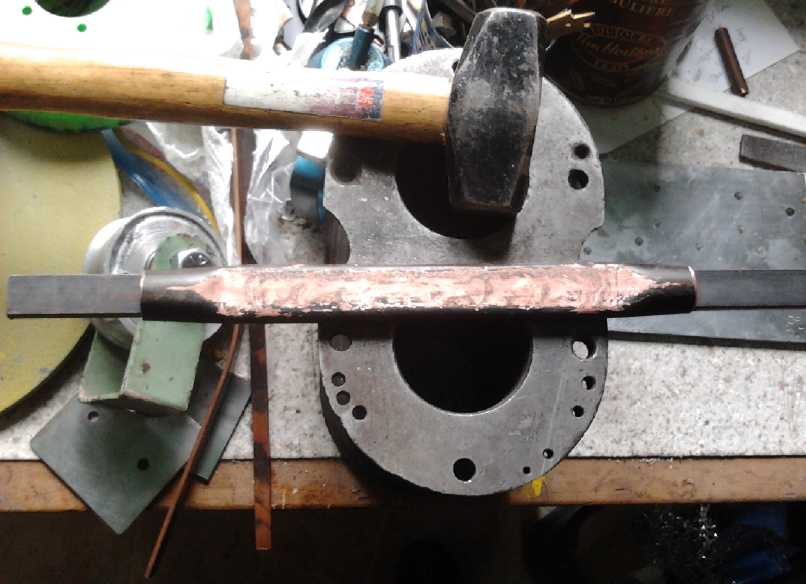
An idea for flat copper pipes. (3/4" pipe)
This looked very good after sanding the flat part flat.
Say!... This still might be a productive idea - but as a one-piece
replacement for a water box
if a pipe wide enough to mount a Peltier module on when flattened
(ie 40+ mm) was employed.
Hmm... 1-1/4" works! Must get more than this one 9" piece!
Peltier Heat Pump Efficiency is much better if driven softly - over
200% COP!
On inspecting the performance curves of the Cui Peltier
modules again, for the first time I related the voltage graphs to the
current graphs, which are shown separately, and working out the input
powers, came up with quite
different ideas of the efficiency a Peltier module could have than I've
previously held. The performance at lower currents is better than I had
believed, and the idea of Peltier heat pumps and fridges becomes more
attractive.
My mistake had been to unthinkingly think that half
current was half power. But half the current is attained at half the
voltage, which means it's 1/4 the power.
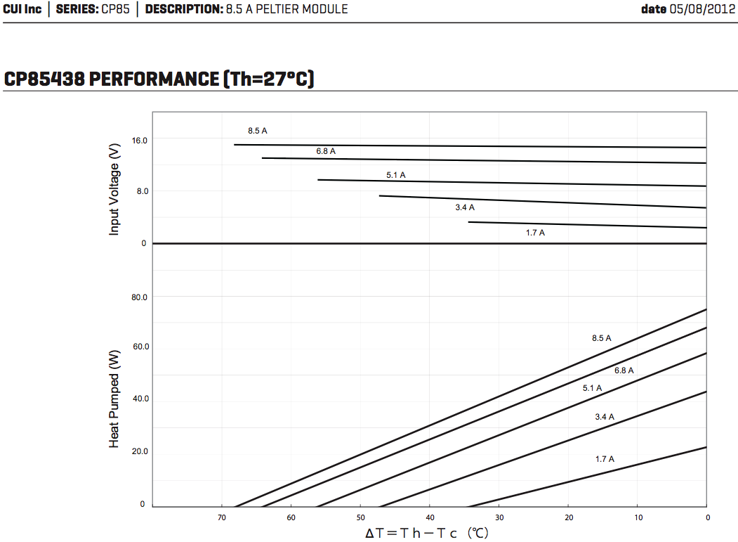
Cui 8.5A 15V Peltier Module -
performance at 27º hot side.
From the datasheet graphs, I worked out coefficient of
performance (COP) for different currents at 10º, 20º and
30º temperature spreads. (Voltages were read from the above graph
for 20º spread, but they only change a bit for 10 & 30º.)
Amps (given)
|
Volts
(from graf 1)
|
Input Watts
(V * A)
|
Heat Pumped @ 10º spread
(Watts, graf 2)
|
Heat Pump COP @ 10º
(heat: watts out/watts in)
|
Heat Pumped @ 20º spread (Watts, graf
2)
|
Heat Pump COP @ 20º
(heat: watts out/watts in)
|
Heat Pumped @ 30º spread (watts, graf
2)
|
Heat Pump COP @ 20º
(heat: watts out/watts in
|
1.7
|
3.2
|
5.44
|
17
|
413%
|
9
|
265%
|
3
|
155%
|
3.4
|
6.3
|
21.42
|
35
|
263%
|
26
|
221%
|
16
|
175%
|
5.1
|
9.0
|
45.9
|
48
|
205%
|
38
|
183%
|
27
|
159%
|
6.8
|
12.4
|
84.32
|
58
|
169%
|
47
|
156%
|
36
|
143%
|
8.5
|
14.7
|
124.95
|
62
|
150%
|
53
|
142%
|
42
|
134%
|
One's first impulse from this table might be to put
as many Peltier elements in series as possible to attain the highest
coefficient of performance - which looks almost as good as a
compressor/refrigerant unit. However, if the temperature difference is
increased to 30º (-7 on the outside), 1.7 amps only pumps about 3
watts, dropping to zero at about 34º spread. There 3.4 amps is
more
efficient. I'm inclined to go with 6 to 9 volts per 15Vmax peltier, say
2/5 to 3/5 of the rating.
That will up the initial expense but will pay back in electrical
savings over a heating season or two. maybe 3.
Better Peltier Fridges &
Peltier Heat Pumps with Evacuated Pipes?
The picture seemed brightened on the 21st when someone
told me how to
make an evacuated copper pipe with a bit of water in it on the 21st.
Evidently if the bottom of the pipe is heated, the instant steam
instantly
transfers the heat throughout the tube, thousands of
times faster than the copper itself.
This should mean that the warm
side of the unit can be kept only slightly above room temperature using
sufficient finned copper pipe. This augers well for getting the 160%
heating efficiency, tho the radiator pipes will hardly feel warm.
Likewise the warm
side of the Peltier fridge's unit can be kept cooler, to do more
cooling with less electricity. With the finned heatsink and
fan, it stays around 35ºC in a cool room. With sufficient
evacuated water pipe with
fins, it might be kept down around 25º and the fan noise could be
eliminated. It would need to run somewhat less time each day, or the
peltier module might be dropped to the next lower current rating.
I've written
more on this under the closely related Woodstove TEG project in
"Electricity Generation" below.
Of course
compressor refrigerant fridges and heat pumps are still higher
efficiency. The attraction to Peltier solid state units is simplicity,
robustness, portability, and reliability for 12 VDC operation. DC
compressor fridges have a reputation for short life. Magnetic heat
pumping has the potential to be at least as efficient as compressor
technology if not better, and probably more portable.
And of course, the heat transfer of evacuated pipes is
only better by degree than simply having water circulate by convection,
which is only better by degree than a finned heatsink and fan.
The Actual Peltier Heat Pump
On the 20th I
found a grungy
3/8" aluminum plate about the size I wanted (5" x 6") and sanded it
flat and smooth on the belt sander. 3/8" is a good heat
distributor, and it's thick enough the bolts on one side can thread in
securely without sticking out and being in the way of things on the
other side. Then I dug out some
pieces of
copper pipe and fittings from a 30+ year old box, from when I had
plumbed the house.
I didn't expect to take it any farther, but by the 25th I
had some basic design details firmed up in my mind. It occurred to me I
could finish a basic working unit before the end of the month, install
it in my bedroom (where I use the most electric heat), and use my lab
power supply to run and test it.
The design details (as built) were:
* The 3/8" plate as the cold side base for the whole unit.
* One or two 7/8" round aluminum rods to transfer heat from the plate
through the wall to the outside, needing only a hole (or two) drilled
through the wall, rather than cutting a large opening.
* A fat aluminum bar clamped on the outside of the rod(s), holding the
finned outside heat sinks previously made. (Water outside would freeze,
hence an air only system.)
* A copper box of water covering the unit, taking the heat from the
warm side of the 6 peltier units.
* A copper pipe radiator against the the wall above the unit, cooling
the water, which would circulate by convection from the box.
The secrets are in driving the Peltiers lightly, and in
excellent heat transfer surfaces and radiators. The better the inside
radiator is, the cooler it stays warming the room, and the better the
outside one is, the closer it is to the outdoor temperature. Such good
heat transfer keeps the temperature spread across the Peltiers to a
minimum, which as the graph shows, makes them the most efficient.
On the 25th I set up the CNC machine and made a pattern of holes. I
drilled out the 3/8" plate. I made the same mistake as with the
previous one: I put the Peltier mounting holes where they would
conflict with the heat radiator holes on the other side. Then I bought
7/8" aluminum rod. I drilled a 7/8" hole in a piece of test aluminum.
The hose had to be just right to fit the rod tightly to give excellent
transfer of coldness from the plate to the rod. I feared the rod would
fit loosely, but it was very close. I drilled out the 3/8" plate and
inserted the rod. I could still wiggle it a bit. So I took it out and
pounded on the end with a hammer for a bit to mushroom it out. Then I
had to pound it on, and it wouldn't move. Good! I sanded it flush with
the plate as peltiers would overlap it.
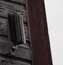
As for the pipe radiator fins, I couldn't find them.
Evidently they're only stocked as whole radiant wall heaters complete
with covers. I found some fins that wrap around the pipe along its
length, but that would be much less radiance per meter of pipe.
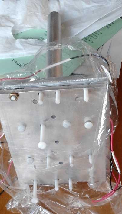
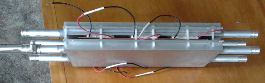
First Design, with air radiators on both sides
Assembled unit with water box warm side, air & conduction cold side.

Heat pump with inside warm side water box to go to radiators,
mounted on wall with cold side aluminum rod going through the wall.

Outside of wall with aluminum rod poking through.
& with radiator fins attached.
On the 26th, after I'd
bought a sheet of copper and as I
was working on the unit, the parts for my woodstove TEG arrived. I
looked at the liquid plates and immediately saw that one of them would
be the ideal thing for the heat pump warm side. I exchanged the
aluminum cover plate for copper to improve the heat transfer from the
Peltier warm sides - the most critical point - and set to work on the
improved unit.
I drilled the hole through my bedroom wall in the evening
and hooked things up with plastic tubes. It leaked at the copper plate,
I had the peltiers the wrong way around, and worse, the heat from the
outer plate hardly seemed to come through the wall to the outside. (I
had put it under a window so I could reach out and touch it or get
temperature readings without standing on a ladder outside.) I was
disappointed by this evidently poor heat transfer.
Then on the 27th I had coffee with my friend who had
worked with the evacuated tubes, and I brought the heat pump along. He
suggested liquid in pipes for the cold side instead of big aluminum
rods through the wall. I said water would freeze. He said use
antifreeze, perhaps (edible) propylene glycol. This seemed obvious. Why
it had never occurred to me, I'm not sure. Except that I had thought
the aluminum rods would be good enough. After all, the warm side was
400
watts, but the cold side was only 200.
The obvious thing to do was to use another of the water
piped plates for the cold side as well. Now the whole design was using
the parts TecTeg had made for a liquid TEG device!, with 6 Peltiers
replacing the 8 TEGs. Or I could add two more Peltiers and use around
32 volts instead of 24 (or 4 circuits of 16 volts).
I did some shopping and found some plastic hose that would
fit over the heat block end pipes, some fittings, and some copper pipe
(from a scrap dealer).
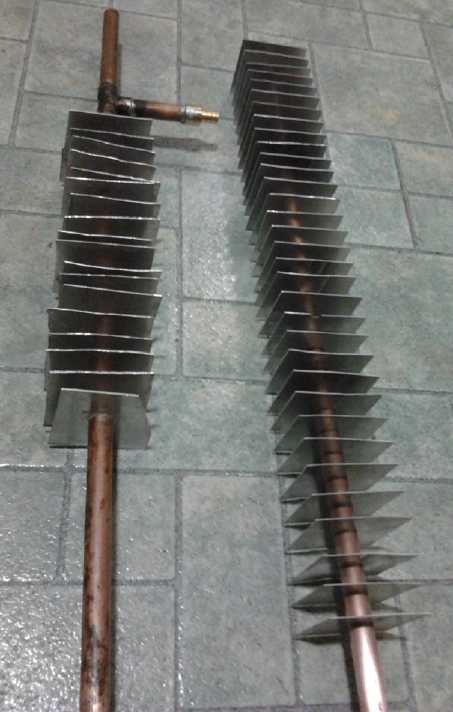
I got another
idea for the pipe heat/cold radiator fins:
Cut a bunch of pieces of aluminum sheet the desired fin size (~3" x
3"), then use the jeweller's 5/8" hole punch to punch an exactly
pipe-sized hole in the center of each piece. That seemed to work fairly
well for a rough trial, and I did a foot of pipe.
Another thought occurred to me before bed: TecTeg had done
a lot of work to make those aluminum channel blocks, and I was told
they each took about an hour's machining. I had replaced the aluminum
cover of one with copper to improve the heat flow. Heat rapidly
transferred to the water and the rest of the box had no special
requirement to heat or
cool.
Suitable boxes - in some respects better - could as easily be made on
the 3D printer out of plastic, in not so much more time. Cheap and
replicable. I'd definitely have only one pipe coming out each end, and
save considerable plumbing.
They'd still be given copper covers, and the heat or cold
would transfer 'instantly' across the copper between the peltier unit
and the water.
Of course, such materials are good only for low
temperature Peltier units, not for TEGs. For those the aluminum blocks
will be vital.
On the 28th, Jim Harrington of AGO Environmental
Electronics made a financial contribution to the project. At this time
of year I can use it! He also mentioned a nearby potential source of
surplus copper radiators. But the one I saw had narrow, back and forth
piping for pumped systems. It would fare poorly in thermosyphoning.
Maybe it'll want a small pump(s) anyway to minimize temperature gain
(and loss) in the water box(es) and keep the Peltier modules operating
at best efficiency... but not until I've tried with convection flow and
no moving parts!
I bought a mini sheet metal shear to cut fins with, made a
little template to get the holes centered, and later, on March 3rd, 3D
printed a couple of plastic clips to evenly space the fins.
Performance Tests
 Jim wanted me to measure the performance. I came up with a
quick plan: mount peltiers to identical aluminum blocks on the hot and
cold sides, take the room temperature, and measure the hot side and
cold side block temperatures as they changed, with various target
supply voltages on the peltiers. The temperature of the hot side is the
heat pumped plus the heat from the electrical power. While the hot side
gets hotter less than twice as fast as the cold side got colder, more
of its heat is from the heat pumping than from the electrical energy
supplied. When it drops to double the temperature change, that's the
average 200% COP point. Ideally both blocks would be insulated from the
room air to minimize radiative temperature change. Temperature change
should be slow enough that the temperature sensors would keep up with
it, suggesting a fair mass of aluminum.
Jim wanted me to measure the performance. I came up with a
quick plan: mount peltiers to identical aluminum blocks on the hot and
cold sides, take the room temperature, and measure the hot side and
cold side block temperatures as they changed, with various target
supply voltages on the peltiers. The temperature of the hot side is the
heat pumped plus the heat from the electrical power. While the hot side
gets hotter less than twice as fast as the cold side got colder, more
of its heat is from the heat pumping than from the electrical energy
supplied. When it drops to double the temperature change, that's the
average 200% COP point. Ideally both blocks would be insulated from the
room air to minimize radiative temperature change. Temperature change
should be slow enough that the temperature sensors would keep up with
it, suggesting a fair mass of aluminum.
I found a couple of irregular chunks of 3/8" aluminum
plate that weighed 454 & 453g. I figured that with just one peltier
at 8 volts, the temperature changes might be slow enough I could keep
up with them. On the first test I got such poor results that I tried it
again, and got the same thing. Then I realized that the aluminum plates
were so large that the warm plate had a large surface area one peltier
thickness from the cold, so that it was heating it up appreciably.
Aluminum cubes would have been better.
I may not have gotten the measurements I wanted, but it
was a good reminder that the hot and cold sides have to be as separate
as possible, and I came up with a couple of new points:
1. The copper or aluminum hot and cold plates should be only just large
enough to fit the peltiers and conduct their heat to the water. (Any
surplus metal "looking at" the other side should be insulated - as well
as possible with only 3mm thickness.)
2. Plastic water boxes might well be better than aluminum as they don't
transmit heat well. They'd be all plastic except for the heat
conductive metal faces the Peltier modules mount on. That means no
direct radiation of heat from the boxes, but also no radiation towards
each other or in proximity to each other. And clamping the two boxes
together with the peltiers in between could be done with metal screws
instead of nylon, as the temperature won't transmit through them.
Metal backs, perhaps with heat sink fins, could be
employed. I think I'd rather have solid plastic, providing fewer seams
that might leak. 1/2" copper pipe fittings, or plastic hose fittings,
and interior supports for the metal plate which would also stir up the
flow, would be 'molded' (printed) into the plastic part.
I cut out a peltier square hole in a thin piece of foamy
packaging material and stuck it in between the plates. I tried at just
6 volts, but that just gave more time for heat transmission between the
plates. I started to think that if I had to go to a lot of trouble to
make a test rig, I might just as well do the real thing. And point 1
above suggested that since 8 peltier modules would fit on the TecTeg
plates, I should fit 8 instead of 6. Less extra to need insulation.
 That should
have been it for the month, but on March 3rd, having been distracted
from finishing this newsletter by various things on the 2nd, I awoke
with the rather ambitious idea that I should test the 200% performance
idea and put the results in this newsletter.
That should
have been it for the month, but on March 3rd, having been distracted
from finishing this newsletter by various things on the 2nd, I awoke
with the rather ambitious idea that I should test the 200% performance
idea and put the results in this newsletter.
I thought the best way to
do that might be to build and install the whole heat pump unit, and
compare performance with a 400 watt electric radiant heater. I had
decided to do the 3D printed plastic
boxes with copper sheet/plate faces. I spent the morning cutting
aluminum fins
and putting them on copper pipes, then fitting the pipes up. I 3D
printed two plastic spacer clips to space the fins evenly.
In the
afternoon I started designing the boxes. Naturally it took quite a
while; pretty much the afternoon. To my surprise, they turned
out to be too long for the 3D printer's 200mm maximum size, so I re-did
them a little shorter. They would also be 2-1/2 hour prints. But I'd
been having trouble with the temperature readings from the extruder,
and I tried to tighten the connections. I had nothing but trouble with
the printer after that, and finally gave up at 10 PM with the plastic
not sticking to the glass and smoke coming
out the extruder nozzle, which must have been considerably hotter than
the reading on the computer.

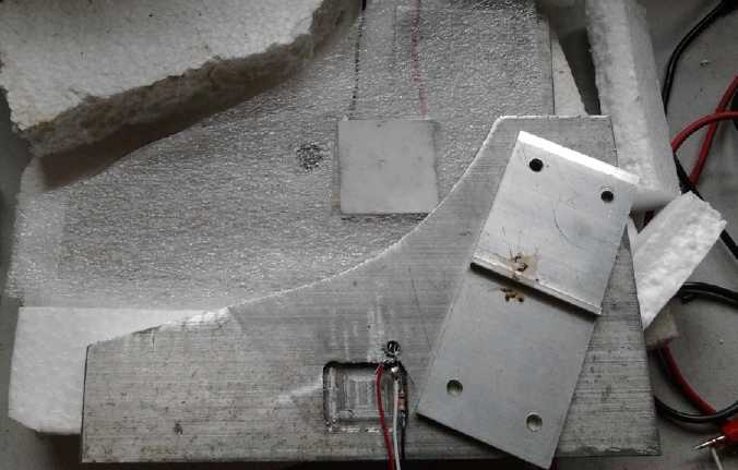
Parts for test #2 on March 4th.
Top: clamp
Left: one of the lids and plates
Right: the other plate with peltier & cardboard insulator on top,
lid under.
I "discovered" that
water expands as it's heated when a little water came out the warm
side hole after the first test, and on a test I continued to
50ºC, there was a small puddle underneath, and not enough water
inside to reach the sensor (in the top hole in the edge of the jar lid
during that test) after it cooled. (I
allowed for expansion in the heat pump radiator pipes.)
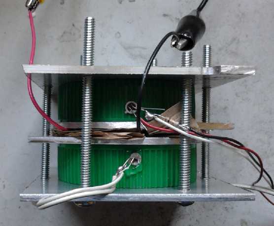
Assembled tester in use. Temperature probes are in the water filler
holes in the jar lids.
The lids were filled with a syringe with about 65cc of water.
| Volts |
Elapsed Time
(seconds, approx) |
Amps |
Hot Side ºK
(º read at aluminum
Peltier face plates)
|
Cold Side ºK |
Hot, Cold, COP |
| 8.0 |
0 |
0 -> 5 |
290 |
289.5 |
|
| 8.0 |
20 |
3.3 |
299 |
287 |
+9, -2.5, 138%
|
| 8.0 |
40 |
3.2 |
304
|
285
|
+5, -2, 167%
|
| 8.0 |
60 |
3.1 |
306
|
284.7
|
+2, -.3, 118%
|
| 8.0 |
80 |
3.1 |
307
|
284.3
|
+1, -.4, 167%
|
I took more readings, but the cold side stopped getting colder and the
hot side rose slowly. There's heating and cooling the aluminum plates,
and then there's heating and cooling the water behind the plates, and
then there's the caps radiating back to room temperature. Measuring in
the water showed little change in the cold side and huge change in the
hot side. You'd have never guessed the module would freeze water.
I decided to try again, at 6 volts, measuring temperature at the plates
again. This is the voltage the Peltiers of the fridge will have if two
are in series with the 12V supply.
| Volts |
Elapsed Time
(seconds, approx) |
Amps |
Hot Side ºK
|
Cold Side ºK |
Hot, Cold, COP |
| 6.0 |
0 |
0 -> 3+
|
302
|
301.4
|
|
| 6.0 |
20 |
2.3 |
307
|
299.2
|
+5, -2.2, 178%
|
| 6.0 |
40 |
2.2 |
310
|
297.3
|
+3, -1.9, 273%
|
| 6.0 |
60 |
2.1 |
312
|
295.7
|
+2, -1.4, 233%
|
| 6.0 |
80 |
2.1 |
313
|
295.3
|
+1, -.4, 167%
|
And then at 7.5 volts (which I might use for the heat pump), trying to
get readings a little closer together - every 15 seconds.
| Volts |
Elapsed Time
(seconds, approx) |
Amps |
Hot Side ºK
|
Cold Side ºK |
Hot, Cold, COP |
| 9.0 |
0 |
0 -> 4+
|
293
|
292.4
|
|
| 9.0 |
15
|
2.9
|
298
|
290.7
|
+5, -1.7, 152%
|
| 9.0 |
30 |
2.8 |
304
|
288.6
|
+6, 2.1, 154%
|
| 9.0 |
45
|
|
307
|
287.5
|
3, 1.1, 158%
|
| 9.0 |
60 |
32.8
|
308
|
287.2
|
1, .3, 143%
|
And finally at 9 volts.
| Volts |
Elapsed Time
(seconds, approx) |
Amps |
Hot Side ºK
|
Cold Side ºK |
Hot, Cold, COP |
| 9.0 |
0 |
0 -> 5+
|
296
|
295.4
|
|
| 9.0 |
15
|
|
303
|
293.7
|
+7, -1.7, 132%
|
| 9.0 |
30 |
3.6 |
310
|
291.2
|
+7, -2.5, 156%
|
| 9.0 |
45
|
|
312
|
290.4
|
+2, -.8, 167%
|
| 9.0 |
60 |
3.5
|
314
|
290.0
|
+2, -.4, 125%
|
The test and the readings are rough, eg, "2 degrees"
change
with no fractional reading results in quite a different COP figure
than "3 degrees" and depends on just which way the meter flipped at
the time of reading. The results appear to
be somewhat skewed in the adverse direction by slow temperature probe
response - and probably poor thermal contacts in the test setup - since
in every case the first COP calculation, which
should be highest, is lower than the second one, and they're mostly
somewhat lower than the datasheets indicate.
It takes several seconds after turning the power on before
the readings start to change, and 10 or more seconds before they stop
going further after turning the power off. The Peltier modules
themselves take under a second to change quite a lot - that can be felt
with the fingers. Poor thermal connection between the Peltier module
and the plates would definitely skew the results for the worse, and as
didn't think to use heat conductive grease, poorer connection is quite
likely.
Ideally temperature would be measured on the Peltier module itself, but
this
would be difficult.
I tried a different digital
thermometer to get
readings with a decimal point on the warm side, but its heavier probe
responded more
slowly
than the small AD590 chips, and it was touching but not making very
solid connection to the
plate. The resulting COP figures looked awesome - a couple were even
impossible! This
illustrates how little it takes to skew the results.
But even the overly conservative results above from the
'rough
and ready' test setup show the essential idea that Peltier
modules driven with lower than usual
power can give a good coefficient of performance as a space heating
heat pump. The rather hidden trend of "the lower the power
input the
higher the COP", and the better known one of "the less the temperature
difference, the higher the COP", are evident. "Poor thermal transfer
reduces the COP significantly" is another (not unexpected) finding to
bear in mind for
building real units. That the 200% COP indicated (if somewhat
obscurely) in the CUI Peltier module datasheet graphs is attainable, is
at least hinted at.
Someone else did an experiment in 2009 with the thought of
home heating in mind, to see how much energy it took to raise 100cc of
water by 24.5ºC. He calculated a COP of about 2.6.
[ www.youtube.com/watch?v=_XXHwodTc5E
] He was running the Peltier at a higher voltage and current than gives
best efficiency, however his average temperature differential (at least
in the water) would
have only been 12.25º.
Electricity Generation
Wood Stove (heat source) Thermo-Electric Generator Project
This story is a chronology of how the design developed
from initial flawed concepts to 'planned in considerable detail' over
the
month. At first the numbers led me to be inclined to drop the whole
idea as having too little electrical output for too much money. But I
studied it further, learned a lot, and improving design ideas came to
me.
One great design idea came from a friend who had worked
in solar energy development many years ago.
I believe I now have a better plan than the maker of the
TEG modules I've bought to make it with has, since I'm not getting
their woodstove TEGs at all, but some others that make more electricity
at a substantially lower temperature - and are also less than half the
price. Part of the insight comes from years of experience with burning
wood (carbon neutral and renewable!) - and with having a surface
thermometer fortuitously bought decades ago, always sitting on top of
the stove. There's how hot it can get, but then there's also
the much lower temperatures it normally operates at. Like an ocean wave
power, the unit needs to be able to survive the extremes, but
performance will be disappointing unless it's sized to get power from
typical conditions.
First idea: Peltier elements can make electricity? Wow!
I bought a new wood stove, said to use less wood and burn
cleaner than my old one, and I thought I'd get one of
those little Caframo "Eco-fans" that runs off the heat of the stove to
blow the heat
around the room. I knew they used
"thermocouples" to generate electricity, but I guess I'd never taken a
close look. When I sat down I was at the right height to see a familiar
looking form: the edge of a peltier element, which separated the upper
heatsink fins and the lower aluminum block that carried heat from the
stove surface. I undid a screw and looked, but the element was dark
silver on both sides with no part
number. (Gluing thin copper or aluminum to the Peltier element seemed
like a
great idea to improve heat transfer! I found out later it's probably
graphite, which is evidently a good heat conductor.)
I'd never given this any thought before - I hadn't
realized Peltier elements might be effective for making electricity
from temperature differences instead of the other way around. But how
practical
would it be to make a Peltier array specifically to generate
electricity? Well, any waste heat would come off the stove and peltier
array
as was happening anyway - the intended effect of burning wood. So the
only energy that wouldn't come out into the room as heat would be that
taken away as electric power. In effect, it would be "100% efficient".
The stove would make the same heat with extra wood only to the exact
extant as was removed in actual electrical power. (If that. And I'm not
sure that'd
even be noticeable below at least a few hundred watts.) That means the
only consideration concerning efficiency and effectiveness would be the
number of Peltier elements required for a given amount of electricity,
and hence the cost of the generator per watt.
The stove was just warm with a near dead fire. The surface
thermometer said 150ºF. I brought down an 8.4 amp peltier element,
a small bar of aluminum as a temporary heat sink to keep the top side
cool long enough to test it,
and some things from the battery lab. The peltier element went up to
about .8 volts, including with a 10 ohm resistor attached. With 5 ohms,
the voltage dropped to .4. The 10 ohm reading seemed to indicate around
.064 watts. Small
peanuts, but then it was one element and not much heat. What would it
do at 300, 400 or 500ºF, with the effect multiplied by "n" peltier
elements?
As the possibilities started occurring to me, one idea was
to
check on the web and see what others had done rather than duplicate
other peoples' work. After all, this was hardly rocket science. But I
found surprisingly little solid info or products beyond fans like I'd
just bought, a generator unit for sale with no explanation of the
workings, and experiments like powering a low power radio - not so far
beyond my quick test. Later I found more, but by then I was enthused
about a seemingly unresearched area, and did have an idea or two that I
didn't see elsewhere.
Getting back to actual ideas, I had five 8.5 amp Peltiers
still
in the drawer. If these were placed in series, they'd probably generate
well over 18 volts with good stove temperatures, which could run its
own DC
to DC down converter and charge controller. Then I had the thought that
it could simply be diode
isolated as a source, as if it were just another solar collector, into
the regular
solar PV system DC to DC converter/charge controller. Thus it would
need nothing extra to tie it in - just the unit itself, a fuse, a
diode, and some wire. They'd be a
perfect complement to solar panels in the PNW climate, generating
electricity pretty much
at the opposite times of the panels.
The next question was
whether they'd produce enough power to be worth doing. A solar panel is
presently around 500$ and makes over
200 watts if the sun is out. That's 2.5$/watt. The elements draw 8.5
amps at about 14 volts (~120 watts) to create temperature differences.
If they're 10$ and make
even 10 or 15 watts with a good fire going, then the active elements
would
be substantially cheaper than collectors.
20 Peltier elements in series and or parallel could fit
along one edge on top of the woodstove, with the cool side heatsinks
draped over the side, perhaps assisted by a small (self powered) fan.
It could just hang there, or be "C-clamped" on. Or they could be placed
on the side of the woodstove if it isn't obscured by a side baffle
plate. (Until yesterday I had a woodstove with no side baffle... arhg!)
They make 200 to 300 watts of electricity with a good fire on. (I might
consider some sort of bimetallic system to decouple the hot side from
the stove if
it gets too hot.)
The cost would be the price of the elements (200$?) plus
all the aluminum heatsinks and stuff... and the fan... and the wiring
to attach it to the 12VDC power system of the house.
The construction would in fact be very similar to the
Peltier Element Heat Pump detailed 2 or 3 TE Newletters back. They
could probably be wholesaled both to solar and woodstove places, or
sold direct.
Later on I came in after having added some more wood, and
the stove top was up to 450ºF. I tried it again and got as much as
2 volts into a 1.5 ohm load, almost 3 watts. Yay! On the next try...
nothing
worked. Apparently I'd burned out the peltier element. Oh ya,
450ºF is hot enough to melt solder. Here was a definite
problem with the idea.
Thermo-Electric Generators (TEGs)
So... the fan had to be using some high temperature
version of a Peltier element. A quick web search found the answer: yes,
there are special high temperature ones. They look much the same, but
they're optimized for power generation, the "Seebeck" effect rather
than their "Peltier"
cooling/heating effect effect. They're called Thermo Electric
Generators - TEGs.
Of course I'd heard of "RTGs" or "RTEGs" that have powered
spacecraft from a piece of hot plutonium in the outer solar system
where solar energy is feeble since Pioneer 10 and 11 first went to
Jupiter and Saturn. But I had no idea that such things were made in a
practical form and available for purchase.
(EBay)
"
Thermal
Enterprises model HT1-12710.
High Temperature 40mm TEG, Sealed for moisture protection
- Thermal Elements formulated for optimum Seebeck (Power
Generation)
- Constructed for higher operating temperatures (230 deg C maximum
exposure)
- Teflon insulated lead wires for use in higher temperature
applications
These modules are manufactured specifically for high temperature
applications such as
power generation. Although they can also be used for cooling
and/or heating applications, they are far superior than standard
peltiers for
power generation applications. They can be safely operated at much
higher temperatures that standard peltier devices are capable of
withstanding. Each module contains 127 junctions and 254 thermal
elements that are formulated for optimum Seebeck. Unique
construction
includes the use of high temperature solder (238 deg C) and Teflon
insulated lead wires for high temperature operation.
Standard peltier devices are typically limited to a maximum operating
temperature of only 150 deg C which limits their use for power
generation. These modules can be exposed to temperatures as high as
230 deg C and can be operated continuously at 200 deg C making them
ideal for power generation use.
"
A visit to a web site or two was rather disheartening.
There were
some, but the prices were about 10$/watt of maximum capacity, and the
watts per unit per
temperature were lower than I expected. Perhaps I'd order a few of
these at some point and try
things out, perhaps not. But not today!
Woodstove observations suggest cheaper, lower temperature TEG
selection
Then I exchanged some e-mails with a TEG vendor in
Ontario, TECTEG.com,
and
also watched the stovetop temperatures on my new woodstove for a few
days,
which led to an improved idea. I found that typically the stovetop was
150-250ºc, and most commonly under 200º. The vendor had some
190ºC rated TEGs that were less than 1/2 the price of their
320º
units, and which made the most electricity at my stove's typical
temperatures, giving an effective price of around 5$/watt.
He further said that owing to the large heat transfer
from the hot
side to the cold side, the stovetop temperature under the unit could be
cooler by as much as 100º. Thus the
320º units, tho intended for woodstoves, would actually have quite
low
output except when there was a very hot fire, which would be rarely,
and might effectively work out to 25$/watt and very disappointing
average power
output. This seemed to be the case, as the couple of existing units I
found
on the web were rated at 50 watts or less - and probably produced much
less on average.
On the other hand, the
190º units could easily be burned out if there was a too-hot fire.
They'd only need to be burned out once to ruin an expensive
thermoelectric
generator - who would pay to replace them knowing they would,
inevitably, eventually be burned out again?
Here's some data from the manufacturer:
"TEG 2.0" CONSTRUCTION SPECIFICATION:
1. SnSb 240°C based solder hot and cold side.
2. Ceramic slit for multi thermal cycling applications both hot side
and cold side ceramic. [ie, long lasting with heating and cooling]
3. Lapped [all the same thickness] for multiple modules on the same
surface.
4. Teflon insulated on the lead wires.
5. Lead wire contacts are attached to cold side for extra protection.
6. Offered in Graphite cover (eliminates thermal grease requirements)
or standard Ceramic
MPPT Power ratings at various
DT
| DT Celsius |
Voltage Match |
Current Match |
Watts Maximum |
| 50 |
.6 |
1.4 |
.84 |
| 80 |
1.0 |
2.5 |
2.50 |
| 100 |
1.3 |
3.0 |
3.9 |
| 120 |
1.6 |
4 |
6.4 |
| 150 |
1.9 |
4.2 |
7.98 |
| 170 |
2.2 |
4.4 |
9.68 |
| 180 |
2.35 |
4.5 |
10.6 |
EXAMPLE: @100°C DT. Hot side
150°C- cold side 50°C
-The open circuit = 2.6V
-The matched load output voltage = 1.3V
- Internal resistance = 0.5 Ohm.
- Matched load current is matched load output
voltage/Internal resistance.
- Heat flux ~140 watt [This is the transfer of heat from the hot
side to the cold side to make the 3.9 watts of electricity.]
On the 15th I ordered a 'liquid thermoelectric module'
which had 16 of the 190º TEGs and three thick aluminum plates each
with two pipes running through, and also two 5x5" heatsinks with
closely spaced 2.3" fins, to keep the cold sides cool. (I had been
looking for such heatsinks for Peltier fridges.) I figured that if the
stove is too hot, blowing air through the pipes (perhaps by chimney
effect) could keep the top of the plate within specs for the hot side
of
the 190º TEGs. If one plate couldn't be kept cool enough, I can
put
two on, one on top of the other, or even all three.
If it worked with one plate, I'd be able to mount all 16
TEGs on two plates and have a unit that generates perhaps 40 to 120
watts as long as the stove is running. A woodstove TEG system will run
essentially all
winter. It won't stop at night like a solar collector (but will slow
down substantially
with the typical low night fire), so battery storage need is minimal.
In Victoria BC solar collectors are rated for 1000 hours/year. The
woodstove probably runs 3000-4000 hours/year, so the price per watt of
capacity needs to be divided by 3 or 4 to compare the price per
watt-hour of electricity generated.
If two or all three plates were required under just 8
TEGs, I'd have to buy or make more of them to hold the rest.
Liquid cooling tubes instead of air, heatsinks and fans.
On the 17th I started thinking maybe liquid in the tubes
would be better after all. It's pretty pricey per watt anyway, so it
would be worth going to some extra trouble to increase the output. If
the cold side could be kept cooler, for example at 30ºC instead of
50, the output would be higher per the table above. The maximum
[190º-30º=160º] would be about 8.5 watts per TEG instead
of [190º-50º=140º] about 7.5. (Ice water going through
the cold side pipes could make it over 10 watts.)
For the cold side, if a standard copper pipe radiator with
aluminum fins were situated away from the stove's heat and above the
level of the unit, water would circulate by natural convection, and
enough pipe would bring the water down almost to room temperature by
the time it returned to the stove.
For the hot side, water could be admitted from a container
whenever necessary to keep the hot side temperature within safe limits.
This would boil, and the steam would return up the pipe to the
container.
Suddenly, it looked fortuitous that I had ordered the
liquid plates TEG assembly! But it seemed it would need a fourth plate.
I called and got the order changed before it was sent.
2 of the 4 water plates as they're mounted (shown with 6 Peltiers
instead of 8 TEGs).
The bottom of the hot side will sit on the woodstove.
Evacuated & Pressurized Pipes for 'Instant' Heat Transfer
On the 21st, a
friend who had once worked in the solar industry told me how to make an
evacuated copper pipe with a bit of water in it. Evidently
if the bottom of the pipe is heated, the instant steam instantly
distributes the
heat throughout the pipe, thousands of times faster
than through copper or aluminum. Evidently the one tricky point for
higher temperature use is to use an amount of water under where the
pipe would burst if it all boils, which amount would (will) have to be
calculated, yet still have a reservoir of liquid at the highest
normal operating temperature.
Notwithstanding that it's evidently 400 years old, the
idea is revolutionary. It would make a fantastic way to remove heat
from the cold side of the TEGs and get the maximum electricity out of
them.
The technique to make the evacuated pipe is first to crimp
and seal (solder) one end, then to put in the water, then to crimp the
main pipe to fit and solder on a thin soft copper tube at the top end.
Put the torch back at the bottom end and heat it until the water starts
to boil. The steam drives out most of the air. Crimp the thin pipe at
the top and bend it over (visegrips?) to seal it for the moment, then
solder it shut securely. Use silver solder if it's for high temperature
use. (I suppose 1/2" soft copper pipe could be crimped shut without
troubling to add a thinner soft copper tube on the top-?)
Making an evacuated heat transfer tube sounded much
simpler and
more effective than I had imagined! In fact, I never understood much
about them before. But a couple of attempts didn't quite work.
Evidently they weren't steaming hard enough when I crimped the end. I
didn't get around to trying again.
In a working pipe, just enough water will remain as steam
to create the
equilibrium vapour pressure that will prevent more water from boiling
off. This pressure varies with temperature, so if the water temperature
rises, more water will turn to steam, and steam is about the best heat
transfer medium known, so the entire pipe is heated pretty much equally
even tho the water being heated is at the bottom.
Furthermore, consideration of this gave me another idea. I
had thought of boiling water to keep the hot side of the TEGs from
overheating. But normally water would boil at 100ºC, which is much
cooler than the desired 190ºC. Entry of the water would have to be
carefully controlled.
But water under pressure boils at a higher temperature. If
the TEG hot side plates were connected to a tube with a bit of water
that was pressurized to boil at 190ºC, the maximum
permissible temperature of the TEGs, the steam could almost instantly
carry off the excess heat to a heatsink away from the stove. No control
besides the correct pressure would be required. With a too-hot stove,
it should be possible to safely extract electricity right at the
maximum TEG temperature without worry that they would ever get too hot
and burn out. This idea is probably even more valuable than the
evacuated pipes.
The technique to make the pressurized pipe is a bit
different: Make the pipe with a valve like a tire filler valve (and
good for high temperatures). Add the water. An air compressor can be
used to pressurize the pipe and a tire pressure gauge can read the
pressure.
With the cold side reduced to near room temperature
(20º) and the hot side regulated to 190º, the maximum output
of the unit, attained whenever a good fire is on, rises to about 9
watts per TEG for a total of about 144 watts. Now we're talking power!
That's almost three times the typical 50 watt ratings I've seen so far,
and those units probably only make the 50 with very hot fires on.
Notwithstanding research and tentative development work by
a number of people, I have the
impression that this really is a new product development area. The
designer has
plainly done a lot of meticulous R &
D, a labour of love with no net return so far, to come up with good
products. The TEGs
are all lapped to exactly the same
thickness and the liquid plates are machined to exact flatness,
ensuring good contact of multiple TEGs between two plates, and the
plate liquid channels are made to maximize flow and heat transfer with
minimal pressure, which is ideal for the thermosiphoning flow.
Also of note, the same designer has in the past made
Peltier element fridges for solar use in Africa. From his description,
they were remarkably similar to mine, even to the ice compartment. The
only notable differences were that they had 4" of foam insulation
instead of 3", and had a thermostatic fan inside to spread the coolness
from the ice compartment. (Mine, relying on drift of the air, is much
cooler at the bottom at the ice end - 1 to 4ºc - than at the top
at the far end - 8 to 10ºc. I've thought of adding a fan, but
haven't bothered so far.)
I'm so glad my friend knew of the evacuated pipes and how
to make them, and shared his know-how with me!
Quick Experiment
The TEG with water plates and a finned heatsink arrived on
the 26th. On the evening of the 28th I took one of the TEGs, the
heatsink, a voltmeter, aligator clip leeds and some resistors down to
the woodstove. I wasn't very methodical and when I got down to the
lowest resistance value the tests following were all with that value,
.11Ω.
The stovetop started about 130ºC. If the heatsink was
25 or 30, that meant about 100º temperature differential. For each
test, I put the TEG on the stove and pressed the heatsink on top, and I
didn't
go much longer than needed to get a stable reading. At one point, I ran
cold water over the heatsink to get it cold again. If the pressure
on top wasn't even, the output dropped. The readings below were the
maximums.
The first time, open circuit voltage went to over 1 volt,
even 1.2. Then I put a 1 ohm resistor across the output, and still got
about a volt. That would be one watt. I then tried .5 ohms. It was
still almost a volt - 2 watts. I tried .22 ohms. I can't remember the
exact voltage, but it was only down a little way. It seemed to me to be
the best reading, maybe about 3 to 4 watts. Then I tried .11 ohms and
read about .5 volts - 2.25 watts. The stove temperature was gradually
dropping, and the reduced output started to become noticable. Also, as
the manufacturer had said, the areas where the TEG had been sitting did
seem to be cooler than fresh areas. The next time, .11 ohms was down to
about .45 volts, and soon I could only get .4, which is 1.5 watts. And
the temperature was down to 110ºC, for maybe 80º differential.
Checking the results against the chart above. Max for
100º says 3.9W and for 80º, 2.5W. The .22 ohms test was
around the first figure, but the others with the .11 ohms were under
max. Apparently I should have stuck with the .22 ohms and perhaps tried
some finer adjustments near that figure.
The essential conclusions are (1) that the TEGs seem to
work pretty much per the datasheet as far as was observable, and (2)
that they do indeed cool off the stove top. These ones probably cool it
less than the ones intended for woodstoves. Even so, this might lead to
lower than expected outputs,
and a larger bottom aluminum plate might be useful to gather heat from
a
larger stove surface area. I almost think the stovetop won't
get above the TEG maximum rating of 190º... but again, you only
have to burn them out once to ruin them, and they're costly.
Steam Turbine with Evacuated Tubes?
A further idea for use of vacuums with steam has occurred
to me a
number of times. We're used to needing 100ºC to boil water, and
sometimes, eg with a solar hot water collector, "low grade" heat can be
collected that doesn't hit 100. But it could still be boiled in
a partial or near complete vacuum. Then the steam created could be used
for the sort of things that steam is normally
used for, such as running a turbine, albeit probably not a very
powerful one.
One thought for this is for harnessing geothermal energy
that's not quite up to 100ºC. Dry oil wells sometimes find such
levels of heat underground - and occasionally even steaming
temperatures - and if there was any co-operation between fields, we
could probably be using cheap geothermal electricity even without
spending the money to drill wells specifically for the purpose. The oil
companies just close them up when they don't find oil, or when the oil
runs out, even if they have evident geothermal potential.
River & Stream Hydro with Surface Water Wheels
Someone is interested in my still unfinished Electric
Weel motor as a 10KW low RPM generator for hydro power. This sounds
like
a great project! Then somehow I
started looking at wind power machines on youtube, and found a company
in Belgium claiming to make the world's best vertical axis ("Eolienne")
wind power machines, which also had shallow draft water wheels for
electric power generation from small
streams. http://www.greenenergyresearch.eu
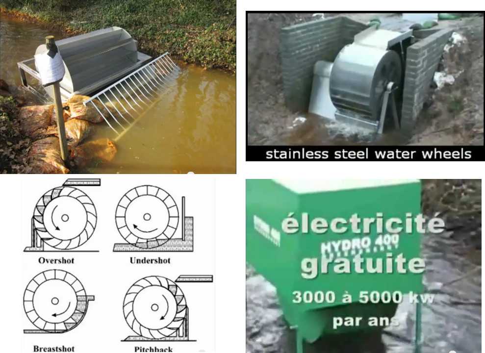
I'm particularly intrigued by the 'undershot'
wheels, which work in just a few centimeters of fast flowing water,
evidently off
its velocity without requiring much head.
Another company had floating turbine units
that would be anchored in a river. (no pictures) These would doubtless
be for
deeper rivers. Imagine a bunch of these up and down the Peace river
instead of the Site C dam! How could they cost as much? and they
wouldn't flood a huge tract of land.
These types of things are attractive for being little
disturbing to the stream and easily movable or removable if problems
are found or if the stream bed changes.
Electricity Storage - Turquoise Battery Project (etc.)
Self Discharge - Electrolyte Impurities? Crud?
The first 'production prototype' cell seemed to
have high self discharge. and considerable bubbling of gas. But why? I
thought I had done everything
right. And I was sure I'd had manganese metal holding its charge in a
couple of test cells before. Suddenly on the 4th I had the thought that
perhaps
the pottery supply MnO2 I'd used had some critical impurity, something
that had too low a hydrogen overvoltage and would generate hydrogen.
This began to clarify things... with
the high negative reaction voltage of manganese, it could be almost
any conductive or semiconductive impurity... except zinc or a few
select transition metals like antimony, lead or bismuth. It would have
to be
pure to hold its charge for the same reason the current collector and
conductivity additive can only be zinc.
Some impurities might possibly be burned out in the kiln,
but I decided to put together a second cell (which I'd already started)
and use only
micronmetals.com Mn metal powder in the negode. Being a coarser powder
than nano-oxides, it seemed to have quite low amp-hours per weight when
I tried it before, but perhaps if I torched it to oxidize it some, it
would be improved.
Then it occurred to me it might be contaminated
electrolyte, or a bridge of powder in the top area between electrodes.
That was easily checked. I shook out the electrolyte (it doesn't really
pour through the tiny filler hole) and some solid electrode particles
came out as well as purple water. I gave it another rinse or two,
filling and shaking. By the end, more purple, but not much particles. I
refilled with KCl solution. When I hooked up the meter, the voltage was
slowly rising instead of falling, and it seemed to hold a charge.
Holding of its charge didn't seem to improve the pathetic
current drive or milliamp-hours capacity much. (pH seemed to be around
9 to 11.) The chemistry may work, but something in there still needs a
big improvement. I know the conductivity of the negode powder started
out
poor. "Production prototype" cell #2 would have to show big improvement.
Cell #1 autopsy
On the 28th, after using cell #2 since the 12th, I pried
open #1. The negode had hardened up nicely. The most striking thing was
that only the lower 1/3 of the electrode seemed to be in contact with
the zinc sheet. That would certainly do nothing for conductivity! Other
'features' were that the zinc sheet was corroded around the edges, and
that the posode seemed to have lost some material out the top, which
may have shorted and caused some problems. I've taken steps in the case
design to prevent this with future cells. I'm not sure whether the zinc
was initial charge corrosion or ongoing. I'll have to inspect more
cells at some later date. Maybe lead or bismuth current collectors (see
below) would be worth a try after all.
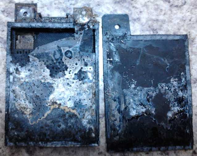
Some zinc corrosion behind zinc plate
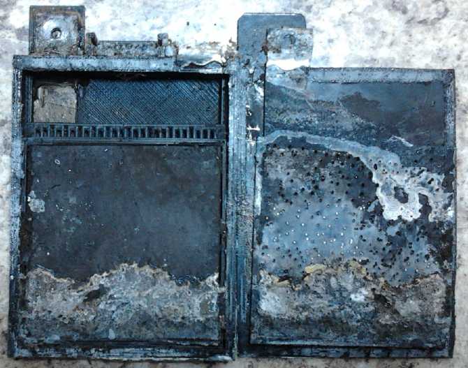
Looks like the zinc only contacted the Mn negode on about the bottom
1/3!
So essentially, only 1/3 of the battery was working.
I suspect cell #2 is no better.
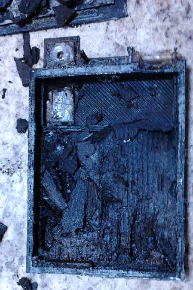
The posode. Not much left of the separator paper?
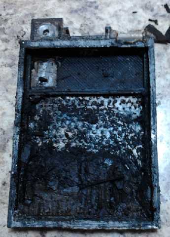
Bottom graphite collector with some of the posode pried away.
Seems there was pretty good contact.
Lead & Bismuth: other possible current collectors besides Zinc
I've said the current collector for Mn negodes can only be
zinc as nothing else has a high enough hydrogen overvoltage and would
bubble hydrogen and discharge the electrode.
On going over the [pH 14 alkaline] overvoltages list
again, I note that lead has a slightly higher hydrogen overvoltage than
zinc (1.35 vs 1.3), and a much lower alkaline reaction voltage (-.56 vs
-1.25).
This means that lead foil could be a good current collector for either
a manganese or a zinc electrode. However, either one seems quite
acceptable, and zinc is lighter and a "green" ingredient.
Given the present regulatory vendetta against anything
with the slightest bit of lead in it (except of course for the elephant
among the ants: short life, "nothin' but lead!" lead-acid batteries),
I'll avoid lead. Someone else can try it later and see if it has any
advantages.
Then, without knowing the overvoltage of bismuth, I recall
Bi2S3 has been used to raise overvoltage, so I would presume it's high
enough, and the reaction voltage (@pH 14) is under 1/2 a volt, so I
would think it would work. Zinc is doubtless cheaper.
Zinc as an electrode material - still trouble?
I did a bit more reading on zinc as an active
electrode
material (as opposed to current collector). It was intriguing that it
didn't seem it would form soluble
zincate ions in a less alkaline solution, suggesting that it probably
wouldn't form dendrites and might have long or even endless cycle life.
But there were things mentioned in a patent I read going over various
problems of
zinc, not limited to dendrite formation, such as areas of electrode
passivation and beta versus non-conducting gamma forms of the oxide. It
sounded
daunting - maybe a bit like lead-acid - and I'll probably steer clear
of zinc. The problems
discussed - or some of them - just might also be remedied by a lower
pH, but I'll leave it to someone else to try out.
Another problem I thought zinc had was that there didn't
seem to be
a good metal to make the current collector from. Most metals don't have
a high enough hydrogen overvoltage and will cause self discharge, while
those that do have higher reaction voltages than zinc and hence won't
stay in metallic form in the electrode. However, I missed lead and
bismuth, which should remain in metallic form until the
cell was virtually dead, and even then would probably recharge fine.
Compaction Good. Dropping electrode
on floor Bad.
For the negode for 'production prototype cell #2', I used the same mix
as before:
- 25g/50% MnO2 (from a new bag - still from pottery supply)
- 15g/30% Mn power, #300 mesh (MicronMetals.com)
- 10g/20% Zn flake powder (eBay)
- .65g/1+% Sb2S3 (American Pyro Supply iirc)
I used Sunlight dish soap, and distilled water this time
(purity, purity!), to wet it down. It looked about the same as last
time and again took about 35 grams of powder, but last time it measured
around 100kΩ resistance between any two points. This time I evidently
attained better compaction. Near the bottom it was hard to compress
(the die was too short to reach the bottom), and it measured around
60KΩ. Higher up however, I'd worked it down a bit harder and it was
about 6KΩ - an order of magnitude more conductive. Up near the top I
tried to squeeze in as much powder as I could and it was just 2.6K. I
decided to make a new die and squeeze it harder next time.
I put the 'trode (still on a piece of the stainless steel
compactor) in the oven on a fire brick to drive out moisture, carried
it out to the garage and torched it, carried it back up to the lab, and
tried to set it on a hot plate burner to cool, since it was quite hot.
But I tilted it a bit and the polished stainless steel slid off the
firebrick, over the edge of the counter, and smashed on the floor. The
torched pieces had resistances in the mid ones of megohms, since I'd
oxidized the zinc and the manganese powders to semiconductors. (The
zinc would have also been "calcined", converting any that had turned to
carbonate [ZnCO3, as zinc gradually does] back into oxide [ZnO + CO2].)
Of course these high resistances should have dropped back down as the
cell charged and reduced them to metallic state again.
So that "next time" came sooner than I thought, and I used
padded work gloves instead of clumsy oven mitts to handle the hot
piece. But first I found a longer piece of stainless plate of the right
thickness for a compactor die. I definitely wanted those far lower
internal resistances that come with higher compaction, and throughout
the electrode. With the compactor making groaning noises at the end of
each pressing, I succeeded. There were a few readings around 12KΩ, but
mostly they were down around 4K or 5K between any two points.
Regardless, this briquette too weighed almost exactly 35 grams, and I
put it into the cell.
The zinc flake powder is a very fine dust. Making the plus
side, one gets graphite blackening everything. and potassium
permanganate turning every drop of water purple. With the minus, the
zinc makes the added water look like mercury and imparts a silver-gray
sheen to everything around. I'm glad I'm not using lead powder.
Filler hole cover balls
I took the ball bearing off "production prototype #1" and
found it had some corroded areas. It seems almost as if there's a
coating, perhaps chrome, and once it's through that the steel corrodes.
On the bright side, since I made the cells thicker (12mm), the 10mm
glass 'floral arrangement' decorative marbles can (just) fit in again.
So I decided to switch to those. At the end of the month I thought of
putting in a rubber "O" ring. That'll be great! - a good seal without
needing
a rubber coating on the balls, so the glass balls are fine.
Finally I glued the face onto cell #2. This time, I took
two plates of metal and four C-clamps, and clamped it together while
the
solvent evaporated and the the plastic hardened. This seems to be a
good technique, because for once the cell had no leaks.
Testing Cell #2
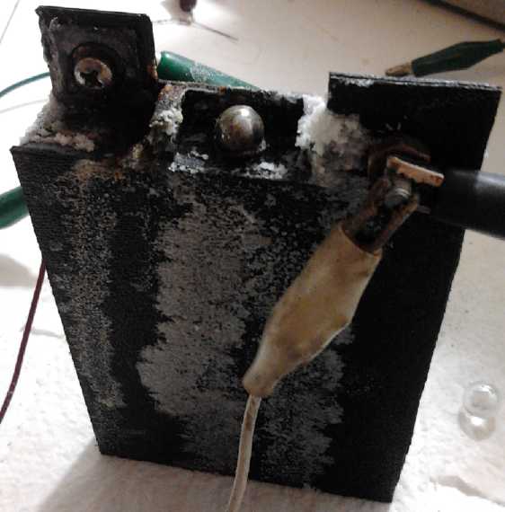
At first the performance seemed pathetic, and if one
tried to charge it very hard, it bubbled and suds came oozing out the
filler hole. Over a period of days I started trying more things. If it
boiled dry, I would just refill it. I started finding that it charged
not to the expected 2.2 or 2.3 volts, but to about 2.6, explaining why
charging
with 2.5 hadn't been working very well. It took almost 3 volts, or even
more. It
started
to hold voltage longer when I started discharging, but I did few long
period discharge tests. It still lost a lot of charge overnight, but
the morning voltages gradually rose from 1.7 to 2.2.
Current capacity was poor. 46-40mA discharging with 50Ω
was about as much load as it wanted. With 10 ohms it dropped way under
2 volts, eg, to 1.6,
supplying just 165mA. The first cell was better than that. If I
squeezed the cell it improved somewhat, but not a lot. It seemed to me
it was more likely that the the minus was poor than the plus. Then I
got the idea to short the cell and discharge it, including discharging
some zinc to oxide. The zinc might re-metallize in new patterns of
higher conductivity when recharged. I shorted it for an hour. It may
have helped a bit; nothing notable. It seemed to have gone up to about
1.9 volts with a 10Ω load but mostly with heavy charging.
By the evening of the 15th I was able to run a 40 minute
discharge (50Ω) down to 1.8 volts where the early tests had lasted no
more than 10 minutes. Still, a 30mA-hour discharge was hardly a
battery. It was perhaps a 10-fold improvement from the start, but a
further 30- to 100-fold improvement would be very agreeable. How much
more could cycling and charging accomplish?
Since the negatives seem to have more amp-hours of material than
the positives, I think I'll also thicken the positive briquettes, but
obviously there's a lot more to the problem than the amount of active
chemical or the proportions.
Misc. thoughts & observations - More Compression? - 5 cells for
12 volts - Cell #2, worse and then better performance - liquid level -
reducing internal resistance etc.
After a couple of weeks, I decided to try squeezing the cell with a
C-clamp. I put in a square of plastic to spread the compression. First
component to compression is to compact the electrodes. The second
aspect is to press the electrodes squarely against the current
collectors, and that's what I hoped to achieve with the clamp. At first
it seemed to go well. As I pressed, I watched the 50mA charging voltage
drop from 3.03 volts to 2.98 - better conductivity to the 2.7 volt or
so elecrodes. But while I watched for a few minutes afterwards, it
suddenly jumped up to 3.12. It reduced after that and settled at 3.08.
Not a very auspicious start to the experiment! After a few days I
un-clamped it and that had no observed effect.
Crystal growth from overcharging
If these cells
are to see real use and 5 cells are to make
a 12 volt battery, charging voltage should hopefully be kept under 3
volts so the total is under 15 (by the end of the month it was well
under 3 volts), and the voltage under load should be
kept hopefully to 2.3 volts for a total of 11.5, or at least 2.2 volts
for 11.0. Most likely they'll start out at about 2.4 and drop to 2.1 or
2.2 - 12 volts dropping to 10.5 or 11. Of course, with heavy loads, all
bets are off as to the minimum. Too high a charge voltage seems to
generate chlorine gas (predictably), and perhaps to bring sulfur
compounds out of the electrodes. I
smelled chlorine in the room a couple of times. Not as bad as at a
swiming pool. I'll use a glass ball next time - if the yellow crystals
are hydrated iron oxide from the ball, they shouldn't reappear. If from
sulfates, they might.
If they get much under 2 volts, the zinc may start
discharging and, just possibly, cause a 'non-forever' cycle life. (Then
again, at pH 13 or less the zinc atoms don't seem to form the nasty
zincate
ion, so zinc discharge might have no effect.)
By the 26th the cell appeared to have less performance,
deteriorating over a week or so. This seemed disappointing, but then I
found the "+" terminal bolt wasn't making good connection to the
graphite "+" current collector. I tightened it, and the performance
came back. The washer should have been stainless steel and wasn't, but
I may make the terminal tabs longer to keep the bolts
farther from the corrosive salty electrolyte.
Right about the end of the month, the discharge voltages
were actually improving, even from lower charging currents (which
indicates decreasing self discharge). It seems that if all else is
right, Mn-Mn gets better and better with charging and cycling.
Overnight self discharge is still unacceptably high. If that further
cures itself or can be fixed, and if the conductivity and the amp-hours
can be brought up to anything like they should be, they'll be real
batteries.
I also noticed repeatedly that if I filled the cell near
full, liquid would 'wick' out the filler hole. But it always seemed to
stop losing water when the level was down to just a few millimeters
above the plates, about at the level of the top of the divider grid.
I'll consider making the cells a little taller so a deeper reservoir
remains available.
It occurred to me on March 1st that I could put rubber "O"
rings at the filler hole to get a great seal. An interesting point is
that with the filler balls pressed against the opening, the cells
probably won't leak, or not much, even if tipped over for a short
period,
eg, if an e-bicycle or e-scooter falls over. That's better than most
flooded cells and may make them acceptable for such vehicles.
If there is a minor spill, the electrolyte is much less hazardous.
Something that might help reduce internal resistance would
be to get the electrodes closer together. But the .8mm wide channel to
let gas bubbles out seems desirable, and without the paper on each side
of that, electrode material would get into the channels and block them.
Perhaps on the negode side I could try a couple of layers of thin
cellophane instead of paper, because the electrode should harden up
even if the cellophane gradually falls apart. (I'm not feeling that
adventurous so far.)
There are also things I was trying as improvements that
are worth trying again - in particular, the osmium doped acetaldehyde
to
improve graphite surface conductivity. The zirconium silicate ion
blocker coating on the separator paper(s) might reduce self discharge.
And copper chloride in the
electrolyte, has the promise according to one research team of
extracting electricity from the ambient heat within the cell.
All in all, I think I'm finally on the trail of usable
batteries, and it's heartening to think that only 5 are needed for 12
volts.
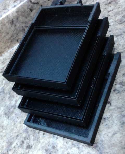 But the 28th
brought frustrations printing another cell. In the first one, a slot to
hold a fold of separator paper printed out too thin to insert anything
but a thin, hard knife blade into. As I widened that for the next try,
it occurred to me that the outer walls were probably thicker than was
needed, and I reduced them from 3mm to 2. The cell printed out with
hollow outer walls, just an inner and an outer strip. The cell would
surely leak with such thin sides and so little to glue the other face
onto. It would have been just about right for my internal slot. I
remembered having this problem before, and that making walls a bit
thicker solved it. So I tried 2.25mm. I got the same thing with a wider
slot. Apparently it needed to be just a bit wider. So I tried 2.5mm. I
got an even wider slot! By now I was just 1mm away from the original
size. It was either use the original size, or make the walls so narrow
the two strips merged into one wider one - but still thinner than I
wanted. But even if I tried that, it might just decide to print only
one strip instead of two and so still screw it up!
But the 28th
brought frustrations printing another cell. In the first one, a slot to
hold a fold of separator paper printed out too thin to insert anything
but a thin, hard knife blade into. As I widened that for the next try,
it occurred to me that the outer walls were probably thicker than was
needed, and I reduced them from 3mm to 2. The cell printed out with
hollow outer walls, just an inner and an outer strip. The cell would
surely leak with such thin sides and so little to glue the other face
onto. It would have been just about right for my internal slot. I
remembered having this problem before, and that making walls a bit
thicker solved it. So I tried 2.25mm. I got the same thing with a wider
slot. Apparently it needed to be just a bit wider. So I tried 2.5mm. I
got an even wider slot! By now I was just 1mm away from the original
size. It was either use the original size, or make the walls so narrow
the two strips merged into one wider one - but still thinner than I
wanted. But even if I tried that, it might just decide to print only
one strip instead of two and so still screw it up!
But from design to finished print is about two hours and
after four "duds" by then it was too late at night to try again. Try #6
was good on March 1st.
Then I thought of the rubber "O" ring around the filler
hole idea and the design changed again.
Also on March 1st I decided to try dumping the electrolyte
in cell #2 and refilling to see if that would reduce the self
discharge. A fair amount of black powder crud came out too, suggesting
that I still don't have the negode sealed in very well. Performance
went up yet a little more with the best current capacity yet (800mA
into 1 ohm is still pretty feeble, but better than 400), but the self
discharge went up too, suggesting that it may
be crud between the plates causing it, not the chemistry. Must improve
those seals!
Battery Cell Assembly Procedure - Version 2
Several objectives were set in design of the battery case,
and which should also be borne in mind during assembly. It was made
with one side open in order that the internal components could be
carefully laid in on top of each other by hand assembly. This does
however make making sure there are no leaks even more critical than
usual. Unless the edges are carefully pressed together during gluing,
they're almost bound to leak. But leaks on the top are bad too.
Generally, especially during the early stages of initial cycling and
breaking in, a considerable amount of gas bubbles up (hydrogen and
oxygen - they come form the water), and the top of the cell becomes
sudsy. The suds will bubble out any gap and the liquid will get low. So
sealing around the terminals with heat glue (or epoxy?) should be done
thoroughly, with care. Likewise, the 3/8" glass ball covering the
filler
hole should be a good seal against the "O" ring, and the spring is
employed to hold it in
place even against slight pressure.
The next objective is that the electrode substances,
powders compacted into a porous "briquette", stay in the pocket
intended to hold them. Again the objective is to prevent leaks - of
powder material. The
briquette is usually very fragile and crumbly until the cell has been
cycled a while, and the positive one especially tends to swell when the
electrolyte is added and when charged. Of course it isn't possible to
simply encase the pocket - electrolyte has to flow in and out. So the
pockets have been designed to try and eliminate all gaps around the
paper (or cloth?) retainers. In the same vein, the pockets try to have
little or no extra space, in order to hold the briquette securely with
minimal possibility of swelling. Swelling is a reduction of compaction
of the briquettes - which causes reduction or even loss of electrical
contact, reducing current capacity or even making portions of an
electrode non functional, "passivating" them.
Another objective is that the briquette chemicals make
good electical contact with the current collector sheet. To this end
graphite (+) or zinc(-) powder is added to the briquette, and the
surfaces of the current collector are clean and textured or roughened
to make many
points of good contact. (Grills would be ideal if there was such a
thing as either a graphite or a zinc grill available.)
Finally, this is a liquid filled battery because the high
voltages make gassing almost inevitable, which would create dry cell
bursting pressures. Gas bubbles need
an escape passage. The spacer bars between the two electrodes are
designed to provide narrow vertical channels for the gasses to bubble
out from
anywhere within the electrodes, without the gas having to escape
through the separator paper and out its top edge.
I'm putting the latest 3D printer battery case design on
line temporarily at: AlkalineCellCase-1.scad
, TrodeBasket-1.scad
, and FillerCap-1.scad
. The missing face of the cell should be cut from a thin piece of ABS
sheet.
Here's the revised cell assembly procedure based on
the experience of putting the second cell together, skipping the
previous
pictures.
1. Prepare the internal components:
- Positive current collector, positive briquette, positive separator
paper, separator basket,
negative separator paper, negative briquette, negative current
collector.
Notes:
- the positive briquette powder should be wetted with toluene or
"Diesel-Kleen" rather than water, as well as with Sunlight dishsoap.
- The negative briquette should be torched across the surface for a few
seconds after compacting.
- The negative (zinc) current collector should be roughed up with
sandpaper on the electrode facing side. (In fact, I prefer to punch a
bunch of tiny holes in it, and have the ragged edges facing the
electrode to make good contacts. I plan to make a punch with a bunch of
spikey points, to be hit with a hammer with a soft wooden block under
the zinc sheet.)
- The positive (graphite) current collector should be, at least,
roughed up with a wire brush to make better contact with the electrode.
Or, a sewing machine with a broken needle can punch a bunch of ragged
holes in it. Ideally there'd be a graphite grille, but I haven't found
such a thing yet.
2. Prepare the case: Sand the outer outer face edges flat and smooth
with a big piece of sandpaper on a flat surface, file or cut out sags
in the 3D printed
posode terminal
slots, and smooth out the seat for the "O" ring around the filler hole.
I've been using drills, but the last one grabbed into the plastic and
ripped it, ruining the cell. (3/8" marbles: Michael's Crafts store,
flower
arranging. Ball bearings seem nice at first, but they rust. 3/8" were
the smallest marbles I found.)
3. Cut & prepare the top side sheet plastic piece.
(69.5 x 98.75mm + 25 x 25 mm negode tab. A short fourth lip around the
filler hole is nice.)
4. Slip the 'flexible graphite' positive current collector tab under
the
slots and position it in the 65x65x4.0mm lower box.
5. Fill the top slot with heat glue so the terminal won't leak. Get
some in behind too, with a thin knife or something. (work fast on
that.) (This step may optionally be done after assembly is complete.
But if
you break the graphite now getting some glue under it, it's easy to
pull it out and start over.) Also heat-glue the top end of the inner
slot to prevent escape of electrode material through the tab slot into
the upper chamber. (this spot must be done now while the case is open.)
6. Optional: surface treatment of graphite current collector to
improve surface
conductivity: acetaldehyde doped with osmium. (More on this later.)
7. Drop about 5 cc of toluene (methyl benzene) with a dropper to wet
the graphite sheet.
(May not be advisable if 6. is done.)
8. Place the posode briquette in the lower box on top of the wetted
current
collector. Some graphite will dissolve, and as the toluene evaporates,
it will come out of solution
form more conductive random lamilae and nanotubes to improve
conductivity between the graphite sheet and the graphite powder in the
electrode. (around
40% more conductivity) Give it some time to evaporate. (until it
doesn't stink of toluene.)
9. (blank)
10. Insert a piece of 70x68mm
watercolor paper into the slot at the top (interior) edge of the
briquette. Fold it down to cover the briquette with the edges on the
surrounding plastic ledges.
11. Place the separator basket on top of the paper. Press
the edges down
and glue it in (3 edges) with methylene chloride. Let it harden.
12. Place a 64x70mm piece of watercolor paper into the basket, folding
it up the side of the basket at the top and bottom (where there are no
lips at the edges).
13. Place the negode briquette in the top basket, on the paper.
14. Place the zinc current collector on top of the basket with its
terminal extension sticking out the 'minus' slot. (If the electrode is
thinner than the height of the sides of the basket, the zinc sheet
could be cut carefully to fit within the basket, on top of it... Must
make the electrodes thicker!)
14b. (?) Put some foam rubber on top to press the zinc current
collector down against the electrode.
15. Run a bead of methylene chloride
around the outside edge of the case and put
on the top face of the cell. (Avert your nose. Wetting the fingers
with it seems okay but it's not good stuff to breathe.) Clamp the cell
in a
book press or between two plates of metal with C-clamps while the
solvent evaporates and the plastic hardens. I found pressing with
fingers for a minute or two isn't good enough - if it's not well
clamped for a while, it's likely to leak.
16. Use heat glue to seal the "+" terminal slot, including some between
the zinc and the plastic tab. (It's okay to bend the zinc out enough to
get behind it and ensure a seal.)
17. Punch a hole in the graphite and in the zinc terminal, put in
stainless steel washers, machine screws and nuts. Loosely put on a
second
nut to attach connection wires.
18. Fill with electrolyte, pouring from a small beaker, using a fine
funnel,
eyedropper, syringe, small flex hose or ??.
Liquid level should be well above top of grid. For a while, liquid will
be lost fairly rapidly during charging and it will need to be topped
up. (If you can find translucent
or transparent plastic for the flat face, it would be great for seeing
the
level! I take a flashlight and look in from the top. Note: acrylic
plastic will crack to pieces if it contacts toluene.) Once the initial
charging is done, I've found that it looses liquid until it's down
about 3/4 inch from the top, then it stops going down. (I think I
should make the cells a little deeper.)
19. Install 11.5mm O.D. rubber "O" ring in filler opening, place 3/8"
glass ball on it,
and put cover clip over the ball.
Now it should be charged to about 2.4 volts. Then it needs
to rest quite a while (a few hours?), during which it'll self discharge
considerably.
Then recharge. It's a good idea to change the electrolyte after initial
use to
eliminate any
soluble impurities. That might also depend on the source of the
ingredients. Charging at maybe 2.7-2.8 volts, it should sit for a time
at
around 2.6 volts after the charge is removed. Best charging and
operating conditions have yet to be established.
NiMH Batteries: safety issue, operating tip: don't tip them!
Inspecting January's burned up MiMH battery pack
disclosed a big contributing factor: the cells were all soldered
together next to each other, and when one overheated enough, the
plastic cell cover melted and two metal cases touched, creating a short
circuit between cells. The heavy current in turn made more heat,
melting more cells together, so the whole pack went up in smoke and
heat - lots of it - very rapidly.
This means that the newer "battery sticks" are much safer
than the original soldered-together packs, which I had quit making in
any event. But in all new NiMH battery case designs, I'll make sure
that all cell sides are physically separated and insulated from each
other, and with good ventilation between. Perhaps it's just as well I
had trouble printing the 10 cell cases that would again have abutted
cells side by side.
There was another battery incident in February, again when
only a
few batteries were connected. Two 12V battery sticks were hot, and one
was so hot the plastic drooped when I picked it up (off the firebrick
lining this time!), ending up like some
crooked thing out of Dr. Suess. Outside, I broke open the tube and
dumped the hot D
cells into water. Given the heat and melted labels on the bulging
batteries, it's surprising that they all still work. A soldered
together pack with cells abutting each other would have suffered the
same fate as the first pack.
It turned out that the DC to DC converter stops regulating
properly
and starts putting out higher voltages if there isn't enough load, and
a small number of batteries isn't enough load. This was the cause of
the
battery problems. Now I leave a 1 amp LED light on when the fridge (7+
amps... to be cut in half soon...) is off. Obviously this can only be a
temporary solution and a
whole intermittent "energy hub" system to tie everything together
properly - and perform properly in any reasonable conditions - needs to
be developed.
I was talking to someone who had been using NiMH cells for
electric bicycles. He said that when the cells were overcharged and
they vent, the ones that were oriented with the "+" button up would
vent gas and still work. The ones that were facing down vented their
electrolyte and didn't work any more. (So much for "dry cells"!) The
moral of the story was to
keep them all facing upwards. even better, to not overcharge them.
Wherever practical I'll try to adopt this configuration.
For a stationary installation like solar, it should be easy to orient
12 volt battery sticks, 26" long, all facing up. But for transport and
the vibration and bumping that go along with it, there'd be a lot of
pressure trying to dent the lower cells. The 6 volt sticks would need
wires from the top of one set to the bottom of the next instead of just
copper straps straight across. Ideally, use the 13.8-13.9 volt float
charge to ensure they're never overcharged and don't worry about
orientation. But the equipment has to work and not do unexpected things
under the wrong circumstances like the Zahn DC to DC converter proved
it does.
http://www.TurquoiseEnergy.com
Victoria BC