Turquoise
Energy Ltd. News #62
Victoria BC
Copyright 2013 Craig Carmichael - April 4th, 2013
www.TurquoiseEnergy.com
= www.ElectricCaik.com
= www.ElectricHubcap.com
= www.ElectricWeel.com = www.MushroomOutboard.com
Features: Electric Mazda RX-7 &
a Better Battery Strategy for EV's
Month In Brief
(Project Summaries)
- New Electrode Edge Compactor & MnMn Battery #3, Thermoelectric
heat pump & fridge, Evacuated Pipe "Heat Diode" radiators, Mazda
& EV battery strategy.
In Passing (Miscellaneous
topics, editorial comments & opinionated rants)
- Inequitable Wealth Distribution - Banking System Suicide - Magnetic
Projectile Launcher Idea - Poland Attacks Germany Replay?
Electric Transport - Electric Hubcap Motor
Systems
* Lead-acid battery renewal & better battery charging system for Mazda
RX-7
* Better clutch idea for Sprint transmission
Other "Green" Electric Equipment Projects
* Peltier module tests & research for making a heat pump for space
heating
* Peltier fridge uses 1/2 as much power for the same cooling: Max
efficiency!
* Evacuated water/steam tube radiators - "heat diodes"
Electricity Generating (nada)
Electricity Storage - Turquoise
Battery Project etc.
* New edge-feed electrode compactor
* "Production Prototype" Cell #3 - assembly - testing:
- Much better than #2... and gradually improving with charging.
No Project Reports on: DSSC
solar cells, LED Lighting, Pulsejet steel
plate cutter, Magnetic
Motion Machine, Large
format NiMH batteries - take 3, CNC Gardening/Farming Machine,
Woodstove Electricity Generator.
Newsletters
Index/Highlights: http://www.TurquoiseEnergy.com/news/index.html
Construction Manuals and information:
-
Electric Hubcap Motor - Turquoise Motor
Controller - 36 Volt Electric
Fan-Heater (say, this heater is now obsolete! Use Peltier module heat
pump!)
- Nanocrystalline glaze to enhance Solar
Cell performance - Ersatz 'powder coating' home process for
protecting/painting metal
Products Catalog:
- Electric Hubcap Motor Kit - also please inquire about Electric
Caik
3KW Motor Kit
- Sodium Sulfate - Lead-Acid battery longevity/renewal
- NiMH Handy Battery Sticks & Dry Cells (cheapest NiMH
prices in Victoria BC)
- LED Light Fixtures
Motor Building
Workshops
...all at: http://www.TurquoiseEnergy.com/
(orders: e-mail craig@saers.com)
March in Brief
I
couldn't upload the February newsletter to the web for at least a week.
The server
just kept closing the connection. I went to enquire on about
the 13th, but first I tried it yet again... and everything worked fine!
This month's 'short' e-mail version newsletter is somehow almost 1/2 as
long as the web version with the ad nauseum detailed project reports.
For a while I couldn't seem to settle down and get at my taxes, nor
concentrate too long on anything else. I picked away at various things.
MnMn Turquoise Battery Project: Production Prototype Cell #3
One of the things I worked at fitfully was the
battery project, 2 or 3 hours now and then. I made the improved
electrode compactor box, and finally put together 'production prototype
cell #3' by the 17th. Edge compaction of the electrodes seems to work
out well, using pressures that are easy to attain. It does preclude
putting a conductive grill in the electrode, but I haven't found any
zinc or graphite 'screens' anyway. Except for a couple of glitches to
work out in the case design for #4, it went together well, and I had
fair hopes for it. One thing - maybe the only thing - that was still
going poorly was the negative electrodes - they seemed poorly
conductive, and were probably also the culprit for very low amp-hours
capacity. But the cell initially had double the capacity of #2, and it
doubled again over the rest of the month. If it continues to improve,
after 3 or 4 months it may be a fine battery!
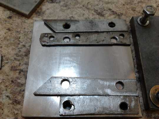
In order to get flat electrodes instead of ones that bulge in the
middle, I put together a new electrode compactor.
The faces are 3/8" thick stainless steel, sanded and polished up as
best I could on the inside.
Two sets of sides (new, old with new holes) make electrodes 2.3 or
3.1mm thick - or I suppose 5.4mm.
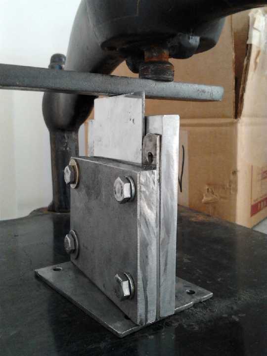
Compacting electrode powder into the box, using the book press center
screw as a fulcrum,
and a steel bar like a lever or arbor press handle to press the die
into the box.
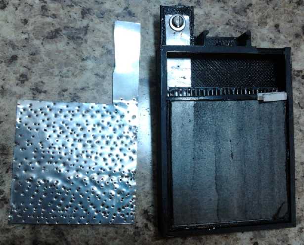
Compacted negative electrode, about to be covered by perforated zinc
foil current collector.
After that, the front face was glued on and the cell was ready to fill.
(Underneath at back is positive electrode laid on flexible graphite
current
collector. Top end of vertical bar separator grille is visible.)
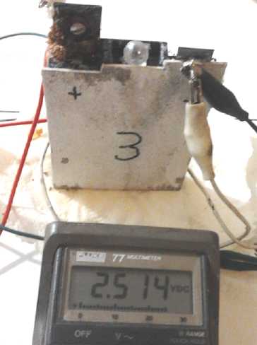
"Production Prototype" Cell #3 after a couple of weeks.
At the left crystals are growing from a small leak around the positive
terminal.
Peltier Fridge Improvements &
Thermoelectric Heat Pump
Another thing I picked away
at was the idea of flattening a larger diameter pipe to mount
peltier modules on so they could have flowing water right behind them.
But having made a couple, I fear the pipe may "cup" a bit in the center
when they're clamped on, preventing good thermal contact of the entire
module. And the evacuated tube system being developed may eliminate
having water behind the modules.
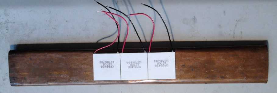
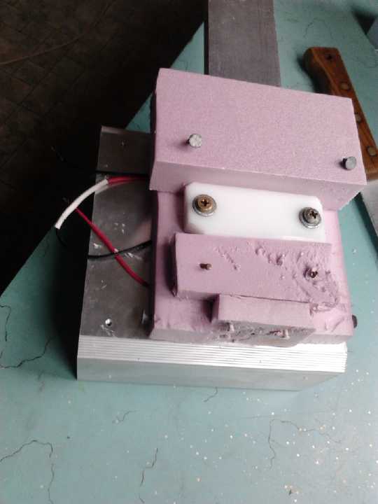
1.5" copper pipe, flattened to form a "water box" to hold and
dissipate heat or cold from peltier modules.
(One peltier module, a thin white square, is shown sticking out a
little.
These are clamped between the copper bar cold side and the
aluminum heatsink warm side.)
 At about mid month I tried to use two peltiers each at 1/2
voltage to
make the fridge more efficient. I spent several days on that instead of
the
intended 2 hours, determined to make it work well in spite of various
setbacks. Finally it was refrigerating just as well at about half power
- around 3 amps instead of 6 amps, 40 watts instead of 80. It looks
like a winner!
At about mid month I tried to use two peltiers each at 1/2
voltage to
make the fridge more efficient. I spent several days on that instead of
the
intended 2 hours, determined to make it work well in spite of various
setbacks. Finally it was refrigerating just as well at about half power
- around 3 amps instead of 6 amps, 40 watts instead of 80. It looks
like a winner!
It demonstrates that Peltier modules are currently being
employed in less than efficient ways.
I had previously been
thinking of a peltier fridge as a niche market item, and thought that I
was to some extent wasting my time on it. But a quiet or
even silent fridge might be considered an "up-scale" appliance, even
worth paying extra for. It might be attractive to many homeowners, and
especially to apartment dwellers where the fridge's compressor noise
often
permeates the whole living space.
A new thing I tried was an evacuated pipe "heat diode"
radiator with a
bit of water in
the bottom to replace the warm side heatsink and fan. When the water at
the bottom is heated by the peltiers, it immediately boils. The steam
rises up the cool tube and condenses as it cools, and runs back down.
Quickly the heat at the bottom is transferred throughout the whole
pipe, and is radiated off by the cooling fins. Cold at the bottom
doesn't get transferred up the pipe except gradually by the copper pipe
walls.
This
wasn't immediately successful owing to insufficient vacuum, resulting
in a boiling point of about 38°c instead of under room temperature,
but it has much
promise for a most effective
and completely silent (well, except for some 'pinging' bubble noises)
fridge.
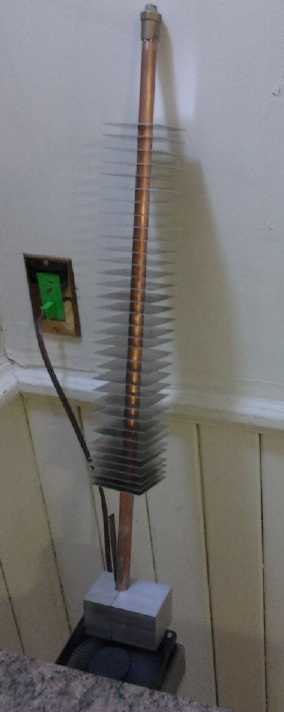
Evacuated Pipe "Heat Diode" Radiator with aluminum fins,
and aluminum block peltier module thermal interface.
(Oops, I didn't get a picture when I had it installed.)
Then I decided the
heat pump should take priority and
really should be built and tested this month. I worked on it a while
and installed a cold side radiator loop on the outside wall, but didn't
get it there. The
closely related work on the fridge continued and led to great ideas
about evacuated tubes for better heat radiation, with conduction loss
reductions when the heat is off. Thermoelectric heat pump potential for
saving as much
as 1/2 the electricity used in electric heat and the consequent
potential reduction in total power grid consumption seemed
valuable. And like the fridge it
would have advantages over compressor & refrigerant heat pumps in
being quiet or almost silent, plus it would be installable by a home
owner without special skills.
A switch to thermoelectric heat pumps and LED lighting
would
surely save more electricity than the total amount of increase that
would accompany
converting all road vehicles to electric drive. There is interest from
both potential customers and investment. Improving the fridge really
was a precursor to it.
The TEG2.0 thermoelectric generator modules tested out
very well as peltier modules, providing good coefficients of
performance at low voltages. I decided to use eight of them in the
liquid based TEG unit, as designed, as the first prototype
heat pump instead of as a woodstove electricity generator. (Did I
mention that all these thermoelectric things
are very closely related?) I'll cut the woodstove generator in half
from 16 modules to 8 for the time being.
Just before the end of the month the weather warmed up
dramatically. Unless there are some cold spells it may be hard to test
the woodstove electrical generator and heat pump units under "real
life"
conditions until next fall. That doesn't preclude heating a room up
like a sauna just to test.
Electric Mazda, Battery Renewal and Superior Charging System
On the 23rd I was offered excellent terms and a very low
price - 2500$ - for a 1982 electrified Mazda RX-7 that no one else
seemed to want. In addition to being old, it needed at least "3000$"
worth of lead-acid batteries
to put it back on the street. Since none of my car electrifying
projects are on the road yet (sigh!), I took it. I figured I could
scrounge some "deep cycle"
batteries to renew with sodium sulfate without spending a lot of money.
I had 3 and needed at least 8. I obtained 6 more before month's end and
emptied out the acid.
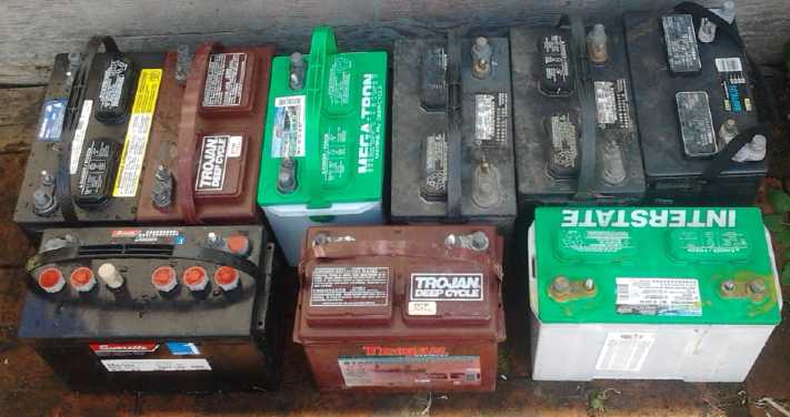
My "set" of miscellaneous batteries for the electric RX-7.
The second key to making this work will be to charge each
battery with a separate 12 volt
charger. That's far superior to charging them all in series from one
charger: a weak or misbehaving battery can't damage the others during
charging. Any assortment of batteries will work fine, with driving
range of
course dictated by the one with least capacity. When a battery gets
weak, it can be replaced individually, avoiding the need to replace
them all at once... which is what took this electric car (and seemingly
many others) off the road in the
first place. (After a long drive, the batteries can readily be tested
with a
voltmeter to see which one(s) lost the most charge.) I may even use
some
NiMH D cells for a battery or two, just to show the point. (Who's ever
heard of mixing PbPb's with NiMH's?)
On the 27th I went out to hunt down some old 'deep cycle'
PbPb batteries. One place that used to sell them would only buy them,
and that proved almost universal. However, Battery Doctor was willing.
I got 4 there, and they said they'd have another one the next day. With
the 3 I already had, that gave me the minimum number (8) for the main
cost of a long session of dumping out 'pants eating' acid, neutralizing
it and disposing of the lead crap (feeding it into dead batteries going
for recycling), and refilling with sodium sulfate solution.
A couple of the batteries were size "24" instead of "27".
Those will be the ones that limit the car's range and will probably be
replaced first when and as I find better ones.
Another one for the road?
Someone hopes to buy a one of a kind 1970's electric jeep.
Evidently it has some odd switches and levers for speed control, which
ought to be updated to a modern PWM controller. It's a 36 volt drive
system. That's the voltage of my Turquoise Motor Controllers, so I just
may be supplying the control to make it really drivable. It's
interesting to realize how far power semiconductors have come that a
PWM controller for a powerful motor was impractical in the 1970's.
Chev Sprint Transmission
I also came up with another new plan for the Sprint
clutch. I
started losing confidence in the centrifugal clutch idea without having
tried it, as it began to sink in that it probably won't engage at the
RPMs the shaft will attain, and also that I might want it to engage at
various RPMs and torques depending on driving conditions.
Then it occurred to me that instead of adding two idler
pulleys (for forward and reverse) to engage the clutch, I could mount
the whole lightweight motor and torque converter assembly on a
pivotting mounting. To engage, the whole assembly would pull away from
the lower side with the differential and its pulley, tightening the
flat drive belt. It sounds like a big deal, but I think it would
actually be easier to do this than the idler pulley assembly, and it
should work more smoothly.
Now if I just could find any time to build it! I don't see
how I can do the CNC Gardening Machine this spring, either, along with
the several other potentially valuable things listed under "No Project
Report On:".
Fine Print
On the 24th someone had the nerve to tell me the text font
I've been using in my newsletters was absurdly large. Well, I think
some website text is absurdly small. It's as if everybody wants to
continue to use the same number of pixels per character no matter how
much finer the pixels have become, and fit an inch of text into 2/3 of
an inch no matter how much more viewing space there is with bigger
displays -- and then make big margins with flashing pictures to spoil
the reader's concentration. (Text also seems to continue to shrink as I
get older.) I
figure I'd rather sit back and look at the monitor from a couple of
feet away than have my breath fogging it up while I go more and more
shortsighted. Okay, probably I swung the pendulum too far in reaction
to all the needlessly fine print and then never gave it any more
thought... so this is the next common size down, still larger than
most. (which I've already been using lately in the e-mail short
version.) If this text was too small to read and so you didn't get this
far,
let me know.
In Passing
Incidental news, editorial comments & opinionated rants
I saw a video on youtube called Wealth
Inequality in America. You already know it's bad, but even so it's
shocking almost beyond belief:

http://www.youtube.com/watch?v=QPKKQnijnsM

1% of Americans have 40% of the nation's wealth. 80% have only 17% of
it
between them. And the figures used were from 2009 - it's worse now. And
broken down further, "the 1% of the 1%" in fact have much of the wealth
attributed to "the 1%". At that point we can virtually start naming the
individuals who
have the bulk of the wealth, and many of the names will be
familiar.
It then starts to become obvious why some things never
seem to change: those few with wealth and power don't want
change. To finance major production of, say, an electric vehicle
conversion system or themoelectric heat pumps, those few who could
easily dig into their spare change and make the needed investment are
the same few who maintain their vast fortunes and power off
selling gasoline and
operating power generating facilities. They would rather manipulate
such underfunded enterprises out of business whenever they manage to
germinate, lest they take root and free people from their control. At
least, that was the situation for a century, before the banksters
started outscamming all the other scammers.
Worldwide, we are arriving at the point where a large
percentage of people
under 30 have no real economic or political stake in their society -
they have no control and it's done
little or nothing
for them except order them around, put them in debt, and supply paltry
handouts. It appears they may never buy a home or raise a family. And
in fact the
remaining wealth is being stolen from everyone of all ages wherever
"the 1%" gangsters can manipulate any
slight opening. A huge disconnect has arisen, and societal breakdown
seems
inevitable. Since we live
on an evolving world in an evolving universe, since "All things work
together for the progress of men and angels", we may surmise that a
major evolutionary step of some sort is imminent.
Whether it's a sudden leap of progress or whether some new
dark age will have to intervene between today and a better world will
depend on us collectively and even on individuals. One individual can
alter the whole course of evolution. Jesus reformed religious thought
and insight around the
world. Joan of Arc rescued France. Winston Churchill rescued Europe.
Werner von Braun inspired John Kennedy and sent men to the moon - an
idea that could still be a science fiction dream. The Beatles, a
band of four, inspired a generation. Zillions of examples of
individuals who were inspired to do something and changed history could
be cited if one
wanted to dig.
Suicide by the banking system
About mid month, the "bond bubble" hinted it was starting
to burst. In
California, municipal bonds are falling and interest rates are rising.
The financial system is starting to unravel.
Debts everywhere are so absurdly huge that
rising rates will bring everything down.
Then on the 19th I heard the
IMF and ECB wanted to charge 6 to 10% to every bank account in Cypress
as part
of 'bailing out' this small economy. They even said the Cypress
parliament was
taking
too long to decide and that they would start taking out the money. The
next day, the parliament unexpectedly (but rationally) voted against
this theft - the first time an EU country stood up to the banksters.
It seemed like a citizens' triumph of sorts - leave the EU and let the
bankster/gamblers pay the price.
But Russia wouldn't bail Cypress out, and two days later
the account
theft was enacted in perhaps even more sinister form, leaving smaller
accounts but stealing far higher percentages - like 40% - of money from
accounts
worth over 100,000 Euros. Although the banks in Cypress were closed,
mainland branches of the same banks remained open, allowing the large
international account holders to get their money out. So mostly what
was confiscated was the life savings of older
people who had retired to Cypress for its sunny Mediterranean climate.
Toward month's end Cypress banks still wouldn't allow anyone to
withdraw more than 300 Euros a day after being closed for almost two
weeks.
Can they ever actually fully reopen?
Serious damage to the
viability of the whole world's banking system has been done. A
precedent has been set and trust is on the
wane. One repetition anywhere else or even the threat of one will
probably finish it. It may even sink even without one. Without
trust, there will be no
customer deposits. Without deposits, there will soon be no banks.
Without
accumulated capital, there is no
'capitalism'. Financial guru
Reggie Middleton
(BoomBustBlog.com) speaking on Keiser Report #421 (RT.com), reminds us
of
the basics: the purpose of banks is to
be a safe place to keep your money, and to pay you interest for the
privilege of using that money. The banks have failed to pay interest
for some years now,
and if they're not even a safe place to keep money, what are they good
for? Why would anyone make new deposits beyond enough to cover
immediate
transactions and monthly bills?
And even if people were so complacent as to allow their
life savings to be eroded away without trying to withdraw them, it's
difficult to imagine that Cypress' banks will somehow have the money in
cash after the bank run by the big investors - they will only be in
less debt. They are are surely doomed and
will soon need
bailouts to pay out their every liability.
At the end of the month I learned that withdrawals were
limited to 300 Euros a day, holding not only individuals' money
hostage, but companys' as well. As a result, companies in Cypress can't
pay their employees and must lay off their staff. How could anyone
cause a swifter collapse of Cypress' whole economy?
One effect of this hit me in a financial
transaction of my own: I downloaded a "Bitcoin Wallet" program about
the 14th. (bitcoin.org) It took it 3 days to "synchronize with the
web", where all bitcoin transactions ever made are recorded on all the
'anonymous'
Bitcoin Wallets everywhere with no central server, so Bitcoin can't be
counterfeited, fooled or usurped. Then I found "NanaimoGold.com"
digital
currency exchange. (Yes it's in Nanaimo BC) The price of each bitcoin
was 51$, up from 11$ a few months ago when I first figured I should
pick some up but didn't, which was up from 5$ a year ago. Since I
hadn't been
following it, this was quite a shock. It
took two days of e-mails where I got all the details figured out and a
test transmission to my 'wallet' (.01 BTC) before I sent him some money
and received a few bitcoins on the 20th.
In those two days, the Cypress banks had closed and the
crisis
was in full swing. Evidently people in Cypress and maybe
elsewhere
were buying bitcoin as a safer place to put their money, and
the price had gone up to 67$. I got 30% less Bitcoin for my money than
I would have just a day or two before! The next day it was up another
4$ to 71$. Then it lost a couple of dollars, but a week later it was
89$. This near doubling in 10 days of an experimental currency based on
ideas of almost free money transfers for online commerce and trust in
computer programming and math, shows the level of distrust in 'regular'
currencies and institutions. Now the world's first Bitcoin ATM has
opened - yes, in Cypress. On April 3rd bitcoin was 123$. The total
value of all bitcoins hit a billion dollars.
But in other lands, account money is being continually
raided indirectly by having the central banks simply print money,
eroding the value of everyones' savings. It was just estimated that in
the UK, a value of 200 B pounds (as close as I recall) was eroded from
people's total bank account savings of a little over 1 T pounds - an
indirect
theft of about 20% of everyones' wealth. This is by no means unique.
For example the USA figure is considerably higher (34% IIRC), and the
"Fed" is printing 85 B$ a month - a trillion dollars a year. That's
likely to rise.
So far, bank runs have been restricted mainly to Greek and
Spanish banks, and these banks have been propped up by [the people of]
Europe
in general. But when confidence in the
financial system somewhere is finally lost, everyone everywhere will
try
to pull their
money out of the banks. They'll all collapse, since they all retain
only a few percent of depositors' money and lend the rest out... or
worse, have lost it in risky investments. Inflating the currency is
sneaky and
hasn't led to panic yet. I can't think of any
trigger quite so likely to precipitate the banking collapse as stealing
money
directly out of peoples' bank accounts.
Sometime I started to become aware that greed had struck
at
my own credit union, Coast Capital Savings, now the second largest
credit union in Canada and no longer controlled locally on Vancouver
Island. I've banked there or at its predecessors (Westcoast Savings,
then Pacific Coast Savings) since 1977. A letter came to members asking
them to vote on a "special resolution" that 'members must approve of
the
annual salaries
and benefits of the board of directors'. The directors 'were required
to
put forward the member's special resolution', but advised the members
to vote 'no'. In other words, they don't want the members to know what
they're giving themselves.
The proponent states that the CCS board has
been paying themselves more than double what the board of the largest
credit union earns, and that they decide their
own benefits without members knowing about them. With uncontrolled
greed evident, can
fraud, corruption and probably insolvency be absent? I voted 'yes' on
the
resolution, but I closed my Turquoise Energy account and have only
petty cash left in my personal account. I don't have much more than
that to
my name at this time anyway, but I certainly don't want my annual tax
refund money (to pay off my debts!) in the hands of a shaky
institution. BC credit union deposits are 'insured' by the province,
but does BC have
the money to pay out if its second largest credit union collapses? I
opened an account
at Island Savings Credit Union, a much smaller institution whose head
office
is within driving distance. A first impression perhaps, but I felt a
welcome difference in atmosphere in the branch.
On the 28th, I was tipped off about unwelcome Canadian
news in a
silverdoctors.com article, which was spreading widely around the
youtube financial news community in connection with Cypress within a
day or two. I print the most salient points about the government
authorising itself to steal customer account money to prop up any
"systemically important" banks if they should happen to fail, buried on
page 144-145 of the 2013 national budget:
"...it appears
that the Cypriot bail-in is anything but a one-off event, and is in
fact
the new collapse template for the entire Western banking system, and
not just the ECB/ Eurozone!
SD has been alerted to an alarming provision that has been buried deep
inside the official 2013 Canadian Budget that will result in depositor
haircut bail-ins jumping to this side of the pond during the next bank
crisis!"
A subsequent CBC article on the subject ended with a piece
of good advice:
"The fact is, if Ottawa is seriously contemplating the failure of a
Canadian bank, ordinary Canadians might want to do the same, and govern
themselves accordingly."
Wherever the next theft of
peoples' savings occurs, the
third country probably won't have to worry about what to do, because
worldwide bank runs will have already happened. (Ha! -- One youtube
video was
titled "How to Survive a Bank Run". It began: "What, you still have
your
money in a bank!?! <LOL> Get it out now while there's
still time!" And that was before Cypress.)
Magnetic Gun Design Idea?
I watched a documentary (youtube) on 3D printed guns. It
was interesting, but I thought they were doing it the hard way. They
were 3d printing fairly complex parts for traditional explosive shell
guns, with a less than common laser/resin bath 3D printer.
It seemed the problem with a magnetic gun might just be a
barrel. It's quite a different proposition, since everything works
differently. It seems that the projectile (eg, ball bearing?) doesn't
touch the barrel, but is held centered by the magnetic forces. But the
succession of coils accelerating the ball has to be held in a straight
line. Another consideration is that the projectile must interrupt
an optical sensor in order to know when to turn each coil's mosfet on
and off for best acceleration.
So I thought of a stiff acrylic plastic tube... better
still a lexan tube. It's transparent. Lexan is very strong. Then the 3D
printer can print two simple parts. Part one is one side and the center
part of a bobbin/spool to wind the coils onto, just big enough to slip
over the 'barrel'. Part 2 is the other side of the bobbin with places
in which to mount an LED and a phototransistor. This is
glued to the first section to form a complete accelerator coil/sensor
section.
As many of these as might be deemed useful are wound, the optics
installed, and slipped over the barrel. And then probably just glued to
it. It just seems so simple. (Circuits to control the firing
sequence
are readily available on line.) Conceivably I could see an effective
projectile launcher powered by nothing more than a D cell or two.
Doubtless one would run into various construction considerations if
one actually attempted building one.
So far I have no use for such a thing myself, unless
grizzly bears are spotted in towns on the south end of Vancouver
island. (Well, I'm not very fond of cougars, either, and once there was
one in a tree across the street. but that was 3 decades ago.) I'd
rather
make axial flux car motors and thermoelectric heat pumps to save
electricity and make life more pleasant for all. Those who need to
shoot pesky rabbits or grizzly bears, put down a revolution by unruly
peasants, fight a brutal government to regain lost liberty, or put a
molten
blob of steel into orbit, can work out the details for themselves.
Poland Attacks Germany Replay?
On the 25th I went to youtube and found a bunch of new
videos saying that Iran's "supreme leader" (apparently not the
president) has 'vowed to wipe out Tel Aviv and Haifa', while Obama was
in Israel - probably conferring with Nettenyahu on the invasion of
Iran. This was so
ridiculous, so contrary to anything the host country of last year's
NAM ("non aligned nations") conference has actually been saying and
anything it's in their interest to say, that I didn't even look at any
of them. Even if such provocative words were used (in contrast
with Abadiminijad's moderate, cool-headed statements that get twisted
into "threats to annihilate Israel" in translation to English for the
American
public), it would obviously have been prefaced with "If we are
attacked by Israel..." It's a pretext for the gullible, to "justify" a
war for control of Iran's oil, so obviously long planned by the USA and
Israel. (As Greggory Mannarino (TradersChoice.com, youtube) says, "Iran
has a
target painted on it.")
It's a close parallel to Hitler's Germany saying Poland
had attacked on September 1st 1939 -- a couple of hours before the
German war machine predictably rolled over Poland as had been
obviously
planned for some time, crushing it in a very few weeks and incidentally
starting world war two. Germany killed some people they didn't care
about after dressing them up in Polish uniforms, to have pictures for
the newspapers of the 'vile invaders who had stormed over the border',
to "justify" their attack.
Anything Hitler could do, Obama can do better. It's also
reminiscent of GW Bush claiming there were "weapons of mass
destruction" to justify his long planned attack on Iraq. With Syria,
Iraq,
Iran and Afghanistan all lined up plus a Libyan entry point into
Africa, the USA would
control through the Mediterranean a huge empire of oil-rich states
whose former
leaders (Saddam Hussein, Moamar Qadafy) each tried to get away from
using the USA "petrodollar"
for trading oil. (Iran has been forced off it by US sanctions.)
The funny thing is, tho, that it would appear Iran may
well be able to beat off
the attack unless the USA and Israel use nuclear weapons against them.
It would be little consolation then that that would show Iran
would
have been fully justified in making nuclear weapons
themselves as a deterrent.
And what of North Korea, which actually has
nuclear weapons and missiles, and not only that, is actually is
threatening to use them in a first strike against the USA (in
retaliation for US led sanctions)? Well... there's no oil in North
Korea, and it doesn't lie between Iraq
and Afghanistan, so who cares? Some youtube skeptics think the North
Korean
"threat"
is a just a decoy inspired by the US government to distract the
public's attention from the plan for war with Iran and ever growing
control of the USA by the gestapo, er... DHS, et al.
Electric
Hubcap Motor Systems - Electric Transport
Lead-Acid Battery Renewal and a Superior Charging System:
Low Cost Ideas to put Idle Electric Mazda Back on the Road
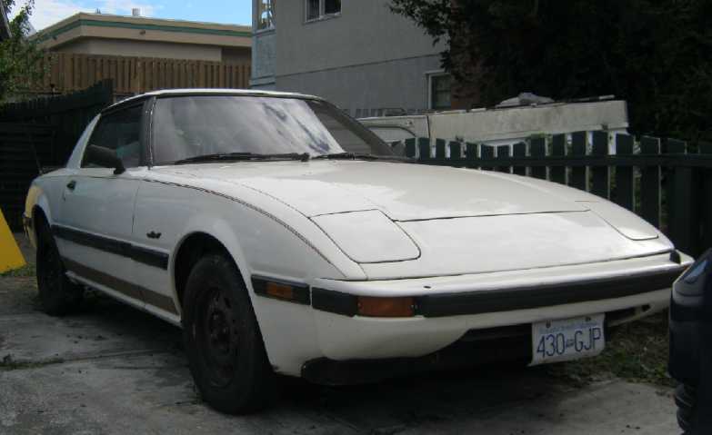
On the 23rd I was offered irresistable terms and a very
low
price - 2500$ - for a 1982 Mazda RX-7 converted to electric in 2003 and
driven until 2010, now for sale by
Jim Harrington. He
bought it simply to see what went into an electric conversion. He
already has a nice new Mitsubishi iMiEV, so after checking it over, he
had no further use for it except an idea to transfer the motor and
drive system to a Mazda
pickup
truck for deliveries, which naturally would have been a lot of work.
Surprisingly, no one else seemed to want it - I guess
because
it was so old and it needed "at least 3000$" worth of lead-acid
batteries
(or maybe 6-7000$ for equivalent(?) NiMH dry cells, or still more for
lithiums)
to put it back on the street after 3 years. Well, my Chev Sprint isn't
on the road
yet (much less the Toyota 4runner), and I haven't managed to
"hybridize" a gas car with a hubcap motor. So I thought about
it overnight, and decided that even as a "conventional" conversion, a
bird on the road would save more gas and pollution than two in the back
yard. And it couldn't hurt someone trying to create improved EV's to
have some first hand experience with a 'conventional' converted EV.
Furthermore, I have a plan to potentially make electric
cars, even with lead-acid batteries, more practical. Typically,
all the batteries are replaced at once with an entire complement of
identical, new batteries. The overall budget is substantially less than
buying
gasoline (if I had it worked out right 4 or 5 years ago), but it's a
sudden great expense that tends to remove EV's from the street.
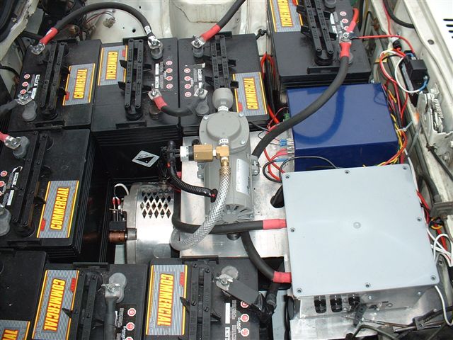
Under the hood, back when it had 18 - 8 volt batteries. The
other 10 were in the
back.
 The problem is
that they are usually all charged as a single
string of batteries, and any battery that's a little different from the
rest either is stressed or stresses the rest during charging. As they
age, they may start to differ, accelerating the need for replacement.
The problem is
that they are usually all charged as a single
string of batteries, and any battery that's a little different from the
rest either is stressed or stresses the rest during charging. As they
age, they may start to differ, accelerating the need for replacement.
I plan to charge each battery with a separate 12 volt
charger. Those
are pretty cheap, and it seems to me it's a
far superior method. Any
assortment of batteries will work fine, with vehicle range of course
dictated by the one with least capacity. When a battery gets weak, it
can be replaced individually, thus avoiding the need to replace them
all at
once... which is what took this car off the road in the first place.
(After a long drive, the batteries can be checked with a voltmeter to
see which one(s) lost the most charge.) I may even use some NiMH D
cells for a battery or two, just to show the point. (Who's ever heard
of mixing PbPb's with NiMH's?) There's then the possibility of
gradually
replacing the lead-acids with a better type - even "types", again one
at a time instead having a sudden huge bill to pay. One NiMH (or
lithium) 80
amp-hour battery made of 80 dry cells in "battery stick" tubes would be
around 500-600$ - costly, but much more palatable than 6000$ or more at
one shot.
(and BTW worth perhaps 120 AH of lead-acid, and BTW that charger would
have to be adjusted or replaced with one suitable for the new type.) Or
of course, if I manage to get the MnMn cells working really well,
they'd be cheap and presumably better than anything, and again could be
substituted a section at a time.
This charging method isn't exactly an original idea - I
saw it
in a youtube video. It was a component of someone's electric car
project video(s). He had identical batteries with a charger mounted
over each one, and he didn't make any
special point of it or explain why. I thought it
seemed hoaky at the time - I figured he just got a bunch of chargers
'on sale'
somewhere. Later I started to realize its
advantages.
With separate charging in mind, I figured I could then
scrounge
some "deep cycle" batteries to renew with sodium sulfate without
spending a lot of money. It seems they last considerably longer when
renewed with
sodium sulfate than when purchased new anyway. (I did mention this
possibility to
others before I bought the car myself, but
it didn't seem to sway anybody.) I had 3 already from earlier 36 volt
Electric
Hubcap tests and battery renewal experiments, and needed at least 8
(for 96
volts). Each
additional battery beyond
that to 12 (144 volts) can
add a bit of performance and range.
On the 27th I
went out to hunt down some PbPb
batteries. A recycling place that told me a couple of years ago they'd
sell them now
will only buy them, and
that proved almost universal. Even the dump wouldn't part with an old
battery for love nor money. This seems rather uncharitable when people
to drop off these old batteries for free. You know
the original owner would just as gladly have given it to you as to
them. However,
Battery Doctor was willing. I
got 4 there, and they said they'd have another one the next day. They
got two, giving me nine. The monetary cost was low, but
they got more from me than by shipping them out for recycling. The main
cost was a long session of dumping out the 'pants eating acid' while
holding up and shaking these very heavy batteries (with my bad back -
now quite painful again after a long time without pain),
neutralizing
it (I used potassium hydroxide, making potassium sulfate salt. Baking
soda should work, but it would have taken quite a lot. Hmm... with
sodium hydroxide I could have made more sodium sulfate to renew with!
Why buy it?), and disposing of the lead crap (feeding it into a dead
battery
definitely going
for recycling, or saving it for glaze making), and refilling with
sodium sulfate solution.
A couple of the batteries were size "24" instead of "27",
and some of the "27"s had less capacity than others.
Those will
be the ones that limit the car's range and will probably be replaced
first when and as I find better ones. It still looks like a good
starter set - as long as they're charged separately!
I got the Na2SO4 into one battery on the 31st. Instead of
my usual technique of "1 gram per cell per 2 pounds of battery weight",
I
mixed the salt with warm water (Britta filtered and warmed on the
stove) to a specific gravity
of about 1.15.
Sodium sulfate isn't the most highly soluble salt, and it
couldn't be made much thicker than that. It's far more soluble in warm
water than
in cold. But in the battery, it converts into twice as much acidic
sodium bisulfate, NaHSO4, with sulfate desulfated from the plates. This
replaces the sulfuric acid, H2SO4, or some of it, and it appears to be
a
better electrolyte. I've said this before, or most of it, in
previous issues about lead-acid battery renewal quite some time ago. (I
wonder what would happen if one was to fill a brand new battery with
sodium bisulfate right from the start?)
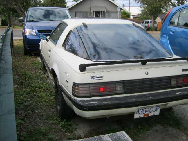
A little black touch-up paint will spruce it up?
(The back of the new iMiEV can be seen on the right.)
Assuming the plan works,
putting an EV back on the road just got affordable. But I'm not sure I
can give up the gas
car and insure only an
e-vehicle with little cargo space, even for one rather occasional
driver. Occasionally I take a
highway trip and need the range, and occasionally I have a larger load.
But with the irregular and
often short trips I usually take, even for one car the insurance
sometimes
costs me
more than all other annual car expenses combined, and insuring two cars
will double it. This is just one of the reasons for wanting to add a
motor onto
a car wheel and "hybridize" regular cars.
PGTC Car
Transmission: clutching at a
better idea
Right after saying I'd take the Mazda, I came up with
another new plan for the Sprint clutch. I
started losing confidence in the centrifugal clutch idea without having
finished or
tried it, as it began to sink in that without modification it probably
won't even engage at the
RPMs the shaft will attain, and I suspect it might well be desirable to
engage it more gradually, and at
various RPMs and torques depending on driving conditions.
Then it occurred to me that instead of adding two idler
pulleys (needed for forward and reverse) to engage the clutch, I could
mount
the whole lightweight motor and torque converter assembly on a
pivoting mounting. To engage, the whole assembly would pull away from
the lower side with the drive shafts differential and its pulley,
tightening the
flat drive belt. It sounds like a big deal, but they already pivot at
one point (and then bolt into position) to adjust the belt. I think it
would
actually be easier to do this than the idler pulley assembly, and it
should work more smoothly.
Now, if I only had enough time to actually make it
instead of just to give it a passing thought now and then!
Electric Equipment Projects
Peltier Module
Heat Pump
I'm applying the idea of an easily installed peltier heat
pump to
mild or moderate winter weather such as we have on the Pacific coast of
North America. Here it's usually above freezing during the day with
frost some nights, highs 4 to 8, lows -1 to 5 C. Colder weather (-6 to
0) and snow happen, but it usually melts and warms up in a day or a
week. In the spring and fall, temperatures creep up but typically some
heat is still required about 8 or even 9 months of the year.
Where temperatures commonly dip to well below freezing,
a heat pump would best have a ground source heat exchanger for the
outdoor loop, with all the complications that come with that - except
the hole or trench might be small enough for an ambitious person to dig
by hand. (I think of boring a hole down from the basement in Edmonton
Alberta, where it freezes to 6 feet down and so most houses have
basements, with an auger of some sort.)
Optimally, if the room was warmer than the setting, the
control
would turn down the voltage instead of switching on and off. A 5 or 6
volt supply (per peltier) would suffice with outdoor temperatures where
just a little heat was needed. With the low in-out temperature
difference and the resulting low voltages and currents, not only the
lowest heating power but the highest possible heat pumping efficiencies
would be obtained, even over 200%, further minimizing the
cost for just a little bit ot heating.
At the other end, if it was very cold out and the room
temperature
couldn't be maintained with a 7 volt supply, the unit might put 8, 9 or
10 volts into each peltier to bring it up. The unit might require 300
watts or more and only pump 150 or 200 watts of heat for a COP below
200%, but it would still keep the room warm for 60-70% of the cost of
450 or 500 watts of electric resistance heating - and the highest
actual
dollars savings. But where such temperatures are common, a unit with
more peltiers run more gently would be better.
Little Idea:
Thermoelectric heat pumps could be even more valuable for conversions
of gas cars to electric. The unit can be under the hood somewhere, and
the warm side can connect to the original heater via the original hose
fittings. This eliminates working under the dash, and hence may make
the heat pump heater easier to install than an electric resistive heat
element. (One new electric car is said to have a "heat exchanger" that
uses substantially less electricity, but the video didn't explain it.
It sounded like it might be thermoelectric, but somehow the COP was
about 300% IIRC.)
Conceivably a thermoelectric unit could be run as an air
conditioner. However this would probably depend on actively pumping
liquids, and the capacity and
COP in that role are perhaps half the figures for heating. I'm thinking
more of evacuated tubes, which wouldn't allow reversal for cooling - at
least for home heating.
More experiments and conclusions
I ran some more heat pumping tests on the 7th, after
sanding the surface of the aluminum plates, applying heatsink grease
and tightening the bolts a little harder than last time (in spite of
small crunching noises that made me nervous about breaking the peltier
module). And I thought of a bit different way to test: turn the power
on for some number of seconds and then off again, and then wait until
the maximum temperature readings were reached. That would allow time
for the slow temperature probes to catch up to the swiftly changing
temperatures.
The results weren't dissimilar to the first time. The 5
and 6 volt tests showed performances of a little over 200%. That
wasn't with high measured temperature differentials, however, the
actual temperature differentials across the peltier surfaces would have
been somewhat higher than the readings, owing to the delay of heating
the plates out to the edges plus the additional delayed
response of the two AD590 temperature sensors. With copper
peltier module mountings to provide optimum thermal
conductivity in practical units, such figures should be attained at
somewhat higher temperature differentials - those associated with our
normal weather.
7V produced just under 200%, and 8 was down at around
167%. 5V
figures were a bit better than 6V, eg 225%, but the whole scale of the
watts and heating was down to pretty low values, like 10 watts of
electricity with 13
watts pumped for a total heat of just 23 watts per peltier. At 6 volts,
these figure went up to around 16 and 17 for 33 watts each, and at 7,
22 and 20 watts for 42.
At 8 volts current and watts are around 3.4 and 27, but
watts pumped is only up a little. Above 8 or 9 volts is applying brute
force to pump only a little more heat.
I began to notice that the currents were less than I was
expecting (per the datasheets) for each voltage. It turned out the amp
meter on the lab
power supply was reading somewhat low, and the high side meter would
only read unit degrees with no decimal. And all these things are very
approximate, varying with
every
small temperature change on either side of the unit. So the figures are
corrected rough estimates.
But on reviewing
my table from last month, the test results really aren't much
different. My essential conclusions are:
1. The modules definitely do have much higher heat pumping efficiency
at around 1/2 their rated voltage.
2. 200% coefficient of performance is attainable, but not above 6 or 7
volts (with 15 volt peltiers). Overall, I think the test setup attained
COP's of probably about what the final product can be expected to
attain. A key requirement
will be that the radiators must be able to minimize the spreading of
the
temperature differential.
3. The number of peltiers required for a given capacity of heat pump
space heater will be considerably greater than expected to get a 200%
COP, as they must be run at quite a low wattage to attain it. Expect
under about 45 watts of total heat per unit.
4. The voltage they should be run at to obtain 200% efficiency is a
little lower than expected, under 7 volts rather than about 8.
5. Running at 8 or 9 volts per peltier on colder than designed days,
they would attain the required heating capacity, at a lower COP but
still using substantially less electricity than electric resistance
heating.
6. Therefore a variable voltage supply would optimize the heater for
best efficiency on merely chilly days while providing sufficient
capacity on colder (but probably not far below freezing) days.
7. To maximize performance, the variable voltage supply would best be
controlled by a
microcontroller measuring indoor and outdoor temperatures, and warm and
cold side radiator temperatures.
8. In EVs where heat reduces driving range and batteries are a huge
expense, the peltier heat pump heater/windshield defogger would be even
more cost effective than in homes.
9. All the parts cost money, but it looks like the cheaper the peltier
modules can be obtained, the more cost effective the whole thing will
be, since even a 200 watt heat pump (to get 200% COP delivering 400
watts) will need at least 9 or 10 of them. but copper is also pricey
and the radiators, variable switching power supply and a
microcontroller control system won't be trivial.
On the 8th I checked and found Peltier modules at dx.com
for 6$ (and up) instead of 16$ (Digikey), although they were 6 amps (or
less) instead of 8.5. I ordered 3 to try out. Probably there are other
more
cost effective sources as well. This will make a big difference.
Flattened copper pipe Peltier module mounting
Flattened copper pipe for peltier mounting
I had samples of 1" and 1.25" pipe, and a 3/8" x 1" steel
bar. I just hammered a small bit flat at the end of each. The 1" would
fit 32mm square peltier modules but not 40mm. But the 1.25" would just
fit the 40mm.
I went to the recycling place almost at once on the 5th
even tho I was still trying to get the February newsletter done,
because I had seen the guy slicing copper pipes up a week previously,
thinking "what a waste!" -- and they might ship the crate out any day
or hour.
They had just three pieces that were still long enough for
6
peltiers and I bought them, along with three 6" x 12" pieces of copper
plate
or sheet I saw (doubtless a rare score) and the one unsliced length of
1/2" pipe. Hopefully I'd find more another time. But even the scrap
price of copper is 6 $/pound and it's dense, so it cost far more than
loose change. (I'm sure it was just 3.50$/pound about 3 years ago!)
The next day I decided that 1.5" would be a better fit
than 1.25" because there was room for more water flow since they'd need
less flattening, and I went back and traded them in. They still had the
crate (whew!), and they had more and longer pieces of 1.5". I bought
enough for 5 lengths instead of 4... for 10$ more.
In the afternoon of the 7th I banged the short piece flat
to see the fit. It was 15" long, which proved just long enough for 9
peltier modules. (9 is the number
needed to obtain 200/400W at 200% COP with the revised lower voltage
requirements as determined by the experiments.) The following day I cut
another piece to the
same length, and after obtaining a proper piece to put inside and
flatten against, I squashed it sort of flat with the book press.
On the 9th, I finished both pipes with pieces of aluminum
to cushion the grip of C-clamps. Both pieces had to not only be 'flat'
on the peltier side, they had to match closely along their entire
length. In the end, it took several hours to get a somewhat passable
job of having two pipes that could be clamped together and all 9
peltiers would touch both pipes securely and hopefully not have some of
them simply slide out sideways. I decided not to do any more pipes for
more than 6 peltiers unless I came up with better means to ensure they
squashed down very uniformly and flatly along their length. Short
segments could be easily tied together with plastic hoses and clamps.
The 15" divided by three would give a switchable 67, 133
or 200 watt
heat pump at 20 volts, with just under 7 volts on each peltier to
deliver a nominal 133, 266 or 400 watts of heat.
By the 17th, I had decided to make the flattened pipes
shorter with just 4 peltiers each and to make a diagonal square 'grid'
of them all tied to one inlet pipe and one outlet pipe. But I had also
been
exploring "all things peltier" for improving the fridge including
evacuated radiator tubes with a bit of liquid that boils, and the whole
water filled copper face mounting idea may be history.
All the tests and figures applied to the Cui peltier
modules, but I started thinking about the possibility of improved
peltier modules with a higher COP, first as a future possibility, and
then... whether any might already be available. Just because Digikey
didn't have them didn't mean there was nothing new that word of hadn't
spread.
Peltier Research on the Web
With the above
thought in mind, I realized that the obvious first step would be to
look on the
web and see if any improved peltiers are already available.
The first spec sheets COP's I downloaded from some web
site looked
worse than my Cui ones. (and the prices were somewhat higher.) So -
there are
peltiers of differing COP qualities even now!
Then I found a a site with a lot of info [www.tetech.com/] including a Peltier
Cooler COP Graph which seemed about like the Cui performance and is
probably generally representative:
Peltier
Cooling Coefficient of Performance (Add +1 for
Heating
COP)
It shows graphically, roughly what I read into the Cui graphs, and
found, for use in heat pumps:
Under 1/2 voltage can give over 2 (200%) COP - if the unit is optimized
and the weather's not too cold.
c) The input power for maximum efficiency of a cooler does not
correspond
to its maximum operating voltage and current. When maximum efficiency
is desired, the applied power should be typically 1/3 to 2/3 of the
Vmax and Imax specifications of the module(s) used in the assembly.
With the two series peltiers, in
the daytime (in winter - kitchen ~17°) the fridge is operating
typically with about 28 degrees spread (max: +25, -3) at 13.3 volts and
3.2 amps - just under 40% of full current rating and exactly at peak
COP of around 93% according to the graph. (For the Cui's, each .1 DT
graph unit represents about 7° since DT max is about 70°.)
TeTech.com was good general info on principles and the
current state
of the art. There appear to be some patented attempts to improve
peltiers, including to reduce their thermal conductance, and the good
old "W" has an article on the subject: en.wikipedia.org/wiki/Thermoelectric_materials
. I decided that rather than read it carefully, I would simply take it
that many
zealots are trying to make improved peltier units that I'll be able to
buy, and not risk learning enough to get an idea for an involved
materials project
myself.
Now... are there any already available? More web
searching...
Then I decided I'd try one
of the TecTeg
TEG2.0's (bought for the woodstove electric generator) as a peltier in
my same test apparatus and see how the COP
stacked up to the Cui peltiers. They were supposed to be 'optimized'
for their Seebeck effect and were unrated as Peltiers... but who knows?
They seemed quite good. The manufacturer says they're
rated for 25 amps! They draw over 10 at 4 volts, so they might
be rated at about 8-10 volts. I don't think he has attempted to graph
their performance as peltiers. For the heat pump, it's of benefit if
good COP can be attained at low amps, but they can be turned up very
high to provide adequate heat in extra cold weather, even if 2/3 of the
heat is resistive.
Evacuated "Heat Diode" Tubes
On the 30th, having succeeded in making an evacuated tube
with water in it, the idea for doing it with a mix of ammonia and water
came up. (See the topic, below the Peltier Fridge topic...
these things are all so closely related!) I now have the idea, instead
of the solid aluminum heat transfer rod through the wall to the
outdoors, that an evacuated tube of this might be put through the wall.
The ammonia would be the antifreeze, and it might transfer heat better
than
anything else. Grocery store cleaning ammonia solution might be strong
enough. (It's hard to guess since there's no indication of strength on
the bottles.)
And they would doubtless work for the indoor radiators as
well. So much for circulating liquid if this works! Thus, the design of
the heat pump has become contingent on whether or not the evacuated
pipes do what's needed, and attempting to make good ones is the next
challenge.
Peltier
Fridge Power Reduction
Experiments
I decided I should check out my ideas about getting
the lower power fridge with 2 peltiers in series. I used the test
setup for the peltier heat pump, and found that with a 6 volts supply,
currents seemed to settle down to around 2.5 amps when fridge-like
temperature differentials were reached.
This was lower than expected, and seemed puzzling when I
remembered measuring the fridge as being 7.1 amps at a little over 11
volts. So I decided to check currents on the fridge again. I did so and
found it drawing only about 5.0 amps at about 11 volts. My previous
readings must have been when the fridge was first turned on and still
warm, and I've been assuming them as "gospel" ever since, without
considering the temperature versus current factor. It probably drew
more like 6 amps during the day when voltage was higher, but by the
time I thought to measure that, I'd taken the old cooling unit apart.
The lower currents mean that the fridge is only using
55-75 watts, not
80-85, so it was already using somewhat less energy than I thought it
was! The
graphs say it should draw 5.0 amps at around 9.5 volts rather than 11.
I suspect the 'discrepancy' is further voltage drops in the fridge
wiring & PCB before it hits the Peltier module, and a considerable
temperature differential. As I recall, the warm side was typically
30-35°C. The cold side seemed to lose (gain) 3 or 4° from near
the peltier to the inside of the fridge, and probably more before the
water tray. So the differential was probably 35-40°. These figures
and the
graphs indicate it should have been pumping around 25-30 watts of
cooling power
into the fridge.
These readings didn't invalidate the idea of using 2
peltiers in series to reduce power and increase efficiency, but it
appeared that, even allowing for a cooler warm side owing to less
electrical heat generation (and slightly reduced supply voltage drop
with the lower current), they would probably pump less heat than the
single one, say 15-20 watts instead of 20-25. If the 2 peltiers were
run at 7 or 8 volts, similar or better heat pumping power might be
obtained with 2/3 the current. That seemed to imply adding a switching
power
supply, which is a lot more complicated than to simply put two peltiers
in
series across the 12 volt line for 6 volts each.
There are other ways. Perhaps the fridge might simply run
an hour, or two or three, longer each day. Then, these are 15.4 volt,
8.5 amp peltiers. I've seen 10 amp units advertised, and I think even
12's. Two of those might provide sufficient heat pumping at 6 volts.
Other combos such as four 5 or 6 amp peltiers, 2 parallel sets of 2 in
series, could provide the same cooling capacity, at around 3-3.6 amps
(instead of 5.0) with the higher efficiency of 6 volts each, for some
extra cost and fitting.
Three lower current peltiers running on 8 volts each from
a 24 volt supply could also pump just as much cold at lower power than
the single 12 volt unit at 12 volts (or two 12 volt units in series at
24 volts).
(There are good arguments for running 24 volt house
circuits. In
fact, the biggest argument for using 12 volts at all is the common
availability of existing 12 volt equipment.)
A later thought was perhaps best: use one 15 volt (AKA "12
volt"), 8.5 amp peltier and get an 8 volt, 8.5 amp peltier from
the same manufacturer. These could be expected to divide the 12+ volts
into around 8 and 4.5 for the 15 and 8 volt unit respectively, which
would up the current and heat pumping compared to two 15 volters
- hopefully making more cooling than the single 15V while still
being substantially lower current, perhaps 3/5.
I decided I'd still try
putting two of my 8.5 amp units in
series at 12 volts and see what happened. If that didn't pump enough
cold, I'd try something
else.
I built the unit on the 11th and turned it on. The current
started off around 3.4 amps - but it was daytime and the voltage was
13.5 at the fridge. That's 6.75V on each peltier, which (as the graphs
work out) should work much better than 6.0.
Having checked the single peltier at night with only 11
volts on the supply, exact comparisons between units in the daytime are
more difficult. I wish I'd thought to measure it during the day.
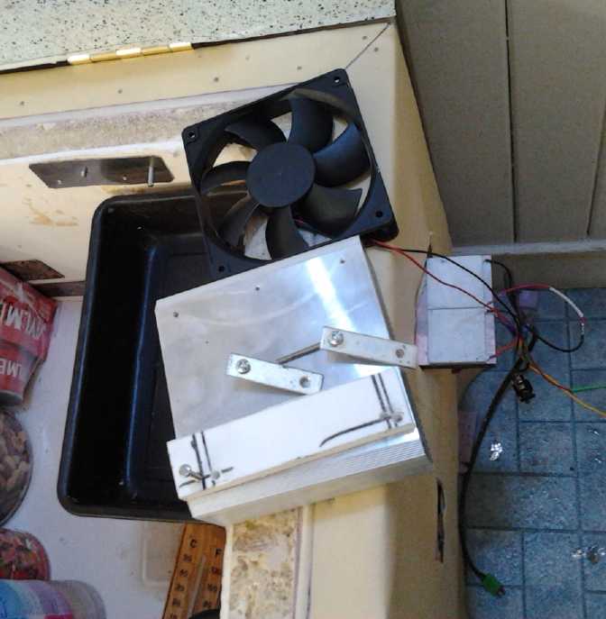
I wanted to try evacuated tubes or thermosiphoning water
with radiator fins for a totally silent fridge. But I also wanted to
get it running and try out the two peltiers in series idea without a
big diversion. So I used the excellent looking new heatsink from
TecTeg.com, and a 120mm square fan from Digikey.
The fridge now has none of the parts from the original
peltier camping cooler I bought when I started. (In fact, I can now
reassemble the cooler for summer camping.) For this fan, I put in a 100
ohm resistor, and turned it over to blow down instead of up, to quiet
it down.
However, the lower heat generation part seemed good,
because the highest temperature reading I could get on the heatsink
side of the peltiers was 23°C, instead of in the low 30's. So as
expected, the two peltiers were pumping from a lower warm side
temperature. (Of course, not only were the series peltiers making less
heat: the fan was blowing more air, it was a better heatsink, and the
kitchen was only 17°.)
After half an hour or so, the aluminum bar going from the
peltiers into the fridge was -3 coming off the peltiers, and +2 under
the pan, where it had cooled a cup or so of water from +7 to +4. Here
were a couple of thermal conduction inefficiencies - one would hope the
warm water's heat would keep the tray and bar warmer, and also that
there wouldn't be so much heat gain - at least five degrees - along the
length of the .5" x 1.75" bar.
According to the graphs, at 3.4 amps and 26°
temperature spread, the peltiers should be pumping about 20 watts each,
for a total of 40. That's as much as a single element at 6.8 amps, even
if the temperature differential was no more.
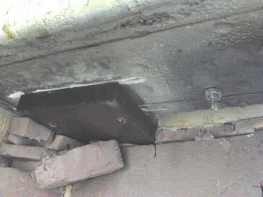
Peltier/outside end of the aluminum bar.
The bar went through the fridge wall and the pan was bolted on inside.
Later that evening, I was less sure about the efficacy of
the system. The voltage was still 12.5 and the amps 3.15 (39
watts), but temperatures seemed almost static. The warm side heat sink
was just
21-22°C. There was frost on the "cold transfer bar" towards the
source end and it was still -4 or -5°C coming off the peltiers. The
fridge
had dropped from 6.5° to 5.
Ice had been starting to form earlier in the 1 cup of water I had
initially put in, but after adding another 3 or 4 cups at 5 or 6 PM, by
9:30 there was still no ice. I went to bed late, but there was still
only a little ice. Was I reading the graphs wrong? I turned it off
anyway, and by morning the fridge was up to 9°.
The next morning, before trying to get onto the battery
project, I decided to cut the hole through the fridge wall bigger and
clamp another .5" x 1.75" aluminum cold conducting bar under the
existing one to improve the coldness flow from the peltiers to the
water tray. This seemed better, with the warm side pushed up to 26°
but the cold side not getting so cold. It was 1° going into the
fridge (where the water was 12). But then I managed to get the probe
right behind the peltiers. It read -6, just 3" away from +1 on the same
thick bar!
When aluminum isn't aluminum!
At this point, I was pretty sure I had some aluminum alloy
bar instead of pure aluminum, and that that was the chief problem with
the whole unit. It was gaining at least 5° in the first 3" and
3° in the next 3", headed for 10° from one end to the other. So
instead of 25°, the temperature spread across the peltiers was
perhaps 35°, and there'd have been, as observed, not much heat
pumping wih the lower currents. Was that what came of buying aluminum
at a
scrap place... or would brand new "aluminum" stock be likewise impure?
I found out the next day, the 12th. Almost all "aluminum"
sold is actually one alloy or another, made to machine more easily and
be stronger. Any alloy (elaborate superconductive combos
excepted) is much less conductive of electricity and heat than the pure
element. This was doubtless why my "aluminum" heat transfer rod for the
heat pump didn't seem to work very well either, which led me directly
to the copper pipe and water/anti-freeze convection based idea. For the
motor
controllers and other heat sink items, distances are short and alloy is
"good enough". The real thing would be better in all cases.
It then occurred to me that my "copper", which I've also
purchased for copper's great electrical and thermal conductance, might
have the same problem. So I thought I'd also have to view plumbing
pipe, rod, plate and other sources of "copper" with suspicion despite
their high cost, but I've been assured that copper is usually pretty
pure.
Otherwise it's considered to be some variety of "brass", "bronze" or
whatever. And the color is noticably different.
I did some phoning around on the 13th. I could look on the
web, but it started to sound like pure aluminum bars or plate wouldn't
be an easy thing to get hold of. Trying to melt down aluminum wire or
pure aluminum "1050" or "1100" sheet to try and make a bar had little
appeal. I decided I'd just have to redesign the unit with the shortest,
fattest alloy bar I could find. Or a copper bar, but that would be
heavy and costly. Gee, putting everything in line on one bar seemed so
simple!
After spending two
days on the fridge instead of a couple
of hours, I was a bit fed up with it. I meant to leave it, working and
at lower power, but having to run considerably longer hours to freeze
ice instead of about the same (or wishfully, shorter). But a short,
pricey copper plate
heat conduction
arrangement started to sound like an appealing way to quickly solve the
problem, and on the 15th I went down to
Smith Bros Foundry to see what they had. I ended up with a 3" x .5"
copper bar, 9" long. That was just a bit too narrow to mount 2 40mm
square peltiers
side
by side. Annealing it with a torch and pounding one end to 'wide
enough', and then trying to get it perfectly flat again, seemed
daunting. So I found a piece of .25" thick copper plate at home, left
over
from a magnetic torque converter idea. Bolting a .25" x .5" x 2" piece
onto the big bar made it just wide enough, 3.25", to hold both.
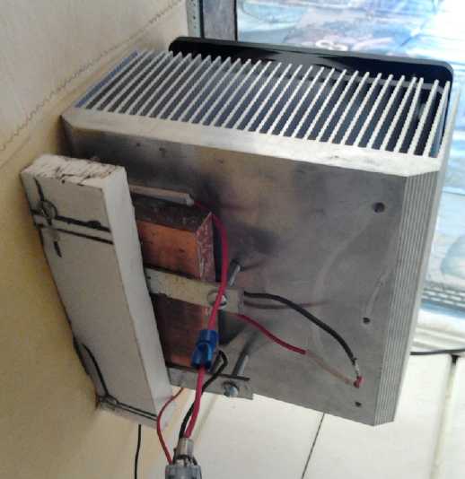
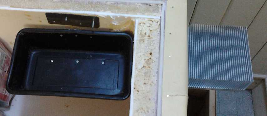
Heatsink with copper bar... I realized after installing that the air
could only vent out one end of the fins.
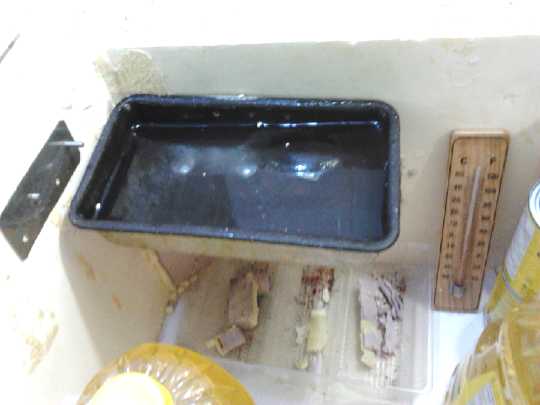
Sideways pan on short copper bar freezing ice.
Pan is now mounted near top for better cold air circulation,
to better keep the whole fridge cooler.
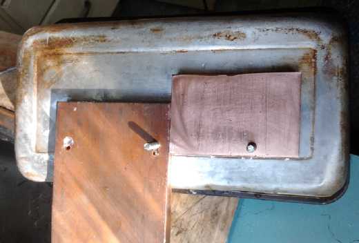
Bottom view showing copper bar sticking in through the wall.
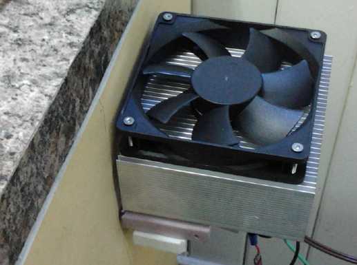
Installing, with ice pan attached to copper bar,
Peltiers sitting on copper bar outside,
and heatsink and fan sitting on wall.
Installed, but showing one peltier sticking out.
In the 17°C kitchen,
the warm side stayed down at
23° with -3° on the cold side feeding the tray of ice-water - a
peltier temperature differential of just 26° or so and only about a
3 or 4 degree gain along the copper and into the tray. The current
stayed at 3 to 3.2 amps. This all seemed excellent. But it didn't seem
to freeze the water much faster than with the aluminum.
I realized at some point that I could easily disconnect
one peltier and run full voltage on the other. I decided to try it and
see how well the improved layout worked with just one at 'normal'
power. The fridge drew 6.4 amps instead of 3.2. The warm side
temperature rose to over 30°. Everything seemed good and I waited
to see how fast the ice blob would grow. Instead, much to my surprise,
the frost on the copper bar melted, and it stopped making ice in the
tray. It sat at about the freezing level. I tried the other peltier
instead and
got the same result. The ice that had been made by the two in series
earlier now floated up - it was no longer even frozen to the source of
cold
at the bottom!
It seemed to me there could be just one cause: the
unpowered peltier module was electrically but not thermally removed
from the system. It was conducting the heat from the warm side to the
cold side fast enough to seriously reduce overall system performance.
Here then was demonstrated a major cause of Peltier module
inefficiency: direct heat conduction across the module.
(As a TEG, the unpowered peltier module had about 1.25
volts open circuit, and would supply about an amp if shorted. A bigger
temperature difference would have made more useful electricity.)
Soon I started to realize that when it's turned off, the
fridge must radiate a lot of its cold from the ice tray, along the cold
side bar, through the peltier(s), to the warm side heatsink, and thence
to the air in the room. This would negate the efficacy of a
considerable portion of the excellent foam insulation, and it was
considerably worse with two peltiers.
An evacuated tube with water in the bottom radiator would
not only eliminate the fan noise, but much of this unwanted loss of
coldness as well, since only heat and not cold would transfer up the
pipe and radiate off - the "heat diode" effect. This devide is covered
in its own topic section, below.
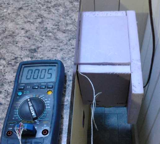
After discovering how much heat was transferring across the peltier
modules when they were off,
I made a foam box to cover the entire cooling unit.
Sure enough, the temperature in the box dropped to 5°c, the fridge
temperature. When the fridge was off,
the ice tray coldness was being radiated straight out into the room
from the warm side heatsink!
I set the fridge back to 'two in series' operation. At
least whatever losses were inherent were theoretically accounted for in
the graphs. At midnight there seemed to be enough ice and I turned it
off. There was still a bit the next morning at 10 AM.
On the 17th, the first full day of normal operation, I
noted that ice seemed to be forming reasonably quickly (faster than had
I expected), but the pattern of ice buildup seemed to indicate only a
few good points of connection from the copper bar to the tray. This was
understandable as I was only able to put two of the three bolts into
the copper, since the tray was turned sideways to it for the minimum
bar length. (Did I mention copper is expensive?) So I decided to put a
thinner copper strap from the second to the unused third bolt the next
morning when the second bolt wasn't encased in ice.
When I went to look I found a small piece of 1/2" thick
copper bar left over from another project (magnetic torque converter),
so I used that instead.
Second bar of copper to cool the pan better.
Main conclusions:
* For daytime solar power with over 13 volts, my idea of cooling with
half the current does seem to have worked. The
fridge is now around 40 watts instead of 70, and cools roughly as well
- and the peltiers don't even seem to be making the best contact with
the heatsinks.
* It makes ice somewhat more slowly, but rather than this being caused
by reduced cooling, it appears to be because in the changes, the tray
was moved upwards from about the middle (too low!) to near the top. The
cold air flows better and over the food to the far side, reducing
temperature stratification and keeping the whole fridge a little
cooler. The ice also melts more rapidly overnight, which doubtless has
little to do with the peltiers. (This leads to the thought, tho, that
some heat does conduct across the peltiers... and there are now
two of them instead of one. I wonder what happens if I insulate the
whole cooler section on the outside of the fridge when it's turned off?
or maybe first just measure the warm side heat sink at night and see if
it's substantially below room temperature?)
* A little more current (3.5 to 4.5 amps, not 6 or 7) could freeze the
ice in less time still with good efficiency, allowing the fridge to run
fewer hours during the day, reducing battery storage or grid power
requirements for those short winter days. Perhaps this current could be
obtained with a 15V and an 8V peltier in series instead of two 15V
units. (I obtained the 8V amp unit but didn't find time to try the idea
out in March. The 8V, 8.5A peltier is smaller than the 15V, 8.5A
unit... probably with 8/15ths of the surface area and 8/15ths as many
thermocouples, and so will conduct less heat across when the fridge is
off.)
* The other key to peltier performance besides running the peltiers at
lower
powers is to minimize the temperature spread between
the warm and cold sides of the unit. This is accomplished by good
thermal contact to the faces of the peltiers, and by the most
effective possible heat transfer and dissipation.
* A really good heatsink and adequate
fan,
along with the lower power of the series peltiers, does a very good job
of keeping the warm side cool, only 5 or 6° above room temperature.
Turning the fan down to where it's pretty quiet added a couple of
degrees to that.
* On the cold side, a .5" x 1.75" aluminum alloy bar didn't conduct
heat as
well as one might wish, and the 18" length much compounded the problem.
It was gaining about 8° from one end to the
other, and that shows up as greater temperature differential across the
peltiers (colder cold side), reducing efficiency and heat pumping
watts. The shorter the
better, and 1" x 1.75"
might be a better size. (It needs to be ~1.625" wide to cover a
peltier element.) Pure aluminum would have conducted heat better
than
aluminum alloy, but it seems hard to find. Copper works even better,
and so does making it wider and keeping the length down to 9".
Temperature spread along the copper dropped to about 3°.
* Better Peltier Modules must surely be possible. It would seem that
the glaring cause of their inefficiency is direct conduction of heat
from one side to the other, whether it's powered or not. I can't
readily visualize a markedly better construction myself and I'm no
expert, but perhaps they could at least be made thicker with longer
bismuth telluride thermocouples so that the heat has to traverse
farther and through more material to cross over - and even a whiff of
foam insulation inside could do something more than the air gaps I can
see from the sides.
So I'm going to guess that improved Peltiers will be
created in the not distant future even if no better junction material
than doped bismuth telluride is found, and perhaps make thermoelectric
the new standard heat pumping technology. Having the most effective
products now should put Turquoise Energy ahead of the game when and if
the COP suddenly goes up and attracts more interest.
If the solar/low voltage house wiring system had 24
volts instead of or in addition to 12, I could try 3 of the 12 volt
peltiers in series at 8 volts each. That
should provide at least 40 watts of cooling power. Power consumption
would actually be increased, say 2/3 the current at double the voltage,
but the fridge would run fewer hours per day. In fact, in winter when
the days are shorter, that would be a good plus for minimizing battery
use in a solar powered system.
Evacuated Steam
Tubes for heat dissipation/radiation
These
are
evacuated
pipes
with radiator fins, placed at an angle, with a little
water in the bottom. If the water is heated even slightly, more of it
boils until the steam pressure equals the pressure where water boils at
the new temperature. As the steam travels up the tube, it warms the
radiator fins and cools. When it cools, it condenses back into water
and runs back to the bottom. The change from water to steam "instantly"
removes heat from the bottom, the steam travels almost instantly up the
tube, and the change from steam back to water "instantly" releases the
heat to the fins. Thus any heat at the bottom is "instantly"
transferred up the tube and to the fins, thousands of times faster than
simple heat conduction through solid copper or aluminum. Used in
another way, coldness at the top of the tube will condense steam there,
which will run down and cool the fins. More steam to replace it will
come off the water at the bottom, cooling the water, so coldness will
be transmitted down
the tube.
Heat can go up, and coldness can go down. However,
coldness at the bottom generates no steam, and warmness at the top
merely rarifies the steam up there a bit, so cold doesn't transfer up
to
the fins and heat doesn't transfer down.
These "heat diodes" have great potential as superb
radiators, both for
refrigerators and for space heat pumps. No circulating pump is
required, and with enough fins no fan is needed. The only sounds are
"pinging" noises as the water boils, and even those should be almost
absent if everything is optimized.
In order to work
properly, the vacuum must be complete enough that the water boils at
the temperatures of usage, and of course regardless of vacuum the steam
heat transfer function ceases if the water freezes, at about 0°c.
(In order to reduce both these problems to trivial, I plan to try using
water with ammonia next. Ammonia lowers both the boiling and the
freezing point.)
I hadn't been successful making evacuated tubes containing water last
month, so I invited over Ian Soutar, who had worked with them and made
them in the solar
industry in the 1970's, and told me about them. There were
a couple of little problems like used pipes that we didn't get clean
enough and we still didn't quite get there, but I
got a clearer idea of the details. One
annoying feature was the crimping of the tubes: every time it didn't
work, the end had to be cut off the pipe and done over again.
There was
a second problem with that: I wanted to put aluminum heat radiation
fins on the pipes, and the exact friction-fit holes wouldn't fit over
the
crimped ends. The fins also couldn't be put on beforehand, as they
prevented heating the pipe to boiling, radiating off the heat from the
torch and
causing the steam to condense back into water before it reached the top
end. (This is of course exactly their intended function.)
So I decided on a new strategy: the top end would have a
screw
fitting, and an end plug would screw into it. The bottom end would have
an exact 5/8" disk of copper, silver soldered onto it. This would then
be sanded down flush or better, until the fins would slide over it.
If it didn't work, the plug could simply be loosened and
the attempt repeated. The first pipe (on the evening of Saturday the
23rd) was a makeshift (with an odd fitting I had lying around) on the
plug end. It might have worked if the plug had been done up tighter - I
could hear it sucking air.
The second pipe, made with a new threaded end fitting and threaded
plug, seemed to work at first, but soon it also started leaking. This
leak was a small bit missing from the copper disk and a gap at
that point in the silver solder. I redid the solder, loosened the plug,
and tried again. This time it held. You can tell when it's evacuated by
holding it upright and shaking it: the (30cc of) water inside sounds
like a piece of metal hitting the bottom of the (~3 foot) pipe. Ian
thought from the sound that I had a very good vacuum.
I put it in a cup of hot water. I thought the heat was
supposed to spread throughout the tube at once, but although I heard
some 'clanky' boiling noises, the top end stayed cold and the lowest
fins could easily have heated through direct copper conduction.
However, I spent a day and drilled a 5/8" hole at an angle in a split
aluminum block, put it in like a giant "furry" moth's antenna, and
installed the unit on the peltier modules on the fridge.
It seemed to get up to over 35°c before anything
happened, then it would clank some as the water started to boil. The
aluminum block got up to almost
50, and so the cold side of the peltiers stayed at about room
temperature.
I had to remove it and put back the heatsink and fan.
The theory seems good but evidently it didn't have enough
vacuum. This table says
that to boil in the upper 30's celsius, it was probably around 1 PSI
(.07 bars). I needed to get it at least under 1/2 PSI (.03 bars)
maximum to have it boil
at room temperature.
BTW the bottom end of the table says that 175 PSI is
needed to raise the boiling point to 190ºc for the woodstove
electric generator TEG's.
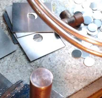
Flush copper end piece silver soldered to pipe
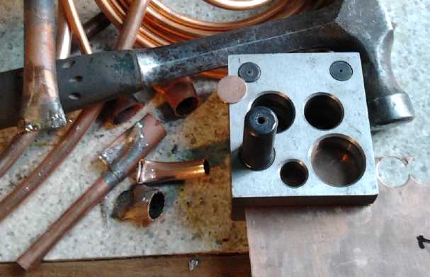
Discarded crimped pipe ends from failed evacuation attempts;
The 5/8" punch for copper ends
(and for the aluminum fin center holes)
Water – Pressure and Boiling Point
Pressure Boiling Point
psi kPa bar degF degC
.09 .6 .006 32 0 (where ice goes straight to steam, Mars)
.16 1.1 .011 50 10
0.5 3.45 0.0345 79.6 26.4 (minimum vacuum for fridge)
1 6.90 0.069 102 38.7
2 13.79 0.138 126 52.2
3 20.69 0.207 141 60.8
4 27.58 0.276 153 67.2
5 34.48 0.345 162 72.3 (Mt. Everest)
10 68.95 0.689 193 89.6
14.69 101.3 1.01 212 100 (Sea level)
15 103.4 1.03 213 101
20 137.9 1.38 228 109
30 206.9 2.07 250 121
40 275.8 2.76 267 131
50 344.8 3.45 281 138
60 413.7 4.14 293 145
70 482.7 4.83 303 151
80 551.6 5.52 312 156
90 620.6 6.21 320 160
100 689.5 6.89 328 164
110 758.5 7.58 335 168
120 827.4 8.27 341 172
150 1034 10.3 359 181
175 1207 12.1 372 189 (TEG2 max temperature)
200 1379 13.8 382 194
225 1551 15.5 392 200
It wasn't until April that I bought some "household
ammonia". In this aqueous solution, some of the ammonia converts to
ammonium hydroxide (NH4OH... dissolved NH4+ OH- ions. I'm not sure how
that fits with the life liquid theory.) On none of the product I looked
at was the strength specified. If I wanted actual ammonia (NH3), I'd
have to order it at a welding supply place. However, since I don't
really want to handle the anhydrous gas, I decided to try some grocery
store product and I'll see how it works.
Electricity Storage - Turquoise Battery Project (etc.)
Decreasing Self Discharge?
I go on and on about self discharge, and indeed it's been
a problem. However as things progress it's gone from minutes in early
experiments (with other chemistries?) to overnight. The fact that the
latest Mn-Mn cell charges to over 2.5 volts where the earlier cells
seemed to be less - 2.2 to 2.4 volts - actually indicates that those
earlier cells probably had too much self discharge to maintain that
charge voltage very long so I dismissed the dropping readings, where
'Production Prototype #2' holds it for
some time, and can supply a 50 ohm load at over 2.4 volts (over 48mA)
for a minute or two.
New Electrode Compactor
On the 10th or 11th I made a new
compactor from a piece of 3/8" stainless steel plate. With such
thickness of walls, I think my days of bulging, non-flat electrodes are
over. I made the side pieces from 3.15mm thick sheet/plate for 3.15mm
thick
electrodes. On the 17th I made some 2.3mm sides for thinner negodes -
actually I re-used the old sides just by drilling some new holes in
them.
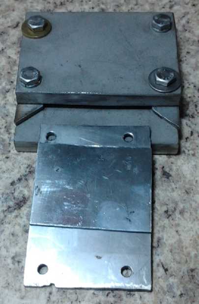
New electrode compactor
After polishing insides
Compacting powder to form an electrode.
The electrodes are done in several small fills and compactions
until the space is almost full, at which point they're about 64 x 64mm.
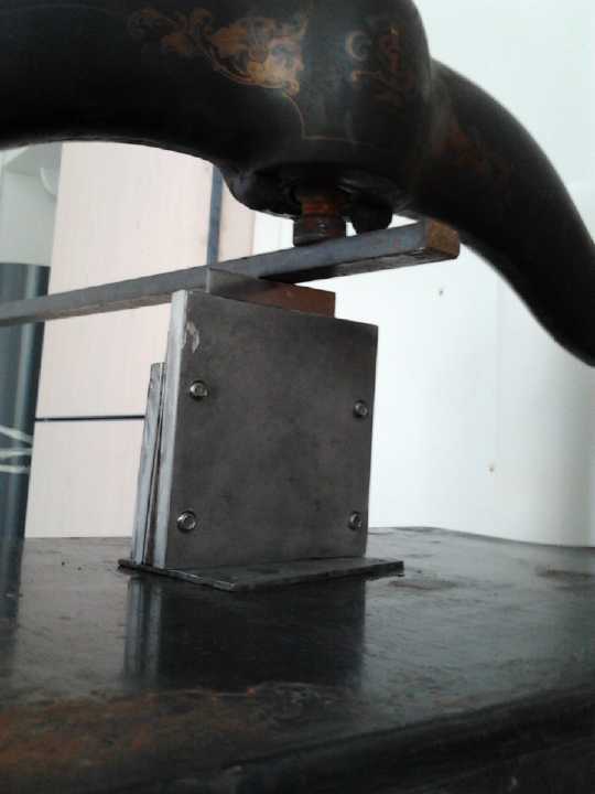
Rear view.
With the book press setting the fulcrum height, a steel pry bar is used
to push down like an arbor press.
(The twisting screw on the book press tends to push the die aside,
and turning the handle takes longer than prying down.)
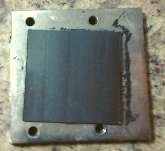
A compacted electrode with front & sides unbolted from compactor
It is my habit to lie in bed a while after I wake up, and
let my thoughts drift to various things. Perhaps it's a bit of a
substitute for daily meditation. Often I rise with a new idea of how to
make something or solve some problem.
Clamping together cell #2 while gluing, and the heat glue
around the terminal slots, seemed to have prevented external leaks
(except through the filler hole). The paper and the plastic basin 3D
printed into the case design, with the upper basket glued over it,
should surely have prevented any leaks from the posode.
But when I had shaken out the electrolyte and replaced it,
a quantity of powder had also come out, and thereafter the overnight
self discharge was higher instead of lower. Surely this internal powder
leak had to be from the negode. It seemed most likely that even with
the zinc sheet pressed against the basket - perhaps not very firmly, as
the disassembly of cell #1 had shown - stuff had come out the join
between them. It also seemed most likely after that that the self
discharge was from crap between the electrodes rather than (or -
hopefully not - in addition to) chemical causes.
On the morning of the 8th, I finally figured out how to
prevent the negative side from leaking powder. If the top edge of the
basket holding it was extended up
to the front wall of the cell, it could be sanded flush with it, and
glued to it as part of gluing the front on the cell. A small slot for
the zinc current collector terminal would be included on one side.
Provided that slot had no extra space around it (which might, if
necessary, be achieved with wax or a soft sheet - thick paper?) there'd
be nowhere left for the materials to potentially escape.
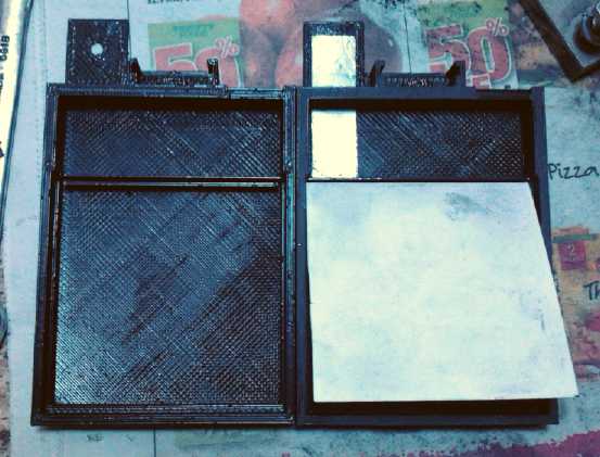
To keep positive side from leaking powder,
there's a rim around the bottom and sides,
and the paper folds into a slot at the top.
Slot on left came out too narrow to fit the paper in.
The one on the right worked well.
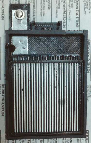
The center basket holds the lower paper in place.
The vertical bars form a thin space between electrodes for gas bubbles
to rise.
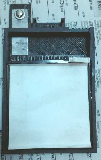
A second watercolor paper, folded up at top and bottom (where the 3D
printer couldn't make a proper rim),
holds in any loose negative electrode powder materials.
The new feature in #3 is the plastic at the top of the basket being
made flush with the case front, to be glued to it.
Only at the right (where the fold of paper is) is a gap necessary for
the zinc foil terminal to exit to the top.
Negode in place, perforated zinc goes on top of it, hopefully making
good contact at many points.
Zinc foil on, the cell is ready to be glued shut
The cell is clamped together while the methylene chloride solvent glue
'sets'
Battery after a couple of weeks. Crystal growths probably indicate a
small leak at positive terminal.
There's a little white salt on the glass marble covering the filler
hole, but nothing like colored crystals.
I had already put in the roughened (wire brushed) graphite
sheet, painted with osmium doped acetaldehyde. On the 12th I mixed
powders for 100 grams of posode material:
45g Potassium permanganate
18g Nickel hydroxide
36g Graphite powder
2.5g Samarium oxide
To 30 grams of this I added a bit of dishsoap ("Lemon
Fresh Sunlight" with the sulfates & sulfonates to chelate the
permanganate) and enough Diesel Kleen (has methyl benzene to dissolve
the graphite powder) to wet it, and started filling the compactor.
The electrode took about 24-25 grams of the powders, since 6 were left
over.
Without stopping to figure it out (given past
disappointing results), that should be quite a few amp-hours worth if
everything works.
When I put it in, even 3mm wasn't
thick enough for the space now reserved in the case for it. I inserted
an extra piece of flexible graphite behind the 'real' one to occupy
some space.
Resistances measured
around 50 ohms between any two points on the surface, or 25 ohms from
the surface to the flexible graphite terminal. A day later, after most
of the Diesel Kleen had evaporated and left the graphite more
conductive, it was down to 30 and 15. I installed the stainless steel
terminal bolt, washer and nut, and from electrode surface points to
there was just around 12 ohms. This seemed very good. If it didn't lose
conductivity inside the cell when electrolyte was added, any
conductivity problem must be with the minus side. I probably added more
graphite than needed, but I'd rather have more conductivity than less.
Graphite Dissolving Experiment
Finding the lowered resistance of the electrode gave the
thought of an experiment: What would compacting pure graphite powder
wetted with Diesel Kleen give? I did it to find out. The result seemed
more or
less like most electrodes, easily cracked and crumbled, but with just a
few
ohms point to point.
Then the Middle Stuff and the Basket
I hooked the paper into the slot at the top of the
posode's box and folded it down. This worked well.
With the 3D printer still acting up, I glued in one of the
old baskets, and made a thin 'toothpick' of plastic and glued it in. It
ended pretty flush with the case edge.
I cut the top paper and then painted the bottom (outside
side) with zirconium silicate. Perhaps that will reduce self discharge?
Then the Negode
I don't really understand why even a pure Mn/Mn(OH)2
electrode wouldn't be highly conductive, at least when well charged,
and
the zinc powder should only improve it. But obviously my cells have
been much less conductive than expected, and the resistance readings
certainly make the negode the suspect. So I modified the mix a little
to see if there would be any notable improvement.
I took 65g of the previous mix (MnO2 50wt%, fine Mn powder
30%, fine Zn flakes 20%, Sb2S3 powder 1.2%) - and added 5g of fine zinc
powder (not flakes), 3.5g of coarse granular Mn (#60 mesh), and 1g of
VeeGum (a bentonite clay mix, described in a much earlier TE News).
That made it about 75g, and the exact proportions should be calculable.
The zinc powder should generally make the mix more
conductive, the Mn granules should carry low resistance across from one
point to another, and the VeeGum should help solidify the entire
electrode physically.
I compacted in almost exactly 1/2 the mix, 37.5g. I didn't
think to check the resistance until after I'd dried it in the oven. I
was shocked - it was in the low megohms even with all the zinc. Then I
realized that the MnO2, with the mixing water, could well have oxidized
all the zinc. [along the lines of: Zn + MnO2 + HOH => ZnO + Mn(OH)2.
Also the Mn metal particles.] Torching it brought little change to the
readings. Once again I'm left with hoping it improves as the cell
charges. I think I'll put the charge on as soon as I fill the cell, or
even in advance of filling it, to minimize oxidation of the zinc
current collector.
To fit it in the basket, I had to scrape off a bit of one
side. It was much harder scraping than usual. The VeeGum must be doing
its job!
I placed this in the basket and pressed down, breaking it
into several pieces because it
had warped. (It was no harder
than usual in that respect!) I think it lost moisture unevenly and
cupped in the oven because it was sitting on the impervious stainless
steel. I'll set it right on the firebrick next time.
Then
I put the zinc collector sheet on top. This time, instead of having
extra space, it stuck out the top some. It was going to take a lot of
pressure to glue the front face onto the cell! But the spikey points in
the collector sheet would be well dug into the electrode. Next time I
think I should make '+' side nearly a millimeter thicker, and the '-'
side a millimeter thinner. As well as filling the spaces evenly as
designed, this would even out the amount of active material in each
electrode.
Gluing the cell together
The big question was could it be glued together not to
leak, or would the overstuffed box force cracks open? I tried to get in
lots of methylene chloride, and clamped it tightly with stainless steel
plates and 4 C-clamps. I left it for several hours to be sure the
plastic was as hard as it could be. When I undid the clamps, a corner
popped open. That was that for that for a couple of days.
On the 17th I made thinner side plates for the compactor,
2.3mm instead of 3.15. Then I made a thinner electrode, which used
about 28g of mix.
For compacting, I got a steel bar from the garage and used
it as a lever within the book press frame. Essentially, I had an arbor
press, with the book press screw for a lever height adjustment. This
was
easier to use.
After torching the 'trode I slid it in... forgetting once
again to check the resistance first. This time, there seemed to be
almost too much space, that as with #1 and #2, the zinc sheet wouldn't
be pressed very hard against the electrode. But it was much closer and
I glued the case together and clamped it, regardless. It didn't leak.
Testing
I filled the cell on the evening of the 17th, with a 9mA
charge already connected to try to minimize further oxidation of the
negode materials and zinc current collector. Thus it started almost at
once at over 2 volts and it seemed to do much less percolating when
filled
with 25cc of pure KCl (s.g. 1.175) electrolyte. After 3 hours I raised
it to 15mA. Later that went to 30.
I think it was a good plan because the percolation was
occasional after a couple of hours, and at no time was there any
bubbling, frothing or electrolyte coming out the filler hole. Of
course, the composition was slightly different too, with extra zinc and
the granular manganese.
Performance was again poor, but on the first discharge
test - 50 ohms or mostly over 40mA, the cell ran 80 minutes, twice as
long as the best time of cell #2. And it generally held higher voltages
with a given load resistance.
When the initial brownish electrolyte with some powder was
dumped and shaken out, subsequent shakings gave only clear water,
seeming to indicate no internal powder leaks.
For a week or more the voltages were generally lower. It
took more
current to reach a given voltage when on charge. It was probably all a
result of higher self discharge. The zirconium silicate 'paint' on the
separator paper evidently wasn't doing much. Things started to improve
with continued charging, but overnight self discharge is the one thing
still making the cells impractical for most any use.
The 'trodes were 6.4x6.4cm or 41sq.cm. At 50mA/sq.cm,
that should be 2 amps without serious voltage drop, but it was 1/10th
of that. I started to wonder if maybe I shouldn't try graphite as a
conductivity additive in the negode again, instead of zinc powder,
which didn't seem to be much help. I had attributed self discharge to
graphite earlier, but if it had the self discharge without any
graphite,
perhaps that was unwarranted. Two overvoltage tables gave "graphite"
and "artificial graphite", with quite different hydrogen overvoltages,
one of
which might have been okay. I decided making cell #4 was in order even
while testing #3, and it would have graphite.
Meanwhile #3 was on some low charge most of the rest of
the month - and it did improve. The voltage at any given rate started
to rise and it held voltage better under short loads. On the 29th I did
another long 50 ohm load test, and it ran for 2-1/2 hours - over twice
as long as the first time, 4 times as long as cell #2, and delivering
over .1 amp-hours mostly at over 2 volts. A one ohm load started at
over a volt and delivered over .8 volts after 10 seconds. If keeps
improving like that for a few more months, it might be a really good
battery. On the 31st it was marginally better again. Interestingly, the
pH, which I hadn't tested in quite some time, had dropped to about 9 or
10. That's still in the right range, and it explains the voltage rising
from around 2.5 to 2.55.
It may be that it takes quite a long time to reduce a good
portion of the zinc and sufficient manganese to establish good
conductive pathways through the negode. I don't see why it should, but
it does start off very poorly conductive, and there's always
individualistic features and characteristics with any battery
chemistry and formula,
and no one has had the experience to be familiar with them for Mn-Mn.
A side note on cell #3 is that orange crystals started
forming on the graphite positive terminal. This means (a) the crystals
aren't ferrous oxide from the rusting ball bearing used in the cell cap
of #1 and #2, and (b) There must be a leak at the graphite terminal
letting liquid up. Probably it's a gap in the heat glue. Otherwise, it
must be wicking through the graphite itself. But it can't
be a big leak since I only added fluid once or twice, not long after it
was made.
http://www.TurquoiseEnergy.com
Victoria BC