Turquoise
Energy Ltd. News #63
Victoria BC
Copyright 2013 Craig Carmichael - May 6th, 2013
www.TurquoiseEnergy.com
= www.ElectricCaik.com
= www.ElectricHubcap.com
= www.ElectricWeel.com
Features: - NiMH Compact, stackable 12V D
cell battery cases (12V, 10AH per case) - CAT standard click-lock 12V
plugs & sockets
Month In Brief
(Project Summaries)
- CAT Standard click-lock plugs & sockets - Getting the Mazda RX7
& renewed batteries going - Compact, stackable, 12 volt NiMH "D"
cell battery cases with 3D printer - Programming microcontrollers -
Fridge
In Passing (Miscellaneous
topics, editorial comments & opinionated rants)
- Investing in the future - "Cold fusion" (catalytic fusion) evidently
works, was suppressed... by universities, MIT.
Electric Transport - Electric Hubcap Motor
Systems
* Getting the Mazda RX7 going
* Superior battery charging and automatic battery monitoring
* Ungrounded "floating" high voltages are less hazardous
Other "Green" Electric Equipment Projects
* Fridge: 15v + 8v Peltier modules in series for more efficient and
effective operation
* Getting Started with TI MSP430 microcontroller (µC, uC)
software
development (under Ubuntu): µC controls are wanted for fridge,
heat
pump, EV
battery monitoring, motor controller overcontrol, and still other
projects
Electricity Generating (no reports)
Electricity Storage - Turquoise
Battery Project etc.
* Lead-acid Battery Renewal with Sodium Sulfate - New Techniques
* NiMH compact, stackable 12V battery cases for making large
batteries from D cells (first one is 12V, 60 AH for electric RX7) -
a more compact alternative where "handy battery sticks" don't fit well.
* "Super battery stick" proves less than super.
No Project Reports on: DSSC
solar cells, LED Lighting, Pulsejet steel
plate cutter, Magnetic
Motion Machine, Ultra efficient vehicle transmission/torque converter,
CNC Gardening/Farming Machine (sigh, maybe summer 2014!),
Woodstove Electricity Generator, Peltier heat pump, Turquoise (MnMn)
battery.
Newsletters
Index/Highlights: http://www.TurquoiseEnergy.com/news/index.html
Construction Manuals and information:
-
Electric Hubcap Motor - Turquoise Motor
Controller - 36 Volt Electric
Fan-Heater (say, this heater is now obsolete! Use Peltier module heat
pump!)
- Nanocrystalline glaze to enhance Solar
Cell performance - Ersatz 'powder coating' home process for
protecting/painting metal
Products Catalog:
- Electric Hubcap Motor Kit - also please inquire about Electric
Caik
3KW Motor Kit
- Sodium Sulfate - Lead-Acid battery longevity/renewal
- NiMH Handy Battery Sticks & Dry Cells (cheapest NiMH
prices in Victoria BC)
- LED Light Fixtures
Now accepting BITCOIN
...all at: http://www.TurquoiseEnergy.com/
(orders: e-mail craig@saers.com)
April in Brief
Having bought the 1981
Mazda RX7
electric converted car, R & D priorities shifted to making it work,
as I intended with "any old mix of batteries" to reduce costs and not
waste good batteries. I didn't want to pour thousands
of dollars into this old car, but I could certainly spend a week
or two renewing PbPb
batteries to get it back on the road. Two of them didn't
work out and I traded
them for another, and a couple more didn't seem to perform well, so by
month's end I had
spent a considerable amount of time on them.
AGO Environmental had
a big splurge of orders and the owner Jim Harrington (who sold me the
RX7 for irresistible terms) asked if I could work there for a few days,
wiring cables for motor controller devices. I did, which naturally ate
away at my own project time.
Other than the Mazda, which I chipped away at (cleanup
&
minor adjustments, chargers, windshield wipers, LED light bulbs and the
batteries), projects got neglected owing to lack of time. Up to the
22nd, I didn't find even
bits of time to do much of anything including Turquoise Energy's income
tax, which should have been done in March. The thermoelectric projects
other than trying
another peltier configuration on the fridge were pushed aside,
perhaps for the summer, and MnMn battery test
cell #4 didn't get made. On the other hand, some previously neglected
items came
to the fore and got done: click-lock CAT Standard 12 volt plugs &
sockets,
and the
3D printed cases to make large capacity compact, stackable, 12V NiMH D
cell batteries.
The "Edible Everything Landscaping" [goedible.com] person
who wanted the
electronic soil moisture probe switch (no point watering if it's
rained) came back as gardening season
approached, and put the parts on the PCB. After we did a bit of
troubleshooting and found his several cold solder joints, it worked to
his satisfaction.
This was gratifying.
Here are the schematic and the PCB layout, done in Eagle PCB.
I've been saying my Electric Hubcap motors seem like
they're around 95% peak efficiency. But I haven't
definitively tested them, and probably many people think I must be
overestimating. But this month I see a company claiming their new
motors are 97% peak efficiency. They also claim an amazing 2600 W per
Kg, which make the Electric Caik's ~400 W/Kg
and the Electric Hubcap's ~300 seem pretty pale, tho these figures are
themselves quite good and would
doubtless be much higher for short bursts of power.
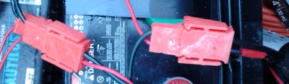
Click-Lock CAT Standard 12V Plugs & Sockets
In order to connect up the individual 12 volt chargers to
each
battery in the Mazda, I created "click-lock" CAT standard sockets and
plugs to put
on each battery and charger. I had had these in mind for quite a while,
and
now that I needed them I designed and 3D printed them. To my surprise,
the design and a $1.50 each price quickly made them popular - I sold a
couple of sets to one person I showed them to, and traded 3 more to
someone else for other trinkets. Yellow was definitely the popular
color.
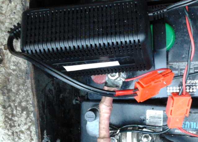
CAT click-lock sockets on batteries and plugs on 13.9V, 5A power
adapters/battery chargers, in the RX7.
Half the batteries have two sockets: the second is for the battery
monitoring system, yet to be made.
I had been putting the CAT plugs' blade folding tool in a vise.
This time I asked myself why not use it freehand? Sure enough it's
easier.
Mazda, Mixed Batteries & Battery Renewal
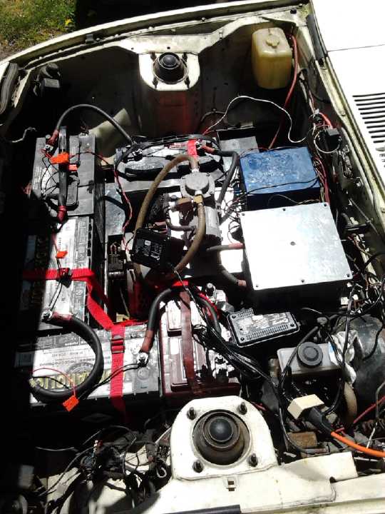
Under the RX7 hood: batteries, main breaker box (grey/silver)
with
"kill" lever by steering wheel, DC to DC converter provides
12 volts, a
couple of dangling 'click-lock' power adapter chargers,
and the front end of the motor just
visible below.
 Talking on the
VEVA electric car list I learned that the
problems
with using mixed batteries extend not only to the need to charge them
individually, but to monitor them individually as well, so the weaker
or lower capacity batteries - or if a charger quits working - don't get
overdischarged or even driven into reverse charge (and hence weakened
or damaged) before the driver
notices. A gauge to show the overall voltage is insufficient,
especially in a typical higher voltage system.
Talking on the
VEVA electric car list I learned that the
problems
with using mixed batteries extend not only to the need to charge them
individually, but to monitor them individually as well, so the weaker
or lower capacity batteries - or if a charger quits working - don't get
overdischarged or even driven into reverse charge (and hence weakened
or damaged) before the driver
notices. A gauge to show the overall voltage is insufficient,
especially in a typical higher voltage system.
In order to not impose such a difficult task on the driver
while
he's driving, I decided it would have to be an automatic
microcontroller based monitoring system that would alert the driver
when any battery started getting low (yellow alert), and then again
(red alert) when it was definitely time to stop. The alerts would also
say which battery(s) it was. Or maybe colored bar graphs (green,
yellow, red) showing all the batteries at once.
This, with 12 volt chargers, should make it much more
practical for
EV owners to buy batteries on an as-needed basis instead of doing bulk
replacements costing several thousand dollars at a crack and
doubtlessly wasting batteries that still have good life in them. So,
unexpectedly, taking on the "mundane" already converted car has led to
yet another new innovative product idea!
Various battery issues and an unknown wire held up running
the Mazda until the 16th, when I got it to move up and down Jim's
driveway. After borrowing a couple more batteries and putting them in
as well as buying license plates and insurance, I drove it the short
distance home on the
17th, where I could wash it and start attending to the many minor
problems of an old vehicle that had been sitting unused for some time.
I also had to convert a bunch more 12V, 5A power adapters from 12.0 to
13.8 or 13.9V for
use as battery float chargers for each battery in the car.
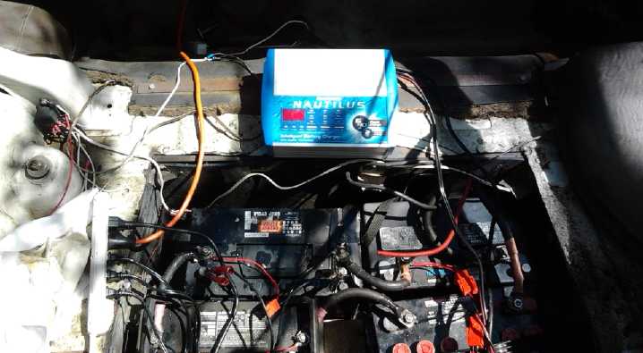
In the rear end of the Mazda. (Plastic & carpet stripped out for
washing.
It came without a rear seat - instead the black hole at the top.) 3
power adapter
chargers are unseen behind the batteries and one regular charger is
employed.
The battery well was installed where the spare tire, and perhaps the
gas tank,
used to sit. (If there's a spare tire, I haven't found it yet.)
After this procedure, the batteries would jump to 14.4
volts when the charger was connected without drawing much current. I
did some higher voltage short pulses with the "charge/start" switch on
the charger, which would probably overpower little differences between
cells. Finally I tried a "smart" lead-acid charger instead of a "dumb"
one. I generally prefer the predictability of the "dumb" ones, but the
"smart" charger proved its worth for this purpose: it raised the
voltage to well over 15 volts to get the battery to start taking charge.
As a couple of weeks and 3 or 4 test drives and recharges
went by, the renewed batteries in the car went from holding about 11.5
volts to 11.8 and then 12 volts. This seemed promising. While some on
the web say to do about 3 charges and discharges, then they're good to
go, someone told me in person they would take many charge-discharge
cycles to develop good capacity after renewal, which seemed to match my
previous and present experience. The number of
chargers went from 3 (done previously for 36 volt Electric Hubcap
systems) to 5 and I could charge the batteries in two groups, front and
rear, after a drive. But one per battery (9 or 10) will eliminate
plugging,
unplugging and moving things around.
The car had problems other than the batteries. Pressing
the clutch pedal had no effect. With an EV there's no need to use the
clutch to start moving, so for test drives I just stayed in 2nd gear. I
had filled the
empty hydraulic clutch cylinder, but it still didn't work, so I thought
I'd have to bleed it. But with all the electrical equipment above and a
metal guard below, I couldn't reach or even see the lower end of the
line. Finally I thought "most clutch pedals go down farther than this
one." I pressed
it really really hard and suddenly it broke free and dropped to the
floor. The mechanism had simply seized up from sitting too long! (and
with
no fluid.) The clutch worked after that without having to do anything
more.
The battery voltage display never came on, and several
times the car had momentarily cut out as I started
driving, but always started again. Finally it cut out and just wouldn't
go, across the street from my driveway, blocking a side street. Home
was close but uphill. I
said "Well, this
is just great!" to my neighbor who was nearby mowing her front
boulevard. She
got someone else from the house, and just then two joggers came along
and she flagged them down. The five of us pushed the car back into my
driveway. Whew, thanks Kathy!
I found a couple of very loose small wire terminals - one
had fallen off its terminal and the other - from the 'electron pedal'
to
the motor controller - dropped off when I touched it. It was the
culprit. I tightened them
with pliers and put them back on, and the car
didn't cut out any more. The drive battery voltage meter worked for the
next two trips and then cut out again - and I found and fixed yet
another
loose wire.
Near the end of the
month I decided I should put in a couple of batteries made of NiMH D
cells, and I started making cases for them (see below). I figured I
should stack at least 6 banks to replace a
lead-acid in the Mazda to handle the currents - up to about 125 amps
even on
my leisurely
test drives. That would make for 60 amp-hours (and ~500$). Each bank
beyond 6 would
decrease the stress per bank and add driving range, but each bank costs
me around 80$.
Whether I convert the whole car to NiMH's (quickly or
slowly) will depend on how much money I have, how easy or troublesome
it is to renew and maintain the PbPb's, how much I drive the car, and
whether the PbPb's give the sort of driving ranges I need. And if I get
the Sprint running it would have priority since it would give
inherently more range per battery. Still, the car with all NiMHs would
definitely outperform lead-acids and it would lose 200-250 pounds. This
would be all the better as the front springs are nearly bottomed out
with 5 lead-acids under the hood.
Even knowing this is a "regular" electric conversion,
working through a typical lossy automotive transmission, and knowing
what people consider to be adequate power for such vehicle systems, it
still surprises me to see the car using 50 to 125 amps at around 100
volts, 5 to 12.5KW, just to putter down a side street at 30KmPH. (From
what the previous owner says, that sounds typical - in fact,
light-footed.) I'm
just as sure now as I was to start with that substantially better
performance
and hence range is possible (I'll stick with my 1.5x figure). But five
years down the road, I have yet to demonstrate it. Hopefully a clutch
mechanism is the last operative piece that'll get the Sprint going.
When I do, the experiences with the Mazda will help me do
a more streetworthy overall job of the Sprint.
12V NiMH D Cell Battery Cases!
I have to keep reminding people who claim they saw
"Who Killed the Electric Car?" that the batteries that made the EV-1,
RAV4-EV, et al so good were nickel-metal hydride. I don't know how
after that movie the corrupt have waved the magic curtain and somehow
not only prevented the manufacture of large NiMH cells but
made everyone forget they exist, last many years, and perform - and
this in spite of their outstanding performance in hybrids like the
Toyota Prius!
 On the
26th I
redesigned the
12V NiMH D cell battery case I'd
had poor 3D printing results with earlier in order to be easily able to
fit in a 60+ amp-hour NiMH dry cell battery or two in the Mazda instead
of lead-acids, to better
illustrate the potential for mixing batteries. The first 5 hour print
was a success, notwithstanding the inevitable somewhat curled up
corners. I separated the cells within by 3mm
so that if they got hot (serious overcharging or overcurrent) and the
plastic labels/sleeves melted, the
cases wouldn't short together and everything go up in smoke.
On the
26th I
redesigned the
12V NiMH D cell battery case I'd
had poor 3D printing results with earlier in order to be easily able to
fit in a 60+ amp-hour NiMH dry cell battery or two in the Mazda instead
of lead-acids, to better
illustrate the potential for mixing batteries. The first 5 hour print
was a success, notwithstanding the inevitable somewhat curled up
corners. I separated the cells within by 3mm
so that if they got hot (serious overcharging or overcurrent) and the
plastic labels/sleeves melted, the
cases wouldn't short together and everything go up in smoke.
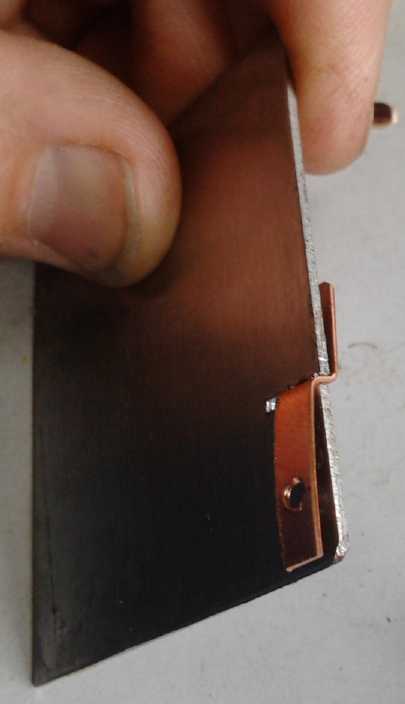
Then I cut the metal bits to connect all the cells (after
which I discovered all the D cells on the shelf very much needed a
recharge). Thick copper is best for the high
currents of an EV drive, and I switched to that from nickel-brass.
Tinned or nickel plated is doubtless best for preventing corrosion.
(Here is an advantage of the battery tubes: no extra connections
between cells.)
 I
made further
improvements and printed more cases in the
next few days. Then I decided that notwithstanding the warped corners I
had a product to add to the Turquoise
Energy Product Catalog, and that the introductory price would be
25$. (Naturally I'd like to make them cheaper and better, but at the
moment, they're a 4.5 hour 3D printout and then the copper bits have to
be
cut and shaped by hand.)
I
made further
improvements and printed more cases in the
next few days. Then I decided that notwithstanding the warped corners I
had a product to add to the Turquoise
Energy Product Catalog, and that the introductory price would be
25$. (Naturally I'd like to make them cheaper and better, but at the
moment, they're a 4.5 hour 3D printout and then the copper bits have to
be
cut and shaped by hand.)
The plastic irrigation pipe first made it possible to make
reliable big NiMH batteries out of D cells. The new case makes such a
battery much more compact, able to fit where a lead-acid battery fits
with space to spare, with lighter weight, better performance, and
much
longer life. ...all at a much higher initial cost, one not dissimilar
to equivalent lithiums.
An attractive idea
in using small NiMH cells (and 13.8 to 13.9 volt float charging) is
that to increase capacity (as in vehicle
driving range), one can add new
batteries incrementally one 10AH bank at a time without removing old
ones - a lower capital investment at any one time - until the
maximum space or weight limit is reached.
6-stack NiMH D cell battery: 12V, 60AH, 180A, 300A intermittent.
The need to program microcontrollers to automate
the
fridge and the heat pump systems, set motor controller RPM limits, and
now for the Mazda battery monitoring
system, led to considering
setting up to do such work, and getting familiar with it, as a
priority.
TI's integrated MSP430 development system took more
computer
hardware than any one computer of mine had, but there was a basic
"MSP430-GCC" C
compiler, utilities, and header data files at the Ubuntu Software
Centre and I used web
searches to help figure out how previously successful people had got
things to work. (...and I started to suspect the majority haven't
succeeded.)
There were some 'non obvious' tricky bits like an obscure
file that had to be placed in an
obscure directory (/etc/udev/rules.d/) to enable USB
communication to the MSP430 Launchpad board, a command
line with specific 'options' to type in to make the compiler
generate the program (msp430-gcc -mmcu=msp430x2553 -o
hello.elf hello.c), and a command
line
'debugger' with another obscure 'option' to run that could erase the
previous program and load the
new finished program to the MSP430 chip on the
Launchpad board. (mspdebug rf2500) Luckily one
person had spelled out these few vital details on his web page. After a
second learning session, I managed to compile, download and run a
couple of programs before midnight (ie before 1AM DST) on the last day
of April.
I'd like to make a graphical program with Python language
so one can just click buttons to get these things to happen instead of
typing them in a terminal program.
Fridge
The two 15 volt peltier modules in series didn't seem to
make ice fast enough to avoid needing considerable evening battery
capacity - and not at all if the power was below about 12.5 volts.
 On the 22nd I put 15 and 8 volt peltiers (both 8.5 amp) in
series to cool the fridge, raising the daytime voltage on the 15 volt
one from about 6.7 to 8.4 volts. The voltage on the 8 volt unit was
then
about 4.8. Both were still in the better efficiency area of their
specs.
Typical daytime current went up from 3.1 amps to 4.0. But the warm side
temperature rose from about 26 to 30 - partly it was the kitchen
warming with the weather. The cold side was -5 making a 35 degree
spread instead of the 30 I had with the 15:15 volt units, and the heat
pumping didn't
seem to increase a whole lot. I raised the speed of the fan, but it
only
lowered the warm side a degree or two. But after a couple of weeks, it
did seem to me there was generally more ice by evening.
On the 22nd I put 15 and 8 volt peltiers (both 8.5 amp) in
series to cool the fridge, raising the daytime voltage on the 15 volt
one from about 6.7 to 8.4 volts. The voltage on the 8 volt unit was
then
about 4.8. Both were still in the better efficiency area of their
specs.
Typical daytime current went up from 3.1 amps to 4.0. But the warm side
temperature rose from about 26 to 30 - partly it was the kitchen
warming with the weather. The cold side was -5 making a 35 degree
spread instead of the 30 I had with the 15:15 volt units, and the heat
pumping didn't
seem to increase a whole lot. I raised the speed of the fan, but it
only
lowered the warm side a degree or two. But after a couple of weeks, it
did seem to me there was generally more ice by evening.
But one thing I noticed in changing the peltiers: I rubbed
at the heatsink compound on the copper bar with the peltiers gone with
my fingers, and rubbed off a small lump or grain of some sort. This may
have been preventing optimal surface contact of one peltier for quite a
while, which might explain why I thought it was working as well as the
single peltier at first, and then I changed my mind and decided it
seemed to make ice too slowly. Now I'll have to try the two 15V
peltiers
configuration again.
Another thing that finally dawned on me was that the ice
was melting faster at night with the new setup, which included the fat
copper
bar and two peltiers to transfer cold from the ice tray to the improved
warm side heatsink, to better dissipate it into the room. With the
first assembly, the ice in the fridge would last 10 or 11 hours but now
it would only last 8 or 9. If I put a foam box over the outer assembly,
it got fridge cold inside, and the ice in the fridge lasted 11 or 12
hours.
The remedy for this, I hope, will be the water-ammonia
evacuated radiators instead of the solid heatsink and fan. The "heat
diode" evacuated radiator has
more advantages than immediately meet the eye. It'll only radiate heat,
not coldness. It can
be well insulated at the bottom end without affecting "ON" heat
radiation along its length, and something close to the 11-12 hour ice
melting figure
should apply.
As May started, night time temperatures rose fast after a
chilly April. I was uncomfortably warm for the first time this year.
The fridge had to work much longer to make any ice, and stay off for
fewer hours at night to keep its cool, in spite of insulated boxes or
anything I'd done with it. Occasionally leaving it on all night became
necessary. (I want that automatic control!) Four inch foam insulation
at least for the top, bottom and back, and an octagon shape, now seem
like even better ideas for minimizing heat gain.
In Passing
Incidental news, editorial comments & opinionated rants
Investing in the Future
The "5 gallon flush" has become the "5 liter flush" these
days,
and the city has continued summer water rationing for no apparent
reason despite building a larger dam. (So just what was the new dam for
then?) As less water is used, the city water rates keep rising to
maintain
revenues - less and less water costs more and more. I replaced my two
old toilets with new low
flush toilets last year.
They cost about 400$. The first four-monthly water bill with them only
(admittedly for winter - no gardening) arrived in April and was around
25$ less than usual - 1/3 off, suggesting a total 75$/year savings. So
at
present
water rates it'll take about 5 years to pay for
them (ignoring my labour installing them). The toilets should of course
last pretty much as long as they're wanted (just as the decades old
ones were still perfectly good) and will continue to save.
Let's see...
if I had put them in in 1981 when I originally redid the plumbing, how
much would I have saved over the years? Of course, I don't think there
were low flush toilets back then.
The case is similar for many home improvements that
gradually pay for themselves, the latest one being the new woodstove
that uses a little less wood. Investing in the future takes a bit of
money and effort, and generally only pays back gradually. But it's
worth it, and the sooner it's done, the
sooner it starts to pay back. And usually it's better for the
environment.
Unfortunately if you're paying over 1000 $/month on a
mortgage, and 300 $/month on property taxes even after you "own" your
house, doing real things that make real differences to Earth's ecology
may seem trivial compared to doing artificial financial things that can
make a big difference to your financial ecology. Along with much else,
this will change when the pyramid scheme global financial system
collapses.
Catalytic Fusion (AKA "Cold Fusion") - suppressed technology?
Someone sent me a link to a documentary about the
so-called cold fusion that got everyone excited about 25 years ago, but
then seemed to "go away" with other labs "unable to duplicate the
results" of the two inventors. It seems this last claim is simply
untrue, and that palladium has been used as a "nuclear catalyst" to
convert heavy
water into helium, tritium and other heavier elements not present
before the reactions - and lots of
heat. ...even in labs which then claimed it didn't work. Perhaps the
alchemists weren't so far off after all - one of the heavier elements
found was silver. How the discoverers hit on the process I don't know,
but it was the product of many years of research.
http://www.forbiddenknowledgetv.com/videos/suppressed-technology/cold-fusion-a-story-of-suppressed-technology.html
It appears to be yet another story of vested interests
sweeping promising new technologies under the carpet in order to
maintain the status quo - this time especially including universities
and MIT getting massive ongoing funding for "hot fusion" research.
Not all questions
about how it works have been answered, but the documentary
concluded that we may soon power most
everything by catalytic fusion, and that the power grid may disappear.
I disagree at least with the first conclusion. I think magnet powered
generators (seemingly another way of harnessing nuclear power in a
simple, environmentally friendly way) and other energy sources
including solar
and wind power are likely to claim big shares of the future energy
production pie.
Universities themselves may soon be extensively
restructured, or else go the way of the dodo. They are becoming
increasingly management heavy and self-serving, producing less and less
of value for more and more money. They do little research (and even
less development) unless big funding is attached, and deliberately
avoid teaching students too much, too soon, in order to keep them
captive for as many years as possible. This, IMHO, is despicable. Then
employers complain that university students and grads are 'clueless',
unable to complete simple tasks in their field without help. The
chemist inventors of "cold fusion", like most people doing really
valuable R & D, had to fund their own work, and were unable to
bring it to market in the absence of any support.
New ways of learning such as self directed internet
studies may soon look better on a resume than a degree from some
institution. Lectures of from the best, including nobel prize winning
professors, are evidently available for free at coursera.com, and many
students say they learn more off youtube videos than they do in
classes.
Electric
Hubcap Motor Systems - Electric Transport
Lead-Acid Battery Renewal and a Superior EV Charging System...
and a superior battery monitoring system
By April 6th I had (I thought) enough renewed lead-acid
batteries to
run the RX-7. Evidently performance would "suck" with only 96 volts,
but it would run. If all 9 batteries worked it would be 108 volts, to
which I could add as occasion served, up to 11 for 132 volts. Someone
advised me not to add the 12th one for 144 volts, as the model of
controller in the car was more reliable without it. The car had 144
volts of lead-acid batteries before, but lithiums are a substantially
higher voltage than 'nominal' with a full charge. I suspect it's after
conversion to lithium cells that the problems would usually arise.
Complications set in when I started mentioning my charging
batteries individually
idea on the VEVA electric car list. Canadian Electric Vehicles had
tried it and found there are a lot of unreliable battery chargers out
there. If any one of them doesn't work, the car will soon let you down
on the road.
Another experienced EVer said a weaker battery would go
dead
and into reverse charge, damaging it, before the driver would notice
performance degredation. (...another argument against using high
voltages?) When you step on the electron pedal, the
voltage drops, and even if noticed it's not readily apparent whether
it's all the
batteries dropping a little or if it's more just one that's dying. Now
I start to see the less obvious practical reasons why using mixed
battery sets hasn't been the normal way to run an electric car! And
yet, the
economy is much greater and the problems have nothing to do with the
performance of the actual batteries.
(The same person also mentioned they should all have an
equalization charge ("overcharge") now and then to equalize the 6 cells
within one battery. That didn't fit very well with my 13.8 volt power
adapter float charge idea. I decided to see how doing it as an
occasional
manual operation with a "real" charger works out, and this was also
suggested.)
I soon decided that the 'remedy' for all this would be a
microcontroller monitoring each individual battery, which was suggested
as an 'ideally you would...' possibility. When any battery was getting
low, a
"yellow alert"
would indicate driving range was nearing its end. When the same battery
always gives the yellow alert, that's the one to change if it's felt
range is insufficient - especially if it goes to "red alert" before any
others go to "yellow". A "red alert" would say damage could result from
driving further. Any battery that was low after charging would also
"alert" and show up any charger problem, without waiting for
the car to die on the road.
My plan for the microcontroller is essentially the same as
for the fridge and the heat pump: A TI MSP430 uC, the small color LCD
display, and a few pushbuttons for programming and status.
On May 4th I had the idea to have colored bars, green,
yellow and (flashing?) red, as the main display, showing the state of
charge of each battery. A yellow and red alert warning beeper should
also be a good feature.
Since it should make using mixed batteries far more
practical in an EV, this is another potentially great energy and money
saving product. Funny how I sometimes start things that seem fairly
mundane, and
end up with innovative product ideas to make them better! So far, I
hadn't even installed a software development system for the MSP chips,
but the need was growing and growing.
Another plan for a product to solve all the problems might
be to have the
controller both sense the voltage and charge the individual batteries.
This would
take some fairly hefty power electronics circuitry, and for 144 volts
(12 batteries), quite a lot of it. It would be more manageable for 24,
36 and 48 volt systems.
Aside from renewing batteries, the first job I did was to
design and 3D print "click-lock" CAT sockets. These would mate either
with regular CAT plugs or "click-lock" or "friction-lock" CAT plugs,
which had yet to be made. The sockets fit in a wall plate, but
they stick out 8mm. The click- and friction-lock systems address the
problems for battery system
and EV use:
1. Both the battery and the charger can be 'live'. Therefore the plug
has to be enclosed, "hooded", as well as the socket. The CAT click-lock
and
friction-lock system have this.
2. In the vibration of a vehicle, a regular plug might eventually work
its way out and come unplugged. The friction-lock system requires a
definite tug to get the plug and socket apart. The click-lock system
requires that the click latch be held unlocked to unplug it. The same
click-lock socket is used for both.
In theory the click-lock plug has a right angle catch that
won't pull away unless held open, while the friction-lock has a 45°
angle catch that will open if you simply pull hard enough. In practice,
the 3D printer rounds things off enough that the click-lock plugs can
be pulled off with a good pull unless the catches are specifically
trimmed or filed square. I consider them "good enough" for the car, so
I haven't bothered doing specifically
friction-lock plugs yet. A 3D printer with finer resolution, or maybe
small design modifications, would
probably give more exact results.
Duds!
Four of the batteries seemed to renew fine giving me 7 of
the
minimum 8, but two seemed to have self discharge in one cell each. I
thought this could be cured, surely in at least one of them.
The two that wouldn't recycle were green and white
"Megatron" (size 24) and "Interstate" (size 27), obviously both made in
the same factory. I noticed that when I shook up and then drained the
batteries, most of the battery acid was pretty clear, but the green and
white ones were grey with lead crap even after several shakings and
drainings, until I just couldn't hold them up to do another rinse. My
tentative theory is that the
plate separators are open at the top instead of accordian folded, so
that as the lead crap settles on the tops of the plates it
can create
bridges between the plates. As the battery charges, the crap is
converted to conductive (and adhering) states until it causes shorts or
high self
discharge. I tried blasting 24 volts through them from two other
batteries to burn out the shorts. It seemed to improve them but not fix
them. I tried charging them for extended periods. Nope. They would both
hold 10 volts - 5 cells out of 6, fine - but not 12V. After some days
of
frustration I
had everything else ready to go to at least put the batteries in the
car
with charger and battery monitor connectors, and I
decided I'd better trade them another battery or two and try again.
Sigh!
And when I was originally
trying to recycle lead-acid batteries with sodium sulfate over 3 years
ago, two size 24, green and white "Megatron" deep cycle batteries were
among the frustrating failures with similar results to this attempt.
I'm not convinced they can't be renewed with the right 'touch' - maybe
just a sloshing around after refilling to wash the crap to the bottom.
But the
score is 0 for 4 so far.
On the 11th I traded them for one other battery, which
seemed to work like new. After putting in the sodium sulfate, it took
about 30 hours running a headlight to wear it down to under 3 volts.
Then it needed a lot of charging. Finally on the afternoon of the 13th
I was ready to connect up all 8 to the car and try it out - with this
last battery only half charged.
It took a considerable session to wire brush off all the
posts and fat inter-battery jumper wires. When I tried on the 14th the
car
didn't go. A solenoid clunked on when I pressed the pedal, but the
motor didn't try to turn. One of the batteries dropped down in voltage
after merely running the vacuum pump, which comes on when the key is
turned. Then Jim pointed out a wire to a DC to DC converter that wasn't
connected, and later sent me a picture of it when it was connected to
"B+". It was too short for my battery arrangement. I made a longer one,
and put it on after work on the 16th.
The car ran! I drove it a few feet up the driveway and
back. There were many things still to do and to clean up, but it was
working.
I decided to borrow another battery or two to have 9 or
10, then obtain a couple more of my own. That way, if one quit on the
road, I could (hopefully) pull over somewhere and bypass it, and still
have enough voltage to run the car. And the range would be at least 10
or 20% greater.
The next day I got the license and insurance at lunch
time. A friend met me & Jim at the car at 4:40 PM. He helped put
the extra batteries in, and remove one that wasn't charging up
properly. Between the three of us, the car was 'ready to roll' within
two hours and I drove it the 3 or 4 blocks from Jim's to my home.
They'll be glad to have it out of their driveway, and I could start
cleaning and
working on the many little problems of a 32 year old car that's been
sitting for the last 3-1/2 years. And then start making the
computerized battery monitoring system.
On short test drives, several times the car had
momentarily cut out as I started
driving, but the next time I pressed on the gas, it would go.
That would be just what was needed on a busy street! Finally I tried a
drive on the 30th, and it cut out
and just wouldn't go, just across the street from my driveway, blocking
a
dead-end but somewhat busy street. Home was uphill. I said "This is
just
great!" to my neighbor who was mowing her front boulevard. She got
someone from in the house, and just then two joggers came along and she
flagged them down. The five of us pushed the car into my driveway.
Whew, thanks Kathy!
I decided I needed to see the voltage to know if low
voltage was why
it was cutting out. There was a digital monitor on the dash that hadn't
been working. I pulled things apart and got at the back of it. There
were five wires. I traced the blue one back to the main breaker box,
and found it lying next to a flat lug. It was loose and had simply
fallen off. I squeezed the connector to tighten the join and put it
back on. The car still wouldn't go, and I pulled on the wires from the
gas pedal pivot/potentiometer. They went straight across to the motor
controller at the front. Having done that, I tried the car and this
time
it went! I pulled out a battery to access the controller and found one
of the wires so loose it fell off. As with the other, I bent the
connector tight and replaced it. On the next test drive, the car
didn't cut out any more. Even when the voltage went down (from 120) to
75 volts coming home, at 100 to 125 amps.
That 75 volt figure, and not knowing which battery or
batteries were causing the drop, made me all the more sure each one
needed to be monitored individually. And all the more nervous to try to
drive the car any distance.
Adding one more insult, the voltage display quit again
after two trips. Sure enough, it had yet another loose wire.
Ungrounded
("floating") high voltage drive systems are less dangerous
I've been very concerned about the dangers of the high
voltages typically used in EV drives. In fact, I wondered why we
weren't hearing about DIY EV people being shocked or electrocuted.
But all along I've been missing a key point, and somehow
no one illuminated me on it despite all the times I voiced my concerns:
the high voltage drive systems aren't grounded to the frame of the
vehicle - they're deliberately left floating. In principle this means
that any point the grounded user touches becomes ground. In practice,
dust and grime, capacitance, and other stray leakages to the car frame
mean the user will often get a shock from accidental contact with drive
voltage wires, hidden but exposed motor terminals (I got one) or
battery terminals. But it's usually not a serious or fatal shock, just
a tingle. Somebody had a brilliant idea there - a typical grounded
system would
have the deadly dangers I've been so concerned about.
I finally learned this when I checked out some things on
the Mazda RX7. I'll stick with lower voltages for my own motors - it's
still much safer - and now I'll probably make them floating as well.
As long as cars need pretty powerful systems to move them
through lossy transmissions and gears, lower voltages need very heavy
wires. (Still good insurance IMHO.) When and if I have cars running
with
more efficient transmissions and lower power motors the wires won't be
heavier than are common now.
Another interesting common feature of many converted cars
including the Mazda, especially using lead-acid batteries, is a
contactor [heavy relay, solenoid] that only supplies main power to the
motor controller if the 'electron pedal' is pressed. The potentiometer
unit for the pedal also includes an on-off switch which activates the
contactor's coil.
If the motor controller dies, this system will stop
further damage via high power wiring from the moment the foot is off
the gas. But it will
also prevent the controller from doing regenerative braking.
Lead-acid batteries would fry if heavy regen braking was
applied. NiMH will take almost any current thrown at them, which is why
they're preferred in hybrid cars where the regen braking rapidly
charges them to save gas. So you probably wouldn't want the solenoid
with them. Many lithiums do well too, and are
used in some hybrids. The idea of "supercapacitors" to hold the charge
and feed it slowly to the batteries was essentially created for
lead-acids and earlier slower lithium types.
Electric Equipment Projects
CAT Standard 12
volt DC Click-Lock and Friction-Lock Plugs and Sockets
I've had these in mind for some time as an expansion of
the CAT connection system, foreseeing various 12V battery and mobile
system connection needs. Now
trying to wire up an electric car with many batteries and chargers, I
needed them.
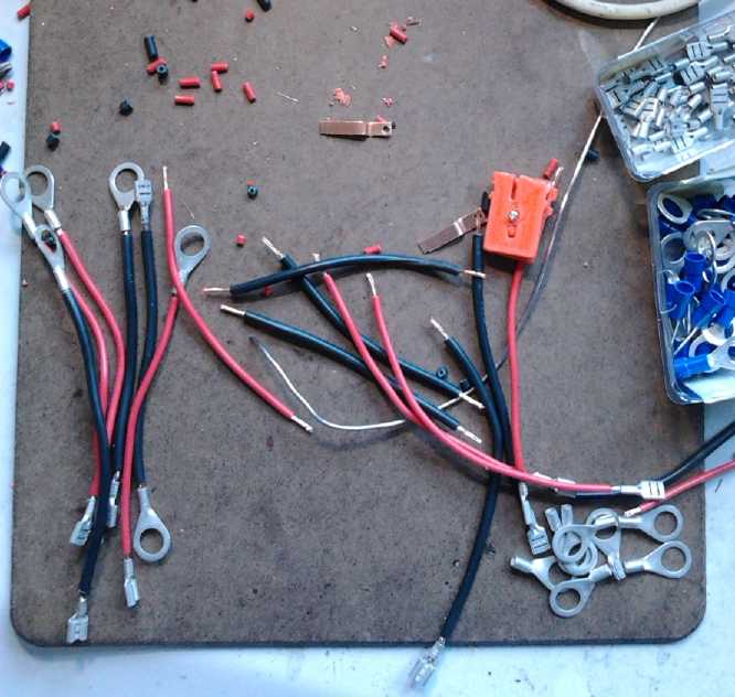
Wiring up about 15 click-lock sockets for Mazda RX7 batteries
 The "click-lock" sockets
will mate either with regular CAT
plugs or with "click-lock" or
"friction-lock" CAT plugs. They
fit in a regular CAT wall plate, but they stick out 9mm to make space
for the click mechanism and the plug surround. (Flush wall plates with
slots surrounding the sockets could be designed.)
The "click-lock" sockets
will mate either with regular CAT
plugs or with "click-lock" or
"friction-lock" CAT plugs. They
fit in a regular CAT wall plate, but they stick out 9mm to make space
for the click mechanism and the plug surround. (Flush wall plates with
slots surrounding the sockets could be designed.)
The click-lock and friction-lock plugs will only mate with
the click-lock sockets. The pins on the plugs have the same dimensions
and spacings as regular CAT plugs, but they're enclosed by an 8mm deep
surround, with a center rib of that same length separating the two
blades. The center rib fits into a slot in the click-lock socket.
These new CAT plugs and sockets address needs of battery
connections and any use where there's vibration:
1. Both the battery and the charger can be 'live'. Therefore the plug
blades are enclosed - "hooded" - as well as the socket receptacles. (I
recommend
putting the socket on the
battery and the plug on the charger.)
2. With vibration (as in a vehicle or any moving object), a regular
plug might eventually work
its way out and come unplugged. The friction-lock type requires a
definite tug to get the plug and socket apart. The click-lock type
requires that the click latches be held open to unplug it. The socket
is the same for both plug types.
To elaborate, the click-lock plug has a right angle or
steeper catch that
won't pull away from the socket's catch unless deliberately held open.
The friction-lock has a 45° angle
catch that will open if you simply pull hard enough. In practice, as
presently printed on my 3D printer, the click-lock plugs can be pulled
apart with a good pull without pressing the releases. But they won't
pull apart from vibration.
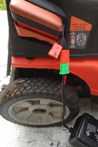
The first two sockets went into a 24 volt cordless electric lawnmower
so it could
be charged as two separate 12 volt batteries, for the same reasons as
the car.
At this point I didn't have the click-lock plugs yet, but the
'ordinary' plugs can
mate with the click-lock socket. (...Yuk, what gutless machines these
things
are!)
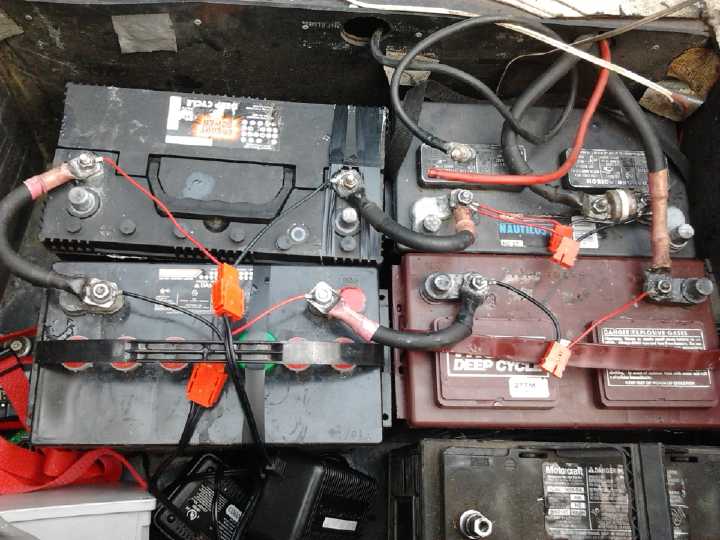
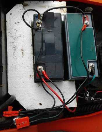
The rear battery compartment of the Mazda with CAT click-lock sockets
across each battery.
Two black 13.8V, 5A power supply/chargers with CAT click-lock plugs at
the lower left
are float-charging the left side batteries.
The heavy wired thing with the white ceramic center strip (upper right)
is a
450 amp fuse.
It would probably blow before the batteries melt down or explode in the
event of a short in the heavy wiring.
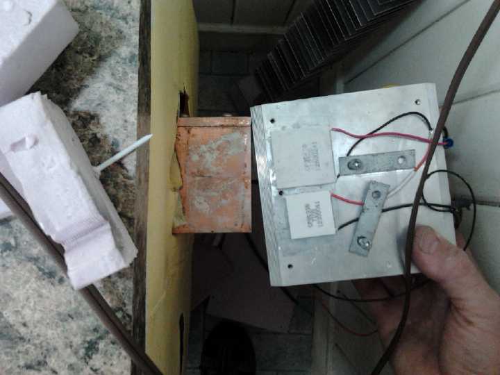
Fridge
The two 15 volt
peltier modules in
series didn't seem to make ice fast enough to avoid needing
considerable evening battery capacity - and none at all if the power
was
below about 12.5 volts.
On the 22nd I put 15 and 8 volt (both 8.5 amp) peltiers in
series to
cool the fridge, raising the daytime voltage on the 15 volt one from
6.7 to 8.54 volts. The voltage on the 8 volt unit was then about 4.81
from the total 13.35 volts. Both were still in the good efficiency area
of their charts. Typical
daytime current went up from 3.1 amps to 4.0. But the warm side
temperature rose from about 26 to 31. Partly it was the warming
weather, partly more heat generated from the higher current - in fact
the unit would be consuming 4.0A*13.35V=53.4W. Previously it would have
been 3.1A*13.4V=41.5W. With a single Peltier it had been around 85
watts with little additional cooling. The cold side was about -5 making
a 36 degree
spread instead of the 30 I had earlier, and with the higher spread the
increase in heat pumping didn't seem marked, although there was
definitely more ice after 12 hours or so. I raised the speed of the
fan. It lowered the warm side a couple of degrees. (I really want to
try out the evacuated tube radiator with ammonia-water. It has the
promise of quiet (no fan), best cooling, and lowest loss of cold when
the fridge is turned off.)
The cooling unit will be less voltage sensitive. Two 15
volt peltiers have nearly 7 volts each and over 3 amps during the day,
and cooling is decent. But with about 6 volts at night & well under
3 amps they can only barely attain a 45°C spread even with nothing
carrying away the coldness, so they can hardly keep a 30° spread
cooling a fridge. Whereas with one at 8 volts (at night) & 3.5 amps
it can hit 55° with no load, giving it more pumping ability at a 30
or 35°
spread.
The 8V, 8.5A peltier module at 4.8 volts would be
proportional and also have a 55° limit. It just has 8/15ths of the
same thermocouples in series as the 15 volt. They can be viewed
together as
being the same as a single 23 volt, 8.5 amp Peltier module.
But I noticed an unsettling detail in changing the
peltiers: I rubbed at the
heatsink compound on the copper bar while the peltiers were removed
with my
fingers, and felt a small lump or grain of some sort, which I
rubbed/brushed off. This may
have been preventing optimal surface contact of one peltier... which
just might explain why I thought it was working as well as the
single peltier at first, and then I changed my mind and decided it
seemed to make ice too slowly. Perhaps I'll try the two 15V peltiers
again sometime and see if the results are better than before.
Another factor appeared to be that the new cooling
arrangement with the new heat sink and fan and copper bar appeared to
bleed off cold (when the fridge was off) faster than the original one.
Whereas a tray with more ice than water would last 10 or 11 hours at
night, with the new cooling setup it only lasted 8 or 9. If a foam box
cover was placed over it at night, it would last around 11 or 12 hours.
This
shows how much coldness leaks out via the cooling mechanism. The
evacuated tube radiator, conducting heat at the bottom but not cold,
should presumably be much better, especially if its base block is
insulated. Unfortunately I didn't find time to try to make one in April.
12V versus 24V
Perhaps it's worth noting that the solar supply was
actually over
13.8V, not 13.35 volts, at the breaker panel. So at least .45V was
being lost in the wiring with the 4 amp draw. A 24V supply would use
1/2 the
current for the same device, so the voltage drop
would be .24, and so the losses would be a smaller percentage of the
total voltage - in fact, less than 1% versus 3.4%.
On the other hand, the fridge specifically would have
needed 3 or 4 peltier elements instead of 1 or 2 (rated 4A instead of
8.5A), which would each take heatsink space and leak cold from the
fridge when off. And LED lights are more easily run off 12 volts if a
standard is to be applied.
So I keep thinking of having both 12 and 24 volts. On the
other hand, for high power devices, 120 VAC from the street would
appear to be quite a good and very popular option to minimize wire
sizes and losses. An inverter by the batteries would take little heavy
wiring, and the 120 VAC wiring from it would be light.
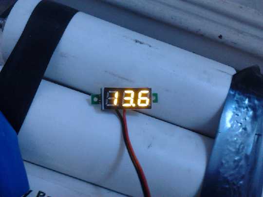
Mini LED
Voltage Display
Someone had some mini LED voltage displays for 12 volt
batteries, from China. I bought one (3$?) and put it on the solar panel
system batteries, and wondered why I'd bothered mounting the analog
panel meter.
 MSP430
Software Development Suite
MSP430
Software Development Suite
I figured a "Linux guru" friend would have figured out how
to get the
MSP430 Launchpad development board connected to a PC via Ubuntu Linux
for programming,
but he hadn't been able to get the computer to 'talk' to the Launchpad.
So I spent some time looking for info on the web.
Texas Instruments had an 'integrated development
environment' for programming them. I downloaded versions for Windoze
and Linux but somehow the theoretically simple functions of a
microcontroller software development kit took more computer than any
one I have to run it. There were text command line files at Ubuntu
Software
Centre... but how to get them working?
Finally I ran across this web page: dbindner.freeshell.org/msp430/
. The author uses essentially the software at the Ubuntu center, but he
describes setting up a couple of critical things in Ubuntu needed to
get the computer to recognize the Launchpad board/MSP430 as a USB
device, and
command line commands with the options needed to successfully compile a
program and send it to the board. Those are
the sort of initial setup things that most documentation and
tutorials take for granted you already know or have set up, but without
which you're dead in the
water.
After a second learning session on the morning of the 30th
I went at it that night and after a few hickups (like an MSP430 chip I
plugged in backwards) compiled and sent a couple of programs to the
board and ran them. Yay!
I have the idea in mind to write a 'front end' GUI program
in Python that composes the more common compile and debug command lines
for you - so you just click the buttons.
Electricity Storage - Turquoise Battery Project (etc.)
Unfortunately, I didn't get any chance to look at the MnMn Turquoise
Battery Project in April. Other battery types did get more than looked
at since I had an immediate need for batteries for the electric Mazda
RX7.
Lead-acid Battery Renewal with Sodium Sulfate: new technique
One of the batteries I renewed for the electric Mazda RX7
didn't stay charged. When the car was turned on, it would drop to 10 or
8 volts just from running the vacuum pump. I removed it.
Later, I discharged it with a halogen headlight bulb and
then shorted it with a wire, not only to 0.0 volts, but until all the
little noises of outgassing seemed to cease - about a whole day shorted.
Then I charged it up and got graph 1. [Oops, I didn't make
the graph!] It ran the headlight
(~3.5 amps) for a little over an hour at over 11 volts before dropping
to 10.5 volts. This was much better than quickly dropping to 10 or 8.
In the manner of battery renewal, I expected the next discharge to last
somewhat longer at a somewhat higher voltage. I charged it overnight.
It went on and off of charge in a cycle of less than a minute.
The next morning it was sitting at about 12.2 volts. I put
the headlight on with it... and it dropped to under 4 volts in a couple
of seconds! Perplexed, I left it sitting for a day or two. Then I tried
again, and this time from 11.8V it only dropped to about 8 volts
running the headlight. I left it another day. The voltage again sat at
11.8. When the headlight was connected it dropped to about 11.4 and
started an apparently normal discharge. I wasn't into running a long
test, so I left it a couple of hours. When I returned, it was 12.0v,
and running the light it started dropping slowly from 11.6. The
headlight was bright. In all this, it hadn't been charged since the
first time. I almost put it back into the Mazda.
Three hours later I tried again. Sitting voltage was 11.9,
and when it lit the headlight, the voltage almost immediately dropped
to about 4.5 volts! The next day, the the 26th, it was 11.8V and
started dropping from 11.4 with the headlight. After 40 minutes the
voltage dropped under 10.5. After 3 hours charging, it immediately
dropped to 8.4 volts when the headlight was connected. Was this really
the same battery each time, or was some gremlin swapping them around
while I wasn't looking?
NiMH 12 volt D
cell Battery Cases
Most people don't seem to think of NiMH batteries for much
of anything they want batteries for. They're excellent batteries, but
first, the economical wet cells have been kept off the market by the
corrupt, and the dry cells cost about as much as lithiums. The second
problem is how to make a bunch of individual dry cells into a reliable
large battery.
I would suggest one ideal use for NiMH dry cell
batteries: it appears to be a better drop-in replacement for a
lead-acid battery than lead-acid in regular gas cars, with the 13.8
(13.8 up to about 13.95) volt alternator being an optimum float charge
voltage for NiMH as well as lead-acid. In addition to lasting a decade
or two or maybe longer, it's maintenance free, much less damaged by
accidental discharge (ie, lights left on), and it drops the vehicle
weight by 15 or 20 pounds to continually save a little gas.
Mine has now been in the Tercel over two years, has run
down a few times, just once to too low to start the car (yes, always
from lights left on), and it still works like new. And this is in spite
of the fact that I often turn the engine off at long red lights and
then restart, and I have the idle set so low that the battery is also
discharging when idling at traffic lights, coasting, etc. -- practices
that killed my last 2 or 3 lead-acid batteries in a year or two. (The
gas saved paid for the batteries, but there's no sign I'll ever need
another battery now.)
Mine was made with plastic pipe "battery sticks", which
aren't a good fit in a space intended for a square lead-acid battery.
The new cases solve this problem.
The last time I tried making compact 12V NiMH cases, I had
3D printer troubles
and frustration. Perhaps luckily, I didn't get back to it for some
months.
Meanwhile I discovered that if the cases of the cells are touching
and they get hot, the plastic sleeves melt, the metal cases connect,
and as they're at different voltage levels, it's a short circuit and
everything goes up in smoke. That meant for safety and reliability the
case design should be modified to put some space between the cells.

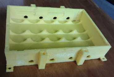
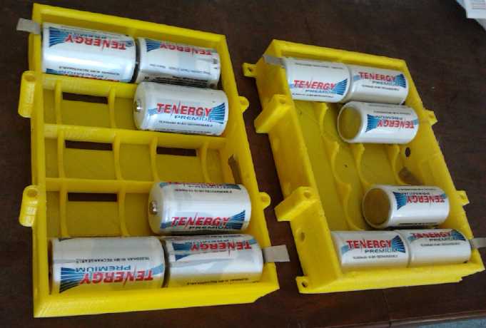
L: First new printed case.
R: Subsequent improved cases. The half-height inside ribs prevent
spreading of the walls with the pressure of the contacts.
On the 26th, thinking of
putting a NiMH battery or two
into the Mazda to illustrate the potential for battery mixing and
realizing the battery tubes could be awkward to fit
in, I finally tackled the NiMH battery case project with a fresh start.
I stretched the
design by 12mm, putting 3mm between each pair of cells so their cases
couldn't short together, which is a potentially dangerous situation.
The first 5 hour print
was a success, notwithstanding somewhat curled up corners - I had moved
the
main multi-battery case stacking supports away from the corners. It
seems corner warping is inevitable with a printer lacking an oven to
keep the plastic heated.
Then I cut the metal bits to connect all the cells. (after
which I discovered the D cells on the shelf very much needed a
recharge.)
I made a few improvements and printed more cases in the
next few days. I figured I shouldn't use less than 6 cases to replace a
lead-acid in Mazda, having seen currents over 100 amps even on slow
test drives. Theoretically they'll handle 50
amps intermittently and 30 amps continuous: 6*50=300 and
5*30=150 amps. But I wouldn't want them over about 20 amps most of the
time, and 6*20=120, and the currents while driving are usually under
that.
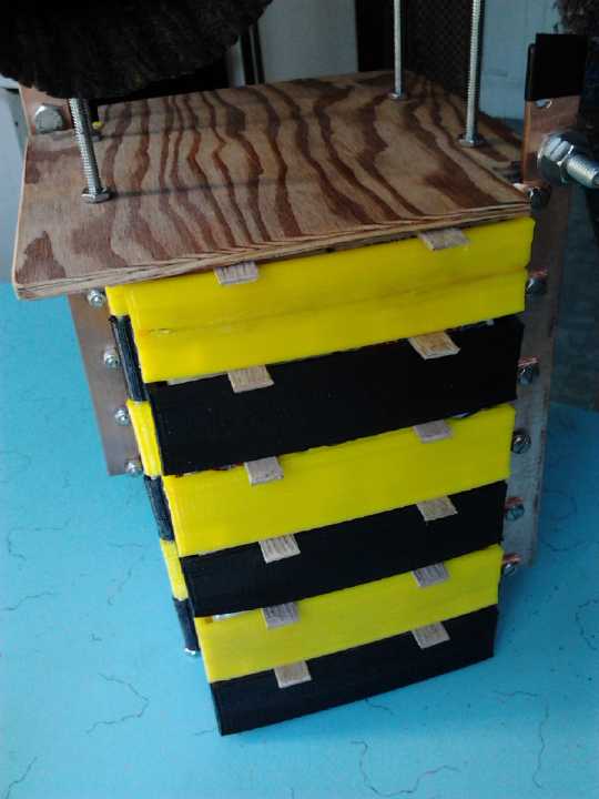
Battery with 6 stacked cases: 12V, 60AH, 180A, 300A intermittent.
Wooden spacers for extra ventilation.
(I'll tape some slit hose over those exposed copper bars.)
The plastic irrigation pipe made it possible to make
reliable big
NiMH batteries out of D cells (and they're still easiest); the new case
makes such a battery much
more compact, able to fit where a lead-acid battery fits with space to
spare, 3/5 of the weight, better performance, and much longer life.
...all at a much higher initial cost.
An attractive possibility in using small NiMH
batteries is that to increase capacity (as in vehicle driving range),
one can add new
batteries one 10AH bank at a time without removing old ones, until the
maximum space, weight or cost limit is reached. I left extra height on
the threaded rods to add a 7th case to the stack.
Tips for NiMH Battery Cases (preliminary)
(At the risk of providing far too much nit-picky detail and making
something simple seem complex...)
* Cases may be stacked to obtain a higher capacity battery with #10
threaded rod through the mounting holes. The top battery case needs a
cover to hold the cells in place.
* Long strips can be run through all the cases vertically for the plus
and minus terminals. If the currents are to be very high, connecting
each case to an external point or bus bar may be better.
* Spacers between stacked cases will improve ventilation. Place strips,
eg, of wood, so they hold the cells in place.
* These cases are intended for use within a protected space, not out in
the open. Likewise, it isn't intended that the cells be inserted and
removed on any regular basis, especially since the cells hold the
connector tabs in place.
* Be sure all cells are well connected. If they move back and forth
loosely when pushed, bend a metal connection tab 'V' out a bit more
with pliers. If they pop out when installed or are hard to put in, bend
the 'V's shallower.
* Be sure all cells are correct polarity when installing - measure the
voltage after inserting cells.
* Be sure the battery is the right way around - double check everything
before
connecting. (Remember, 3 of these batteries ganged together will start
a car! ...or maybe a fire.)
* 3D printer people: Don't eliminate the space between the cells. If
the
cells get hot, the sleeves will melt, the cases will touch, and
everything will go up in smoke, perhaps starting a fire. (In fact,
pieces of something heat resistant between cells and between cases
isn't a bad idea. Mylar or acetate, motor slot paper, wooden tongue
depressors...)
* Badly overcharged NiMH dry cells survive best if they are upright.
Level isn't bad. Upside down, they tend to lose too much electrolyte if
they build up enough heat and pressure to vent. They can't all be
upright, but they can be placed to minimize damage or the number of
cells damaged if it seems like a useful thing to do. A reliable charge
system is better.
* We know the the case bottom corners and edges are warped. The cases
are considered 'good enough' to use. (If it was a 20000$ printer
instead of an 800$ one, results might be improved - for a higher price.)
NiMH "Super Battery Stick" not so
super
I made the "Super Battery Stick", a single 4" PVC plumbing
pipe which turned out to be a good size to hold 7 banks NiMH cells, a
year or more ago. It seemed like a great idea at the time. With no EV
running, I had been using it in the 12
volt solar PV system. I had put a spring clip on one end for each row
of
cells
to press the cells in each row together for good connection. But some
springs might be a little looser than
others, and there was no way to test the connection of individual rows.
So ever since making it, I've been worried that all 7 rows of 10
cells might not be making good connection. With all the new battery
cases I was
making, I
decided to take it apart and use the batteries in the new cases.
Sure enough, 30 of the 70 cells weren't well charged, 15
being about 1.2 to 1.25 volts, and 15 down around 1 volt, the minimum
that NiMH's should be allowed
to drop to to avoid corrosion of the negative (metal alloy with fast
corroding lanthanum) electrode. (I don't know why it wasn't an even 10
or 20 cells at each level.) I won't use the "multi-rows in a tube" idea
again.
I am however still considering that I'll probably use the
older single 12V battery stick designs in situations where there's
sufficient
space and no need to have the "square" format of the printed battery
cases, which take 4-1/2 hours to print, extra labor to assemble, and 6$
of plastic filament and copper plate.
http://www.TurquoiseEnergy.com
Victoria BC