Turquoise
Energy Ltd. News #65
Victoria BC
by Craig Carmichael - July 5th, 2013
www.TurquoiseEnergy.com
= www.ElectricCaik.com
= www.ElectricHubcap.com
= www.ElectricWeel.com
Month In Brief
(Project Summaries)
- Next Projects possibilities, Building the Green Economy
event, Electric
Mazda, Solar 'DC grid tie', 3D printer repair (sigh!), 'Ultra-efficient
Transmission' work, new chemie batteries - MnMn still looks best
In Passing (Miscellaneous
topics, editorial comments & opinionated rants)
- extended supply chain breakdown
Electric Transport - Electric
Hubcap Motor
Systems
* PGTC Transmission: Clutch mechanism figured out and built. Now motor
controller has quit - sigh!
* Idea: A simple 2-speed transmission with one clutch pedal shifting? -
pedal down is low; pedal up is high; pedal centered is neutral.
* Electric Weel motor design change: 24 coils as 2 sets of 12, 2 motor
controllers @ 48V, 150+amps.
* Homemade "Segways"! from Germany - with schematics, source
code, ...
* Mazda RX7 stuff - maximum range 13Km, individual battery float
charging system, NiMH
batteries are charging more slowly than lead-acids - and not to very
full
Other "Green" Electric Equipment Projects
* Solar PV main distribution panel things & lead-acid batteries
Electricity Generating (no reports)
Electricity Storage - Turquoise
Battery Project etc.
* Production Prototype Cell #4 (PP#4): MnNi - a nickel negode to try to
isolate MnMn electrode/cell problems
* Worked crappy - rebuilt.
* Low pH (6) causes high self discharge! (Well, duh!)
* PP#5: Ni-Ni. Even with "traditional" Ni(OH)2 posode and pH (near?)
14,
same self-discharge problem and even lower conductivity.
* Carbon fiber cloth separator sheets to improve electrode conductivity
* Mn-Mn is better. I'm returning to it - with carbon fiber cloth, paper
and nylon separator sheets, and any other new tricks I can think of.
With a 5-fold improvement (over PP#3) it would be a practical battery,
whereas the NiNi would need a 20-fold improvement over PP#5 - and even
then it would be just 1/2 the voltage.
* Perforating metal for 'porous' electrode conductors: a silkscreen
with tiny holes and acid? ...and faster PCB etching?
No Project Reports on: DSSC
solar cells, LED Lighting, Pulsejet steel
plate cutter, Magnetic
Motion Machine,
CNC Gardening/Farming Machine (sigh, maybe summer 2014?),
Woodstove/Thermal Electricity Generator, Peltier & vacuum pipe heat
pumping.
Newsletters
Index/Highlights: http://www.TurquoiseEnergy.com/news/index.html
Construction Manuals and information:
-
Electric Hubcap Motor - Turquoise Motor
Controller - 36 Volt Electric
Fan-Heater (say, this heater is now obsolete! Use Peltier module heat
pump!)
- Nanocrystalline glaze to enhance Solar
Cell performance - Ersatz 'powder coating' home process for
protecting/painting metal
Products Catalog:
- Electric Hubcap Motor Kit - also please inquire about Electric
Caik
3KW Motor Kit
- Sodium Sulfate - Lead-Acid battery longevity/renewal
- NiMH Handy Battery Sticks, 12v battery trays & Dry
Cells (cheapest NiMH
prices in Victoria BC)
- LED Light Fixtures
Will accept BITCOIN digital currency
...all at: http://www.TurquoiseEnergy.com/
(orders: e-mail craig@saers.com)
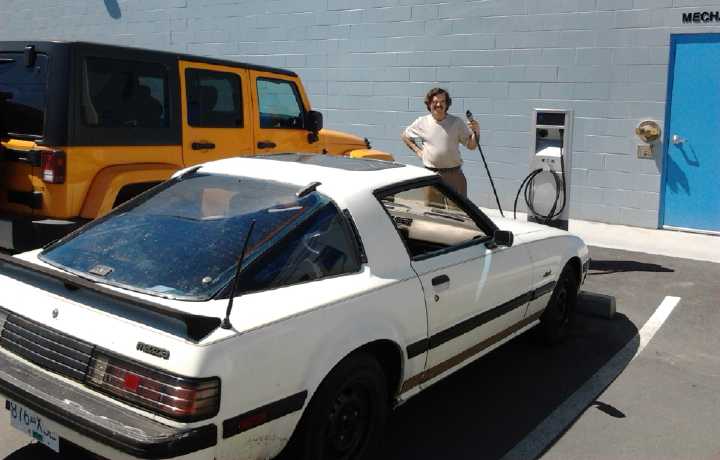
June in Brief
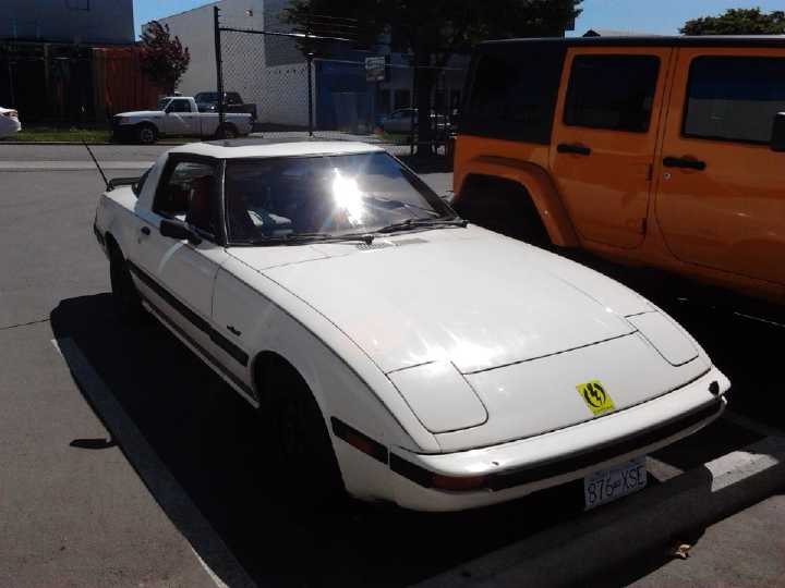
Mazda RX7 parked at Westburne Electric, early June
They had another one of those fancy EV charging stations that I
can't use
Tom did a video here of me driving it:
www.youtube.com/v/vSX3JQWIKng
The electric Mazda RX7
continued to occupy time into mid month. Now I'm
driving it and with most of its
components now functional, where should I next turn my attention? The
possibilities
were and are endless:
* Fix the 3D Printer (sigh!)
* the Referendum Web Site to be developed
* some exciting new ideas as well as unexplored old ones for new
chemistry battery making
* the Chev Sprint ultra efficient electric transmission/planetary gear
torque converter... that sat idle all winter after exciting progress in
September
* then, a variant of that transmission to finally make the Electric
Hubcap
car hybridizing system
* motors and motor controllers to be made including:
- the 13.5KW high torque Electric Weel motor that must be
about 3 years old and hasn't been finished
- the wheel rim/arc motor for bikes
- more Electric Hubcap and Electric Caik motors, to have
kits on hand to sell or to use
- more BLDC motor controllers. It also makes me nervous
that only the V1 controller and not the V2 is running reliably.
- Optimize
component values to make the V2 more reliable and robust.
- other motor controllers such as VFD for AC motors, and
controllers for DC motors with brushes. These can be variants of the
existing
controllers, but some high power ones, like 300 or 400 amps at 36 or
48 volts, would be good to have for cars, even with very high
efficiency.
* The "Outboard from Scratch" - and casting the more efficient-looking
prop (plastic prop from a scuba unit).
* lots more 12 volt DC house wiring, LED globe lighting and other solar
equipment projects that could be done. I should make a production
version of the circuit board for the LED globe lights: with CAT plug
pins - the little round power adapter plugs are frustratingly
unreliable, especially
if you have to wire one yourself, and of course you can freely plug in
the
wrong voltage or polarity of adapter.
* the peltier/thermoelectric heat pumping and thermoelectric
electricity generator projects (All these projects use almost exactly
the same
components.)
* now having reliable means to do simple circuit boards and now also
microcontroller programming, there's various microcontroller-electronic
projects:
- the fridge control
- peltier heat pump control
- solar PV system 'dump load' and other ancilliary
equipment control
- motor controller 'overcontrollers' with RPM limiting
- the individual battery monitor for EVs of all types
...and in case those weren't enough possibilities, then moving just a
little farther afield I could try getting back to other projects I
haven't had time for in quite some time or haven't got very much
started on:
* high refraction, low reflection 'pebble glaze' (nanocrystalline
titanium dioxide borosilicate glaze) solar panel cover glass and DSSC
solar panels
* pulsejet steel plate cutter
* magnetic motion machine
* the ocean wave powered electrical generator of the recently described
type
* CNC gardening/farming machine
On the 4th I decided that with the onset of good summer
weather, I should 'make hay while the sun shines' and do the things
with outdoor activity. That means physical EV things, and
especially the PGTC transmission/Sprint. That car has now sat over two
winters in one place, and I fear things may start seizing up like on
the Mazda.
Also, I decided to work on the long 'overdue' Electric
Weel, which a couple of people are interested in, and try and make
molds to cast the stator body parts. Of course, people have expressed
interest
in my other motors too and yet no one has bought any kit yet. I got as
far as a 'life size' drawing of an octagonal section.
And I also decided to try a few battery chemistry things,
because surely it's pretty close, and the short range Mazda shows the
glaring need for better yet economical batteries. Other things could be
worked on
on occasional evenings or put off until inclement
weather. Even if one achieved only the 50 watt-hours per kilogram of
nickel-iron flooded cells - with of course high current capacity and
long cycle life - they'd be better than lead acid. With modern
techniques and materials one could certainly make much more
economical and better performing NiFe batteries than Edison did 100
years ago. But MnMn seems to be the superior choice.
Electric Mazda
The first thing I actually did, on the 4th, was to put in
a plywood and carpet cover over the battery well in the rear of the
Madza RX7, with a few more bits of matching carpet surround. It looks
nice, provides a cargo space, and muffles the noise coming through the
battery well from the rear axle and wheels.
The next day was the VEVA electric car club, and I finally
got to show off something besides semi-functional battery prototypes,
and once the electric outboard motor, even if the car wasn't using
motors and components I'd made myself. But there was a free, outdoor
Buffy
St. Marie concert that evening. Everyone rushed off to that and paid
little attention to the car, except I gave someone a ride.
After it was over we went to his place and he showed me
his 'new' Morris Minor, a 1960's British car produced with a 948cc
engine, that he wanted to make electric. (See Morris Minor)
On the 14th, I swapped out the weakest lead-acid battery
in the RX7 for a new one Tom Sawyer loaned me. With that and upping the
NiMH charger voltages a bit, the car's range went up to about 8 miles
(13Km)
or better, with the somewhat undercharged NiMHs becoming the limiting
factor. It's a long way
from the 70Km or so the original owner got with 18 new 8-volt high
current golf cart
batteries.
Later Tom came over and insisted on helping me wash
the RX7 (which he doubtless realized I would never have gotten around
to myself) in preparation. The car works better through my efforts;
that it
looks rather good must largely be credited to Tom's enthusiastic
'detailing' efforts.
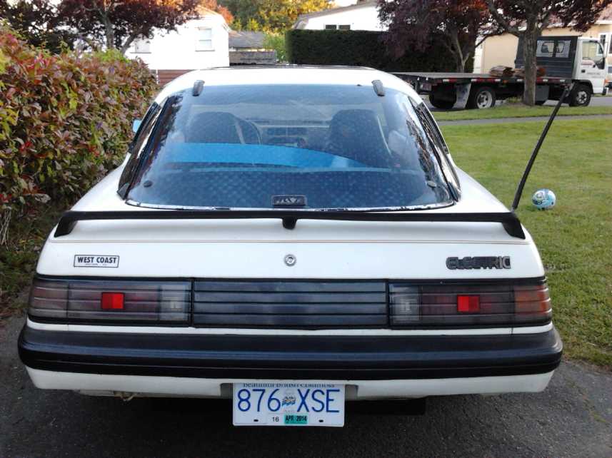
Finally, after some great black 'rubber' texture paint (bumper, rusty
battery well steel under),
we had seen "Electric" nameplates on a converted car at the April VEVA
meeting.
Tom ordered a couple from Canadian Electric Vehicles and we put one on
the back.
Not only many conversions but the manufactured electric cars seem to
want to hide the fact that they're electric, giving the general
public the impression as they travel that there are essentially no
electric cars on the road even when there's one here, one there...
I think I want to paint the black parts between letters white, because
it doesn't show up very well.
Two of the NiMH batteries were below 12 volts, eg 11.8.
They surely had little life left. The other two were just over 12v, eg
12.10. The lead-acids were all above 12.2 volts. If I beefed up the
charging of the NiMHs to get them up to 14.0 volts it should surely be
good for 10 miles/16Km. Then again running lead-acids down too far
with no sodium sulfate in them is worse than running down NiMHs.
The best battery
appeared to be the
"reconditioned" one I had purchased at Battery Doctor. It was still at
12.6 volts and so apparently could well have driven at least as far
again,
total 16 miles/26Km or more.
Of course, while the ever decreasing voltages can be seen
by glancing at the CycleAnalyst while driving, there's no indication of
which batteries are dropping by how much when you hit the pedal. Is it
mostly the NiMHs are at
the end of their charge and going way down?, or are they doing okay
while the
weaker lead-acids are going down to 8 or 9 volts?, or are they all
dropping more or less equally? These are the sort of questions my
individual battery monitor is intended to answer.
Solar House Equipment
Also that day I repaired a 20 amp,
13.8 volt power supply I'd been given some months ago. (blown
transistor from foolishly placed, clamped, output wires that melted and
shorted together.) It's exactly what
I've been wanting for the
solar PV system as the backup "DC grid tie" power supply. I fit it in,
replacing a 12 amp
battery charger I'd been using. It gets pretty hot doing 100-200 watts
if the car is plugged in and it's cloudy. It has its own 20 amp breaker
in the main panel.
Building the Green Economy
Event
Showing EV mixed battery system to Murray Rankin, MP.
 On Saturday the 15th, I had a display table at Building
the
Green
Economy, an event put on by Murray Rankin, member of
parliament for Victoria BC. Before the event started, I presented him
with a printed copy of my booklet Fundamental Principles of
Democratic Government - Towards Utopian Systems of Governance,
which he seemed interested in. He said he would read it, and asked me
to e-mail him to discuss it later. There was an hour long panel talk
with short talks by several people. Guy Dauncey, who started the BC
Sustainable Energy Association, spoke last and gave
a surprising, brilliant talk mainly about about one of the broadest
issues that nobody talks about except on youtube:
"locally has to be in a global
context", the impoverishment of people and nations by the bloated
financial sector's intrigue
and fraud, the need for more local, accountable public financial
institutions and for local or regional currencies, and the need for
everyone to
learn more about how finances work - and how they ought to work. I just
hope many of the audience of perhaps 130 understood the background of
systemic, unsustainable global financial problems which he was
addressing. Sustainability has to begin with sustainable societal
institutions, and we ain't got 'em.
On Saturday the 15th, I had a display table at Building
the
Green
Economy, an event put on by Murray Rankin, member of
parliament for Victoria BC. Before the event started, I presented him
with a printed copy of my booklet Fundamental Principles of
Democratic Government - Towards Utopian Systems of Governance,
which he seemed interested in. He said he would read it, and asked me
to e-mail him to discuss it later. There was an hour long panel talk
with short talks by several people. Guy Dauncey, who started the BC
Sustainable Energy Association, spoke last and gave
a surprising, brilliant talk mainly about about one of the broadest
issues that nobody talks about except on youtube:
"locally has to be in a global
context", the impoverishment of people and nations by the bloated
financial sector's intrigue
and fraud, the need for more local, accountable public financial
institutions and for local or regional currencies, and the need for
everyone to
learn more about how finances work - and how they ought to work. I just
hope many of the audience of perhaps 130 understood the background of
systemic, unsustainable global financial problems which he was
addressing. Sustainability has to begin with sustainable societal
institutions, and we ain't got 'em.
I put the electric Mazda RX7 on display with the hood up
out in the parking lot, with a sign on my table saying it was there. I
showed it and explained what I was doing
with mixing non-identical batteries and separate charging to a number
of people. Jim
Harrington brought some economical LED house light bulbs to add to my
small 12V collection, but as usual no one bought any, even once the
amazing electrical savings were explained. Perhaps everyone's been made
skeptical by the claims of compact fluorescent bulbs, which were
heralded as
being better than they proved to be in most peoples' experience.
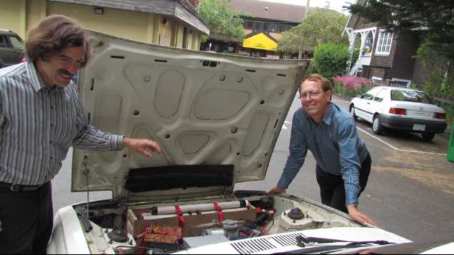
At the end of the event, Rankin's assistant Edward, who
had invited me to the event after we chanced to meet earlier in the
week, asked if he could get some pictures of me and Rankin out by my
electric RX7. So when we (Rankin too!) had stacked up the chairs
and tables, and I had packed up the Electric Caik Outboard and my boxes
of
stuff, we did the pictures and they watched me drive off burning no
fossil fuel.
Magnetic Control with Light?
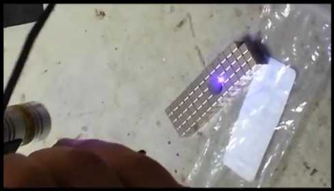 Jim Harrington
and his Ecosat Satellite team have taken
lasers - one violet or UV and the other IR, both in the
x100's of milliwatts range - and shone them on a round disk of
pyrolytic
graphite floating by magnetic repulsion just above a "checkerboard" of
cubic supermagnets. If
the laser is shone near one edge of the graphite, it jumps in that
direction, right over the magnetic boundaries between magnet cubes to
the next corner boundary. Shine at the other side, it jumps back.
There's recent research on the reciprocal relationship between light
and
magnetism, but I don't think it's ever been graphically seen and
demonstrated before. Jim says it could revolutionize space flight.
Jim Harrington
and his Ecosat Satellite team have taken
lasers - one violet or UV and the other IR, both in the
x100's of milliwatts range - and shone them on a round disk of
pyrolytic
graphite floating by magnetic repulsion just above a "checkerboard" of
cubic supermagnets. If
the laser is shone near one edge of the graphite, it jumps in that
direction, right over the magnetic boundaries between magnet cubes to
the next corner boundary. Shine at the other side, it jumps back.
There's recent research on the reciprocal relationship between light
and
magnetism, but I don't think it's ever been graphically seen and
demonstrated before. Jim says it could revolutionize space flight.
I
can see a potential use for it in magnet machines to generate
electricity, where the effect might help generate larger circular
magnetic
imbalances to get more power from a smaller magnet machine. And I'm
probably not even scratching the surface of the possibilities.
3D Printer Repair
My RepRapPro Mendel 3D printer hadn't worked since I
started programming the TI MSP430 using the Launchpad board. I've had
ongoing
converse with their tech support. Out best guess (theirs and mine) is
that somehow programming the MSP430 was also programming the
AT-mega1284 chip on the printer's Melzi board, and it had wiped out the
firmware and the bootloader for uploading new firmware, via the USB
port. We figured I'd need a
USB "AVR" "ISP" programmer to reprogram the boot loader so the Melzi's
AT-Mega firmware could be reprogammed. The Arduino Uno board I got as a
possible alternative to the MSP430 Launchpad appeared to have the right
header pin plug on it, labeled "ICSP".
I spent most of the 23rd on the problem. The Uno's port
proved to be an input programming port rather than an output. However,
only one wire was different. I cut the trace and converted it, and made
a short cable to go to the Printer's identical port.
The software was another problem. Following the
instructions on the reprappro & reprap web site, I got "Burn
Bootloader" to work. (Apparently.) That was a big step. However, the
LED on the
printer board still didn't light, and I couldn't upload the firmware. I
must be very close, but something isn't quite right.
Once it's working again, I have the 3D '.STL' design for a
J1772 car charging plug. I intend to try using the 'ground' wire in the
sockets as a 'neutral' to use with 120 volt charging systems - or at
the very least with my charging system where I can roughly balance the
load by putting 1/2 the chargers on each side of the 240V line.
Ultra Efficient Transmission/Chevy Sprint - motor controller blowout
(sigh!)
Then I went out and made the clutch linkage for the Sprint
'ultra efficient planetary gear torque converter' transmission, having
done a spring loaded belt tensioner the previous day. After assembling
the mechanism properly on the 25th, it seemed ready to attach the motor
controller and batteries, and test.
But now I'd used the previous battery in the Mazda and
would have to find a new arrangement for that. I could use 100 more
NiMH D cells, but am uncomfortably far in debt. I decided to settle for
50 D cells, and to pull the seven-3D-printed-trays battery from the
Mazda, and simply have one less battery in it for now. By
changing the bus bars in the tray, I made it 24 volts, 30 amp-hours.
I added 3 'quintos' pipe batteries taken from the solar PV system for
the third battery. That could certainly run the Sprint
around the yard if it could be coaxed into moving at all.
On the 28th I made a new wooden box to hold the batteries
in the Sprint
radiator area, the original one for long pipe batteries having proven a
little too wide to get in and out with the motor/transmission in place,
and the second one having lost its short pipes battery into the Mazda.
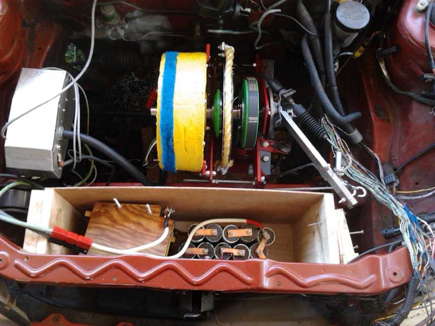
Under Sprint Hood
Front: 36v battery in open box,
Left: motor controller
Center: yellow motor, PGTC with slip pulley, flat belt on green pulleys,
To the right: friction cable & pulleys that tension yellow rope
(from automatic gear shift lever)
Right, under: clutch linkage to slip flat belt (from clutch pedal)
New Chemie Batteries
I tried out a couple of other combos of battery
chemistries to see if I could isolate the causes of self-discharge and
poor conductivity in my NiMn-Mn in KCl ("MnMn" for short) cells to one
electrode or the other. Earlier, an Fe electrode had undergone capacity
decay with each cycle in slightly less than pH 14 solution and I gave
up on that. MnNi (PP#4) didn't seem to work any better than MnMn
including having high self discharge, so the suspect was the Mn posode.
(Ni negodes don't work in pH 14 BTW - but 10-13 seems okay.) Then I
tried NiNi
in another cell with the same negode (PP#5), and that didn't work any
better either despite its low voltage.
Since PP#3 (MnMn) had been
gradually improving with each cycle both in capacity and with gradually
dropping self-discharge, further improving the construction and using
MnMn chemistry seems like the best bet. If it had had about 10 times
more
capacity and if the self discharge had continued to drop (and also if
it
hadn't suddenly quit holding any charge, with electrode powder leakage
evident) it could have been a practical cell - and over 2 volts. It
might have even got there simply with enough cycling. While the NiNi
also seemed to improve with cycling, it would seemingly need a
substantially larger improvement, and even if that was obtained it's
just over 1 volt and
twice as many cells would be needed.
Two things I meant to do in June and didn't were to finish
the CAT standard 12 VDC plug & socket promo video, and to evacuate
a pipe with
ammonia as the fluid, to get lowered boiling and freezing points. You'd
think I could have got to those rather short projects! But projects
once started seem to have a habit of growing.
In Passing
Incidental news, editorial comments & opinionated rants
Warnings from the spirit
beings that oversee this planet have been coming over the ether then
through e-mail lists (1111progress, TML, CCC, CWM...) for at least a
couple
of years now that we're headed for a very rough time. This month it was
stated that when the main crisis hits, the disruption to global supply
chains is likely to last about 3 years, and almost nobody has put away
enough
food to tide them over for so long. Plus, many people have left
important things out of their supplies, like salt or whatever.
It seems reminiscent of what I've heard
of the Irish potato famine. When potatos came to Europe from the new
world, they grew great, and they supported a large population
increase in Ireland. Then the potato crops got a blight. It spread
across the
island and people went hungry. Nobody actually starved in the first
year. But by the second and third potatoless year, everybody had run
through everything they had and mass starvation ensued. There was a
great exodus of Irish people desperate to go anywhere on any outbound
ship. Many went to America. 2 million people, perhaps 25% of the
population, died or fled. As with today's crisis, there were a host
of political, ethnic, religious, social and economic factors
exacerbating the problem.
Accompanying the financial fraud that's impoverishing the world today,
we also see
increasing levels of natural(?) disasters occurring around the globe.
And there are all those new, antibiotic resistant diseases as well as
old diseases which will likely strike as diseases usually do - when
populations are in hunger and want. It sounded like perhaps five
billion people are
likely to ascend prematurely to the mansion worlds in the coming years
or perhaps in the next decade or two, reducing the global population to
two billion. It's surprising how global it all is, with even China
suddenly and unexpectedly facing a "credit crunch" similar to that of
so many other lands.
Although the crisis is essentially man-made, with the
worst aspects being
generated by the machinations of those in economic and political power,
something fairly
drastic has evidently become necessary in any event owing to an
overpopulation of unthinking, uncaring and unspiritual materialistic
people who are destroying the planet. The horrific crisis and its
outworkings
will however lead to tremendous quickening of individual thought and
consciousness, and rapid planetary progress. The world will be a
different
place, just as pre- and post-famine Ireland were different places in
just a few years.
Things that will still have currency value after people
lose confidence in fiat currency (which always collapses in a few
decades if you look
back into history) include silver and gold (which are now being bought
up at record rates), and I expect bitcoin and other digital currencies.
With internet transactions, digital currencies may be the only form of
money that can be sent to another place quickly and without risk of
theft in transit. Bitcoin is 'fiat', but it can't be inflated away to
nothing: no more than 22 million bitcoins can ever be created because
the program was written that way. If it catches on, people will be
using milli- micro- and perhaps even nano-bitcoins for transactions.
And even by itself it may be the beginning of the end for the financial
system as we know it since most transactions will require no
"middleman".
We can see a crescendo of calamity
rising around the world, but we don't know exactly how the collapse
will
unfold or
the timing (everyone asks the economists on youtube "how?" and "when?",
and the usual and honest answer is "I don't know."). One of the
motivations for getting the electric Mazda is that it just might
give me a way to get around in case extreme fuel prices or shortages
develop before I've got my own
'ultra-efficient' vehicle drive on the street.
As to those "natural" disasters, there's substantial
evidence some of them are being generated by HAARP projects. When HAARP
antennae aim millions of watts of radio wave power at an area of
Earth's ionosphere, the ions heat up. They rise and are dispersed,
being replaced by non-ionic air that wells up from the stratosphere.
This causes low and high pressure zones directly and severely affecting
weather, and also brings unfiltered sunlight with all its UV radiation
down to ground level, which is a possible reason for otherwise
unexplained big die-offs of plants and animals. Weather control was one
of the ideas behind the system, as claimed in its 1990s patent. It's
even being said HAARP
effects can trigger earthquakes. I don't really follow that part.
Fracking can almost doubtless create earthquakes. Then there's "seeded"
jet "chemtrails" supposedly with stuff in them. I don't follow the
rationale for
those either and suspect the whole story is just vapor, but one
theory says the alleged chemicals react with the HAARP radio waves to
magnify the effect.
Some are asserting that
HAARP and or its sister antenna arrays are responsible for generating
global warming (makes more sense than CO2, a so-far fairly small
increase to a trace gas), for hurricane Katrina increasing in
size and being
steered directly onto New Orleans, Hurricane Sandy hitting New York,
the
Indian Ocean earthquake and tsunami, the Japan earthquake and tsunami
and earlier recent earthquakes in Japan and China, dead dolphins with
burned flesh washing up on beaches in the Persian Gulf after a bizarre
"fire tornado" over the water, and the extreme US drought of summer
2012. Much of this stretches credulity. But then, so would some of
these
extreme weather and geologic events if we didn't have clear proof that
they did happen.
The celestials say the people running HAARP and fracking
programs have
no idea what effects they're causing and that the repercussions of
these disturbances will take thousands of years to completely settle
back to equilibrium.
Aside from personal and family physical preparations to
tide us over an extended supply failure, what
can we do? Some may at some time find themselves in some position to
make a big
difference by a courageous personal act, like Julian Assange, Bradley
Manning, Ed Snowden... or millions of unsung people doing what they
think is right in spite of implicit or explicit negative consequences
to their
career or person. For the rest of us, the answer is to improve ourself.
This
seems too paltry, too insignificant, too mundane, to be the means for
changing a world: but the whole world is
made up of people like us, and only better people make a better
world. Education is vital - learn what's going on, how things work in
our screwy society, and think of better systems. We need to invent new
and sustainable systemic tools and institutions to prevent people from
relieving the citizenry of power by usurping it themselves and ruling
instead of leading. Clear separation of executive and legislative
powers and the choice ranking vote will help politically, and the
citizenry also needs to control its monetary systems.
And there's one thing the
celestials repeat time and again - "hit us over the head" with, as it
were: take 10 minutes a day out of your
busy schedule and meditate, or take a quiet, meditative walk. Still
your mind to make it receptive to the leadings of your
own guiding spirit. These mentally quiet times are when you grow in
spirit and advance in psychic status. Even if nothing seems apparent,
it's happening.
And while making whatever preparations you feel are
prudent and applicable, hopefully without unwarranted disruption to
your life, fear not! The universes are evolving towards
perfection according to the Universal Father's grand plan. The 'local'
Lucifer
rebellion is over (ca. 1986), and our world along with several others
is now, somewhat swiftly
and
painfully, being yanked back into the regular circuits before we
destroy ourselves with the leftover products of his ways of thinking,
which has greatly delayed our evolution towards the eventual 'era of
light and life'.
Electric
Hubcap Motor Systems - Electric Transport
Chevy Sprint: Ultra-efficient variable "PGTC" Transmission... and
the next blown motor controller
The biggest draw to 'ultra-efficiency' is the substantial
range improvement to be had with any given set of batteries. Another
is with the Mazda burning 160 to almost 200 watt-hours per kilometer,
or 1.6 to 2¢ [at 10¢/KWH], _assuming_ high charging
efficiency (which I don't really think I've got), lower energy use
would reduce the fuel cost, or the load on the solar collectors,
notwithstanding that it's already so much cheaper than say 14¢/Km
for gasoline.
A while
back, I came up with the idea that moving the
whole motor and pulley shaft up and down might be easier, and would
probably be better, than having an idler wheel to tension the belt.
Now I considered that given the tiny amount of travel
needed to tighten or slip the belt, perhaps the motor could be fixed in
place
after all, and only the other side, where the belt pulley was close to
the end of the shaft, needed to pivot. That seemed much more doable.
The slight twist of the pulley and shaft could be accepted.
I also considered that if my plastic flat belt pulleys
didn't hold up under the pressure or couldn't be tightened enough to
prevent slipping when tight, I would swap them for metal V-belt
pulleys and link belt.
With these ideas I got back to the long-stalled project.
On the evening
of the 17th I put the shaft and pulley set back together with some
adjustments, and figured out where and how to mount the spring to hold
the belt tensioned, and how to position and apply the clutch cable from
the pedal to compress that spring and slip the belt. On the 22nd I made
the spring part and on the 23rd the clutch linkage.
Not until the 30th did I put in the new battery box with a
36v, 30AH NiMH battery in it, and try it out. As soon as I tried
reverse, the motor controller blew. A video from a camera showed that
the belt had slipped off the pulley before that, so it not only blew,
it did so with no load.
This was quite unsettling, as this was the one controller
with an impeccable record. It had run the Electric Caik outboard in
February just fine. Did I have decent controllers, or were there still
circuit problems? But as I disassembled it, I discovered a loose wire
clamping screw, which held the output wires for phase "B", which was
where the blown mosfets were. With any loose connection in the high
power circuits, no further explanation of the failure is necessary...
except for why it might have been loose and how it might be prevented
in the future. The area was a bit cluttered with wires, and messes abet
accidents - could it be made cleaner? A better question might be
whether I should put in the TVS (transient voltage spike) back-to back
protection diodes that I bought for the purpose quite a while ago.
Further, when I took it apart and did the repair, I found
two sense wires attached only at one end. They should have been removed
long ago but went unnoticed in the wiring 'clutter'. If either bare end
had touched the case or some other wrong place that too would probably
have explained the failure. I don't think I'll look for some unknown
design problem at this point.
The drive belt will need a guide to keep it from going
sideways. Another thing I found was that the clutch guide slot bolt had
tightened itself up as the clutch went in and out a few times, so the
mechanism no longer moved freely. I had already thought of tightening a
nylock nut on the end to prevent it from turning. Evidently it's a
necessity even for a little testing.
A Simple 2-Speed Transmission? - Morris Minor
In thinking about the
Sprint
transmission, there are so
many ways a transmission could be made that my mind goes off on
tangents at times. This process was abetted by seeing a Morris Minor
that was to be made electric, and hearing that another one had been
done simply by putting an electric motor straight onto the drive shaft,
and putting in a higher gear ratio rear differential. This got around
many inefficiencies of a regular automotive transmission. But the motor
was probably bigger than would have normally been necessary, and
evidently it was sluggish getting rolling - not a surprise. It probably
also ran at a rather high RPM on the highway.
So I started thinking the Minor should work a lot better
and need a smaller motor with
even a two speed transmission. And, that any belt transmission would be
far
more efficient
than a geared transmission oozing oil around. Also, a belt transmission
with reducing pulleys
would eliminate the need to change the differential.
Then there's that
clutch pedal idea. On pressing a clutch pedal, a belt-clutch system
could
loosen belt tension... or tighten it. ...Or, it could loosen one
belt and tighten another. When the clutch pedal was pressed 1/2 way
down, both belts could be loose - neutral. When it was fully pressed,
the pressure of the foot could tension a belt (or pair of belts)
providing a very large reduction ratio - a low 'gear'. Thus to start
up, the right foot would press the electron pedal to start the motor
turning, and the left foot, already part way down, would gradually
press harder on the clutch
pedal to engage low gear. Once the car had sufficient speed, the foot
would be lifted, smoothly shifting the car into high gear to allow
driving at higher speeds without undue motor RPM.
Or we might conceive that this clutch pedal could be
replaced by a lever similar to an automatic transmission lever, which
would lock into place wherever the lever's button was released. Then
the car could be kept in either gear effortlessly.
And then we can conceive of having the lever tighten still
another belt and pulley in the middle of its stroke and having a
3-speed transmission with two neutral positions, at 1/4 and 3/4 of the
travel.
Somehow, this seems simple compared to a variable torque
converter, and still highly efficient. Perhaps
the variable torque converter could be done with belts instead of a
planetary gear, too... tho I can't see how to make something that
functions like a planetary gear out of belts and pulleys.
A final note: The front wheel drive has an efficiency advantage. In a
'regular' rear wheel drive, the differential must always be turned by
a 90 degree driveshaft gear, creating losses, whereas in the
front differential Sprint, the entire
differential and both drive shafts are (will be) turned in unison by
the drive belt except when
cornering: the gear teeth don't move, so it's essentially lossless.
The Electric Weel Motor & the 4-Runner Truck
Of course, one way to avoid
a transmission is to have a motor with stupendous torque that can turn
vehicle wheels directly. One simple thought I've had for the still
unmade Electric Weel motor is to make the stator in eight octagonal
sections. What escaped me in that idea is that with 27 coils, 3-3/8
coils would go on each section. That might be awkward! If instead 3
coils
went on each section, the motor would have 24 coils, spaced slightly
farther apart. The rotor would
have 32 magnets instead of 36.
Then the easiest way to accommodate those coils would be
to use two 48 volt motor controllers each running 12 coils (4 in series
in each phase), instead of three 36 volt controllers each running 9
coils. It thus reduces the cost by one motor controller - 500$ at my
present prices. I'll probably want to raise the voltage specs on a few
of the controller components to have safe margins. However, I now
consider that if 48 volts was plus 24 volts and minus 24 volts, or if
the drive system was floating ground compared to the chassis, it would
be virtually safe as far as electrical shocks. 200 amps times 2
controllers at 48 volts would be 19200 watts. 400 amps - 200 from each
controller and four battery set - would provide around 240 foot-pounds
of torque. (down from 270.)
It is of course one thing to have a plan, but there are
some other things that have higher
construction priority for now. but I drew out the design for one
octagon piece on a piece of legal size paper, using the actual metal
center, a ruler and a triangle. It seemed surprisingly small and pretty
simple. Simple and straightforward raises priority!
A problem does arise in the inability of the CNC router...
any router... to cut a sharp inside corner. Maybe I'll try finishing
them with a chisel?
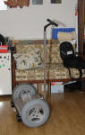
Homemade Segway Clones!
On the 30th someone e-mailed me with a link to his
homemade "Segway" pages after
seeing one of my motors on a discussion list. Very
cool to make your own if you like that
form of
transport! His write-up details the "Kalman Filter", microcontroller
and gyro sensors used to give self-balance to the system, and his
first,
second and projected third "Segway" projects: Runner I, the improved
Runner II, and Runner III - a project for some rainy weather.
| Runner II |
 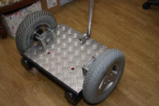
Die Plattform wurde dabei aus Alu-Riffelblech angefertigt. Die Motoren
mit integriertem Getriebe und direkt montierten Rädern
sorgen für eine größere Stabilität.
Z.Z. ist noch keine Elektronik eingebaut (15.1.12).
Hurra, Runner II läuft.
|
His site has schematics,
circuit board layouts, complete program source code for the ATMega in
'C', and
even a PDF book about the operational concepts, Das Programm-
und Filterkonzept für meinen selbstbalancierenden
Runner. - von W. Schmidt. I must confess to not understanding much
of it. (The language was beyond me!)
Even more surprisingly, it turns out this German person
had no idea where I live when he wrote me, but he's coming to see
western Canada including Victoria this July.
A Superior EV Charging System... a superior battery monitoring
system...
and an old "Derelectric" car: the 1982 Mazda RX7
J1772 EV Charging Plugs & Sockets
 It seemed galling that "EV charging Stations" were being
installed all over town, but I couldn't take advantage of them - the
Mazda has an
ordinary 120V plug, and no ordinary socket was present at any of these
charge stations. (Nor have I seen any EVs using the stations except
those belonging to the owners of the station, eg, an Esquimalt
municipal vehicle at the Esquimalt public library.)
It seemed galling that "EV charging Stations" were being
installed all over town, but I couldn't take advantage of them - the
Mazda has an
ordinary 120V plug, and no ordinary socket was present at any of these
charge stations. (Nor have I seen any EVs using the stations except
those belonging to the owners of the station, eg, an Esquimalt
municipal vehicle at the Esquimalt public library.)
It's like they're really just being installed for show:
"Look what we're doing for the environment - but hey, it's not for YOU
- Get your low-life EV out of here or we'll have it towed!"
But after getting a good look
at one at Westburne Electric [picture], I began to hope that they maybe
weren't very complex after all and could be used.
Also I realized that probably there's no line
voltage present on the main pins unless the plug and socket were mated,
for electrical safety outdoors in rain, dew or frost. This is in fact
the case: it's simple enough and the voltage is shut off until it's
plugged in.
There is however one huge problem: while the J1772
claims it allows for 120 volt charging, there is in
fact no neutral pin to get 120 volts from. I'm trying to make EV's more
practical with separate chargers on each battery. I have yet to see a
240 volt battery charger in any store, and yet
this so-called standard doesn't allow for 120 volt charging. Evidently
for the
sake of one pin on the plug, it shuts out smaller and much more common
vehicles like e-bikes and scooters, handicapped scooters, and converted
EV's such as
mine.
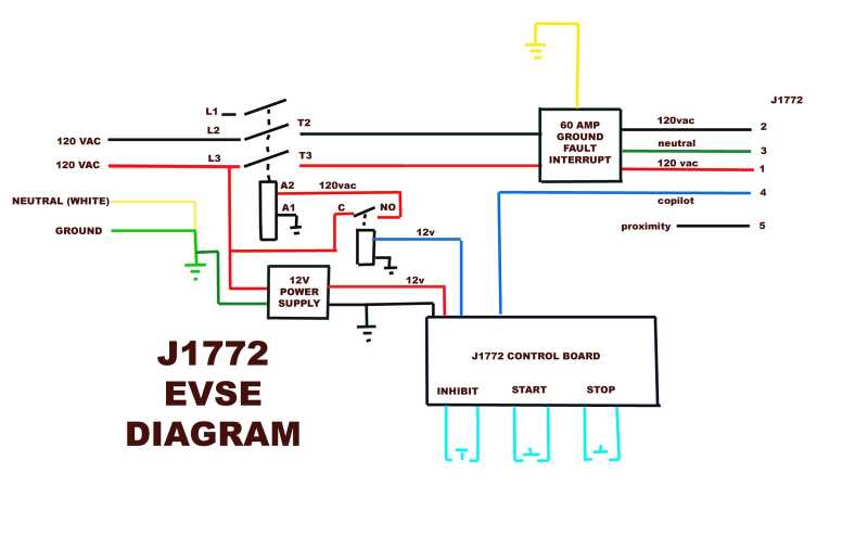
Naturally Wikipedia had an article on them. There was a
diagram of what circuits were needed for both the plug and the socket.
(It doesn't make sense - surely pin 4 and 5 are reversed on one
end... but which end?)
The article said:
J1772 signaling circuit
The signaling protocol has been designed so that:
- supply equipment signals presence of AC input power
- vehicle detects plug via proximity circuit (thus the vehicle can
prevent driving away while connected)
- control pilot functions begin
- supply equipment detects plug-in electric vehicle [PEV]
- supply equipment indicates to PEV readiness to supply energy
- PEV ventilation requirements are determined
- supply equipment current capacity provided to PEV
- PEV commands energy flow
- PEV and supply equipment continuously monitor continuity of
safety ground
- charge continues as determined by PEV
- charge may be interrupted by disconnecting the plug from the
vehicle
The technical specification was described first in the 2001 version
of SAE J1772 and subsequently the IEC 61851. The charging station puts
12 volts on the contact pilot CP and the proximity pilot PP (also "Plug
Present") measuring the voltage differences. This protocol allows it to
skip integrated circuit electronics as they are required for other
charging protocols like the CAN Bus used with Chademo or – the SAE
J1772 is considered robust enough for a range of
−40 °C to +85 °C.
The bare car side J1772
plugs cost over 100$ (ouch!) on the web, but I found a 3D printer
design to print the body for one. In the absence of any other way to
make it work, I'm going to make up a plug for the car that uses the
ground pin as neutral. I can plug the front chargers into one phase and
the rear chargers on the other to roughly balance the load - which is
under 5 amps anyway. According to the spec, the ground wire has 'ground
fault detection'. So the question is, will the breaker trip out with
the slightest inevitable load imbalance, or will it tolerate a certain
amount? I certainly intend to find out. And I'll try everywhere.
Hopefully owners will disable or somewhat desensitize the ground fault
circuit if it keeps getting tripped by people trying to charge. A
"standard" that only works with 40,000$+ cars is of little use to many
of the few EV'ers actually driving around. And the 40,000$ EV's
generally have a long range and little need to plug in everywhere they
go, whereas the 120 volters are the vehicles that really need to plug
in everywhere.
I'm somewhat hopeful that the 'ground fault' detectors
won't be very sensitive, because the body of the car is supposed to be
grounded to the wire, and that therefore the idea will work if the load
is anywheres near balanced. Cars get dusty and dirty, and they would be
almost bound to trigger a sensitive circuit in the rain. This would be
a nuisance to the charging station owners. The above Wikipedia spec
also says the car ('PEV') monitors the ground continuity, as
well as the supply equipment. This leaves a lot open to interpretation
about what the car is expected, or permitted, to do with the ground
wire.
Later I found the following diagram, which shows inside
the charging unit, with neutral and ground tied together... and on the
car socket, pin 3 is labeled neutral instead of ground.
If this isn't a mistake, current flow is permitted in a neutral
wire, and one can get 120V. That would seem more reasonable than
excluding 99.9% of battery chargers in North America, but I'm not sure
how the ground fault breaker would work, and it can't be both 'neutral'
and 'ground' in conformity with normal North American
electrical practices. But it's also unusual that neutral and ground are
tied together inside the charging unit. Who can really tell - maybe
using 120V chargers will work fine, maybe it won't. It's certainly
worth a try, since these stations are popping up all over the place.
On a final note, regular 120VAC sockets out in the rain
are dangerous
electrocution hazards. The intent of this charging system to leave the
power disconnected by a contactor until activated when a vehicle is
sensed is good. A similar system could be made for regular outlets by
having a socket with a pushbutton on it, which is pressed by the plug
on the cord as it's pushed home. However, the cord would become 'live'
whether or not the cord was plugged in at the other end, and users
would have to remember to plug the car end in first, then the cord into
the charging plug. This would still be dangerous and people would have
accidents. The button could be on a special charging cord that plugs
directly into the car, with the note "no extension cords!" or somesuch
on it.
With somewhat more effort (walking back and forth), I can
operate as safely by plugging one end of the cord in indoors where it's
dry, and plug the car end in first and unplug it last.
A "trick" that could make a safer 120 volt charger from
regular parts would be to have no actual ground wire, but instead tie
neutral to 'ground' in the car. A contactor in the charger unit would
have its coil activated when the "ground" wire in the cord was pulled
to neutral by plugging in the car. But this would be an unorthodox use
of plugs and cords that might lead to unanticipated problems, obviously
no ground fault breaker could be employed... and like regular sockets,
they probably won't be found at EV charging places.
More Mazda Miscellany
On the 4th I put in a both-sides carpeted plywood cover
over the battery well in the rear of the Madza RX7,
with a few more pieces of matching carpet surround. In addition to
looking nice and providing a cargo space, this muffled the
noise coming through the battery well from the rear axle and wheels. I
was a little disappointed by the sonic results. The rear was audibly
muffled, much quieter. But I seemed to be hearing all the same
unmuffled sounds now coming from the front, as if they had simply moved
forward to compensate. But no
doubt the sound level is
down a few dB.
Later on I noticed that it was quieter in third gear than
in second, and even quieter out of gear. That makes it transmission
noise, probably entering the car from both the front and rear end of
the driveshaft. Not much to be done about that besides insulate. People
outside the car say it's
quiet. The silence when stopped at red lights is great!
Sometime I'd like to
get the
car up on a hoist, or over a pit, to grease the suspension and steering
(it's 31 years old!). But Tom Sawyer and I managed to crawl underneath
and spray zinc "galvanizing compound" and then textured black paint on
the
rusting angle iron battery well supports at the rear, on flat pavement.
Then Tom sprayed the bumper black as well, which had various white
scrapes on it and looked pretty ugly. Another day we sprayed over the
flaking black paint at the sides of the windshield. I've done the
mechanical and electrical stuff to make it work. Tom has supplied a
couple of batteries to up the range and has done a lot of what's making
it look presentable! I presume I'll be helping him out when he gets an
electric car or a car to convert to electric, which he very much wants.
I bought an 11th
power adapter, for the 11th battery, and
on the 7th I wired it up as a float charger. It was only 3.3 amps
instead of 5, and 25$ + taxes - including a discount. I'm now paying
for having bought only 10 of the 3.95$ ones at XS Cargo instead of 30
or 40! But one can do better (than 25$) pricewise and also get more
ideal 14 volt,
6 amp
adapters, by shopping on line - worth it for several for a car charging
system.
This adapter was 15 volts, and instead of opening it, I
simply
cut the plug off the end and soldered on two diodes on the end of the
"+" wire to give a 1.2 volt
drop to the 13.8V float voltage (another 8% charging efficiency loss
right there), and then a .82 ohm resistor to limit the current when
the battery was low (more loss). I used the larger resistor since it
was only a 3.3 amp charger.
Captain's log
On the 10th I put columns on a piece of paper for date,
mileage and trip meter, amp-hours, watt-hours and comments, and I
started keeping track of my driving. Short as the trips were (the
longest one being 13 Km), I went
171 Km by the end of June, using about 32 KW of electricity - 3.20$
worth if charging was 100% efficient, but also if none of it had been
done 'for free' from the solar PV panels.
On the 12th, Rick Pitts, who had nicely converted an S10
pickup
truck came and saw the RX7. The two conversions had fairly similar
parts, so it was rather to my surprise that he was impressed by the
performance and handling. The big difference is the batteries. He lives
out of town and a 20 Km range would be inadequate. His S10 has
24 six volt golf cart batteries, which would weigh
around 1500 pounds - 3/4 of a ton. He said it's like driving a concrete
block down the road, and the brakes are only just adequate. The RX7 had
only about 450 pounds of batteries, the four NiMH'es being only about
115 pounds or so.
The weakest
lead-acid battery seemed to be getting better inch by inch - I think
with cycling, but perhaps just because of warmer weather, as suggested
by Jim Harrington. But I
wanted kilometers rather than inches, and on the 13th I changed it for
a new one that Tom brought me to use. I
put the old one outside under the wiring closet, to use with the solar
collector
system (see under 'Electric Equipment Projects').
After I got the windshield wipers working last month, I
thought they'd loosen up with use. Instead they went lethargically, had
to be pulled by hand a couple of times to get them moving again, and
then seized up again. After driving home in the rain with no wipers on
the evening of the 17th, I took the passenger's side pivot apart, with
difficulty
twisted the rod out of the pipe with vise-grips (it should have been
*loose*), filed off some rust from the outside of the rod, cleaned and
greased it,
and reassembled it all. Now they work without hesitation.
I don't get around a lot, but I drove the Mazda almost
every day and with all the electric
driving, I didn't buy gas for the Tercel from April 29th until June
22nd. Unfortunately all the money saved on gas and more is going for
extra
car insurance. It is amazing how artificial monetary factors often act
to keep us from
making the best real investments, what with having to pay extra in
order to do
the right thing, or obtaining savings, eg, energy savings, that are
trivial in monetary terms compared
to gigantic 'imposed' expenses that we may have little control over
such
as a mortgage and property taxes.
Longest drive: 13Km
On the 26th I
decided I needed the
6-tray NiMH battery from the Mazda for the Chevy Sprint experiments. I
decided to first see how much "ultimate" range the Mazda had with the
present batteries. I drove it 8.1 miles (13Km), the last mile going
around streets near home. Voltages under load went from 130's to 120's
to 110's and finally dipped down into the 100's, the lowest I've driven
them to. The CycleAnalyst showed 17.5 amp-hours - 2310
watt-hours at 132 volts. That's the most I've used in one charge. 17.5
amp-hours
doesn't seem like a lot of juice to get from batteries rated from 60 to
95 amp-hours. Part of the problem is doubtless that continuing currents
of 50 to 150 and even 200 amps are very high for regular marine-RV type
batteries. This is a less obvious reason for using golf cart batteries,
which are made to handle higher continuous currents. Battery
performance improvement with reduced currents is also a reason an
"ultra-efficient" car drive system will give a much improved driving
range.
After the trip two of the NiMH batteries were below 12
volts, eg 11.8.
They surely
had little life left. The other two were just over 12v, eg 12.1. The
lead-acids were all above 12.2 volts. If I beefed up the charging of
the NiMHs to get them up to 14.0 volts would it be good for 10
miles/16Km? Then again running lead-acids down too far with no
sodium sulfate in them is worse than running down the NiMHs. (Now 3 of
the 7 PbPb's have sodium sulfate added when new, but none presently
installed are ones 'renewed' with sodium sulfate.)
Three or four batteries were still at 12.4 volts and could
have gone a good further distance. The best battery
appeared to be the
"reconditioned" one I had purchased at Battery Doctor. It was still at
12.6 volts and so apparently could well have driven as far again to a
total of at least 16 miles/26Km.
Need for individual battery monitor
Of course, while the ever decreasing voltages can be seen
by
glancing at the CycleAnalyst while driving, there's no indication of
which batteries are dropping by how much. A manual measurement of each
battery afterwards is tedious and can only give 'after the fact'
readings. Is it mostly the NiMHs are at
the end of their charge and dropping way down under load?, or are they
doing okay
while the
weakest lead-acids are going down to 7 or 8 volts?, or are they all
dropping more or less equally? These are the sort of questions my
planned individual battery monitor is intended to answer, pretty much
automatically, while driving.
The point was acutely illustrated after a drive on the
29th. The 120 volts DC was low enough that I checked all the batteries.
I found one at 10 volts. It would obviously have been pushed much
lower while driving - into battery damage territory. In removing a
battery 3 days
previously, I had accidentally left a charger unplugged. (Wouldn't I
make a good surgeon?) The
monitor would have shown this in good time. When I turned the car on,
probably on the previous trip, I would have seen
that one battery didn't seem to be charged, and if I'd missed that, at
some point it would have
gone yellow and beeped when I stepped on the electron
pedal.
After the same drive one of the NiMHs was down farther
than the others, too. I might try to drive too far for it, too some
time -- without the monitor.
Ultrasonic Noise!
The evening after driving 13 Km, my tinnitus was loud and
piercing. Yet I had
played no music nor worked with noisy tools. It seemed to me I had
noticed this before after driving the Mazda. I looked up the PWM
frequency of the Curtis 1231C motor controller. It was 15KHz --
the same frequency as the TV flyback transformer whine that
originally caused my tinnitus when I was 6 or 7! There it was: the car
apparently makes a piercing ultrasonic sound (15KHz is ultrasonic to me
these
days) that is apparently damaging my already mediocre hearing. That
squeal would be coming off the controller, but more so as vibration of
the coils of the motor. I decided to carry earplugs in the Mazda and
use them. Another brand of controller said it was 16KHz.
In my controllers, the 'CRM' frequencies may go as high as
maybe 30 KHz. But the frequency is variable. It drops lower and lower
with motor speed and as the load decreases, and is quickly into the
audio range where its loudness can at least be heard and assessed. At
higher speeds or low loads the CRM signal may be absent. In the car
the CRM is gated on and off by PWM at around 300Hz, so it's only there
part of each second. 300Hz is audible (providing some warning to
pedestrians), but it has far less sonic energy
than 15,000.
So my controllers aren't 'innocent', and in fact the motor
coil humming will probably be heard, but they'll probably be much less
of a problem, and a less hidden problem, than fixed frequency units in
the worst "near ultra-sonic" frequency range for human ears, often more
felt as a discomfort rather than heard. With my units, no one is likely
to suffer hearing loss - without even knowing why.
120 volts better than 132?!?
The next day, the 27th, I took out the NiMH 'stack of
trays' battery to use it in the Chevy Sprint experiments. I put a size
24 battery from the back in its place. In removing one battery of
eleven, 10%, and dropping the voltage from 132 to 120 volts, one would
expect a proportional rise in the current needed to move the car.
Instead I got a surprise. When I left home, the car seemed to have more
pep, or at least no less, rather than less - if anything at slightly
lower currents. I drove 4.4 miles using
just 8.1 amp-hours - my first recorded time of using under 2 amp-hours
per mile. With the lower voltage, this translated to even more
watt-hour savings:
8.1 AH * 120 V / 4.4 miles = 221 WH/mile or 137 WH/Km.
It's hardly been below 270/170 before, and sometimes above
300/185. True, I neglected to reset the trip meter on the Cycle Analyst
before starting and the amp-hours estimate might just be slightly off,
the streets were quiet and the battery made about 30 pounds gone from
the car... but the route had the usual hills and I wasn't being
super-light with my foot.
It appeared the car had more range with 10 batteries
than with 11! Could it be that the motor or controller just runs more
efficiently at a lower voltage?
If this was verified by further 120 volt drives, I
certainly wouldn't be bothering to add another battery. Instead I might
be
trying out 108 volts again to see how the statistics stacked up. But in
the
next couple of drives I'd left a charger unplugged and couldn't trust
the rather high
figures because of the low battery. The third drive was 4.2 miles using
9.06 AH. That's 260 WH/mile, 165 WH/Km, with a very light foot on the
pedal, and the next one was 270/172. I'm guessing I made some mistake
in the first 120 volt trip's
readings. Any slight drop in watt-hours is probably explained by the
shedding of the 30 pounds of the battery.
Pipe Battery Problem (It's the chargers!... mostly)
The two newest 6-pipe NiMH 60 D cell batteries are a mix
of older batteries, some of which were in soldered together cases that
I took apart. They seemed very
good and after a drive were down to around 12.5 volts along with the
lead-acids.
But the one in the stacked cases, and the older bottom one
in the box, made of twelve 6-volt tubes, previously used in the Sprint
tests and then in the boat with Electric Caik outboard, were getting
almost as discharged as the weakest PbPb after 5 miles. The worst one
was the twelve 6-volt tubes in the bottom of the box. I suspected that
one of the sets of tubes wasn't making contact properly.
On the 7th I took the battery box apart. When I pulled out
the bottom battery I found it had not one, not two, not three, but four
end caps broken loose (two of them on the same series pair - and they
were all 'plus' ends) and only three tubes were working. Yikes! And yet
I
seem to remember testing every tube before I put the sets of 6
together, and fixing, at least, 2 or 3 of the new ones that I'd just
made. (This was the morning after thinking the voltages were getting
low
unexpectedly soon near the end of a drive, so one or two of the breaks
may have happened just within a day or so.)
I glued the caps back on and put the box together again
the other way up, with this suspicious set of 12 six volt tubes on top
where I could keep an eye on them. Some thoughts are:
- that the caps are ABS while the pipes are PVC. (There's
supposed
to be a "transition glue" for both materials in the hardware stores.)
- That it's possible but not easy to twist an end cap off when
glued with the present methylene chloride solvent, which seems about
right in case access to the cells is needed. Having them come off by
themselves, of course, is no good.
- that this battery had the pipes oriented vertically in its
original box. The means the weight of the batteries was bouncing up and
down, eg with waves on the sea or being handled roughly or dropped,
stressing the end caps.
- These particular tubes have a "U" spring of nickel-brass on the
plus end, a supposedly advantageous feature to help hold the cells
under a bit of pressure. This may have had some odd effect - maybe
there's more pressure on the caps than with other tubes.
- I think it's the first time I've had even one cap accidentally
come loose, so I think I'll just see how they all hold out now.
The next day, the 8th, this battery seemed to do okay,
while the other low one, the one in the 6-stack of 3D printed cases,
was about empty (reading 11.99 volts) on return from a too long drive.
Without knowing what it's problem was, I decided just to replace part
of it at a time and see what happened. Before dark, I pulled it from
the car and replaced the bottom tray, and the cells in the second from
bottom one. The "-" terminal of the 2nd tray seemed quite loose when I
was removing that tray. Perhaps it may not have been connecting, but
the cells in it had the exact same voltage as the others. Then I put it
back in the car and got it on charge for the night. Ideally I'd have
replaced 1/2 the battery instead of 1/3, but I now only have 20 free
NiMH D cells.
On the 10th I took a an 8 Km drive. The same two
batteries, in spite of it all, were at the end of their charge while
the other two had a few Km left in them - about the same as before. I
started thinking about upping the low ones to 70 amp-hours to
compensate.
It would at least be simple to add one more tray to the
stack of 6 - I had made it with that in mind. But I persevered and
swapped out the middle two trays with the ones previously removed from
the bottom two which had no apparent effect. Most of the trays had a
lower voltage following the drive, but one seemed to be more fully
charged. It also seemed to have a bad connection. I suspected the bad
connection was the problem.
Naturally one bad connection drops the range to less than
5/6 - maybe to 3/4 or worse - owing to the higher currents being drawn
from the remaining five banks.
The tube batteries showed no obvious problem. With the end
cap problems, probably from the push and pull on individual tubes from
the copper "springs" in between them, I might want to break up the 6v
tubes and make 6 new 12v tubes with the same cells. Those would have
1/2 as many end caps, with no special stresses on them.
Finally I put in a 7th tray, and a 7th pipe. In spite of
the theoretical added capacity, at the end of an 8.5 Km drive, they
were down to 12.0 & 12.1 volts while the other two were still at
13.3 or so.
After all that, it finally occurred to me to check
the voltages when the car was charged, instead of only after a long
drive. On the morning of the 13th the lower ones proved to be only
about 13.7 volts while the higher ones were at 13.8. That seemed to
explain the differences, but evidently none
of them were being fully charged - at least, not in 8, 12 or 20 hours.
The chargers were putting out about 14.0 volts, but into no load. Going
through the .62 ohm resistors, the charging current drops more and more
as 14 volts is approached. At about 13.8 volts, only 300mA is flowing,
or 50mA per 10 amp-hour bank, and at 13.9 volts, it's half of that,
25mA. 50mA may not even exceed the 'idle' current once charged, and so
they won't charge up to the desired 14.0 volts at all.
I changed the resistors that set the regulated voltage in
the low
pair of chargers and got
them up to 14.11 and 14.07 as measured in the lab. (It's slightly pot
luck
with no adjustment potentiometer.) As wrote about this, I considered
that I should probably raise them all ideally to about 14.15. Without
the current limiting resistor, 14.2 would be too high, but with it, the
batteries probably won't get above 14.1 or so. The resistor will
prevent excessive currents. Or, anywhere from 14.05 to 14.15, a smaller
series resistor would bring up the voltage more quickly and closer to
the set voltage. But that would need a charger either with more amps
capacity, or one that would do constant current at its maximum capacity
until it reached its set voltage.
I decided to do more measurements on the NiMH batteries,
charged and discharged, over a few days before doing anything more.
With the weak lead-acid now out, if
the NiMH's would get up to the optimum 14.0 volts, I figure the car
should have perhaps
another 3 to 6 Km of range. 12 to 15 Km will take me a few more places
than 8 or 9. 20, 25 or 30 would start making a big difference.
Then I started thinking about the 13.8 volt float chargers
for the lead-acids... maybe for the same reason those 13.8 volt charges
should be upped to 13.9 or 14.0? Some of them already were 13.9... were
those batteries the ones that were staying highest after a long drive?
At the end of all this, the NiMHs were still only charging
to about 13.8 volts, and the lower ones to 13.75.
Lead-Acid versus NiMH Float Charging
The float charging turned out to be the opposite of what I
originally expected.
The PbPb batteries charge and attain full charge at a lower voltage,
then rise up to near the 13.8 volt float charge voltage when they're
full.
Since the chargers put out their highest current, 5 amps, at around 11
to 11.5 volts, and less and less as the voltage rises towards 13.8,
the lower voltages mean they charge more quickly, in relative terms.
The NiMHs, on the other hand, rise quickly to higher
voltages at
lower states of charge, and thus they end up charging much more slowly.
8 or 10 hours wasn't enough - they were needing a whole day, and they
only seemed to hit about 13.75 to 13.85. At that the NiMH batteries
would be only
partly charged and were being drained to 12 volts while the lead-acids
still had
plenty of range left. Thus with the weak lead-acids having been
replaced by strong ones, the NiMH batteries, which should have been
great, were definitely limiting the range of the car.
Partial workaround solutions would be to set the chargers
to a
voltage
bordering on "too high" like 14.15 instead of 14.0, and to reduce the
charging resistor to .4 ohms (at 10 watts). That would mean that at 12
volts, the chargers would be being pushed to their 5 amp limit, but
would source somewhat higher currents than before as voltages rose.
As a first step to seeing the difference, I took out my
regular 6 amp battery charger that's set to 14.2 volt cutoff for
NiMHs, and started more quickly charging up the 4 NiMHs, one at a time.
Surely having all good, full batteries would provide a 20Km range! It
helped, but it too cut off without getting them fully charged - and the
voltages actually dropped again once the cells were back on 'regular'
float charge.
13.8 volts seemed to be about all I was getting.
Nevertheless on the 19th I drove 6.9 miles/11.1 Km on a single well
charged charge. 3 of the 4 NiMHs were down to 12.0 volts as measured
afterward. They may have had another kilometer or two in them above 10
volts, but no more. This didn't get put to the ultimate test. The
lead-acids were all over 12.2 volts and mostly over 12.4, indicating a
few more kilometers were available from them.
More Amps & Motor Controllers
The Mazda uses around 25 to 95 amps cruising along the
street, depending on the slope of the road. It can easily use 150 to
250 amps when accelerating or going up a steeper hill. And that's at
over 100 volts. The Electric Hubcap seems to have pretty high torque
per amp, but noting the RX7 performance, I'm considering that pumping
200 or 300 amps
into a 36 volt Electric Hubcap motor at times will be a minimal
requirement, even with an efficient transmission and optimum motor
speeds from the torque converter. I'm putting temperature sensors into
the motors, but I'm not half so concerned about the motors overheating
(the Electric Caik Outboard hardly got more than cold at 50-60 amps) as
I am about my motor controllers blowing up. Theoretically they'll take
240 amps continuous, and higher surges for short periods...
Theoretically!
Related to this, someone looked at my controllers and
pointed out that a problem with TO220 and TO247 transistor packages is
that the screw-down hole is at one end while the actual semiconductor
inside is at the other. The active end isn't being pressed against the
heatsink very well, and if contact isn't good, the heat has to travel
across the metal tab to the area of the screw before it's dissipated
into
the heatsink, so the transistor is running hotter. And as someone keeps
pointing out on the motor controller discussion list, "Heat, not
current, is the enemy." The TO247 seems better than the TO220, but
still at very high amps, thermal runaway is possible. ...and what if
that plastic around the edges isn't exactly flush with the
metal? Potentially it could actually hold the metal off the heatsink.
My early controllers from 2008, which weren't very well current limited
and might well have pushed out a few hundred amps, often burned up,
seemingly, or so I thought, from high currents causing sudden thermal
runaway.
The thermal transfer aspect of the design may bear some
investigation and measurement - or just redesign to ensure the best
attainable heat flow from that spot on the lower right where the
silicon actually is, to the heatsink. Maybe even a copper heatsink bar
under them instead of aluminum (which is inevitably aluminum alloy,
which is less heat
conductive than hard-to-get pure aluminum).
Electric Equipment Projects
Renewed
Lead-Acids for Solar Batteries
With having the 'renewed'
PbPb batteries that didn't seem to
have enough capacity to use in the car, and which nevertheless should
have hundreds of cycles in them and might well improve with use, I
decided I should use them with the solar PV system to increase the
storage capacity, which was quite small all along and had shrunk with
the loss of most of the NiMHs, now used for cars.
I decided that rather than bring the batteries into the
house and upstairs, and having to vent the closet to the outdoors in
case of gasses, I'd run a long wire to the ground and just put them
there, outside below the 12V wiring closet. I used some #14 house wire.
Rather thin, oh well - the hole in the wall was small. The bare ground
wire would be ground, the white wire (taped red) would be to the main
house supply (which is 14.0 volts in the sun, dropping to 12 or less at
night, via a
circuit breaker), and the black wire (also taped red) would be the
DC-DC converter output, also through a breaker, about 14.35 volts when
the sun is out.
Each battery would supply the main house power, but
isolated through a diode. And similarly to the car, each would charge
through a diode and a small resistor (1/4 ohm?) from the DC to DC
converter. The diode would drop the 14.35 volts to about 13.7 for the
constant voltage float charge, and the resistor would limit the
charging current for gentle charging.
It occurred to me that the place to get low voltage, high
current diodes for batteries was an auto electric store rather than the
electronics store - they have just the right ones, for car alternators.
The clerk couldn't understand wanting any number of them besides six
(the number in an alternator), so I bought six instead of four, with
the negative side being the case. That way they could all go into one
heatsink without being isolated from each other. The plus side would
come from each battery.
At ground level would be a high current diode from each
battery to the house supply cable. If the system voltage slipped below
the battery voltage less the .6 volt diode drop, the battery would
supply into the system.
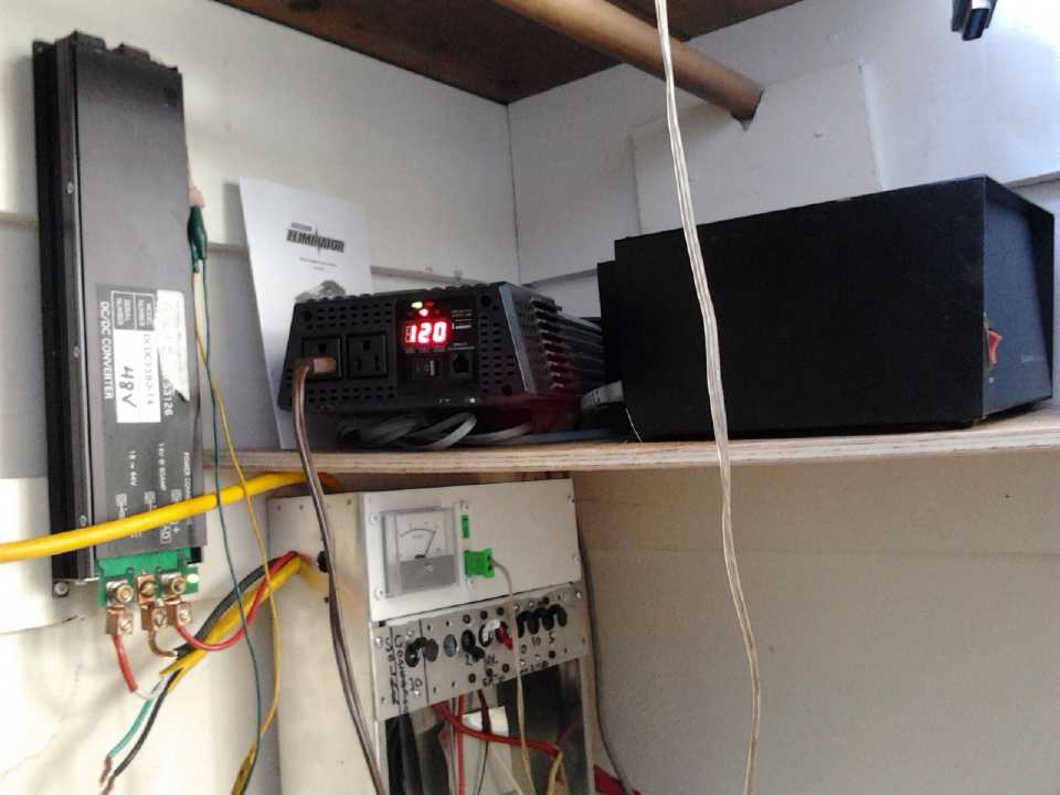
The equipment of the Solar PV System is improving.
However, so far it's all store-bought stuff and not original creations,
except for the 10" plate to mount circuit breakers on.
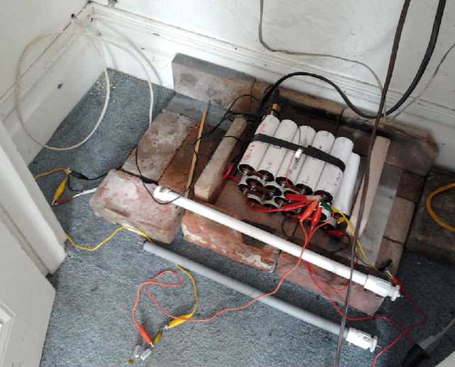
The NiMH batteries are disappearing into car projects.
The white wire through the wall is for lead-acid batteries on the
ground below.
MSP430
Microcontrollers - Interface & Software Development
You'd think in a whole month I'd have had time to
do something on this, but all I got done was to solder a few parts onto
a proto board for the fridge control. I didn't even get it wired up.
Electricity Storage - Turquoise Battery Project (etc.)
Production Prototype Cell #4 ("PP#4")
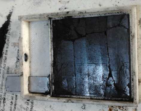
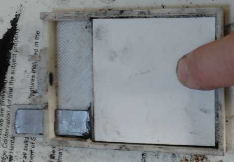
NiMn "+"ode on flexible graphite current collector, separator paper
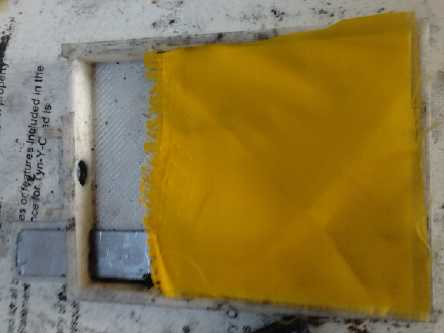
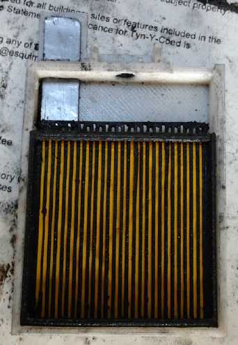
'extra' nylon separator cloth, vertical bar grille 'basket' for "-"ode.
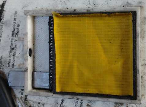
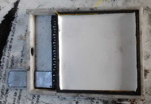
Upper nylon & paper separators
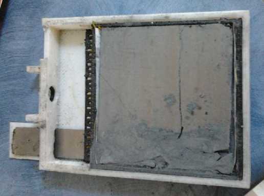
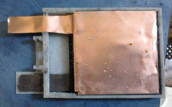
Ni "-"ode, copper foil "-" current collector
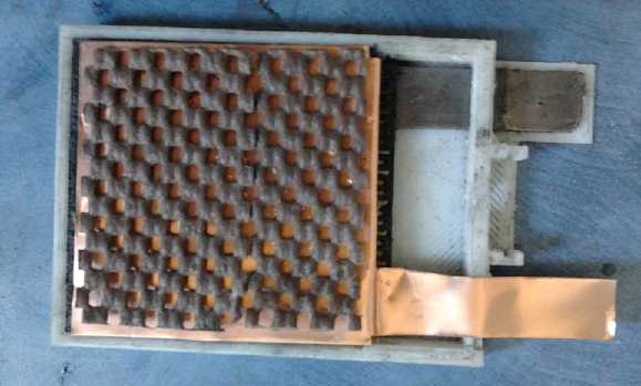
Rubbery stuff to press everything together
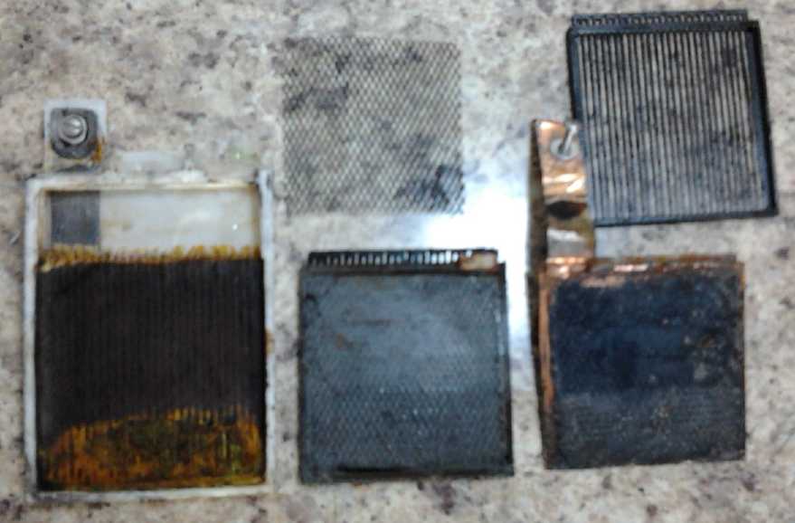
Cell, opened later.
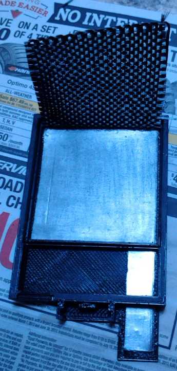
End of Month: PP#6 with carbon fiber cloth folded under osmium doped
graphite current collector sheet.
To be folded down, over electrode briquette and under separator sheets,
allowing the electrolyte to pass through
while making electrical contact points all across the front face of the
electrode to improve conductivity.
Last month battery research
by others showed use of
insoluble Barium
Ferrate. This seemed promising - what about barium manganate?
("Slightly soluble" potassium permanganate is somewhat more soluble
than I remember reading, at 6g per 100g of water. Where did my mind get
2g from?) By changing the
electrolyte from potassium chloride to barium chloride, perhaps the
manganese dioxide (MnO2, valence 4) would charge to [probably]
insoluble barium
manganate (BaMnO4, valence 6 - 2 electrons per reaction) instead of
potassium permanganate (KMnO4, valence 7 - 3 electrons per reaction).
This would seem to make the whole idea of charging to a higher
manganese oxide and moving more than one electron per reaction
definitely workable even by "regular" battery chemisty standards
without chelation.
Further reading however discloses that there's a valence 7
'barium
dipermanganate' (Ba(MnO4)2), which is very soluble. If it charges to
this instead as seems likely,
the purpose of using barium is negated.
On Sunday the 9th, after once again seeing everyone
looking for better batteries with nearly identical discussions on
"Electric Boats" and "Battery Conversions" discussion lists, plus
having been presented
with some new ideas at the end of May, I decided to
throw together another test cell.
This time, I decided that if my cells had poor
conductivity and high self discharge for reasons unknown, I'd make a
completely different negative electrode and see what changed. I decided
to use nickel, which is only -.7 volts and will yield a cell well under
2 volts. But at such a low voltage there should be no hydrogen
outgassing even if graphite is added to improve conductivity, and so it
should have little or no self discharge. I used monel powder (Ni:Cu
alloy (or 'solid solution'?), ~65:35). With the copper content,
conductivity should be high. (Reminder: nickel can only be used as a
negode in a moderately alkaline cell: it's somehow immune to oxidation
at pH 14. It's the only metal that is.)
If either or both problems were still there, it would seem
they originate in the nickel/permanganate posode. If both were gone,
the Mn
negode is to blame. At that point I could either try things to
improve the Mn negodes, or abandon them in favor of the monel. I'd
rather not do that if it can be avoided, since the manganese adds about
.7 volts more to the cell.
If the self discharge was being caused by the posode,
perhaps it might still be worth a try to replace the potassium
chloride, or some of it, with barium
chloride. I can also try some ferric chloride, a strong oxidant, but I
discovered that has to be mixed into the electrode, not added to the
electrolyte later.
Another point to the new cell is that "PP#3" suddenly
'went bad'. Up until that point, its performance had been gradually
improving with each cycle. In "PP#2" there didn't seem to be much left
of the separator paper when it was disassembled. Apparently #3 had the
same problem, because when it went bad, electrode powder material came
out the filler hole when the electrolyte was drained. (Yes, I really
ought
to rip it apart and look.)
My remedy is to add a layer of thin 100% nylon cloth in
front of each each paper. The paper won't let even minute particles
through, and the cloth will support the paper at all points even if it
has more or less turned to mush.
Another and rather risky change I made was to use PLA
plastic for the cell body instead of ABS... and without even verifying
first that methylene chloride ("MC") would glue it! The intent here was
to use a plastic that hopefully wouldn't wick the water up the sides to
the filler hole. The PLA proved to be MC proof and the face cover
easily popped off. I waited until Monday to go to Industrial Plastics
and get some MEK to try instead. It worked, but the bond wasn't very
strong.
The posode was made with the same mix as last time (was
that from March?). That ran out without filling the compactor, and to
finish I used an older previous mix having MnO2 instead of KMnO4, to
which I
added some monel powder to get a bit of granularity, and some KMnO4.
These were wetted with Diesel Kleen, compacted (about 1/2 of each), and
the electrode placed in the cell. Its resistance was moderate, in the
lower 100's of ohms from any surface point to the graphite current
collector.
For the minus I used 40g of fine monel powder (still sort
of coarse & granular for battery work) to which I added 3.5g
graphite powder to hopefully improve conductivity (which should be good
anyway), and 5g of nickel hydroxide to get some fine nickel in the
voids between the granules. There was no need to add transition metal
compounds to raise the hydrogen overvoltage since the reaction voltage
of the nickel, -.5 volts or so, is lower than the base hydrogen
generation voltage. So common things like graphite and a copper foil
current collector should work fine. (A sheet zinc current collector
here would oxidize since it has a higher reaction voltage than nickel.)
The electrode used all of the mix - it was the right amount.
But I should have used more graphite - resistance was in
the K ohms. And the effect of compaction was apparent. There were about
5 fills and compactions making 5 visible 'bands', and the different
bands had different meter probe contact resistances from the lower 1K
ohms to over 20K ohms. This was all high, and varied doubtless from
uneven compaction.
The cell didn't perform well. On the 14th I opened it up.
The MEK didn't glue the face on very tightly, and I slit it open
without damaging the insides. Also I had realized that with the new
design there was no reason to glue the internal basket in, making it
removable.
Underneath, the soft, tough watercolor separator paper of
the posode appeared to have become a very brittle sheet with yellow
colors, probably sulfates. That wasn't an expected part of the plan.
But it probably explained where the yellow and orange crystals on some
of the [leaking?] terminals
came from - the paper, and probably the sulfates in the Sunlight
dishsoap.
On the 17th I removed the negode from the tray, ground it
back to powder (it broke up easily), and added 10g of graphite to its
46g. The graphite seemed to be more bulk than the electrode material,
but after I compacted it back into the square, only 11g of material was
left, and it didn't look like much bulk. This time, negode resistance
readings were in the mid tens of ohms between any two points. That was
more like it!
I also poured a little ferric chloride into the posode. It
bubbled fiercely for a brief time. Unlike rather inert ferric oxide
(rust), ferric chloride is a strong oxidizer. And I rinsed off the
separator bars area. It was surprisingly dirty for a zone that was
supposed to be clean with no powders leaking into it. It's possible
that crud
between electrodes could explain all the self discharge problems - if
this has been regularly occurring. Note to self: once a battery is
assembled, don't squeeze it, even if discharge currents seem to
increase a little!
This time, I decided to assemble the battery simply by
clamping it between two flat plates of metal, with a piece of rubber
for the face instead of plastic, and simply leaving the four C-clamps
on - it's a test cell after all. No glue except some modeling clay to
attempt to seal the electrode terminals. Then it would be simple to
open, and anything can be inspected, cleaned or replaced. It proved
impossible to stop the leaks, but I just kept pouring in bits of salt
solution to keep it from getting too dry.
On the morning of the 18th the smell of diesel kleen was
pretty much gone, and I put it together, with a new piece of nylon
cloth in the positive separator side. It started out apparently
discharged at .6 volts and it would supply virtually no current. With a
35mA
charge, it charged up to 1.7 volts or so quickly, then gradually rose
and fell, hitting a peak of 1.800 volts. Then it started falling to
around 1.73 volts. That this was owing to electrode conductivity
increasing as it charged and not some increasing self discharge seemed
indicated by the voltage when momentarily disconnected staying higher
and falling more slowly with time. However, currents were only somewhat
higher, and the cell still didn't perform much like a 'real' battery.
It completely discharged itself overnight. But the next day I took it
apart and rinsed it, charged it a few hours, and gave it a discharge
test with a 50 ohm load. It looked pretty hopeless with quickly
dropping voltages, but it started to level out at around 1.25 volts,
and then started dropping much more slowly. This sort of voltage didn't
make much sense for KMnO4 discharging to 2 MnO2 (with the Ni negative
discharging to Ni(OH)2)... but it was about right for MnO2 discharging
to Mn2O3. It hit 1.0 volts in 1/2 hour, and continued dropping about
10mV per minute down into the .7 volt range for an hour. That would
probably be the negative continuing to make Ni(OH)2, with the positive
going from Mn2O3 to Mn3O4 and finally to Mn(OH)2. But it was all
milliamp-hours instead of amp-hours.
Self Discharge Changes With pH!
It finally occurred to me to check the pH. It was 6. At
that acidity, many things that are insoluble above pH 8 become soluble,
so crud saturating the separator paper and self discharge would be
expected. Aha! I dumped in some calcium oxide to raise the pH to 12 or
13 before trying to charge the cell again.
Low pH in general, even 8, 9 or 10, might explain
a lot.
There's the "predominant species" - hydroxides - then there's what else
might be floating around in small quantities that might have untoward
effects. Perhaps the pH really needed to be kept up to 11, 12 or 13...
or (perish the thought!) 14 to prevent the self discharge I've been
having all along. Having thought of it, I checked out
alkalinity versus self-discharge.
Sure enough, 3 hours later, when the charge was
disconnected
the voltage dropped from 2.3 volts to 2.08, and there came almost to a
standstill as far as immediate observation. Considering only trace
additives or trapped hydrogen could cause such high voltage, it was a
dramatic reduction.
When I tried a load test after this relatively short charge period,
voltages started out higher and stayed higher until about the 16 minute
mark.
Why have I never thought of or noticed a correlation
between pH and self discharge before? Well, after all the standard dry
cell (non alkaline) is low pH, and it holds a charge very well.
However, staring at a voltmeter
and leaving the cell overnight were two different things and as usual
most of
the charge was gone by morning.
Also to check out self discharge factors, I decided to
make a new posode with entirely traditional stuff:
* nickel hydroxide (15g),
* with graphite for conductivity (7.5g),
* samarium oxide to raise oxygen overvoltage(2.1g),
* and 1% CMC gum for binder(.5g).
Nickel hydroxide electrode with the paper peeled
back.
Far left is the negode with a copper grille on the back.
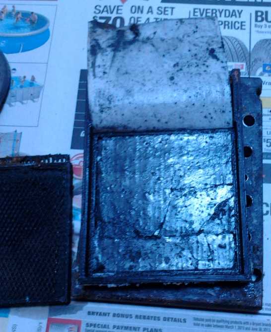 This
made an electrode with a bit to spare. The only
non-traditional part was wetting the mix with toluene to dissolve the
graphite to have it reform into more conductive forms - nano-tubes and
lamilae - as the liquid evaporated. (I used toluene [methyl benzene]
just in case the diesel-kleen [with tri-methyl benzene] has been
leaving anything behind after evaporating, causing the self
discharge.) I also omitted the Sunlight dishsoap with its sulfates and
sulfonates. Theoretically - my theory - not chelating the metal ions is
what gives electrodes their limited cycle life and chelation makes them
permanent. But after all my poor results, this time I want to try
things more in accordance with things that have worked in the past. The
new nickel hydroxide electrode (June 19th) had the silvery color of
reformed graphite
and was around 250-400 ohms between various points if the meter probes
were dug in a bit.
This
made an electrode with a bit to spare. The only
non-traditional part was wetting the mix with toluene to dissolve the
graphite to have it reform into more conductive forms - nano-tubes and
lamilae - as the liquid evaporated. (I used toluene [methyl benzene]
just in case the diesel-kleen [with tri-methyl benzene] has been
leaving anything behind after evaporating, causing the self
discharge.) I also omitted the Sunlight dishsoap with its sulfates and
sulfonates. Theoretically - my theory - not chelating the metal ions is
what gives electrodes their limited cycle life and chelation makes them
permanent. But after all my poor results, this time I want to try
things more in accordance with things that have worked in the past. The
new nickel hydroxide electrode (June 19th) had the silvery color of
reformed graphite
and was around 250-400 ohms between various points if the meter probes
were dug in a bit.
I don't know why, but I opened the cell, hoping to put the
new electrode into it. It would have been better to first simply add
enough
potassium hydroxide to the electrolyte to raise the same cell pH to 14,
and see if that helped. Could my
whole idea of a "moderately alkaline" electrolyte be flawed? Anyway, it
doesn't take much KOH added to salt
solution to raise the pH to 14, and I still think the main electrolyte
can be KCl, potassium chloride, which will still be much safer than
pure KOH owing to the much lower concentration of hydroxide ions. And
of course NH4Cl
doesn't discharge standard dry cells even at low pH. (But I wonder why
they use NH4Cl instead of KCl?)
Trying to get the posode out broke up the graphite current
collector. Oh well! I took another case and put in a new graphite
sheet, separator sheets, and the basket still holding the nickel
negode. ...In case nickel will work at pH 14 with the chloride in the
electrolyte. According to Hoyle, at pH 14, it should be just a 1.1
(nominal) volt cell. It definitely didn't want to charge up to the sort
of voltages of my permanganate cells, sitting at under 1.4 volts on
charge.
This cell now, PP5, had the usual low conductivity on the
first try... and it got worse after that. And it still lost most of its
charge overnight. Alright then, what about Ni-Fe at pH 14?. If that
didn't work...
Back to PP #3?
In some e-mails with someone else who's having trouble
making batteries that perform acceptably - NiFe in his case - I started
thinking that I should try the same formula as cell PP3 (TE News #62).
That one seemed to be working and gradually improving for a couple of
weeks until suddenly it failed. Probably one of the separator papers
gave way and allowed electrode material to leak between electrodes.
Three things I'll change: (1) add some cloth separators (nylon?) to the
paper ones to help hold things together. (2) Shorten the torching of
the negode. I think 7 or 8 seconds of torching oxidized it too much,
reducing the conductivity and performance, resulting in the poor
initial performance. I don't like reading 200 ohms before torching and
200,000 afterward. (3) Put a carbon fiber cloth next to the posode,
under the separator sheets - see below.
I mentioned to him, and should do so here in case I
haven't mentioned it in
some previous newsletter: the idea of chelating the slightly soluble
KMnO4 with sulfates and sulfonates (in Sunlight dishsoap) to prevent
the MnO4- ion from migrating appears to work. The evidence for this is
that the electrolyte initially turns purple with permanganate
(obviously a little gets away), but then it clears up, indicating no
more permanganate in the electrolyte. But if the posode is later broken
apart and wetted, purple permanganate comes out into the water,
indicating that it's still present in the electrode. (The initial
dissolved permanganate probably hits the negode and goes through the
whole charge sequence MnO4- -> MnO2 -> Mn2O3 -> Mn3O4 ->
Mn(OH)2 -> Mn metal, adding a minute bit of Mn substance permanently
to the negode - which is of little consequence if it's Mn anyway.)
On the 28th I put in the collector sheet with an edge of a
carbon fiber mat tucked under it, and made the posode. I used nearly
the same mix of chemicals as for #3 (TE News #62), compacted as hard as
I could. The
resistance point to point was just 20 to 30 ohms. I put it in, folded
the carbon fiber on top of it, put in watercolor paper and nylon
separator sheets, and pressed the upper basket down on top. But I
didn't finish the cell in June.
Carbon Fiber separator sheet to improve electrode conductivity
What happens if the posode separator sheets are three: (1)
carbon fiber, (2) paper, and (3) nylon? The carbon fiber would help
connect any low conductivity areas in the electrode by connecting the
whole face area together. I decided to immediately try this in the
present cell with its low conductivity nickel posode. I took it apart,
and found that the paper was in good shape. It must be the Sunlight
dishsoap I usually add that suffuses them and makes them brittle. It
also was only stuck to the electrode in a couple of spots, so I got it
up pretty easily. That doesn't say much for holding the electrode
compressed, which probably explains its decreasing conductivity. I
didn't think to check electrode surface resistances, added the carbon
fiber matt on top of the posode, and put it together again. It would
doubtless be ideal to wrap the cloth over the electrode edge on one
side and have it press on the current collector sheet, but I couldn't
do that without pulling up the electrode and probably wrecking it.
The cell worked better again,
whether from the conductivity of the carbon fiber or simply because its
thickness pressed the electrode together better, I'm not sure. Probably
both. I looked for a thin carbon fiber cloth or non-woven fiber to
continue using this little trick, but the plastic place only had more
of the same as I had, 50mm, 100mm, 150mm or meter+ width. After all,
low conductivity is one of
my main problems. I wouldn't trust a fine carbon fiber cloth not to
leak powder or short to the other electrode across the vertical grill
space. Otherwise it would be a theoretical possibility to have no other
separator sheet.
NiNi, continued
To continue with this NiNi cell: this time it didn't seem
to leak. (yay!) pH seemed to sit around
12-13. It seemed to charge up to
about 1.45 volts, and with 50 ohm loads it ran down to 1.0 volts in:
50", 70", 90", 4'30", 11', 17', 16', 15' on seven tries. As usual:
hours
of low rate
charge, milliamp minutes of discharge. After about the 5th load test,
it seemed it would now go up or down in voltage only depending on how
long and how
hard it was charged.
On July 1st, after charging all night at ~30mA, it started
at over 1.7 volts open circuit and lasted 22':45". This time I left it
going, and found that opposite to most Ni-Xx cells, the steady
30mV/minute voltage drop had started slowing somewhere around 1.15
volts, and it slowed dramatically under a volt to 10, 6 and finally
4mV/minute. The cell ran another 50 minutes before it was down to .75
volts. I ran it for 2 hours total, down to .636v, where it was dropping
at just 2mV/minute, still putting out over 12.7 mA into the 50 ohm
load: total about 30mA hours. It ran even longer
down to 5.3 volts - 4 hours and around 55 or 60mAH, still working (if
1/2 a volt is useful). The voltages being so far below the
theoretical voltage of Ni-Ni (1.2v no load) is probably attributable to
high internal resistance, but then it didn't recover very far after the
discharges. The question seemed to be not why it worked
well at low voltages, but why Ni-Ni should charge up above about 1.3
volts or so in the first place.
The initial high voltage was probably hydrogen ions or gas
trapped in the negode, forming a nickel-hydrogen cell. This is
supported by bubbles seen on the surface and a lowered
electrolyte level noted later. Once the hydrogen was exhausted and as
it fell
under 1.2 volts or so, the Ni-Ni chemistry became active.
Ni-Ni chemistry is probably 'perpetual'. Whereas metal
hydrides gradually corrode, iron gradually over-oxidizes and turns to
non-conductive rust, and cadmium and zinc gradually dissolve or form
crystals that short out the cell, discharged and even overdischarged
nickel can be charged back up to metallic state and there would seem to
be no soluble forms. And it's just .1 volts lower voltage than the
other Ni-Xx types.
However, a Ni/Mn - Mn cell, PP#3, gave 100mA-hours at
double the voltage of Ni-Ni in March. It was on the borderline of
being a useful cell. Furthermore, until it suddenly 'went bad', it
appeared to be improving gradually with each cycle. I think I'll go
back to that chemistry and see what improvements I can tweak out of it.
With a few times improvement it would make a good cell, where this NiNi
cell would need at least 20x and twice as many cells would be required
to get a desired voltage. I may first try Ni-Mn using the Ni posode of
and in this cell with an Mn negode. When I take it apart, I'll try to
check its surface resistance (carbon fiber cloth permitting) and see if
it seems worth it.
And I really should find out for sure if graphite and
graphite powder cause hydrogen bubbling and self discharge of Mn
negodes. If not, why am I using a zinc current collector sheet and zinc
powder as a conductivity additive? If the carbon fiber separator sheet
could be used on that side, too, it would doubtless make for a good
improvement in conductivity. If that doesn't work, I could perhaps make
a
perforated zinc sheet - see next.
Making holes in metal for perforated metal electrodes - a technique
An e-mail correspondent suggested a technique that sounds
great for perforating metal: silk screen a mask with tiny holes onto
the metal and etch it in acid, much like making a printed circuit
board. Naturally I would do the laser printer toner transfer for the
pattern. Both sides would of course need screening and there may be a
complication or two, but without having a special punch to do it, it
just might be the practical way. I should think zinc would erode pretty
fast in acid.
Pursuant to that, someone said a faster way to etch
circuit boards is to soak a sponge in the etchant and repeatedly wipe
the board with the sponge, wearing rubber gloves (and eye protection)
of course. The trouble with all the bath methods is that the waste
product builds up on or at the copper and stops the reaction until it's
washed away by agitation of the bath. The sponge continually wipes off
the byproduct. I'll hazard a guess that it only takes 4 or 5 minutes
(for a circuit board) instead of 15 , 20, 30 or more.
http://www.TurquoiseEnergy.com
Victoria BC