Turquoise
Energy Ltd. News #66
Victoria BC
by Craig Carmichael - August 2nd, 2013
www.TurquoiseEnergy.com
= www.ElectricCaik.com
= www.ElectricHubcap.com
= www.ElectricWeel.com
Feature:
Permanganate-manganese Battery Breakthrough! High voltage, high energy
cells now work consistently and should hold their charge.
Month In Brief
(Project Summaries)
- Electric Mazda: batteries again - MnMn: Best Battery Chemistry
Ever! (the short version!) - Wiring up PbPb interface to solar PV
system - Evacuated tube with ammonia test seemed to work except it
leaked - a couple of better photos of the Electric Hubcap motor.
In Passing (Miscellaneous
topics, editorial comments & opinionated rants)
- continued erosion of financial system - USA war on journalists claims
another one - Cassini photo: Earth as seen from Saturn
Electric Transport - Electric
Hubcap Motor
Systems
* Turquoise Motor controller realizations: 80 amps DC means maybe ~240
amps
peak with a motor stopped or at very low RPM,
helping to explain why I can't seem to get higher currents without
blowing dual 120 amp rated mosfets.
Other "Green" Electric Equipment Projects
* Summer Thermoelectric Fridge Notes: It's struggling to keep cool in
the heat. More insulation helps.
Electricity Generating
* Wave Power for Boat Propulsion?
Electricity Storage - Turquoise
MnMn Battery Project etc.
* Calcium hydroxide
prevents gassing on overcharging.
* MnMn chemistry & construction seems "good enough" for solar use
if "prismatic" constructions are employed.
* MnMn never "dies": the voltages just keep gradually getting lower.
* Theoretically infinite cycle life.
* Electrode compaction with
hammer works if there's no press.
* Simple cases that don't leak for stationary applications! -- wide
mouth jars, plastic or glass.
* Low temperature is the key to charging manganese to metal, and to it
holding its charge. Cool room or fridge works.
* -Mn additive: zirconium silicate raises hydrogen overvoltage - Now
cells work at 'normal'
temperatures!
* NiMH pipe battery Connection
Problem Tracked Down -- beware of
unspringy, high resistance
spring clips in battery tubes!
No Project Reports on: DSSC
solar cells, LED Lighting, Pulsejet steel
plate cutter, Magnetic
Motion Machine,
CNC Gardening/Farming Machine (sigh, maybe summer 2014?),
Woodstove/Thermal Electricity Generator, Peltier & vacuum pipe heat
pumping.
Newsletters Index/Highlights: http://www.TurquoiseEnergy.com/news/index.html
Construction Manuals and information:
-
Electric Hubcap Motor - Turquoise Motor
Controller - 36 Volt Electric
Fan-Heater (say, this heater is now obsolete! Use Peltier module heat
pump!)
- Nanocrystalline glaze to enhance Solar
Cell performance - Ersatz 'powder coating' home process for
protecting/painting metal
Products Catalog:
- Electric Hubcap Motor Kit - also please inquire about Electric
Caik
3KW Motor Kit
- Sodium Sulfate - Lead-Acid battery longevity/renewal
- NiMH Handy Battery Sticks, 12v battery trays & Dry
Cells (cheapest NiMH
prices in Victoria BC)
- LED Light Fixtures
Will accept BITCOIN digital currency
...all at: http://www.TurquoiseEnergy.com/
(orders: e-mail craig@saers.com)
Permanganate-Manganese:
Best
Battery
Chemistry
Ever!
Key to manganese metal charging & holding charge: cool temperature.
My Cells - Good Enough for Solar Energy Storage?
(A short version of this story is in July in Brief,
below, for busier readers)
At the start of July, there
seemed to be still three longstanding major problems preventing
practical use of my cells:
high self discharge, low current capacity and low active substance
utilization of the permanganate-manganese
electrodes and cells.
I did more
new chemie battery making
work than I'd planned, but by the end of the month some key questions
had been answered. By about the 20th I decided I had practical
batteries at
least for low rate solar applications... by modifying my expectations
rather
than the chemistry. Then on the last day of the month I discovered a
key factor in my mixed results and high self discharge in charging
manganese to the metallic state: it worked at cool temperatures but not
at warm summer temperatures. That's how close Mn is to having the
highest possible voltage and energy that can be held in an aqueous
battery. On August 2nd I decided to try another additive to raise the
hydrogen overvoltage, zirconium silicate. It worked! The batteries
charge readily at 2.9 volts to hold 2.5 volts and above as tested at
29°c. It hadn't taken enough charge and there wasn't time to do an
hours-long self discharge test before sending this newsletter, but it
would appear the cells will now work acceptably, at 'normal'
temperature ranges.
This is fabulous of course! -- It appears I've
accomplished one of the main objectives set in 2008 -- a higher
voltage, incredibly high energy density aqueous battery! But it led to
some last minute
newsletter revisions, and there are some somewhat inconsistent writings
within
this text crossing paths with each other.
Usually I stop load tests when the voltage drops lower
than seems reasonable, eg, at 1.75 or 1.5 volts for a 2+ volt cell. And
the low
amp-hours are usually disappointing. But I ran a
long 50 ohm load test on cell PP#6. The voltage dropped very rapidly at
first, maintaining 1.75 volts for under 20 minutes, and usually I'd
have shut it off there and said "fooey!" But I left it on, and it put
out
good current for a full 24 hours --
22 of
them at voltages below 1.5. Total transfer of electrons from '-' to '+'
was over .55 amp-hours. Even
then it was putting out and the voltage drop had become very gradual.
But it was down to .885 volts. It might
have run even another whole day at even lower voltages and passed an
amp-hour. Cells PP#2 and PP#3 held
higher voltages longer - eg, 1.75V for 2.5 hours - but below that point
they too must have
had the bulk of their
charge still remaining.
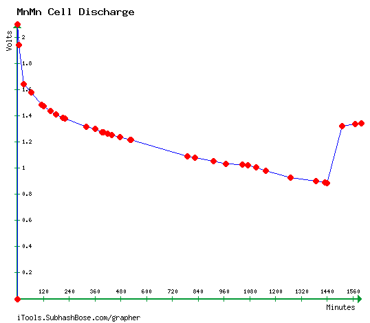
50Ω discharge test of cell PP#6, starting just over 2 volts and hitting
.885 volts after 24 hours.
When the load was removed it recovered to 1.34 volts - probably with
Mn2O3
in the "+" side.
(This is rather similar to a chart done in March 2012 when I first got
the chemistry working
[TE News #50], but I didn't run that test long enough to see the
changing valence states.)
BTW the graph software at the indicated link is very nice: enter your
x,y values into a text file,
then go to the site, upload it, enter a few things, and download the
graph image.
(I had to enter one dummy value at zero to get the graph to start at
zero
volts instead of .885.)
I
started to re-think how a
battery is expected to
perform. We're used to seeing battery voltages that may vary by 10 or
20% - perhaps 30% at the outside - between full charge and low. But
people talk about
"ultracapacitors" to hold energy with ridiculously variable, constantly
changing output
voltage. This is supposedly to be compensated for by elaborate
electronics. What's wrong then with a high capacity storage battery
that
goes down to 1/2 the fully charged voltage before it's considered
spent? If that's too much variation for the intended use, we have DC to
DC converters that can easily handle such ranges, and output a
regulated
constant voltage. Or it could be charged just to 1.9 volts (to MnO2 but
not to KMnO4) and use terminated at 1.3v or wherever.
If lower
cell voltages were considered acceptable I could
cross "low substance utilization" off the main list of complaints. And
perhaps "high self discharge": it ends with decreasing
voltage. A cell that won't hold over 2 volts overnight might hold
around 1.8 volts, still accounting for much of
its total
charge, for weeks - contrary to appearances, the cells still have lots
of stored energy. As a
battery from which only 1 to 1.6 volts is expected (varying
considerably with state of charge), only
the low current capacity is a major objection. Perhaps I'd
created great low-rate energy storage batteries without realizing it?
There's no apparent reason to think that a manganese cell
won't continue working 'forever'. It's the
amazing electrochemical element that can, with chelation of potassium
permanganate, moderately alkaline pH, antimony sulfide to raise
hydrogen overvoltage, and (evidently) a cool temperature, charge in
either direction from
valence 7 (permanganate) through various oxidation states to valence 0
(metallic particles) or from 0 to 7, without at any point becoming a
passive
insulator,
dissolving, or rapidly self discharging.
Changing oxidation states is where the amp-hours get
multiplied, at the expense
of having a more variable voltage than other cells with single
reactions. Here I'll refer
back to a chart I made over a year ago for its general idea of the step
voltages:
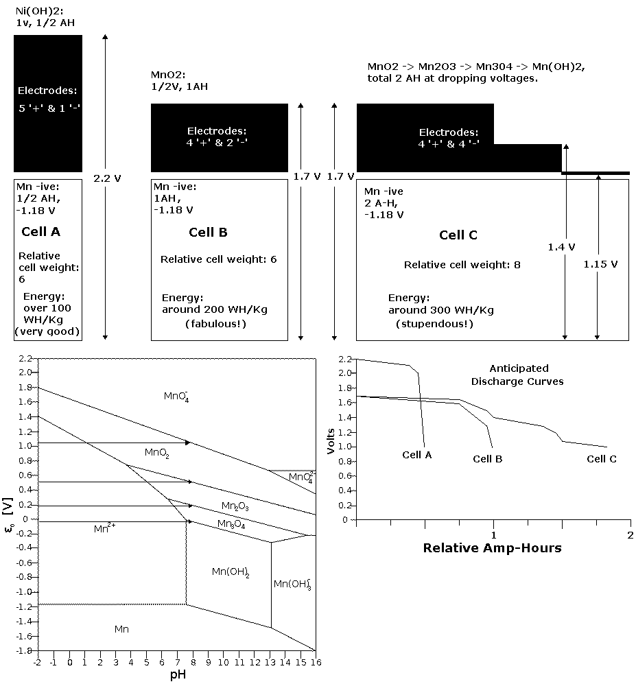
(Arrow for valence 7, "MnO4-" voltage added)
(The amp-hours per kilogram values assume high utilization of the
active materials and
constructions without
excess weight and water. To actually get 20% utilization,
in jars of water, would be okay for solar/stationary uses.)
Apparently I had the right idea then, shortly before I
realized the cells were charging to permanganate, which led me to put
the lower
oxides out of my mind. For the actual posodes I chose a mix of
manganese and nickel (~60:40). If the nickel oxyhydroxide and the
permanganate or nickel manganate do hold their high voltage charge, one
has roughly the equivalent of cell "A" added to the left side of cell
"C". If they
don't, one still has cell "C".
Some expert will doubtless say here that manganese metal
as a negative is known to spontaneously discharge itself within an hour
or two. But that's at pH 14
where its reaction voltage is highest (-1.57v), and with no additive
such as antimony
sulfide to raise the electrode's hydrogen overvoltage. The reaction
voltage of metallic manganese evidently drops faster between pH 14 and
pH 7.5 than the hydrogen overvoltage does, so my theory has all along
been that there's a "moderately alkaline" range where it can stay
charged if sufficient overvoltage raising can be attained.
Of course the -Mn voltage, in pushing the limits of the
amount of energy that can be stored in an aqueous negative electrode,
does also push the limits of chargability, and some of my cells held
their charge better than others. Reviewing TE News #50 from when I
first got
permanganate-manganese cells working, I noted that a test cell with a
'pure
manganese' negative held 2.13 volts for 24 hours. That's 'good enough'
for solar use, since it gets recharged daily. I recall cell PP#3 also
maintaining over 2 volts overnight on at least a couple of occasions.
These would be pretty high voltages to account for unless the
Mn negative was holding at least some metallic charge.
But in PP#6, the Mn negative wouldn't stay charged above
about 1.8 volts overnight -- the voltage for the Zn additive, not the
Mn.
That's not the best. It gave the .55 amp-hours, and it's good enough to
use if the 20% concentration of zinc doesn't form dendrites and short
the cell. (This does seem probable, especially given the lower pH where
the Pourbaix diagrams show no soluble state... if one can trust that.)
I stirred in some hydroxide [Ca(OH)2 & KOH] to
alkalize the electrolyte from about neutral to a higher value and the
charge voltage quickly went up 30mV, but it didn't help get the Mn
charged to metal.
The cells that worked were done in winter and spring. This
is summer. The temperature in my house isn't well regulated. Could
temperature (23°c that day) be the reason? I put the cell in the
fridge (8°) and continued charging it. By morning its voltage was
up to 2.45, much the highest yet, and it held something like 2.15 volts
open circuit for around an hour
indicating Mn metallic charge. I
took it out of the fridge and left it on charge several hours
(22°c), but the voltage dropped to 2.4 and when the charge was
removed, the self discharge was about 6 times faster dropping through
the 2.18 volt area (1mV drop per 5 seconds instead of per 30 seconds).
Apparently it works much better in a cooler. I put it back in and back
on charge, and it passed 2.5 volts by evening. The charging current had
dropped off with the higher voltage, and I put in a smaller resistor to
bring it back up to 25mA. It hit 2.68 volts after a day, holding a
while over 2.3 with the charge off.
Once much of the manganese has charged to metallic state,
higher cell conductivity may be expected, reducing or perhaps
eliminating the last major electrochemical problem with the cells.
Whether it can work at room temperature and above would be
a subject for further experimentation. Probably continued practice and
experimentation would disclose and hopefully raise the fine edge
between
manganese gaining and holding its very energetic charge, and not.
On August 2nd I decided to try an identical electrode but
with 3% zirconium silicate as an overvoltage raising additive before
sending this newsletter. Like the calcium dioxide on the
positive side, the reaction voltage of zirconium is just a bit too high
to retain a charge. It might interact favorably with the manganese.
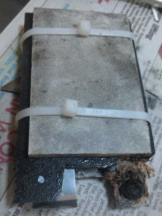
I made it, pried open cell PP#3 and replaced the negative
electrode. I stuck a back on it, strapped it on with cable ties, and
put it in the jar in place of PP#6.
It worked. In a test at 29°c (dropping gradually to 26
as the bucket of water now holding the battery jar cooled) the cell
attained a charge voltage of about 2.9 volts after a few hours and held
2.4 volts for 1/4 hour. It was obviously going to go higher when the
charge was put back on, and this result will surely be found to be
replicable.
Permanganate-manganese batteries are now a viable battery
type, and a
higher energy aqueous battery can scarcely be imagined.
Even when the cells
hold a 2.4+ volt charge, much more energy is still available at lower
voltages as the permanganate becomes manganese
dioxide and progressively lower oxides. 5 or 6 cells will give a fine
12 volt battery, but one that can be run down to perhaps 8 or 9 volts
still happily putting out power instead of rapidly dying if it's called
on to "work overtime"...
and sit at any state of charge for any length of time with no damage or
loss of 'forever' cycle capacity.
A bonus chemistry feature is a
calcium hydroxide layer painted onto the positive current
collectors. Instead of bubbling oxygen if overcharged, the calcium
charges to dioxide, CaO2, or perhaps
one might say "calcium peroxide". The energetic voltage (+1.55 volts)
of this substance will spontaneously discharge it back to Ca(OH)2,
releasing hydroxide ions to discharge the negative electrode, so that
the excess charge discharges itself (making heat) without generating
hydrogen gas - or at least less of it.
The present low current capacity cells
seem
pretty hopeless for high current electric transport applications... but
they are real batteries, and the long load test shows they hold
very useful amounts of charge.
For stationary, low rate solar PV use, poor performance can be overcome
by making cells with as much electrode substance as it takes to get the
desired
power and storage capacity. The cells yield good amp-hours if driven
from
their fully charged state down to 1 volt or lower. If
necessary they can be tied in with flexible input DC to DC
converters to supply a constant voltage.
Hopefully also the performance
will
improve with time, practice, and
figuring out better ways to do things. They also seem to improve with
cycling, and more testing of this aspect is required.
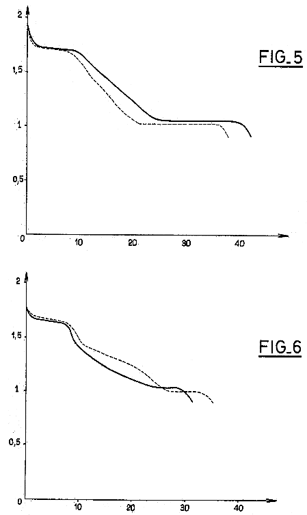 On the 28th, I
ran across an interesting patent from 1985. It was for a
graphite-manganese chloride compound for battery positive electrodes.
It had much in common with PP#6. Fig.5 from the patent showed the
discharge curve of a cell with this and a zinc negative. The voltages
obtained were rather similar, and the performance improved from cycle 1
(dotted) to cycle 4, as my cells have done. They also noted some
charging to permanganate, and also that their electrode substance would
work at any pH from acid to alkali.
On the 28th, I
ran across an interesting patent from 1985. It was for a
graphite-manganese chloride compound for battery positive electrodes.
It had much in common with PP#6. Fig.5 from the patent showed the
discharge curve of a cell with this and a zinc negative. The voltages
obtained were rather similar, and the performance improved from cycle 1
(dotted) to cycle 4, as my cells have done. They also noted some
charging to permanganate, and also that their electrode substance would
work at any pH from acid to alkali.
Their discharge voltages are a little higher and voltage
steps with
charge states are more evident - presumably the low conductivity in my
cell caused it to be more loaded down.
It would seem my chelation with Sunlight dishsoap
technique has achieved much the same thing as their rather elaborate
method of combining graphite and manganese in a chlorine gas
environment at 500°c... but maybe with less conductivity... or is
it my negatives?
The patent's Fig.6 shows the performance of regular MnO2
and graphite mix in a dry cell, without chelation. The voltages drop
more quickly with identical Mn content (poorer utilization), and
performance from cycle 1 to 4 deteriorates instead of improving.
One questions why long life batteries utilizing their
'manganese
inserted' C(5.6)-MnCl(2.4) substance never became available. It's
possible it was too difficult to produce the substance. Of course,
chelation is much the simpler technique, but this answer is
unsatisfying, since
the inventors managed to make it in the lab, and industry will set up
whatever process it takes to produce what it needs in bulk. Or a
manganese electrode may have sounded too common, 'mundane', or the
voltage steps too impractical, to even be seriously considered. DC to
DC converters were a new and uncommon technology back then.
But
when one looks at the way battery technology has been suppressed, now
for a whole
century, one suspects it was really because it was against the plans of
the
gangsters who run our economy to allow production of something that
might have resulted in practical, low cost electric vehicles and killed
their
petroleum sales.
Before the end of the month, some construction loose ends
were being
tied up towards making practical cells for solar/stationary energy
storage use. And probably without a 3D
printer or too much else in the way of special tools.
For stationary uses where an excess of weight and volume
isn't a concern, my perennial case headache can be solved
simply by using glass or plastic jars filled with electrolyte. I found
some nice plastic "20 oz cosmetic jars" big enough to hold a stack of
electrodes and lots of electrolyte. They have plastic lids that screw
on tightly. These can be slotted for the terminals to poke through, and
the slots can be sealed with heat glue as at present. Nothing attaches
to the body of the jar - visualize the jar turning to screw to a
stationary lid with everything attached to it.
What remains is some way to hold that stack of electrodes,
plates and separators together in a sandwich to immerse in those jars.
Hopefully with venting of gasses between each electode pair.
Materials and techniques for doing this is becoming the focus as July
turns into
August.
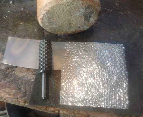
Making zinc foil rough for better contact with drum rasp.
If making stacks of electrodes as discrete units works
out,
then if I get back to trying to make cells for electric
transport, perhaps I could square off plastic plumbing tubes in the
oven, as I
had planned a couple of years ago. Tops of
flat plastic with slots for the electrode terminals could simply be
glued on, and again heat glue around the slots. The glass ball in a
smooth hole with a 3D printed retainer would still make a good filler
cap and pressure release.
A 7 or 8 cell, "12 volt" battery for my solar collector
system
would be a great start to test and measure performance over time.
July in Brief
Electric Mini - Tesla Model S
Someone came to buy a few bits of wood from me on the 3rd,
the day of the VEVA-Islands monthly meeting. He remarked on the long
extension cord coming out my upstairs window, which I said was charging
my electric Mazda from the solar panels. It turned out that he had
driven here in a Tesla and he gave me a ride. It was fabulous... and
terrifyingly powerful. When he stomped on the pedal, the car leapt
forwards and it was like going straight up, and we were doing 50 Km/h
or more in the space of 50 feet or so. all without squealing a tire.
But he had more... he had converted his wife's mini to
electric before buying the Tesla. I told him about the meeting and he
came in the Mini. It had lithium batteries in the back and a range of
something like 70 Km.
What a synchronicity to have met him that very morning!
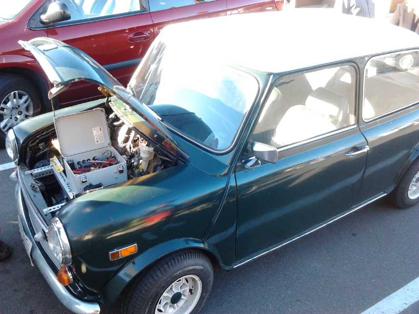
Electric converted Austin Mini
Electric
Mazda
After removing 1 battery of
11 from the Mazda RX7, hence dropping from 132 to 120 volts, the
currents seemed to go up enough to shorten the range appreciably,
probably, I thought,
owing as much to batteries having lower amp-hours as the amps rise, as
to the actual reduction in nameplate watt-hours - hence 'losing double'
with each
battery removed. On the 10th I bought two more 'reconditioned'
batteries (so 144v) hoping to 'gain double' and improve range
substantially, plus get more power with lower amps. Low voltages and
higher amps aren't wrong in principle, but they're wrong for this car
as converted, since it's not possible to fit two batteries in parallel
for each position, which would go from at least 8 batteries to 16, or
to
fit larger, higher current batteries of any common configuration. I put
one of them in immediately, but the other was still sitting around at
month's end. It turned out I had another battery problem than just one
less.
On the evening of the 18th I noticed that the voltage was
too low - by about 8 volts - for what should have been a fully charged
car. On checking, I found a problem with a charger to one of the NiMH
batteries, which was down to about 6 volts. That's battery damage
range, and it probably hadn't been charged for two trips or more.
It also turned out that this 6-pipe NiMH battery was "losing"
pipes by bad connections and so was responsible for much of the "losing
double". It was the very low voltage that had caused the charger
trouble - the solder holding the wire to the (very hot) current
limiting resistor melted. Here
once again is a problem that would have been caught in good time by the
individual battery monitor, which would have been beeping "red alert"
long since. I really need to get that going before I start losing my
pricey
NiMH batteries!
I fixed the battery - it was the one with twelve 6v NiMH D
cell pipes - by
breaking the pipes open and remaking it in six 12v pipes. Chief
problem with these 6v pipes was that I had put in nickel-brass "U"
clips at one end of each to give some spring tension to hold the cells.
Nickel-brass isn't the best conductor
and the currents were high enough that these got hot and softened the
plastic around the terminal bolts, causing bad connections, more heat,
and melted plastic. There were also cells, randomly distributed through
the tubes, that had solder on them from previous soldered battery
packs. As I had found, the solder becomes corroded and also makes for
bad connections. I scraped it
all off.
MnMn: Best Battery Chemistry Ever! (short version)
"Slapped together" cell PP#3 with new negode containing 3%
zircon.
 Notwithstanding my plan to
do "outdoor" and "active" things over the summer, I did a bit more
battery making
work - and then fell into ongoing new chemistry battery testing and
designs. And by about the 20th I decided I had practical batteries at
least for solar applications... by modifying my expectations rather
than the chemistry. Then on the 31st I figured out the reason for the
nagging problem
of inconsistent results charging manganese to metal and its high self
discharge: it worked below about 17°c - but not at 23°. The
MnMn
battery
worked great in a fridge!
Notwithstanding my plan to
do "outdoor" and "active" things over the summer, I did a bit more
battery making
work - and then fell into ongoing new chemistry battery testing and
designs. And by about the 20th I decided I had practical batteries at
least for solar applications... by modifying my expectations rather
than the chemistry. Then on the 31st I figured out the reason for the
nagging problem
of inconsistent results charging manganese to metal and its high self
discharge: it worked below about 17°c - but not at 23°. The
MnMn
battery
worked great in a fridge!
Cooled batteries might have been practical enough for
solar use, but at the last moment came a major chemistry breakthrough.
On August 2nd I decided to try one more thing, that might be very
significant, before sending this newsletter. I made an otherwise
identical electrode with 3% zirconium silicate in it to try to raise
the hydrogen overvoltage to a workable level, and slapped a cell
together. At 29°c it charged readily to 2.5 volts and appeared it
would continue to charge and to hold a high voltage charge in the time
I had to test it before sending the newsletter. The results will
doubtless be replicable. I think I've finally completed the chemistry
side of what I set out to do in 2008 and made a fantastic high voltage,
very high energy density aqueous battery, far beyond what anyone else
has done.
If the story following isn't a coherent as it might be,
it's because of the vital late breaking developments.
Tired of battery cases that somehow always seem to leak, I
found a large plastic jar, filled it half way with electrolyte, and put
cell PP#6 inside it. The jar wouldn't leak. I made a hole in the center
of the lid and brought the wires out through that. A jar makes a simple
case for stationary cells where size and weight are of little
consequence.
Instead of shutting off at a cutoff voltage that seemed
reasonable for a 2 volt cell, I ran a discharge test for a whole day on
the 24th (& 25th). The battery kept putting out current, at lower
and lower voltages, as perhaps only manganese is able to do as its
oxidation state drops a level at a time from valence 7 to 2. After 24
hours it was still putting out, but it had finally dropped below .9
volts and I shut it off. If one accepts voltage swings of 2
to 1 with much of the discharge available at lower voltages, it stores
a
fantastic amount of energy - far more than any single reaction
electrode such as nickel hydroxide. A DC to DC converter can take such
voltages
and put out a constant DC voltage to make a "voltage regulated
battery". And because the chelated Mn oxide substances never dissolve
or become a passive insulator in any state, it should be rechargeable
'forever'. And manganese is cheap.
When I ran the test, the manganese in the negative
electrode wouldn't hold a charge, so it was really
operating off the zinc 'conductivity additive', making the battery
Mn-Zn rather than
Mn-Mn. The breakthrough in thinking came first and remains valid; the
breakthrough in charging the negative to Mn metal particles came later.
50Ω discharge test of cell PP#6, starting just over 2 volts and hitting
.885 volts after 24 hours.
When the load was removed it recovered to 1.34 volts - probably Mn2O3
in the "+" side.
With the present low
current capacity the cells
seem
pretty hopeless for high current electric transport applications... but
for stationary, low rate solar PV use, poor performance can be overcome
by making cells with as much electrode substance as it takes to get the
desired power and storage capacity.
I visualize a horizontal stack of electrodes, current
collectors and separator sheets, with pieces of plastic at the ends to
sandwich them all together, wrapped up with cable ties, tape, or
whatever. The terminal extensions
of the collector sheets will stick up and protrude through slots in the
lid, separately or bunched up. Heat glue can seal the slots as now.
Materials and techniques for making these stacks is the focus as July
turns into
August. Coarse embroidery cloth (accordion folded?) may replace the 3D
printed vertical bar baskets to provide a gas vent between each pair of
electrodes.
For cell construction for stationary uses where an excess
of weight and volume
isn't a concern, my perennial case headache can be solved
simply by using glass or plastic jars filled with electrolyte. I found
some nice plastic "20 oz cosmetic jars" big enough to hold a cube stack
of
electrodes and lots of electrolyte. ABS I think - but as usual they
don't say. They have plastic lids that screw
on tightly. These can be slotted for the terminals to poke through.
Nothing attaches
to the body of the jar - visualize the jar turning to screw to a
stationary lid with everything attached to it.
A 7 or 8 cell, "12 volt" battery for my solar collector
system
would be a great start to test and measure performance over time.
The first MnMn in February/March 2012 worked and held
its charge. PP#3 in April 2013 worked, but had higher self discharge.
PP#6 in July wouldn't stay charged to Mn metallic. The difference
was... winter versus spring versus summer? On the night of the 30th I
put the battery in the fridge (8°c) and by morning, on the last day
of
July, I had the answer. The battery had at last, for the first time,
charged up to 2.45 volts and stayed over 2.2 with the charge removed.
Removed from the fridge, the voltages dropped, and put back in, the
charge voltage hit 2.5 volts by evening. It'll take some days of
charging at the present low rate to charge most of the Mn substance to
metal, and I'll probably increase the rate. It has to be higher than
the self discharge, which is doubtless still well above zero. Once it's
charged to metallic state, I look forward hopefully to much higher
conductivity.
A load test showed even lower drive at 8° than at room
temperature. Apparently fridge temperatures are cooler than needed to
hold charge - and too cool for good performance. Perhaps somewhere
around 15° might be 'optimum'. I suspect it's the plus side
objecting to the fridge temperature.
Temperature was, then, the key to my inconsistent results
charging the
negatives to Mn metal particles and keeping them charged. The Mn is so
energetic that it's borderline whether it charges and stays charged or
not, and a cool temperature of perhaps 15°c versus 23° makes
the whole
difference between success and failure. The cheap batteries with an
energy density higher than lithium work great in a cool place! I can
visualize making battery enclosures in the style of my shallow chest
Peltier module refrigerator, but cooled just enough for the manganese
to hold its charge.
Preferably, electrode additives will be found to bring the
operating temperature up into at least the mid 20s, and of course the
higher the better. Otherwise, the cooler idea is practical. It's
nothing like sodium batteries that have to be heated to an extreme
temperature to melt the electrolyte.
The project occupied more of July 2013 than I'd planned,
and I
didn't get very far on any other projects. On the other hand, after
5-1/2 years the Mn-Mn/moderately alkaline battery chemistry has been
found: the best, highest energy battery attainable. And its somewhat
obscure workings are at last basically
understood and the results are replicable. It's the end of the search
for a better battery chemistry. Progress on them can at last truly
proceed from the experimental research to the product development level.
Solar PV System: PbPb storage
Of course I wanted to hook some of my lead-acid batteries
to the
solar panel system, both to increase its storage capacity for now, and
to put the renewed batteries originally intended for the Mazda into
use, where their capacity might gradually increase with cycling. In
order
not to have a bunch of batteries with differing characteristics in
parallel and feeding into each other (especially mixing NiMH and PbPb),
I
decided to diode isolate each one in both directions. Since PbPb s
charge slowly, I decided to do it like the car, through small value
resistors from a constant voltage. The NiMH s and the main house supply
already have 14 volts on them when the sun is out. This goes to 5
diodes and resistors, one set for each lead-acid battery.
Coming the other way is a heatsink block with 5 heavy
current car alternator resistors. Each battery attaches to one diode
anode, and the block attaches to the common cathode side, which
supplies the main house power if it falls below the voltage of the
lead-acids less one diode forward drop (~.6v) at night or in clouds.
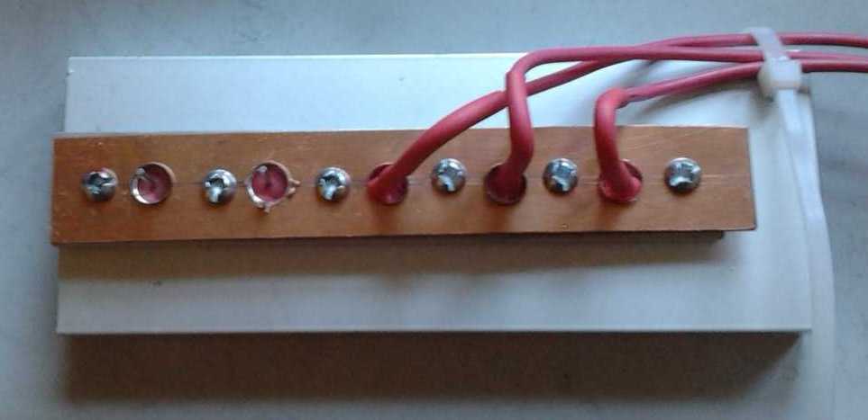
Okay, it just doesn't have that "professional" look to it.
(needs some sort of cupboard/shelf with roof.)
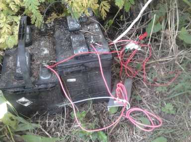
Then, it would seem from a
'battery renewal' discussion list that pulse charging is a requisite
for bringing 'renewed' batteries back up to maximum capacity. I decided
to make a pulse charger with a 24 volt transformer and a single
rectifier diode. Since one diode only rectifies 1/2 wave, the pulse is
under 50% duty cycle. I wasn't satisifed with that, and I attached a
computer control I made about 3 years ago when I was first doing
battery renewal, but didn't get much use out of then. I programmed it
to
turn on for short periods, so the strong 60Hz pulses are only going to
the battery 1/16th of the time every couple of seconds - another form
of pulsing. I set this up on the back patio where the batteries taken
from the Mazda were sitting, and started charging them. One that
wouldn't
charge up still wouldn't. I decided it should be shorted out again and
"reset" to zero, then I'd try the pulse charging again and see if that
resurected it. I'm pretty sure most batteries can in fact be brought
back to life and good capacity, little success tho I've had so far.
Pulse charging is probably the way to do it. Perhaps these will regain
their capacity and can go back into the car, or into the boat for the
electric outboard.
Evacuated tube with ammonia
I made an attempt to evacuate a tube with ammonia in it
instead of pure water, hoping for a lower boiling point. I still hadn't
bought the pipe fitting and copper end plug I'd been meaning to get for
the top end, and "made do" with another fitting with a galvanized plug.
At first it seemed successful. I wasn't sur eof the boiling point, but
by the next day the vacuum was gone - it leaked. The only other
accomplishment on this project was to finally make a special trip to
buy the fittings I kept forgetting to pick up.
Electric Hubcap Motor Pictures
Looking for one, I noticed that I'd never taken any decent
pictures of the latest (2012) model of Electric Hubcap motor, so here
are a couple. It is of course set up for mounting in the Chev Sprint
and driving the planetary gear torque converter.
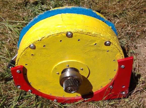
Rotor side
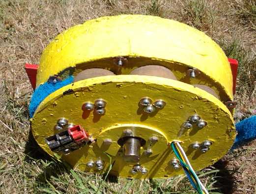
Coil side with air filter unwrapped showing ilmenite painted coils.
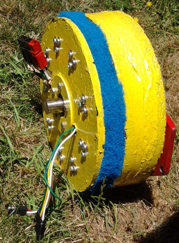
Profile view
In Passing
Incidental news, editorial comments & opinionated rants
Continued Collapse of the Financial
System
According to Max Keiser and others, a key indicator of the
coming crisis will be the rise of interest rates from near zero in
spite of anything the US "Fed" can do, with a consequent collapse of
the highly inflated "bond bubble". Another will be the collapse of the
"on-paper" bullion markets, comex and LBMA. The price of gold and
silver has been manipulated down to make the US dollar look stronger,
and those doing the manipulating must have expected people to dump
there precious metals as the price dropped. Instead there has been
unprecidented demand, and the physical supply held by the manipulating
banks must be about exhausted.
The sequences appear to be proceeding apace,
with bond selloffs recently accelerating at dropping values. (Okay,
Detroit municipal bonds were probably not the best investment, but
there'll be much more to come!) Some are talking about complete
financial system collapse and wiping out of all debts as well as
financial assets this autumn. Like the most dire predictions for
'Earth's population 12 billion by the year 2000' (IIRC) and now one for
something like '95% of Americans dead within next few years', it's
probably premature and exaggerated. It's also probably got enough truth
to it to be worth noting. And the world as a whole is overpopulated and
everything is highly dependent on everything else. There'll surely be
serious trouble in any lasting interruption of the
flow of goods and services. Everyone would be wise to have a good stock
of durable foods and perhaps access to food production - gardens,
chickens, fishing equipment... and savings and assets outside of the
banks.
And of course we should all try to contribute to social sustainability
in whatever ways we personally find that seem harmonious and useful. It
seems to me there are too many who only want to take from 'the system'
whatever it'll give them. This results from their own unfortunate
decisions and tendencies, but such are fed by a system that no longer
appears to
care about ensuring practical and reasonably fair opportunity for
individuals and families to better their circumstances and live a
decent life. The gross inequality and rampant corruption, the uncaring
about the populace by those in charge, breeds a populace of uncaring
individuals. This is the fatal, self perpetuating trend.
Today 'the system' is hostile to change,
but it will become open to it in the increasingly chaotic period soon
to come and indeed already underway in various ways in various part of
the world. The economical and social system needs
to be reframed in sustainable ways, and that needs a lot of creative
thought, caring, by a lot of people.
US War On Journalism update
From "dumbing down" the main news channels, to harassment
and threatening of Americans reporting or putting on websites news or
views contrary to propaganda or exposing crimes 'the establishment'
wants kept quiet, to gunning down Reuters journalists from a helicopter
in Baghdad, to arresting people videoing police actions, it is
increasingly apparent that an energetic war is being waged against
journalists and freedom of the press by the US government. They're
still trying to get revenge on Julian Assange and Ed Snowden. (After
the
rampant US espionage program revealed by Ed Snowden, charging him with
"espionage" is ironic.)
This month the war took another savage turn with the booby
trapping of the car of 'mainstream' journalist Michael Hastings,
apparently by government employees. Hastings had done a candid
interview with a top US general in Afghanistan that was printed in
Rolling Stone. The general said some things about "we're losing" that
he evidently hoped would lead to the US sending more troops there, but
instead he ended up being sacked.
In the days before he was killed, Hastings told those
around him that he was about to release a big exposé on the CIA.
A few hours before his death, he e-mailed to Wikileaks that he thought
the FBI was 'investigating' him. It would seem that they or whoever
were actually busy booby trapping his car. As best I understand it the
car suddenly accelerated wildly, caught fire, and then,
already burning, hit a tree at high speed. This was deemed
"an accident" by the police. They must have been hard pressed to ignore
witness testimony and look the other way, when the engine was blown
something like 300 feet into the air and landed 75 feet away. People
who knew Hastings well said he was an exceptionally careful driver.
The story was reported on The Corbett Report,
"Crashes of Convenience". James Corbett is an American who does his
news reports on Youtube from Japan. He's not alone among American
journalists living and working abroad, where they doubtless hope to
avoid meeting some sort of fate akin to Hastings'.
In the west it used to just be unsuspecting inventors who
were at such risk, being quietly removed from the scene of action by
murder or somewhat more subtle underhanded techniques by corrupt
corporate interests - not by the government. Welcome to the club,
journalists! Before the internet, such criminal tactics used to work
and usually no one was the wiser. They can't be hidden any more, and
the backlash against such crimes works to destabilize the whole of
society. If they continue, martyrs like Michael Hastings will be
definite factors in inciting whole populaces to rise up to overthrow
their 'governments'.
Here's a couple of samples of things this month you
probably won't see in the American mainstream news:
* Former US president Jimmy Carter said the USA has no functioning
democracy today.
* There's a book out about how the US has become the USSR. (I don't
recall the title - something like "role reversal".)
To find the real journalists and news, try youtube,
RT[.com], Aljazeera, news & magazine websites, etc.

There it is! There's the planet where all the trouble's coming from!
No, not the big one with the rings... the teensy little blob to the
lower right:
"Earth", 1.6 terrameters from the Cassini's camera. We are all on it.
Electric
Hubcap Motor Systems - Electric Transport
Blown motor controller fixed - Realizations: To see 120 amps, Max
amps would be ~= 360?
The controller worked again after replacing just two power
MOSFETs. I tried all the "?" IR2133s from previous controller blowings.
To my surprise only one of them, the first one, was good out of five.
But at least, running the controller off the lab power supply with the
supply current limited to under 10 amps, I didn't blow anything more
with testing. (One of the chips tried its best to blow everything. Two
had a phase drive
missing, and the last seemed to do nothing at all.)
Now... any chance I could just get back to the Sprint car?
No, I decided to look at the other controller while I was at it. Then I
didn't even get to that.
But I also started to consider that at low RPMs or stopped
with no back EMF,
the peak current to the coils must ramp up to a level much
higher than
the
average DC current from the battery. Perhaps 3 times as high. In
that
case, seeing the "rated" 127 amps from the battery on the meter would
actually mean about 380 amps peak to
each set of coils. Here I've been thinking I'm limiting them to 1/2
the MOSFETs' rated continuous current, when in fact to see such a
current on the meter, it would be 1.5x! So if the current cut-out is
set to my normal 127 amps max, the most the meter may show is around
40-45 amps with the motor stopped or at very low RPM. So apparently I
shouldn't be wondering why I see maximum current readings much lower
than the current trip-out setting. Obvious after realizing it, of
course!
Furthermore, the amps ramp
up more and more slowly as the
motor RPM increases. If the max has been set to 380 amps, that may read
as 127 amps DC with a stalled motor, but at some
point of RPM and load, they could ramp up to 350 amps and never hit
380, so the
average current would be very high, and the controller would probably
blow.
These realizations give me
better appreciation of what the MOSFETs in the controllers are
contending with, and why it doesn't seem to take a lot to blow them -
actually it does, but they're getting a lot more than it looks
like on
the DC ampmeter.
Chev Sprint
At the risk of having insufficient power to move the car
instead
of just enough, I took one of the batteries out and just had 24 volts.
I really didn't relish the chance of blowing the motor controller
again, and they seem more reliable at 24 volts. Of course, it shouldn't
take a lot of
power to move the car if everything is working the way it's supposed to.
Next a means was needed to keep the flat belt from sliding off the
pulleys sideways when it's slipping. (When it's not slipping it tracks
well enough.) I supposed raised sides on the pulleys would be best and
simplest, and
I took off the top pulley in order to glue plastic sides onto it. Then
somehow the month slid by without getting anything more done.
Pitot Tube
Speedometer for low-speed Boats
When I was doing the Electric Caik Outboard in February, I
was looking for an economical water speed indicator. (TENews#61) The
pitot tube seemed ideal, but all the speedometers that connected to
pitot tubes went up to very high speeds and didn't even read below 10
or 15 MPH. That's pretty useless for most boats besides high-speed
planing hull
speedboats.
I found a table that showed the height that the pitot tube
would raise water to at various speeds, and it varied with the square
of the speed. At one MPH it's just a centimeter, but 4.3cm at 2 MPH
(table in TENews61 has this figure wrong), and at 15 knots it'll
overflow an open ended tube sticking 1 meter above the water line.
It occurred to me later that a closed ended tube would be
much better, giving a more linear calibration and extending the range,
since air pressure in the tube would counter the pitot pressure as the
water rises higher in the tube. This should also help stabilize the
readings somewhat in waves and turbulence. It would still bounce around
a bit no doubt, but the boater should get some quite decent indication
of speed between about 2 or 3 and 15 or 20 MPH. The low end speed is
dictated by the accuracy and precision of readings on a moving boat in
waves. For example, (for an open tube) if the water column wavers up
and down 4cm, that's the whole height of the reading for 2 MPH. But
only 1/4 of the reading for 4 MPH.
Of course, figuring out the calibration would involve a
bit of math with the rising pitot pressure causing rising air pressure.
I looked on the web for one that has already been done, but found
nothing. I find it hard to believe no one would have done it for
displacement hull boats, or indeed that no one makes such closed end
tubes ready to use for that purpose. But I haven't found anything. All
it needs is a clear tube with a plug in one end and speed markings -
just about like a thermometer.
In lieu of that, I really ought to make an open ended one
before my next boat excursion. Open ended does have the advantage that
the calibration is available in standard tables.
To keep the "zero" mark at the
waterline, I'd have the whole thing outside the boat on a float. And at
that point,
maybe it could be a lightweight unit that's towed on a light line. That
way it would also be out of the way when launching and landing. It
might
be a bit hard to read at a distance... then again, maybe there
could be a small colored float inside the measurement tube to help with
that.
Then I thought that better than towing with a rope would
be hinged arms, upper and lower, holding the unit to the transom/stern.
It would be free to float up and down to stay at the waterline, but the
tube would be held vertical and couldn't tip, and it would be close to
the stern for reading.
Electric Equipment Projects
Summer
Thermoelectric Fridge Notes
I thought that in the
summer the longer sunny hours would mean the fridge could run almost
purely on solar power. Instead, with warm summer weather, it could run
24 hours and not get even the coldest area below the ice tray down to
5°c. Mostly it was 5.5 to 6.5°. There was no point worrying
about the control when it was best if it should never shut off.
On the 10th I bought another piece of 1" extruded styrene insulation.
I cut it in half and put one piece under the fridge and simply set the
other on top of the lid. It made a difference. Temperatures dropped to
5° in the day and 4° or lower at night. When I finally tried
turning it off overnight, there was more ice and a lower temperature
than usual in the morning.
This trend reversed itself when I put both extra sheets
underneath (giving 5" of foam on the bottom) and at the same time took
out or moved some of the food, making more open air flow from the
cooling unit to the
other side of the fridge. I verified it was the air flow by stacking up
some cans to block it, and the temperature near the ice tray went down
below 5 again. Of course, the warmer side of the fridge away from the
ice tray is obviously cooler with better air flow.
I also found that with the warmer weather the fridge would
get up to 7 or 8 degrees near the ice tray when it was turned off
overnight, even with a little ice still floating in the tray.
At this point I'm considering the thermoelectric fridge
idea to be marginal in practicality. I'd recommend using at least 4" of
extruded styrofoam insulation on the top, bottom, back and sides. (If
the front is thinner, 3",
you don't have to reach in as far.) Obviously even more insulation,
and fridge shapes such as the octagon and or the stepped floor to
reduce external surface area per inside volume, would be beneficial.
I've gone to 5" in the floor, which is the coldest surface, and where
thickness makes no difference to space occupied except that underneath,
which isn't very useful space.
I've been running with the 8-volt and 15-volt, 8.5 amp Cui
Peltier modules in series on the 12 volt supply, using perhaps 45-50
watts. I haven't yet tried hooking up the two 15-volt modules in series
(35-40 watts) to see if they'd perform as well or better. (There may
have been a piece of grit preventing good thermal contact when I tried
it before.)
I evacuated a pipe with ammonia-water to make a radiator
that
would start to boil at room temperature to replace the warm side
heatsink and fan, but it seemed to leak - it quit working by the next
day. I got better pipe fittings for the next try, but didn't get to it.
It's possible that an evacuated pipe radiator for warm
side heat dispersal will make the somewhat marginal performance of such
fridges more acceptable.
Electricity (Energy) Production
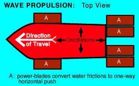
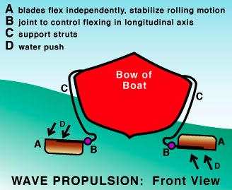
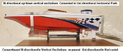
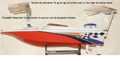
Wave Power for Boat Propulsion
I've had the idea that one could use wave power on a boat
to make electricity. Of course, one could then use the electricity to
propel the boat. Here's another idea I've run across: Francois Kneider
skips the 'middleman' and has the waves propel the boat directly.
http://www.rexresearch.com/kneiderwave/kneider.htm
The waves move "power blades", up and down, and these act
as fins to push the boat. (Considering how small oars or paddles are
compared to the blades in these diagrams, I suspect that smaller blades
might work better. But that may depend on wave size.)
However, wave power on a boat making electricity can
charge
a battery even while at anchor, and the electricity can then be used at
a
future time to provide any desired velocity with a regular electric
inboard or outboard motor.
Electricity Storage - Turquoise Battery Project (etc.)
Production Prototype Cell #6 ("PP6")
I started this and made the posode in June. A new feature
is a piece of carbon fiber cloth across the front and wrapped around
one edge behind the graphite current collector sheet. This is intended
to increase the overall conductivity of the electrode by connecting
everything across the front face, in addition to the current collector
connection across the rear face.
Negode
I mixed some materials for the negode. It was pretty
similar to cell PP3 (TENews62) except I used a lot more granular
manganese. I added a little VeeGum, Sunlight dishsoap, and water to the
42.5g portion I compacted. The electrode was a bit short. (45g
next time was slightly long.)
50g Granular Mn
50g fine (<300) Mn powder
50g Mn oxides powder (MnO2, Mn2O3...)
22g Zn flakes
22g Zn fine powder
2g Sb2S3
---
196g (Hey, that was supposed to be 200!)
When I was mixing it I noticed a lot of fine fibers in the
mix. Either something I bought was contaminated with something or I had
put carbon fiber in with some manganese oxide I used. Under a
magnifying
glass it looked to me like carbon/graphite fibers, all single fine
strands of a uniform thickness. Ouch! There isn't supposed to be any
graphite in the negode - it might bubble hydrogen. It would be good in
a plus side, except I'd mixed in the zinc and stibnite for a minus. I
decided to try it anyway, having mixed 200g of substance.
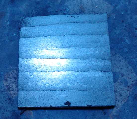
I dried it on
porous brick and torched it only about 4 seconds instead of double
that, with a small propane torch. Next I decided to match the other
side and put a perforated zinc foil current collector sheet behind the
separator sheets.
Yikes! - at no time did I think to check the conductivity
of the briquette, and I assembled the cell without having done so.
Considering that poor conductivity is probably the chief problem,
that's
a poor step to miss! Nor did I take pictures of the perforated zinc
sheet arrangement.
The cell didn't charge as expected. Instead
of 2.6 volts, it charged up to about 2.0 or 2.1. Well, what was
different from PP#3? Two fundamental things - maybe three. First, I put
some ferric
chloride onto the posode briquette, and since it didn't quickly soak
in, I brushed it around over the entire surface. Second were those
graphite/carbon fibers in the negode. Thirdly I just might have put a
layer of calcium hydroxide at the posode current collector in #3. I
didn't think of it this time. (Methodical I'm not!)
At first I was suspicious of the first item, but then I
thought
that the cell was charging up to the voltage one might expect from
permanganate-zinc. Continued charging after that made a lot of tiny
bubbles and
loss of electrolyte. It could make sense that the abundant carbon
fibers were bubbling hydrogen throughout the negode before it was up to
the charge voltage of metallic Mn, so the Mn would neither charge nor
stay charged.
This points to the probable need for quite pure
ingredients in the negodes to prevent self-discharge. Any little
metallic- or conductive carbon-based bits of 'stuff' could gradually
bubble hydrogen and steal away the charge. In fact, I think I won't
worry about self discharge until I'm sure I have all "lab grade"
materials in a negode.
Either that, or some way of 'masking' any offending grains
of powder is needed. Here once again borax in the electrolyte might be
useful to form borohydride and hopefully neutralize such sites. (As for
neutralizing a whole mesh of carbon fiber, I have my doubts.)
Since 20% of the electrode was zinc
powder for conductivity, and the current collector sheets were also
zinc, it would function quite well as a Mn-Zn cell. It didn't have much
current drive, but driving a 50 ohm load, it hung around 1.5 volts (so
driving 30mA) for over 13 hours, showing at least .4 AH of capacity. A
stable drive voltage and useful if not high capacity
definitely made it a real battery. At that point the voltage was
starting to fade and had dropped to 1.41. It may well have had quite a
while yet, but I shut it off since I'd be asleep. That
it was probably KMnO4-Zn and not MnO2-Zn was only
indicated by the fact that if the load was disconnected the voltage
headed quickly for 1.8 volts and beyond - at least for the first few
hours. Doubtless the carbon fibers, as well as the two zinc
current collector sheets, contributed much towards getting a lot of the
zinc properly connected to the terminal in spite of the bulk of Mn(OH)2
that (possibly) couldn't charge, or stay charged, to Mn metal
particles.
With only 20% of the negode being the effective
active substance, perhaps it's not very surprising that the current
drive was pretty low. On the other hand, the current collector sheets
themselves were zinc. They should at least be very, very low electrical
resistance. That points to the posode as the main problem - or the
electrolyte. KCl is much less soluble than KOH and the electrolyte's
specific gravity can only be raised to about 1.12 instead of 1.25 or
1.3. But should that make a 30 or 50 times conductivity difference?
It's perplexing to have seemingly good cells that suffer significant
voltage drop with less than 1mA/sq.cm of current flowing, where perhaps
20 to 50mA/sq.cm would be expected figures for maximum usable loads...
or surely at least 10. But then I have had 10 or 20 with some of my
cells. Later with a 10 ohm load, voltage settled around just 1.2 volts:
120mA and 3ma/Sq.cm. (Opening the battery later revealed that less than
1/2 the back of the negode was in contact with the current collector.)
With good current, I'd be happy with Mn-Zn except for
zinc's well known
characteristic of gradually migrating and losing capacity with cycling,
and in so
doing sometimes forming dendrite bridges that short out the cell across
the electrodes.
These make for short cycle life. There
are many patents for ways to
make zinc work better, but none seem entirely effective. (One company
does make Ni-Zn AA cells, which are rated at 1.6 volts.) This is
possible in my cells because of the zinc current collector sheet and
zinc powder electrode additive, but it's probably not enough zinc to
cause problems, and the zinc current collector looked pretty good when
I opened the cell.
I decided the first thing to try would be to add some
borax to the electrolyte and see if it helped the cell charge more
towards the voltage of cell PP#3. If there was any notable improvement
it
would support the borax/borohydride 'impurity masking' idea.
That didn't seem to work. Then the conductivity of the
cell dropped remarkably. However, it did seem to be holding voltage
pretty well when left off of charge for 32+ hours. On the 10th I opened
it, expecting to see a badly corroded zinc current collector sheet. But
it looked good. It looked like it wasn't making a good connection to
the electrode, and on reassembling it with some more rubber backing
behind it to push it against the electrode, it worked much better.
However, it was leaking badly, and the zinc sheet probably still wasn't
touching the electrode briquette over more than 1/2 the surface. It
would seem that mechanical things are still the lion's share of the
problems, rather than chemical things.
Second Negode
Since the borax didn't seem to make some miraculous
improvement, I decided to
make a new mix, virtually identical but without the carbon
fibers, and replace the negode. The two
small jars of Mn oxides, one of which must have had the
carbon fibers mixed in, were empty, so it wouldn't happen again. (I
remind myself to carefully label my containers, but it doesn't
always happen.)
50g Granular Mn
50g fine (<#300) Mn powder
52g Mn oxides powder (MnO2, Mn2O3...)
20g Zn flakes
20g Zn fine powder
3g Sb2S3
---
195g (well, each electrode takes a bit less than 50g anyway)
 Theoretically
(ahem - *theoretically*) the 45g electrode
has over 25 amp-hours of manganese. I wouldn't expect to actually get
half of that. The granular Mn has low surface area with most of the
metal locked inside, and the rest won't be perfect either. It'd be
great if it's 10 amp-hours, but that's probably still a pipe dream -
and more than the
positive side has.
Theoretically
(ahem - *theoretically*) the 45g electrode
has over 25 amp-hours of manganese. I wouldn't expect to actually get
half of that. The granular Mn has low surface area with most of the
metal locked inside, and the rest won't be perfect either. It'd be
great if it's 10 amp-hours, but that's probably still a pipe dream -
and more than the
positive side has.
This time forgot to add Vee-gum but I remembered to check
the surface resistance at
a few points. Before torching it was from several K ohms to several
tens of K ohms, notwithstanding being perhaps the toughest briquette
I've made (so forget the Vee-gum). Afterwards it was tens of megohms,
either side up - oops, overdid it again!
That would doubtless explain poor current capacity right there. ...But
even with
all that zinc powder, zinc flakes, and both fine and granular metallic
manganese?
I don't even like the kilohms figures, much less megohms.
Maybe I should try lead or bismuth, or powders thereof, in place of
zinc after all? Permanganate-manganese is a cell
that'll keep going and going like the reputed Eveready battery bunny,
at ever lower voltages, until all the zinc is oxide and all the
manganese in both electrodes is in the same state.
I can of course hope that the manganese oxides start
charging to Mn metal or that things become more conductive with use on
the microscopic level, and the whole thing will become more conductive
with charging, cycling or just time. Cell PP#3 showed just such
ongoing, but gradual, improvement until it quit.
As was probably the case with the carbon fiber, many or
most impurities would
bubble
hydrogen at the
high reaction voltage of Mn metal to Mn hydroxide. High purity Mn and
Mn oxides would seem to be required, perhaps
eliminating pottery supply MnO2, and it has to be graphite-free, so
salvaging it from dry cells is also out. If this surmise is correct,
I've had the chemistry right since the end of February 2012 and really
just need purer ingredients.
Or perhaps the borax, forming borohydride where the
hydrogen bubbles are, might gradually 'glaze over' the impurities and
passivate them.
But after a day, the cell with the new electrode again
refused
to rise over about 2.24 volts (eventually reaching 2.33 volts a day or
two later) with a
27mA charge running. It sat there
hour after hour. It stayed higher and higher when the charge was
removed, eventually approaching 2.2 volts, but the on-charge voltage
didn't rise much. There was no more carbon in the negode, but the
voltage
was similar with or without it.
So where did that fabulous 2.6 volts, and 2.4 volts under
load, of
PP#3
go? Admittedly it was a higher voltage than expected from MnMn. I
finally decided I must have put calcium hydroxide into the
PP#3 posode, as a layer painted onto the current collector, and that
the
extra voltage must have been attributable to the Ca(OH)2 (or "CaO:H2O")
charging to CaO2 -- a reaction of +1.55 volts I had once considered
might make a great high voltage posode. I then decided that it was such
a high voltage it was bound to self discharge, releasing OH- ions.
(CaO2 + 2 H2O => Ca(OH)2 + 2 OH-) But I decided to paint it onto the
positive collector plate as something to inhibit oxygen gas generation
during charging. That would seem to explain many things:
* the cell voltage (2.6v) was higher than I had expected (2.2v) because
of the calcium charging up to dioxide.
* the discharge curves matched the actual case: discharge began around
2.4 volts - the
CaO2 voltage plus the Mn negode - but fairly rapidly dropped to about 2
volts - about where cell PP#6 is. It seemed like 'disappointing
performance' at the time, but it would be inevitable because there
wasn't very much
calcium. There's lots of amp-hours of permanganate for extended
discharge times once
the voltage is below 2.1 or so.
* the overnight self-discharge was high for the very reason I hadn't
chosen calcium as the main ingredient: high self discharge was expected
from calcium dioxide.

PP#6 doesn't charge to such a high voltage because I
didn't paint any Ca(OH)2 onto the positive current collector in it.
(Methodical and consistent I'm not.) Instead it starts to bubble gasses
when the charge voltage gets up to
around 2.33 volts. So all along I've had working MnMn chemistry, making
a cell that might be rated (pretty optimistically) as 2 volts under
load. If
it's charging up above 2.35 volts or so, it's already 'full' and is now
charging up the calcium dioxide anti-gassing additive (if present),
which may be expected to self
discharge itself in a few hours, leaving about 2.2 open circuit volts.
If the temperature is down around freezing, calcium
dioxide may hold its charge a long time.
In fact, the hours it takes to discharge may point to
potential for research into ways to raise the oxygen overvoltage so it
can
hold charge reliably, for a higher voltage electrode needing only 5
cells to make a 12 volt battery. Like the potassium
permanganate, Ca(OH)2 is slightly soluble, but this should be
controllable by the same chelation technique.
However, the MnMn with calcium hydroxide ('slaked lime')
as a
gassing inhibitor and alkalizer seems very nice - even "elegant" as
computer programmers used to say - and I'm going with it.
In all this thinking about voltage, I hardly noted that in
one 50 ohm load test on the third day (7th), the cell gave amazing
performance. It ran 13 hours before I shut it off, heading for 400mAH.
It dropped to just over 1.4 volts after an hour, then went back up to
hit 1.5 from hour 7 to 10, then went down again to a bit over 1.4 by
hour 13. The only reason I shut it off then was that it was 3 AM. But
in subsequent tests - 10 ohms - it didn't seem to work very well, and I
wanted to try without the carbon fibers and see if it had less self
discharge.
Discounting that one test, the second negode performed
much better than the first
one. Notwithstanding the high resistance readings, it delivered the
same milliamps at substantially higher voltages in load tests. It could
drive a 10 ohm load at 1.3 volts for 18 minutes instead of at 1.0 volts
for 3 minutes. Since the chemicals were the same except for eliminating
the fine carbon fibers, that doesn't say much for the efficacy of those
fibers in improving conductivity. (Could the Vee-gum have reduced
performance? There was only 1% of it. But the second electrode seemed
just as tough as the first, so there seems no reason to add it anyway.)
Notwithstanding the better electrode, in a test with a 50
ohm load the voltage dropped to 1.73 volts after 20 minutes, while in a
10 ohm load test it dropped to 1.28 volts in the same period (and 1.25v
after 25 minutes). There's no doubt that these tests could have been
run much longer and would have disclosed at least a few hundred
milliamp-hours of capacity, but I was saving long tests for later.
After the 25 minute, 10 ohm load test, delivering an
average of about 1.34 volts (& hence 134mA), it took 4 hours of
charging at about 23mA to bring the charge voltage back to the same
point, 1.323 volts. 25 minutes at 134mA is 56mAH of discharge. 4 hours
of 23mA is 92mAH of charge - 1.65 times as much. It's not high charge
efficiency, but it's not completely disproportionate either. Of course,
136mA is a pretty hefty (hence inefficient) discharge rate for this
little cell. A low rate discharge would probably show better charging
efficiency and is something to monitor following the next lower current
load test.
In a 20 ohm load test on the 18th, the cell was well below
1.5 volts for most of the test, ending after an hour at 1.2 volts.
On the 19th I ran a long 50 ohm load test, starting from
about 2 volts and finally dropping below 1.1 volts after 370 minutes
(6 hrs 10min). At least it was over a volt throughout.
Total electrons moved was about 150mA-hours. It recovered to about 1.55
volts, which may well have mostly been MnO2 + Zn. I'm pretty sure it
would have performed better if it hadn't been leaking. When charging
was resumed, it shot almost instantly above 1.8 volts. It took about 9
or 10 hours (past my bed time) to charge up to its previous charging
voltage. As it was charging more slowly than it had discharged for the
first three hours, the charging efficiency must have been pretty decent.
On the 21st I ran a second 20 ohm test, with the cell
having been well charged the previous day and overnight. At first it
seemed to perform much better than the first time. It started at 2.3v
no load, and was hundreds of millivolts higher than on the first 20 ohm
test for the first few minutes. But by 15 minutes the advantage had
dropped under 100mA (and the voltage to 1.5v), to 50mV after 25, and
went lower after 45. That meant it was discharging the same(?) amount
of substance faster into the same resistance - ie, with better
conductivity. If I could make cells that would last and not leak, they
might start performing quite well by 10 or 20 cycles. Hopefully the
substance utilization is also increasing.
On the 24th I tried to glue a plastic face onto the cell,
but it leaked. After several attempts to stop the leaks (there was just
a small one left... somewhere), I gave up and found a plastic jar that
would hold the whole cell. I put it inside and filled the whole jar to
the appropriate level with KCl electrolyte, drilled a hole in the
center of the lid, put the test leeds through the hole and connected
them, and screwed the lid on. (mostly of the way - the terminals stuck
out just a bit.)
Then after charging a just few hours I tried a 50 ohm load
test, which I ended up running for exactly 24 hours at ever lower
voltages, starting just over 2, dropping to 1.6 within and hour, and
then running for ages from 1.5 volts gradually down to .889 at the 1
day mark. I calculated it put out 551.5 milliamp-hours. By that time
the voltage was dropping very, very slowly, and it obviously would have
put out more at still lower voltages - maybe even another day or more.
Some time I'll have to try really running it down, like to 1/2
a volt or so. I'll bet it has a couple of amp-hours in it.
It recovered
quickly to almost 1.3 volts, and to 1.35 volts over about 3 hours.
It'll take over a day of charging at 22mA (with the usual 50 ohms) to
recover to over 2.3 volts, even with efficient charging.
After the test and
some time for recovery, internal voltages were: +.664 & -1.138 WRT
a graphite electrode, total 1.802v. (The meter read 1.799v) However, it
turned out the graphite electrode seemed to be around +.3 volts, not
zero. I started using a zinc electrode. It showed the the negative
voltage was about the same as zinc, -1 or so, so the positive was
higher, maybe .8 or so. I sense that I should have a reference
electrode with some known voltage to measure from.
Different Circuit Designs for a Different Battery?
Most batteries put out a relatively steady voltage, which
rapidly drops off to nothing when their charge is exhausted. But as
I've said, MnMn really has no reason to suddenly run out of charge and
die. Instead it can continue putting out current at ever lower voltages
as the oxidation levels of the Mn change, until both electrodes are in
the same oxidation state, somewhere between 7 (permanganate) and 0
(metallic).
In the above test, 6 cells in series would have gradually
gone from
being a 12 volt battery to a 6 volt one, no doubt with potential for
running as
long again down to 4 volts. The variable voltage can be seen as being
an interesting circuit design challenge instead of as a battery
chemistry problem. If the battery was fed straight to a
circuit, the voltage would either be too high at first, or too low as
the charge got lower. It could however be fed to circuits such as a DC
to DC converter or an EV motor and controller, which can accept a wide
range of input voltage. The EV will get gradually less energetic. The
converter will continue to put out a constant output voltage to supply
loads. In the Mazda RX7 as an example EV, the motor and controller can
accept a considerable range -- about 65 volts to 160 or more. (It's
crawling at 65 volts.) The Zahn DC to DC converter will accept 18 to 44
volts input and put out an exact (adjustable) voltage in the range of
14 volts.
But the varying input voltage challenge from a battery
whose voltage can vary by more than 2 to 1 is almost trivial compared
to the idea of using "supercapacitors" for energy storage, where the
voltage output from the capacitor could range from thousands of volts
down to almost zero.
One can always charge the battery only to a certain
voltage if that's the desired maximum, eg, staying below 1.8 volts or
so and forming MnO2 but not permanganate in the posode, and one can
always discharge only to a given desired minimum voltage. And probably
I can get the higher voltages to last for longer periods with
improved constructions -- or even just with cycling. PP#3 held higher
voltages much longer than PP#6, perhaps because of the calcium
hydroxide.
Pos.React.
|
Valence
|
Neg.React.
(Valence 0 -> 2)
|
Cell
Voltage
|
MnO4-, NiOOH
|
7, 3 -> 4,2
|
Mn
|
2.2
|
MnO2
|
4 -> 3
|
Mn
|
1.7
|
Mn2O3
|
3 to 2.67
|
Mn
|
1.5
|
Mn3O4
|
2.67 to 2
|
Mn
|
1.2
|
Ni(OH)2
|
2 to 0
|
Mn
|
.8
|
Mn3O4
|
2.67 to 2
|
Zn (if Mn neg.
is depleted)
|
.8
|
Lingering chemie questions include:
(a) whether graphite in the negode causes self discharge. I think to
answer this, I may make a similar negode except use a carbon fiber
front sheet, a flexible graphite current collector, and graphite powder
additive, all in place of the zinc sheets and powder. That should
provide a pretty definitive answer. If the zinc can be eliminated so
can the possibility that the battery can be discharged low enough to
start oxidizing (discharging) the zinc metal, which may well reduce the
otherwise "indefinite" cycle life. With graphite, I think the cell
could be discharged even to zero theoretically without damage. On the
other hand, zinc is probably more conductive.
(b) Is any remaining self discharge due to impurities in the chemicals?
If so, can borax passivate the culprit bits, or if not, does buying
high purity stuff from a chemical supplier solve the problem?
(c) Of what significance is pH? In this cell it has been sitting around
7 to 10 (making me very nervous), yet it still seems to work okay. If I
put in the calcium hydroxide layer in each cell, it would probably go
up to 12 or 13. Or a little potassium hydroxide added to the
electrolyte would of course bring it rapidly up to any desired value
short of 14. Keeping it at some 'optimum' value over time might be a
bit trickier. or it might sit stable just fine at any alkalinity it's
mixed to.
(d) Could a calcium peroxide/hydroxide posode be made to work without
prohibitive self discharge? Maybe if it was kept cold in a fridge? The
possibility of getting 2.4 nominal volts per cell seems awfully
appealing!
Cases: wide mouth jars? Oven squared ABS Plumbing Pipes?
After that, the next step will be making batteries with
multiple electrodes in order to get higher current capacity and high
amp-hours. I'll need to get the 3D printer working to design fatter
cases to hold them. Instead of 70mm wide x 13mm thick x 100mm tall,
they might be 70 x 60 x 100, holding about 13 electrodes (5 '-', 6
'+'), and instead of 41sq.cm of interface area they'd have 492sq.cm,
changing 100mA into 1.2 amps and an amp-hour or two into 6 or 12.
This will make them useful, if not for transportation, at
least for solar energy storage, where the rates of charge and discharge
are low. If
more performance or capacity can be tweaked out of them, as seems
reasonable, so much the better.
I started thinking that if I can put the electrodes
together in interlocking, self stacking baskets, perhaps the present
'front load' cases should go back to being 'top load', which also
minimizes the consequences of leaks. After prototypes with the 3D
printer, I started to think of injection molded parts again: case
bodies, baskets, tops and filler cap covers. The glass marbles would be
retained to cover the filler holes.
Then I started thinking that if they were for stationary
solar use, and if the stacks of electrodes could be made into single
units, perhaps they could simply be immersed in wide mouth jars. A
plastic lid could be printed that the electrode terminals would stick
out through. This seems simple and has the least of printed
plastic parts (and hence the shortest printing times).
I was looking at "wide mouth mason jars", but searching my
recycling box I noticed an Adams peanut butter jar. Its mouth can
swallow the mason jar mouths, and my whole present size battery fits
right inside the jar. Apparently I've noticed the wide mouths before,
because I found two more in my battery lab cupboard. But it takes a lot
of peanut butter eating to liberate each jar!
On the 24th I found the above mentioned plastic jar, which
I recalled I bought at Industrial Plastics. I think it's ABS. That or
some similar just a bit smaller might just make the simplest cases of
all. I bought 3 more the same, and 2 a little shorter, the next day.
Next: how to put submersible electrode packages together.
Roughening current collectors for better contact
I've mentioned that ideally one would use grills with a
fine mesh. Nobody makes zinc or graphite grills. I thought of using a
hammer with points sticking out. Someone suggested a cylindrical rasp,
and I found one at Rona.
My plan now is to turn it slowly in the milling machine
and put a piece of greased wood as a backing behind it. The rasp will
pull the zinc sheet through the slot and indent the surface. This will
probably need to be repeated a couple of times since the rasp isn't as
wide as the electrodes.
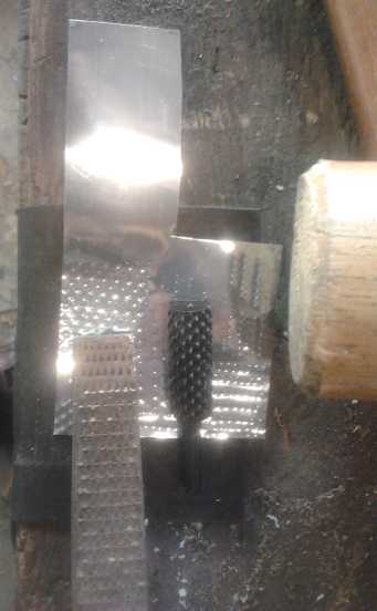
Hammering a zinc current collector to rough texture with a rasp, then a
cylindrical rasp.
Compacting tool: Hammer?
It occurred to me that a hammer might be at least as
effective an electrode compacting tool as a press - and probably
faster. The die inserted into the edge compactor (detailed a few issues
back) may best be one of hard tool steel to minimize mushrooming of the
top edge.
I tried this on the
19th. Different areas seemed to have wildly different surface
resistances. The best areas were much lower than I'd previously
attained with these
ingredients - below 1/2 a kilohm. (The meter used and the meter range
setting - and probably even the sharpness of the probe tips - also make
wild differences.) I expected the low current per electrode interface
area and the
active material utilization percentage would be greatly improved with
more
powerful compaction. However, measuring again later, the resistances
were in the megohms as seemed to be the usual case.
It may be that much
of the zinc, and
perhaps the manganese, in these electrodes gets converted to carbonate.
This would probably work to passivate the electrode.
If that's so, it may be possible to reverse that by adding a little
potassium hydroxide, or dipping the electrode in KOH, and then rinsing
it out. The carbonate will exchange and make potassium
into carbonate (soluble), and the zinc and manganese back into oxide or
hydroxide. Hmm... or does carbonate get removed when I torch it, anyway?
To attain best compaction,
I'll have to be sure I'm only adding and
compacting a little material at a time into the compactor slot -- and I
think I'll use a heavier hammer. To do it with a press I'd want a long,
strong lever arm and a base to match it, with good height adjustability.
Things to reduce self discharge
1. Changing the electrolyte, especially from the initial fill, often
helps quite a bit. Certain solubles in the electrolyte can carry
electrons back and gradually discharge the cell. The "nitrate-nitrite
shuttle",
where
the
nitrate
loses
an
oxygen
and
gains
electrons
at
one
electrode
(becoming
nitrite)
and
does
the
reverse at the other, is a
well known example. The effect would probably be clearer if most of my
cells didn't somehow or other leak.
2. (Experimental idea) If contaminant metal particles with a low
hydrogen overvoltage are bubbling hydrogen, it may be possible to cause
a reaction with the hydrogen as it's being released that passivates it
by encasing it in something non-conductive, like a silicate or boron
glaze. Of course, one wouldn't want this reaction to go to the
manganese if it was just being overcharged.
3. I think I had somewhat better results with some of the earlier
cells. Portion of manganese to nickel was about 60:40, but more
recently I've reduced the nickel content somewhat. I think I'll go back
to 60:40 as it'll help stabilize the manganate (nickel manganate?) or
permanganate.
4. Discovered at month's end: Keep it cool!
Late Breaking: Reason for PP#3 failure, new electrode with
zircon and corrugated zinc collector sheet.
On August 2nd I made a new negode with the previous
formula except with 3% zircon (zirconium silicate, pottery trade name
"ultrox" for pure stuff) added. I wanted to see what it would do, and
if it might be some sort of further success for this newsletter. I
finally broke PP#3 (from April-May) apart and found that the real
reason for failure wasn't some short at all, but that the terminal stem
of the zinc current collector had corroded right through and
disconnected the electrode. So much for being able to charge and
discharge the zinc with impunity! But the zinc seems to corrode
wherever it's not in contact with the Mn electrode, so measures
may have to be taken to protect it.
I broke out the basket (more or less intact) and replaced
the electrode and current collector with the new electrode and the zinc
sheet corrugated with the rasps. I put a back on it and a fatter piece
of plastic for stiffness and simply tie-wrapped it together. Since I
was putting it in the jar - after pulling PP#6 out - leaks were no
problem!
The negode with zirconium seemed to have a bit more
current capacity, and I started charging it at 80mA instead of 25 with
a much smaller resistor, admittedly with a substantially higher voltage
rise, to see more quickly what would happen. In fact, the voltage soon
rose to over 2.7 volts. The jar of electrolyte was still cool from
having been in the fridge, but I wanted to see if it would still hold
charge when warm, so I left it out to gradually warm up. By evening the
charge voltage was up to 2.85 (and the current down to 60mA). It looked
like it was working.
But the room was only 20° instead of 23+ -- the
weather had turned to clouds and rain. So I got a bucket and filled it
with sufficient tepid water. It measured 29°c. I stuck the battery
can in it. In an hour it was down to 27°, but the open circuit
voltage (which I had bee measuring 30 seconds after removing the charge
at intervals) had risen another 30mV to 2.525 volts, and the drop from
that point had slowed considerably. Cool temperatures aren't required
in a manganese negode having additives of 20% zinc, 1% antimony
sulfide, and 3% zirconium silicate, and I have no doubt that that's
completely replicable.
NiMH Connection Problem Tracked Down -- beware of spring clips in
battery tubes!
The battery made from 6 pairs of 6V NiMH pipes in
the Mazda weren't
working properly. The wire on the current limiting resistor on the
charger of that battery melted off. It seemed 2 or 3 of its tubes had
bad connections. Some of the end bolts were melting out of the plastic,
and the voltage was dropping in the car.
I mentioned (many issues back) having put nickel-brass "U"
clips on one end to make a better spring to keep the D cells connected.
One of two thing has been happening, or both.
The first is that with road bumps et al, the "U"s
have been getting permanently bent thinner, and this makes for weak
connections. The connections would then heat up, arc, corrode, and melt
the plastic until the string no longer made contact. The second thing
is that nickel-brass isn't the best conductor. With the high currents
of the car, the good connections might have been heating up first, then
softening the plastic and finally losing contact owing to the bolts
oozing out of the soft plastic.
Plus, some of the
cells with bad
connections had been soldered and still had solder on the contacts. For
the other two batteries I
scraped all the solder off because it seemed to be causing bad
connections, but I was unaware some of these were
soldered until I started opening them.
Since they were 6
volt tubes rather than 12 volt, there were twice as many connections to
go bad. Once again, the individual battery monitor I want to make would
have told me this battery was having trouble well before nearly 1/2 the
tubes were bad and cell capacity has probably been notably reduced
owing to overdischarging and excessive currents heating up the
remaining tubes.
Spring clips could have worked as planned, but they would
need to be of springier metal that would bounce back even if pressed
right to the end, which would be, preferrably, of highly conductive
copper, work hardened to springiness. But the metal of the D cells
themselves seems to do
the job quite well. Specifically the flat negative ends are fairly
springy, tho they can be dented.
I decided to take them all apart and use the same cells in
12 volt pipes without spring clips, just like the other two sets. Since
I'd only have 6 long tubes instead of 12 sort ones, at least I'd have
more end caps than I
needed.
An incidental note is that I had to break the methylene
chloride glued end caps loose with a hammer. None of them came off
without a fair bit of force - no problem with the gluing
system!
http://www.TurquoiseEnergy.com
Victoria BC