Turquoise
Energy Ltd. News #67
Victoria BC
by Craig Carmichael - September 4th, 2013
www.TurquoiseEnergy.com
= www.ElectricCaik.com
= www.ElectricHubcap.com
= www.ElectricWeel.com
Headline
MnMn batteries: Self discharge is the last problem; cause identified
Month In Brief
(Project Summaries)
- Improved(?) Peltier module camping cooler
In Passing (Miscellaneous
topics, editorial comments & opinionated rants)
- Book: Limits to Growth - a financial educational documentary;
Hungary, doing it right - USA to
attack Syria?: "DHS" to be deployed there? - Cold PNW winter ahead? -
Challenge for the next civilization.
Electric Transport - Electric
Hubcap Motor Systems
* Improved rotor magnet attachment?
* Electric motorcycle with belt clutch?
* More Mazda/Battery tidbits.
Other "Green" Electric Equipment Projects
* Improved Thermoelectric Camping Cooler
Electricity Generating
* Magnet machines: Spiral(s), More Magnets!
* Vertical Axis Wind Turbines
Electricity Storage - Turquoise
(MnMn) Battery Project etc.
* 20 ton hydraulic press with
gauge - indicates my electrode compaction until now has been wholly
insufficient
* "Pin Frog" AKA "Flower Frog" from florists to perforate zinc and
graphite sheets
* Manganese electrodes with stibnite & zircon additives
appear to hold valence 0 metallic charge, at room temperature and below
pH 14.
* Last Major Problem: self discharge is via an internal cell reaction
is causing both electrodes, the whole cell, to discharge overnight.
* Solutions? (1) trap permanganate ions within +ode container (2) make
Ni(OH)2 +ode... Various tries to trap permanganate.
No Project Reports on:
DSSC
solar cells, LED Lighting, Pulsejet steel
plate cutter, CNC Gardening/Farming Machine (sigh, maybe summer 2014?),
Woodstove/Thermal Electricity Generator, Peltier & vacuum pipe heat
pumping, Ultra-efficient torque converter transmission.
Newsletters Index/Highlights: http://www.TurquoiseEnergy.com/news/index.html
Construction Manuals and information:
- Electric Hubcap Family Motors - Turquoise Motor Controllers -
Nanocrystalline glaze to enhance Solar
Cell performance - Ersatz 'powder coating' home process for
protecting/painting metal
Products Catalog:
- Electric Hubcap 4.6KW BLDC Pancake Motor Kit
- Electric
Caik
3KW BLDC Pancake Motor Kit
- Sodium Sulfate - Lead-Acid battery longevity/renewal
- NiMH Handy Battery Sticks, 12v battery trays & Dry
Cells (cheapest NiMH
prices in Victoria BC)
- LED Light Fixtures
(Will accept BITCOIN digital currency)
...all at: http://www.TurquoiseEnergy.com/
(orders: e-mail craig@saers.com)
August in Brief
 I went camping
from August 5th to 9th, so not much R & D work was
done near the beginning of the month except an MnMn battery experiment
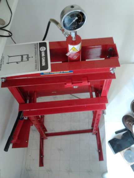
or two in the first few days, and on the 3rd I bought a 20 ton
hydraulic press. I saw this unique unit while browsing in Barclay's
Exchange: it had a hydraulic pump cylinder with a
long handle separate from the press cylinder... and a pressure gauge!
I've always
suspected many of my battery troubles were from insufficient compaction
(verified with the gauge)
and or poor connection between the electrode briquettes and the current
collector plates. Here was a unit to not only apply very high
compacting pressure for the edge compactor and maybe for munching the
electrode and current collector together, but also to know how just
much pressure was in fact being applied.
For the camping trip itself I took the original Peltier
Module cooler I had bought to initially investigate thermoelectric
devices for the refrigerator, and re-assembled it but in a slightly
modified form: I used two 8.5A peltiers in series (electrically)
instead of the original single 5A peltier. Owing to the increased
efficiencies of Peltier modules when driven at lower currents, this
arrangement is theoretically superior, cooling to similar or lower
temperatures with
lower current (~3A versus ~4.2A) from the battery. In fact the unit
cools poorly. The warm side
heatsink does get too warm (~35°c), but I'm still puzzled that it
does no better, the cold side only dropping to about 10°. My fridge
does much better with almost the same arrangement, and it's much
larger. The difference would seem to be two 15v
peltiers in the cooler versus a 15v + an 8v in the fridge. I'll try
some modifications next time - the lower voltage peltier, and a
better heatsink or an evacuated tube radiator.
As long
as the weather was sunny and direct sunlight was accessible (which it
was the whole time), a 65 watt solar panel ran the cooler all day. I
had to move it
around the camp a couple of times every day to keep the collector in
the
sunlight and pointed towards it. Whatever voltage the collector put out
was fine because the cooler had no delicate electronic smarts to burn
out.
Next time I'll
bring a very long extension cord so the cooler can be kept stationary
in the cool shade instead of dragging it around in the hot sun with the
collector.
 After I got
back I kept reminding myself that I had other
projects besides trying to make batteries, some best done in summer
weather, but the cell seemed to be almost
working and I
kept thinking "maybe if I just..." and I kept plugging away at it.
I had thought the
batteries were about there by the end of July, but although the
permanganate-manganese cells would now charge at summer temperatures as
well as winter,
and if heavily charged began delivering worthwhile amounts of current
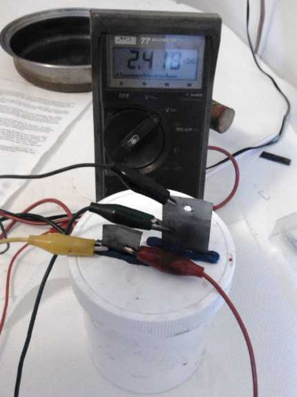
for many minutes at levels of 2.0 to 2.5 volts (even up to about 450mA,
which is over 10mA/sq.cm, or 225mA for over half an hour), they still
had unacceptably high self discharge, losing most of their energy
overnight and sitting at about 2.0 volts by morning. I expect that the
self discharge is the only remaining problem, and that without it
higher currents and much more energy storage giving long discharge
times would be attained.
I made the important step of identifying the discharge
mechanism.
Neither electrode will discharge when immersed in electrolyte by
itself. What happens (I believe) is that a few ions from the slightly
soluble
permanganate dissolve into the electrolyte (contrary to my
previous assertions of having chelated them into position) where they
travel to the other electrode and mutually discharge against the Mn
metal without an external circuit connection. Then, being turned into
solid manganese oxide particles no longer dissolved in the solution,
more permanganate ions dissolve to continue the process.
I'm trying various
measures to block the ions and hence reduce the discharge, with some
improvement but so far no very effective real solution. The other
solution might be to make a simple nickel hydroxide posode. That would
have much
lower amp hours per weight than permanganate and the cells might not
beat lithium ion for energy density.
It does seem that if discharge proceeds under about 1.9
volts that the zinc current collector starts to deteriorate, so the
idea of letting the cells run to lower and lower voltages and putting
them through a DC to DC converter to get a regulated output is out.
They seem to run best from about 2.4 volts draining to 2.0 volts under
load.
I did give other projects some small consideration. I spent a couple more
days trying fruitlessly to repair my 3D printer with the help of an "Arduino Guru"... who
got no farther than I had. I
started in on a V-belt drive for the motorbike and put a 10" V-belt
pulley on the back wheel to replace the chain sprocket. Next it needs a
new (or the same resurrected) motor on the front and a belt tensioning
clutch of
some sort.
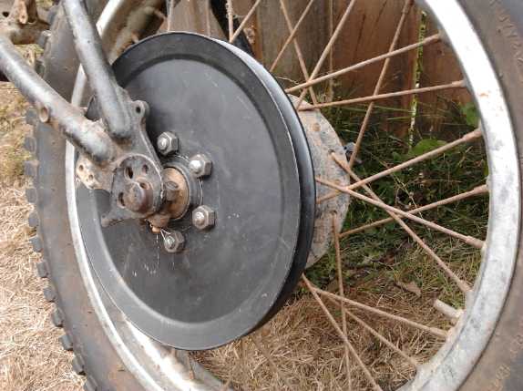
Bike wheel with V-belt pulley.
Belts can slip to provide clutch action. Chains can't.
Wind
turbines seem like something others have done, and done pretty well,
and I'm not in an area with frequent strong winds. So
I haven't tried tackling one myself. But looking again, vertical
axis wind turbines (VAWTs) evidently work much better in the
unsteady
winds with gusts and shifting directions that are most common here when
there is wind, than
horizontal axis propeller
types, and they seem so simple it seems
almost silly not to make one. I'm planning one out. Apparently the
speed is more self-limiting than for propeller types, but if it should
tend to over-rev in strong winds, I have a couple of ideas for gravity
retracted centrifugal fins that will swing out at high speeds to act as
air brakes,
limiting the top speed.
I think I have all the
parts necessary already. I hope to get some other free energy zealot to
put it together.
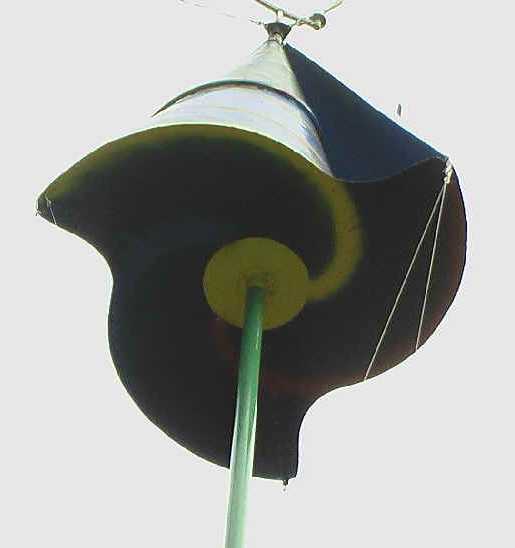
There's probably some "optimum" blade shape, but unlike propeller
types, all sorts of VAWT blade shapes can be made and will spin well.
This one promises easy connection of guy wires at the top (which
requires a bearing up there since the shaft spins).

Alex Erauw says he has "Les meilleur du Monde" ("world's best")
vertical
axis wind turbines (VAWTs).
They start turning in a very light breeze. Evidently he sells them.
Everything above the stand spins so all support must be underneath, but
the unsupported axle section is fairly short.
Presumably the distorted half elipse is an "optimum" blade profile.
I'll try to incorporate such features.
www.youtube.com/watch?v=Mc6JrtpQz34
The thing about doing one
is that much of the system
complexity is in what is done with the rather unpredictable and varying
electrical output, and this little different than for solar, ocean
waves,
or woodstove thermoelectric power generation, so doing a wind turbine
will help
advance the techniques and equipment for the other types as well. The
output can go to the same 12v distribution panel as the solar PV
panels, occasionally providing power including when the sun isn't
shining. I'm not expecting big energy from this (especially in the
occasional winds here), but it's all a part:
everything generated locally is power that doesn't have to be made at
some big plant elsewhere, often by polluting sources, and transported
along long power lines with losses.
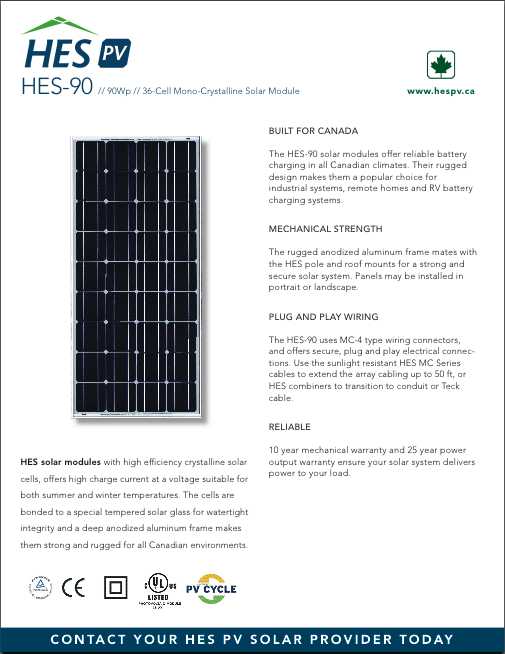
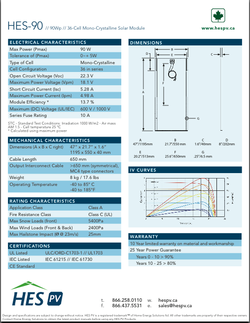
I did a fair bit of shopping, and I saw some juicy 90
watt solar PV panels at HES wholesale that I couldn't resist - just
what I've been wanting for EV use - so (being
a dealer with them) I bought some to use or to resell, and I put them
in the TE
Catalog at 225$. Personally I think that compares well with a 60 watt
panel discounted in a recent Canadian Tire flier to $350. (If I sell
any
I'll buy more for myself.) I could use three on the roof of the Sprint
car assuming I get that going (36 volts), or two on the boat for the
electric outboard (24 volts).
They're just a bit long and I suspect they'll be good for
bumping your head on getting out of the car. Solution: have them stick
out on the passenger side, not my side. Looking now at the
voltage/current graphs, I'd say that instead of using them with charge
controllers, I'd try just putting two of them in series, simply
connected across the
batteries with an isolation diode. This looks just about perfect for
float charging 36 volts of NiMHs or lead-acids, avoiding all
electronics and losses and providing almost the same charging as three
connected through all the 'stuff'. (and they could then be turned the
other way to
avoid bumping of heads.) Of course, that would probably work best with
the collectors facing directly at the sun, which won't be the usual
case on a car roof. Unless maybe they were mounted raised and could
pivot left or right from the center axis.
On the boat I'd have to make a frame and use them for a
roof. (and at that point, should I put in windows and make it a cabin?
then move the outboard controls to the front, inside? all on a 14'
aluminum
boat?)
If anybody around here wants anything items www.HESPV.ca
has
available, for local (Esquimalt) pickup 'cash and carry', I'll pick it
up for a 10% markup plus GST and PST if applicable (no PST
on solar panels). (I may ask for payment in advance.) E-mail or call
me: Craig, 250 384 2626.
In Passing
Incidental news, editorial comments & opinionated rants
Limits to Growth
A celestial being (named Serara, IIRC) suggested to his
audience that for their enlightenment about the coming collapse they
might want to check out a book: Limits
to Growth, by Donella H. Meadows, Dennis L. Meadows, Jørgen
Randers, and William H. Behrens III. This controversial 1972
work, Funded by the Volkswagen Foundation and commissioned by the Club
of Rome, used computer modeling to
explore what happens on a planet of limited resources confronted by
exponential growth of human population and economic activities.
"Five variables were examined in the original model. These variables
are: world population, industrialization, pollution,
food production and resource depletion."
[Wikipedia]
Evidently most scenarios for unguided growth, with various
reasonable values plugged in,
ended up not with simply rising to some equilibrium, but instead rising
to an "overshoot" peak followed by a major collapse. At no time since
the book's 1972 has there been any political will to guide our growth
(other than
China's marginally effectual 'one child' policy), and many of the
projections for peaking evidently bear an uncanny resemblance to the
world today.
The same authors did a 20 year update Beyond
the
Limits in 1993, and a
final update Limits to Growth: the 30 Year Update in 2004. I
confess I've only read articles and abstracts about the books using a
web search, such as the article on Wikipedia.
But even without having read these works, I have the sense
that, having done no population planning, we are very near the apex of
the "overshoot" zone, with a world population (7.3 billion) probably
triple what it
should be over many regions of the globe (...and 2-1/2 times greater
overall than when I was a child myself). The effects are certainly
being magnified and exacerbated by the greed and corruption. Without
that, considering the dropping birth rates in what were "more
civilized" lands, and the more lands advancing, we just might as a
species have managed to plan
better and maintain an even keel. That which hasn't been learned the
easy way must now be learned the hard way.

An interesting comment on global population distribution!
An Educational Documentary
I watched a 2 hour documentary that had a lot of excellent
background on why our society is just now coming apart at the seams,
with 1% of the population having half the wealth and 80% having not
much or even less. First it goes into the diabolical workings of the
pyramid
scheme of the financial system, how the banksters control and enslave
the people and nations of the world by inflicting debt. Then it
explains about
America's
'clandestine empire' which insidiously installs the "leaders" the USA
wants in every country where the resources are coveted and inflicts
crippling debt to control and enslave it, and about the corporatocracy.
I saw it on youtube.com, titled "Life Hidden Truth - 2013
Global Financial
Crisis", but the title when it came on was "Zeitgeist: Addendum". At
the end it brings it back to individual responsibility and
the coming age of greater... humanity. It mentions "The Venus Project"
as a venue to help work towards a sustainable future. [
www.youtube.com/watch?v=Aq-FSI9x6fo]
I don't see how their idea of doing away with money is
supposed to work, unless there's something to replace it with (could I
be too indoctrinated to understand?), but I'm in harmony with many of
their ideas. For example, I've written myself that automation should
shorten everyones' work hours, not cause layoffs and unemployment. And
they mention that
there's no effective democracy, and furthermore, when you step into a
workplace you step into a dictatorship. (My own suggestions that shop
foremen should be elected for a two year term in the Greater Victoria
School District, and that that would bring out the talented and prevent
the indolent or incompetent from rising to such positions by seniority
and holding
them until they retire, didn't go anywhere. It would have been a
start.) Another point is that politicians pass a restrictive law to
solve most any immediate problem (and it would seem with no thought
about the broader consequences of what they're banning or prohibiting),
when improved technology could better solve that problem, because they
know nothing about technology. Those who might deliver technical
solutions have no power to implement them.
Few except banksters understood the financial pyramid
scheme -- until people recently started explaining it on youtube, and
still
most people don't get it: You put 1000$ in the bank, and the bank is
required to keep a 10% reserve. So you think they have 900$ to loan out
at a higher interest rate than they pay you, the depositor, and that
that rate difference is how they make their money. This would be
reasonable.
Instead, they keep all your money and enter on their books
that they have 9000$ to lend out, and they lend it. They have their 10%
reserve - your 1000$. With your 1000$ deposit, the bank has created
9000$ of potential debt out of thin air, which is soon made actual.
The recipient of the loaned money (eg,
the seller of a house)
usually deposits it in a bank, so the bank has 1000+9000 = 10000$ on
deposit and is owed 9000$ (by the house buyer). The interest from the
fictitious 9000$ loan
comes in, and the principal is gradually repaid, so the bank gains more
and
more money on deposit, which they treat the same as your deposit and
lend out nine times as much as they have. The money, created as debt,
inflates the money supply and robs value from your 1000$, said to
amount to 98% of the value since 1913: what cost ten cents back then
now costs five dollars. And the money that exists, all created as debt
to
be paid back with
interest, can never equal the amount owed, so the debts can never
be
repaid. In this game of musical chairs, unless the money supply
continues to expand, defaults are inevitable, and in today's shrinking
economy the banks in many lands have seized major portions of the whole
real estate
'inventory' through foreclosures while tens of millions go without.
If you or I lent money the same way the banks do, we would
quickly find ourselves in jail. Therefore this "ponzy" scheme creates a
two-tiered justice system with a powerful unfair leverage given to the
banking institutions over the citizens. The price of the house was 10
times higher than it could otherwise have become owing to 'cheap', easy
bank credit - supplied from money that didn't exist. The
citizens become economic
slaves to the parasitic banks for decades, effectively on an almost
life-long "rent to purchase" plan - as if it was the bank that had
built and sold them the house! And the financial sector has now grown
far larger
than the real
economy, on the backs of the productive. Only "the 1%" can buy a house
for cash without involving a bank, which accrues a fortune off each
transaction, off each purchaser, with the debt they created out of thin
air.
Again, nations should control, create and print their own
currency, not print
bonds and and sell them to borrow money from a private central bank
that creates the
money out of thin air privately. No private institution should be
permitted to
loan out money it doesn't have - it is in fact (even if not in present
laws)
a criminal offense and
banksters responsible for it should be personally punished the same way
you or I would be. Perhaps there should be no private banks, only
public financial trusts. It's almost beyond belief that unprincipled
politicians have
permitted this insidious, heinous pyramid scheme to be installed
everywhere in the world,
against the interests of their own people. On the other hand, someone
has pointed out that every politician that has tried to end the banking
system's fleecing of the public has been murdered. (This isn't quite
true, as the assassination attempt on Andrew Jackson failed and the US
treasury printed the USA's money for 80 years following his "takeout"
of the First Central Bank, until in 1913 the bankers reasserted their
overlordship.)
The article quoted from below, seen just while I was doing
a
final editing of this newsletter, appears to be a great example of what
can happen when it's done the right way.
Hungary Tells Banksters To Get Out Of Their Country And Take The
IMF With You. (excerpt from article:)
"According to a report on the German-language website “National
Journal,” Orbán has now moved to unseat the usurers from their
throne. The popular, nationalistic prime minister told the IMF that
Hungary neither wants nor needs further “assistance” from that proxy
of the Rothschild-owned Federal Reserve Bank. No longer will Hungarians
be forced to pay usurious interest to private, unaccountable central
bankers.
"Instead, the Hungarian government has assumed sovereignty over its own
currency and now issues money debt free, as it is needed. The results
have been nothing short of remarkable. The nation’s economy, formerly
staggering under deep indebtedness, has recovered rapidly and by means
not seen since National Socialist Germany."
http://americanfreepress.net/?p=12418
.
The
ruling political group was in fact elected on its promise to
nationalize the currency supply as stated. Will this be squashed, or
can it spread to become the herald of a more sustainable way of doing
things? Anyway, congratulations to Orbán, his group, and to
Hungary as a whole!
USA's DHS headed for Syria, Iran?
US president Obama said, seemingly out of the blue last
year, that
if Syria - the Syrian government - used chemical weapons to defend
itself, the USA wouldn't tolerate it. There was no threat or promise
expressed or implied that the USA would help Assad put down the
insurgents if they used chemical weapons, and they were found
by the UN to have used them at least twice with no moves or even verbal
condemnation
from the USA. The statement was thus
purely a threat against the
Syrian government, not a statement of principle against the use of
chemical weapons. And it came after the USA itself had been selling
chemical weapons to the Syrian military. It would appear that the USA
has been supplying arms
and training to any insurgents willing to go into Syria for several
years, and while Assad is
perhaps no more popular than other middle-eastern dictators, the
current problems in Syria seem to be largely "Made In USA". And even if
there was no other criminal intent, Obama is culpable just for
aggravating the situation with his inflammatory statement, which would
obviously tempt the rebels to use chemical weapons and try to frame the
Syrian government for it.
This month's nerve gas event that killed hundreds of
people
just after UN inspectors had arrived on the scene at the invitation of
Syria and Russia,
then,
came as no surprise, and had every appearance of being a stage-managed
propaganda stunt to get the American and western public behind an
invasion of
Syria, similar to Hitler's staged "Poland Attacks Germany" attack just
before
Germany invaded Poland "in retaliation" in 1939, incidentally starting
world war two. A lady in Syria near the scene said it was done by the
rebels and she named a rebel leader who she alleged had ordered the
attack. (See Corbett Report of
August 21st on youtube.com explaining how little rhyme or reason there
would have been to Assad launching this gas attack on his own people,
especially at this time.) Israel claimed to have heard "radio chatter"
pinning the blame on Assad's brother. Is that the best "proof" they
could find? Nor was it a surprise
to hear a rumour
a day later there were American paid mercenaries already next to or
even in
Syria, and within a week that the USA could be expected to attack "any
time".
A bunch of other stuff suddenly started to add up, too.
Why did the American "DHS", "TSA" and expanded "FEMA" really exist, why
did they have
such a huge personnel, and why did they need (according to various
reports) 400,000,000 or 1,200,000,000 rounds of "dum-dum" hollow point
bullets, placing orders to the point that not only the public but the
police can't buy bullets? And why did they need state-of-the-art
armoured vehicles? Why were they said to be using pop-up silhouettes of
civilians for target practice? What was the purpose of them being
ordered (a week or so before the nerve gas attack) to complete various
training programs and, essentially, mobilize, by October, with
placement of large food ration orders? What were the various hints
being dropped that "something big" is afoot for October?
What it seems to add up to to all appearances, is that the
"homeland" forces are going to be sent to Syria. They were never
intended to be employed within the USA - the names were just blinds,
perhaps for the recruits as well as the world. (This blind has worked
well: even the ardent critics of the US government thought they were
meant for imposing martial law at home. I don't how and whether they
were
included in foreign calculations of US military muscle.) The first step
would be
invasion and occupation of Syria, and that's probably all that will be
hinted at while it's happening. That would give the USA a port in the
Eastern Mediterranean. But all these violent weapons and all this force
can hardly be necessary to subdue Syria alone. The obvious next step is
to march from Syria through Iraq and invade Iran - the other country
the USA has been targeting with threats, propaganda and sanctions for
some years now. I wonder how many of those who joined the "DHS" and
"TSA"
had any inkling that they would be headed overseas to invade foreign
countries?
If they are successful they'll
have a "secure" route for transport and oil and natural gas pipelines
to the
Mediterranean through Syria, Iraq, Iran and Afghanistan.
But such plans are
madness. Russian deliveries of missiles to Syria
and Russian naval movements in the Eastern Mediterranean would suggest
they aren't to roll over and take it. Furthermore, the US government
won't
get away with
it at home. American protests that will gradually turn into bloody
uprisings as people wake up to what's being done and why are almost
inevitable. We may look at Egypt as a template.
Speaking of which... it also seems there may well have
been
American influence in the overthrow of Morsi, Egypt's first
democratically elected leader, where they seem to be trying to pull a
repeat of slandering and overthrowing Iran's first elected leader in
the 1950's and installing the Shah as a USA-friendly puppet who would
give them Iran's oil instead of selling it at a fair price, and the
many repetitions of that theme since in South America for resources
there.
But this ain't the 1950's no more. As Zbigneuw Brzezinsky
says, there seems to be a raising of consciousness around the world,
with people everywhere having an increased sense of political
awareness. People are starting to catch on, and government and business
are starting to have a hard time pulling the wool over their eyes.
Furthermore, some critics argue that the US economy will implode,
either simply under the strain or because some countries will cease
shipping their commodities to the US. They say that the other countries
will win this way instead of trying to fight the militarily powerful
USA with weapons, "without firing a shot."
Why is Obama now asking for Congressional approval? Some
think it's a face-saving way of stepping back from the brink, others
think approval through blackmail will assure that the juggernaut will
roll on and give the appearance of solidarity. The latter idea seems
more in keeping with the rest of a plan put into motion well before
Obama's time.
There is of course no hint of the USA wanting to actually
take the steps required to exit the oil dependency that is at the root
of all
this in order to move towards a peaceful world. not even the most basic
step
(taken most everywhere but in North America) of electrifying the
railroads. That doesn't fit the part of the "business model" of the
clique of
gangsters who rule the world from behind the scenes (and for whom Obama
is "an asset") of sapping wealth
from the public (in case there is any left) via petroleum. As
Jesus said, "A
corrupt tree can't bear good fruit."
I'm starting to think that the fearsome collapse of the
global
financial system, and the global chaos and dislocation of plans and
supplies it will cause, can't come a moment too soon! So far, the can
has been kicked down the road farther than many (lately including me)
have expected, but at
some point "the can" will turn into "the bucket". I'm in tune
with those who
advise "Get your money out of the banks!", "Use local banks and credit
unions.", "Become your own central
banker.", and "Have cash, gold, silver, bitcoins, assets, commodities,
food, energy, for the day the banks close their doors." It's not like
banks pay interest any more, and with the threat of "bail-ins", money
in the bank is starting to look less safe than cash in a jar buried in
a field. As Max Keiser recently put it, the world's people are now
not just being fleeced but plucked like chickens.
BC Winter?
Last winter was very cold in many parts of North America.
We were spared here in the PNW, but somehow I have a sense that after
this
great summer there's likely to be an exceptional winter with mountains
of snow here on the coast. Heavy snow may block roads, and bring down
power lines
causing lengthy power failures. It's another reason besides potential
monetary system collapse to have some food, fuel and any vital meds
stocked up. I've bought snowshoes, which I missed having in 1996.
(Remember the 1996
snowstorm when nothing was moving for 3 weeks in Victoria?) We are now
globally seeing various weather extremes and the PNW may not be immune.
People did freeze in the Quebec ice storms a few years ago, and in
Russia last winter. The flooding in Russia's far East this summer
doubtless brought most everything to a halt there, too, and just now
unseasonable early spring snow and bitter cold (-20°c) is killing
livestock and
people in Peru, which is in the tropics. Victoria wouldn't
fare well at -20°c either. The shrinking of the Arctic icecaps
might produce glaciers and colder temperatures elsewhere, especially at
higher elevations. Could it all be
related to HAARP? Who can tell?
I could just be a worrier and Victoria's winter will have
it's usual rain and clouds with occasional frost and a few flakes of
snow that soon melt. Look at all the nasty weather there's been, and
all
the crop failures last year (2012), and decide for yourself whether
it's too much bother or takes up too much storage space to be prepared
just in case there's a nasty weather event here too. Just before
hurricane Sandy, NYC grocery store shelves were emptied in something
like an hour or two.
Challenge for the Next Civilization
Formerly lands were ruled by kings and dictators, then the
concept that people could rule themselves evolved, and democracy and
representative government followed. However, these concepts were new,
untried, and while the greatest minds of the day framed the new
systems, they couldn't see ahead far enough to see the more distant
ramifications of the choices they were making. Their frameworks had
serious flaws that are now proving fatal to peaceful evolution of
society.
In most countries, parliament acted as a
legislative branch under a king, but assumed the powers of both the
executive and legislative branches of governance as soon as there was
an incompetent king. Mostly the judicial
branch was properly separated from the other two. In the new United
States of America, the founders wisely realized that the executive
branch was separate from the legislative (as any high school political
textbook will tell you today), and created the elected
office of president to replace the hereditary executive office of king.
But in no cases did anyone proceed farther with the
actual selection mechanism than the idea of marking the "illiterate's
X" on the ballots for the offices to be filled. (After all, there were
plenty of people who couldn't read or write.) It seemed - and was - a
tremendous advance over elections with swords and spears.
But I've written before about how this primitive voting system is
unfair,
and how it polarizes and politicizes our governing systems and our
whole societies.
In this unfairness, permanent political partisan groups,
"parties", soon begin to form. Quickly power exits the elected
legislatures and becomes concentrated in party hands and it is seen
that "independents" in the legislature can accomplish little when
confronted by organized voting
blocks,
and the voter begins to feel they must vote for a "party" rather than
for a person, and that voting for the best person is a "wasted vote".
It is a fear based voting system where one votes instead for the "most
likely to win" alternative to the "least wanted" likely outcome. As the
polarization proceeds one party gains power over all others combined,
and the legislature becomes merely a rubber stamp for the decisions of
the largest party's leader, who in most nations is also the "Prime
Minister". (a
term first applied derisively to Robert Walpole for his staid,
churchman-like leadership. [Walpole is also of "Bob's your
uncle!" fame for giving his relatives the choice jobs.])
Ambitious people, greedy or hungry for power over
others, start finding their way to the top of the parties, and thence
by default to the top of the political system. And since they have no
guiding ideals or ideas for social progress nor principles except "What
can I get out of it?", but occupy the seats of power wherein such
new ideas and progressive forms are implemented, sociopolitical
progress grinds to a halt, and as events of the new century have shown,
go into
reverse. Former "bastions of freedom" are rapidly becoming brutal
dictatorships.
Similarly minded people who have connived their way to the
top of the economic system are also able to get what they want
politically,
by rewards to the unprincipled party politicians. And now with their
vast stolen fortunes they lavishly support all
political sides - any who may perhaps form the next government must be
beholden
to them. This is why there are
two laws: one for those with the money who get the politicians elected,
and one for the rest of the people. We see today the transfer of the
entire wealth of nations to wholly corrupt bankers and commerce based
people (often the same people, as a handful of families controls 70 or
80% of the world's commerce) by various obscure fraudulent and
underhanded processes, best
described as brazen theft on a grand scale, that would land any of
"the 99%" in jail, with politicans in connivance, aiding and abetting
the crime -- and then choosing not to arrest or prosecute.
A major challenge for the next civilization will be to
frame its democratic and representative governmental institutions in
such a way as to foster election of talented and morally qualified
individuals to governing offices, people with ideals and ideas for
further improving society, while giving the greedy and power hungry
no foothold. Along with treason, betrayal of public trust in
any form
by anyone in any position of political or economic power, must come to
be treated as the culpable offense and capital crime that it really is.
Today getting involved in political processes seems
virtually futile, and the "political class" is more and more separated
from society and reality. The seeming apathy of the masses is due
partly to powerlessness more than to lack of desire or interest in
effecting change. The choice ranking voting system, separation of the
executive and legislative branches, power to control the political
process and agenda through referendums, and (IMHO) the Department of
Progress, are all basic components to fixing this. These things will
empower people to be effective when they get involved in governing
processes, able to provide input and influence to make needed changes
and advance society and culture.
Electric
Hubcap Motor Systems - Electric Transport
Better Rotor Magnet Attachment?
I considered or started in on some things that were going
to need Electric Hubcap type motors or generators. I had been trying to
think of a stronger way to put the magnets on the rotors, and I think
I've come up with something simple: a better pattern of polypropylene
strapping. The biggest problem with the existing method is that the
outer end of the magnet isn't covered. The magnet can simply slide out
if it doesn't adhere well to the epoxy, and this happened to my first
(so far only) Electric Caik rotor at some very low speed. I re-did
the rotor after I sanded the slick coated magnets. I'm still afraid to
run
it above around 2000 RPM, when my intended design speed was 3000.
But I didn't want to add another layer that would make the
cloth thicker on top of the magnets. Axial flux magnet gap is quite
wide, but having placed a wall between the magnets and the coils, the air
gap isn't very big... and I don't want it to become zero or negative
with the magnets rubbing the wall owing to extra layers.
The new idea is to put a first layer of strapping over the
outer end and wrapping it around the sides of the magnet. It would just
be the thickness of the magnet tall and hence add no material on top.
An aluminum clip can hold it in place while the epoxy sets.
When the "regular" strapping is laid on, it would be the
same height, one material thickness over the magnet, but it would
enclose the material now underlying around the sides. The material now
covering the outer end would thus be supported all the way up the
sides. It
could also extend down the edge of the rotor and even wrap around the
back if I feel disposed to cut more complex shapes and extend the
epoxying down and around.
Maybe then I'd feel confident of testing the Caik motor up
to 3500 or 4000 RPM and (assuming it holds together) calling it a 3000
RPM motor as I had planned.
The Electric Motorcycle - with V-belt & clutch
Having somehow not got the Chev Sprint with the
ultra-efficient torque converter transmission working this summer, I
decided I should try out the belt-clutch idea in a simple way: by
resurrecting the electric motorcycle project. This rather heavy frame
machine (plus the rider)
had needed about 80 amps out of an Electric Hubcap motor to start
moving on level ground with a 4 or 4.6 to one chain sprocket reduction.
It was like trying to start a car moving in 3rd gear, and it was pretty
disappointing.
This time I decided to try a 4 or 5 to one reduction with
a V-belt, with an idler operated by a clutch pedal to tension the belt.
On the 27th I made the drive to Princess Auto (and other destinations
in the Langford direction) and picked up another of their flat-plate
10" V-belt pulleys, and a cast steel 2.5" one for the motor end. I
didn't see any ready-made idlers, but that wouldn't be hard to make.
The next day I drilled the bolt holes, turned the center hole larger on
the lathe, and (with considerable filing to fit) mounted the big pulley
on the back wheel of the bike. I'll use a link belt in order to get the
belt through the frame.

The 10" V-belt pulley - with center hole expanded and bolt holes
drilled - on the back wheel.
With the bicycle rim motor unmade, the Sprint car still
sitting, and all the other things I could be doing, I'm not sure this
project is the most effective use of my time. But once it's working, I
see no particular use for it myself, so I won't be fitting it all up
with battery chargers, weatherproof equipment covers, signal lights and
so forth to make it a practical vehicle. I tell myself it should be a
short project. Haha! Anyway,
putting the pulley on was just part of one afternoon.
Mazda: Battery #12
I was told the Mazda would run with 8 to 12 twelve volt
batteries. And so it does. But using regular "marine-RV deep cycle"
batteries, with sodium silicate or not, has shown a problem: they're
not really made for delivering such high continuous currents, often
well over 100 amps on an up slope, except maybe for a moment to start
an engine, and so they run down rather quickly under heavy EV loads,
reducing the expected driving range. Golf cart batteries would be
better, but only uncommon 8-volt ones fit in the Mazda. Also, my 70
amp-hour NiMH "D" cell batteries aren't charging right up to 14 volts
owing to somewhat weak chargers, and they run down prematurely.
Every battery that's added raises the voltage and thus
reduces the current required to attain a given power, and the lower
currents make for more gain than just the added percentage of storage
capacity. I finally got around to juggling some batteries around and
putting in battery #12 on August 31st. (with Tom's help lifting them.)
I expect to go from about 5 miles range with what I think is reasonable
voltage drop to at least 6. Speaking of which, the "Cycle Analyst"
won't say the voltage is above 155.3, and I was worried about why it
wasn't charging higher. But I finally noticed that the other meter says
166 volts, so the Cycle Analyst is wrong.
But the batteries that run out of charge first are the
NiMH ones -- because they aren't charging up to the full 14.0 volts.
I've found Toshiba 15 volt, 8 amp power adapters that aren't too
costly. I have one now. I put it on the lowest NiMH battery with a
smaller value current limit resistor on September 1st, and it looks
like it's charging faster. (I'll order a bunch of them soon but the
cheapest store is presently out of stock.) That'll probably add another
mile or two of range as well, and faster charge recovery although it's
still a slow float-charge system.
But I haven't have time to put the improvements to the distance test
yet.
I picked the float charge
as surely being the easiest on the batteries and hence having them last
longest, with overnight charging. I still think that. But it can limit
driving if you want to drive two fairly good distances on the same day.
But evidently I shouldn't have left the new charger on overnight: it
was still pumping in heavy current and overheating the battery the next
day. I'm worried its capacity may have been reduced or that some of the
cells may be ruptured. It turned out to be 15.5 volts instead of 15.0,
so it needed another diode in series to output the proper voltage.
(Starting with a 14 volt supply would be better, if such a thing can be
found at an economical price.)
Of course, an inefficient automotive transmission is a big
part of the problem. Without its 30% [typical manual transmission]
losses, the currents would be 30% lower and the vehicle would have much
greater range with the same batteries. In spite of all my failures and
setbacks, I trust I'll be able to get back to the variable torque
converter "ultra efficient" transmission project and bring it to a
successful conclusion - hopefully as an "Electric Hubcap" add-on motor
system.
Electric Equipment Projects
Improved(?)
Thermoelectric Camping Cooler
For the camping trip
I took
the original Peltier Module cooler I had bought to initially
investigate thermoelectric devices for the refrigerator, and
re-assembled it but in a slightly modified form: I used two 8.5A, 15V
peltiers in series (electrically) instead of the original single 5A,
15V
peltier. Of course, running the modules below 1/2 voltage, they lose
considerable capacity if the voltage goes down to 10 or 11 volts. But
my plans were for higher voltages if anything, rather than lower.
There was a spot on the warm side heat sink machined flat
for the peltier module. To fit the two modules, I machined it a little
longer (it was too short by all of 2mm or so) on the milling machine.
After putting it off for weeks, I started putting it together on the
evening of the 4th, and finished the assembly on the morning of the 5th
before I set out camping.
Performance during the campout was meager. It was better
than nothing, but not a whole lot. I think the 4 liters of ice lasted a
day or so longer. I didn't have time to look at it while camping. After
I got home, I started checking and found that the two bolts clamping
the warm and cold heatsinks together onto the faces of the Peltier
modules weren't very tight, and the cold side fan was jammed by a part
that was out of place.
With the problems fixed, the doubled module cooling should
be
superior - especially with the limited power usually available while
camping - pumping more heat with less current from the battery
(~3.0A vs. ~4.2A = ~70%). But in a couple of attempts, I haven't proved
it so far. Perhaps I should try the 12v-8v series peltier arrangement
I'm using in the fridge.
A second component to this project was to power the cooler
directly off a 65 watt solar
collector intended for 12 volt applications (putting out probably 12-17
volts while powering the cooler). As long as the weather was sunny and
direct sunlight was accessible (which it was for the whole campout
while the sun was above the trees surrounding the clearing), this ran
the cooler all day from about 8:30AM to 6PM (That's DST, so 7:30 to 5PM
local solar time). I had to move it around a couple of times every day
to keep the collector in the sunlight and pointed towards it. Whatever
voltage the collector put out was fine because the cooler had no smarts
to burn out. I had put a resistor in series with the outer fan to
reduce its speed/noise, and the two 15 volt Peltier modules were in
series
and could tolerate up to 30 volts. The only fan that could be run at
somewhat more than its rated voltage was the inner one. It was a small
quiet fan and I doubt it cares much about voltage.
The one important change I'll make next time is to bring a
very long
extension cord so the cooler can be kept stationary in the cool shade
instead of having to drag it around with the collector in the hot sun.
Electricity (Energy) Production
Magnet Machines: More Magnets?
The type of magnet machine that seems most likely to
succeed might just be the "magnetic ramp" type, with the ramp formed
into a circle. I now envision one where instead of a ramp with two rows
of magnets that gradually get farther apart, it would have just one
row, around the outside as a stator where the magnets gradually get
farther from the rotor, in a one-turn shallow spiral.
Either by repulsion or attraction the rotor magnet would
spin the rotor for one turn until it came back to the start and end of
the spiral. We'll consider repulsion. Normally there it would encounter
the equal and opposite magnetism that would bring it to a halt.
Instead, at the optimum moment some sort of cam would push the last
magnet from the outside of the spiral to the inside, so that the rotor
magnet, instead of being at the end of the spiral, is at its start and
will spin another turn. Some will hold that the force required to push
the magnet into position will be equal to that gained in the rest of
the circuit. If it's less, the machine will be obtaining nuclear energy
from the magnets via their magnetism.
I had some sort of mental block against this type of
machine because one magnet on a rotor pushed by one ramp doesn't make
for much force. But obviously as many magnets as practical can be
placed around the rotor at the best angle, and all of them will be
pushed. The cam will be activated as each one passes the start and end
point... with the others still pushing. The unbalanced component of the
force driving the rotation, which will doubtless be quite small, will
be multiplied by the number of magnets on the rotor, and will be
smoothed out if the magnets don't all line up at once at certain
points, ie if the numbers of magnets on the rotor are slightly
different than the number on the stator.
Hopefully several magnets would overcome inertia and
friction and also be able to do a useful amount of work.
Another Video of Alex Erauw's Vertical Axis Wind Turbines (Aug
26th)
I've been convinced by Erauw's videos that If I ever make
a wind turbine, it'll be a vertical axis one. They seem so
simple, and are apparently more effective in shifting winds and
turbulence: ie, at any location shorter than a tower that sticks up
above
everything else around. (Or as I previously proposed, strung along a
cable between two mountains.) Erauw has some impressive units and
equipment to make them, but
it should be simple to do a small unit with some of the same shafts and
bearings I've been using for motors, a piece of plywood or two
(depending on the unit's size), sheets of aluminum, and perhaps just
connect it to a lawnwower motor or one of my own motors with a flat
belt (or V-belt), rather than build coils and a magnet rotor into the
unit itself.
Since I already have too many projects, I got the idea to
offer to create a design, buy someone the parts, and have them put it
together. This does have the danger of drawing me into assisting with
various aspects, doing charge controllers and hookups, and so on. But
these are things I'm doing anyway, presumably for various types of
power generation. And I have a couple of prospects of interested people.
Let's see... maybe an aluminum and 3/4" plywood rotor
about 3' diameter by 3' tall, unit mounted on an angle iron frame, with
a 1" shaft and bearings below the rotor and a V-belt or flat belt
step-up drive to a lawnmower motor for a generator.
Electricity Storage - Turquoise Battery Project (etc.)

Plastic Jar Cell #1
Self discharge: is interaction between the two electrodes
On August 3rd I ran a load test on the 'new' PP#3-b cell
with the zircon in the negative electrode.
It started with the cell having charged to over 2.5 volts, and ran for
30 minutes until the voltage of the manganese negode dropped to that of
the zinc 'test/reference electrode'. Beyond this, the zinc would start
to oxidize. Since PP#3's original zinc terminal strip had corroded off,
I decided that lower voltage operation was a bad idea after all, and
that discharge to under 2 volts should be avoided. Obviously if the
zinc was allowed to oxidize, the cell wouldn't last long.
A piece of zinc sheet makes a crude reference electrode.
At the pH, 13, it should be ~ -1.20 volts according to the zinc
Pourbaix diagram. (That can only be considered quite approximate. The
diagram is suspect because it doesn't seem to match standard dry cell
voltage near neutral pH, showing ~ -.84 versus the actual ~ -1.07.)
Before
discharge, the Mn negode tested as about 1/3 volt more negative than
the Zn, ie, around -1.5 volts. That meant the nickel
hydroxide:potassium
permanganate posode was about +1.0 volts.
The cell recovered strongly to ~ 2.35 volts. Unfortunately
I didn't get a reference electrode test at that time. After almost 4
hours, it had dropped to 2.15. The negode was still .280 volts more
negative than the zinc reference, or ~ -1.48 volts. This meant the "+"
side was down to around .67 volts, probably accounting for much or even
most of the self discharge and the lower cell voltage. I later realized
the the discharge was interaction between the electrodes.
I charged it up over 2.5 volts again, and put it in the
fridge.
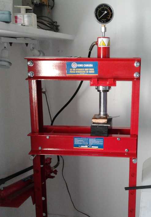
20 Ton Press
"Window shopping" downtown on the 3rd I noticed a "King"
20 ton hydraulic
press with some nice features at Barclay's Exchange. One of its nice
features was a gauge saying the pressure being applied. It was about
380$. After thinking about it I went back later and bought it. I've
long
suspected that
that insufficient compaction might be the reason for the poor
conductivity of my cells, and that I could do a better job of
compacting electrodes. With the edge compactor, 20 tons should be
sufficient, and hopefully more than sufficient.
A key point was the gauge. Previously I suspected that
I wasn't compacting enough, but I didn't even know how much I was
compacting. With the slot in the compactor 3.2mm * 64mm, the area being
compacted is known (2.048 sq.cm) and so from the pressure, the pressure
per square centimeter can be calculated. (Ie, divide by 2.)
Knowing the compaction pressure may be as valuable as greater
compaction itself, because then it's replicable instead of haphazard.
I carried the pieces (it came unassembled) upstairs in about 5 trips,
and completed assembling the beast in the battery lab on the evening of
the 10th - not without having to drill an extra 1/2" hole and mount the
pump cylinder askew to have it on the left side. (Can't move one hole
position and drill 3 extra holes to enable proper left-handed pump
mounting? Come on, guys, 12% of men are left handed!) I pressed some
steel blocks
to about 11
megagrams (Mg, "tonnes", a bit more than a 2000 pound "ton") and it
seemed to work fine.

The new press from above
I then looked up the "optimum" compaction for an Fe 'trode
from the 2004 Bangalore research paper and found it was only "675
Kg/sq.cm". My memory was that the pressure worked out to a very high
figure --
which was probably based on compacting electrodes on the flat. To
compact the 64x64mm electrodes (41 sq.cm) on the flat would take 28Mg.
[megagrams]
But for edge compacting, only 1.35Mg! Had I wasted my money on the
press? But every electrode element would be different, and I can now
try everything from 1 to 20Mg for the Mn and Ni:Mn electrodes.
Perhaps I should consider the possibility that I was
compacting them too much and the impedance problem was that they
weren't porous enough for the electrolyte to enter freely? That seemed
a bit far fetched, but again without a gauge I didn't even know what
pressure I'd been exerting. Using the gauge on the press compacting a
few test electrodes should tell the story!
Late at night on the 10th I thought of a simpler test. I
closed the valve and pumped the press a bit, put in some steel blocks,
and used them as a fulcrum for the same pry bar I had been compacting
electrodes with. I levered up on the press cylinder, with the same sort
of leverage and force I had used to compact electrodes. I could hardly
get the pointer to move on the dial. It must have been less than 250Kg
- at best 1/5th of the force recommended for the iron electrodes, and
perhaps as little as 1/10th!
There was the answer. Much more pressure, easily obtained
with the press, would doubtless make much better electrodes.
When I tried the press on the 12th it turned out the
suggested figure was good: 1.5 Mg was the most force it was prudent to
apply. At 2 Mg the die sheet suddenly bent and had to be hammered
straight again. Later at 1.75Mg there was a "bang" - one of the bolts
holding the press together had stripped its threads. It was also
impossible after applying such pressures to get the bolts out
afterwards with the nutdriver - holding the compactor in a vice and a
good wrench was required. I drilled out the threaded holes in the
compactor and put through longer bolts with nuts.
In theory the book press should be able to provide enough
pressure if it had a working swivel on the end of the threaded press
rod - and it was much faster to operate. Evidently I had wasted my
money on the heavy press - at least for the way I was presently making
electrodes - except for the precious gauge. I finally know how much
actual pressure I'm applying. I now know the lever arrangement I've
been using lately has entirely insufficient pressure.
On the other hand, I could press electrodes up to about 25
or 30 square centimeters on the flat with pressures up to 20 Mg. (hmm,
45 x 45mm = 20 sq.cm = 1/2 the present size, ~13 Mg of press. That
might be a convenient size. The smaller they are the less likely they
are to crack during handling - just stack more of them.) Then they
could be pressed straight onto/into a perforated collector sheet for
best contact, and double sided electrodes with the current collector in
the middle could be pressed, all in one go.
How to Perforate Sheet Metal: Pin Frog?
 I
wasn't satisfied with the roughing up of the zinc sheets
with the rasps - they weren't really perforating - and I kept thinking
about how to properly perforate the metal to obtain a high surface area
grid for better connection. I haven't found such sheets in zinc or
graphite anywhere. I looked on line and found perforating machines, but
they looked like they'd cost many thousands of dollars, even tho from
China.
Then I had an inspiration: Take a plate of aluminum and
use the CNC drill-router (or finally install the CNC kit in the milling
machine) to drill out the desired hole pattern. Then take a bunch of
small finishing nails, grind off the points, and stuff them into the
holes. Screw a solid plate over the heads of the nails so they can't
come out. Drill another aluminum plate, with slightly larger holes, as
a die to press through the zinc sheet and into. Voila! One could drill
a third plate that can left on while puncturing and pried up to push
the zinc sheet evenly off the nails.
Even simpler, just drill one plate and pound the nails
with a hammer (in bunches) through the zinc into a soft wooden block
under. Pry the wood, then the zinc, off the nails - or pound the nails
out again, backwards.
My thought then is to place the perforated zinc (or
graphite) sheet in the compactor and press with it in place, expanding
the thickness of the space a bit and having the die come down next to
it. If it doesn't fold up or crush, this should hopefully make for well
connected electrodes and current collectors.
And if I do smaller size electrodes, it should get easy
enough to make the simple 'bed of nails' with a drill in the hand
operated milling machine: just turn the crank the same number of turns
for each hole position.
I made a 1/4" aluminum test plate with 5 rows of about 30
holes. On the 15th, a friend saw the new creation, and later he
e-mailed suggesting I try a "flower frog" or "pin frog". These are a
block of lead or solder with the pointed ends of nails sticking up from
them. They're used in flower arranging: the stems of the flowers are
stuck into the nails to hold them in place.
The nails proved to be steel and didn't bend when I
hammered on it or put it in the press to punch the holes in the thin
zinc metal (which took about 3/4 of a ton of force, since many holes
are being punched at once). By pressing several times I covered the
electrode area, mostly with multiple offset copies of the pattern, and
had jagged perforations sticking out both sides for good contacts to
both briquettes of a double sided electrode.
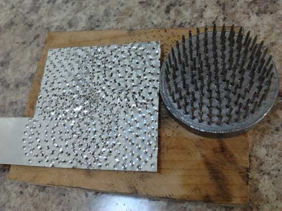
Zinc sheet perforated several times with the pin frog and a hammer.
It easily perforated the graphite sheets, barely moving
the needle on the pressure gauge if at all.
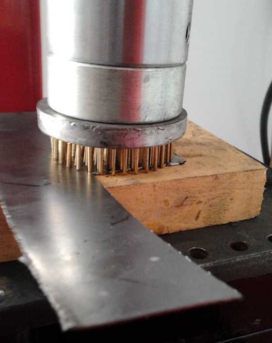 Now the only thing I could wish for would be a larger,
square pin frog to cover the entire electrode area in one pass -
preferably with a denser pin pattern. I checked the web, and found they
do come in various shapes, sizes and materials. Denser pins might be
problematic. Some are wholly unsuitable, eg, some have holes instead of
pins to stick the stems into, so I was lucky Michaels had the right
thing.
But now that I know
what they are, I could probably make one easily enough if I decide it's
worth while. Easier to make than
melting lead might be to cast the nails into epoxy - assuming a thick
slab of epoxy would be strong enough not to crack in the press. ...Or
PP-epoxy composite?
I checked local florist shops. One had quite large round
pin frogs. They wouldn't quite get the corners, but I paid 40$ to
reduce the number of times I have to press for each electrode
(hydraulic presses are anything but fast), or to save having to get
into making a big square one myself.
Plastic Jar Cell #1 (PJC1)
On the 17th I put together the first cell in a (ABS?)
plastic jar. I
cut slots in the lid for the terminals to stick out of. I glued on a
1/4" ABS tab to protect the graphite of the positive current collector.
I "sealed" the slots with modelling clay, since I might want to
disassemble things. My first idea was to do a two-face negode with a
posode on each side, doubling what I had been doing for higher current
and storage capacity, then I decided to just do single electrodes and
see how it worked. The negode was 48g and the posode 30g.
Theoretically, it should have 20 or 30 amp-hours of material.
I backed the electrode briquettes, which had been better
compacted by the hydraulic press than previous ones, with the
perforated zinc and graphite current collector sheets. The posode's
graphite got painted with osmium doped acetaldehyde and calcium
hydroxide. I wrapped each electrode in polypropylene fabric, a thicker
white variety. (called "Crop Cover" of some such name.) Between the
electrodes I also placed a piece of fat, rough embroidery cloth as a
holey place for gasses to bubble out. On the outside of the sandwich I
used two pieces of 3/16" ABS plastic, cut about the same size as the
electrodes. I wrapped this with cable tie wraps then inserted the
terminals through the slots in the lid. I didn't fill it above the tops
of the electrodes - probably they weren't even entirely immersed. I
figure the top will wick up water and work as something of a dry cell.
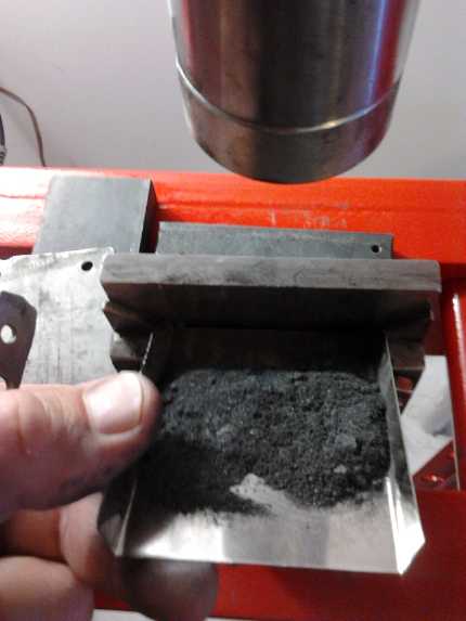
I made a little metal tray to dump eectrode materials into the slot in
the compactor.
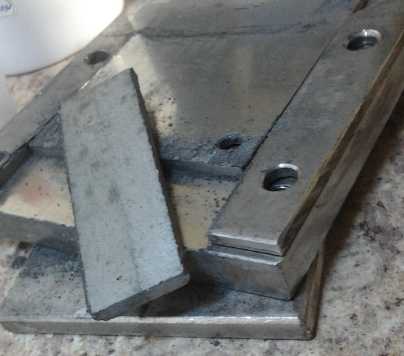
I pulled the first piece of hydraulic pressed briquette out to see what
it looked like:
almost like a chunk of metal with that zinc sheen.
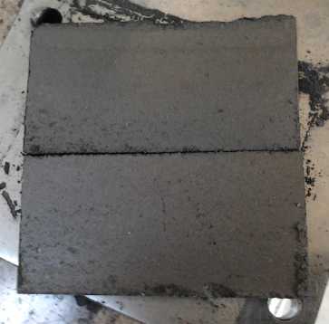
I tried compacting an electrode with considerable material dumped in
for each press.
One can see that the lower end material of each press isn't as well
compacted.
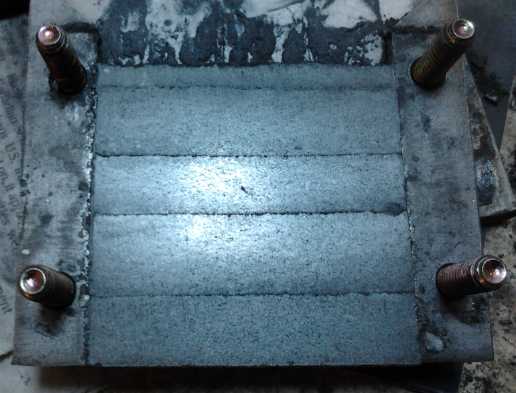
So... it's back to 'one teaspoon at a time'.
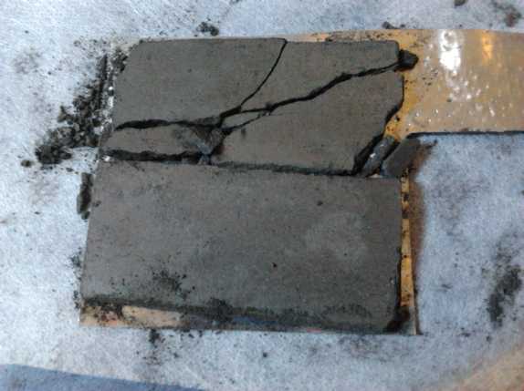
Negode on perfed zinc sheet - still very fragile in spite of high
compacting pressure.
It started out reading over 1.7 volts. This would
basically be the zinc (-) and permanganate (+), with the Mn and MnO2
(in the minus side) having discharged each other to some intermediate
state when I mixed the electrode powder and wetted it. After a day's
charging at 25mA, 50mA and then 65mA, I went up to 90mA. After a while
the charge voltage was about 2.9 volts. I put it in the fridge part of
the time. It seemed to make some difference to the charging voltage,
but it didn't make "the" difference between charging up to higher
voltage and not, as it had without the zircon.
I tried a 1 ohm load test and found it would deliver about
1.2 amps (= 1.2V) after 30 seconds. Doubtless this was draining the
zinc as well as the manganese, but I think it's easily the best figure
so far with MnMn. It's 30mA/sq.cm, which if not high is at least into
real battery territory.
Later I tried it in the fridge and it would only put out
.9 amps. Higher resistance when it's cold probably explains the higher
charging voltages as well as the lower discharge voltage. Apparently
MnMn prefers it warm, at least above fridge temperatures -- as long as
the negode has the antimony sulfide and the zirconium silicate to raise
the hydrogen overvoltage so it charges at "room temperature". (at least
up to about 30°c.)
I tried a short load test and compared it to the first few minutes of
one with cell PP#3. It didn't seem to be faring quite as well, but
close. Well, it wasn't very charged yet. Then I realized I was using a
25 ohm load where the PP#3 test had been a 50 ohm load, so the new cell
definitely had better current. With 50 ohms a bit later it seemed to
fare slightly better than the best test with PP#3 - and after only a
day, I trusted it had a lot more charge to charge up to.
The Mn negode was about .3 to .4
volts more negative than a zinc one, depending on the state of
charge.
It wasn't charging up to the now expected 2.6 open circuit
volts, hovering around 2.4 to 2.5 depending on the charging current,
and dropping relatively quickly. It fared somewhat better in the fridge.
I started to consider that if the cell really had 10 or 20
or more amp-hours in it, tens of milliamps was pretty small peanuts,
and the discharge currents were always puzzlingly low. If indeed I had
a good cell I might not be exceeding the natural self discharge rate,
and so not really charging up most of the manganese. On the 19th I
raised the charging current again, to 220mA. Charge voltage rose to
almost 3.1 volts... then dropped back to just over 3.0. It's such high
voltages that make me flinch - they're ridiculous for any other battery
cell. But why should should they bother me when I've created such a
high voltage cell, with its own unknown characteristics? I went up to
300mA (at 3.15 volts).
I did a 25 ohm load test after 3 or 4 hours, with
the best results so far - marginally: 33 minutes at over 2.0 volts,
46mAH. Later the water was purple (& pH ~7). I replaced the
electrolyte and reduced the charge to 185mA to reduce bubbling.
The next day gave, again marginally, the best results I've
had. But after another day I got fed up with that and tried 670mA. The
water was purple anyway, and the cell *should* have at least 10
amp-hours, not milliamp hours, so why should it be charged with less
than pretty high current? The bubbling was audible and the charge
voltage, 3.6 volts, seemed ludicrous, but when it was taken off charge
after only 1/2 an hour, it stayed well over 2.6 volts for a bit, and
under load delivered the highest voltages yet. I put it back on. But
the graphite terminal had got munched when I had the cell in the fridge
(when I closed the door it pushed it back against a shelf which broke
off the protective plastic tab), and now it finished breaking off.
Attempts to tape another piece of graphite to it were unsuccessful and
it broke off right at the electrode. I disassembled the cell and stuck
a new graphite terminal tab behind the current collector sheet. It
seemed to work okay.
It later turned out that one alligator clip leed or its
contacts had a rather high resistance, almost an ohm, and that the
charging voltage at the actual battery terminals was around 3.1 volts
(not 3.6), with a current of 700mA. Another 50 ohm load test in the
early evening (21st) gave incrementally the best results yet. Most
exciting was that the voltage previously started dropping typically
from under 2.4 in less than a minute, and now it was all but 2.5 volts,
dropping to 2.4 only after 15 minutes of discharge, and it stayed above
2.0 volts for over 90 minutes. That's about 70 mAH at above 2 volts -
not much but improving.
It continued improving. A while later after some more
charging a short 50 ohms load test stayed over 2.5 volts(!) for 5
minutes, and it put out nearly 2 amps into 1 ohm for a few seconds,
instead of under 1.5 amps. Before bed a test with a 10 ohm load stayed
over 2.0 volts (average ~2.3v, 230mA) for 16 minutes (61mAH), and 17
minutes near noon the next day (22nd). This current actually warmed up
the six 1/4W resistors making up the 10 ohms.
I let the cell sit overnight and in the morning (23rd) it
was under 2 volts - essentially discharged, notwithstanding that it was
in the fridge where I had hoped self discharge would be lower. But I
charged it up for some hours, mostly at lower current then at ~700mA
for an hour, and in the evening tried the 10 ohms test again. This time
it ran for 36 minutes (134mAH). This was double, more than
"incremental" improvement!
Evidently it's true: I've been too timid all along,
charging at currents much too low to really start charging the
bulk of the manganese to metal. If it keeps improving with every cycle
until it has a few amp-hours of capacity per pair of electrodes and
good current drive - and if the self discharge becomes manageable -
it's not so important how long it takes to get there.
In the whole discharge region from the highest (2.55v?) to
around 2.05 volts, voltage drop is gradual. From there it sinks rapidly
to about 1.94 volts, then slows again - at that level the zinc starts
to discharge as well as any remaining manganese.
pH is staying around neutral, and the electrolyte is
staying black, obviously with a substantial level, perhaps saturation
level, of permanganate. If it works, do I really care about these
things? Neutral pH is safest to the humans using the batteries.
Self Discharge: Cause... Cure?
Towards the end of the month it was becoming evident that
the self discharge wasn't being overcome. With both stibnite and zircon
additives it would now take charge at room temperature, and one
could
get some real energy out of the cell by charging it hard, but wherever
it started it would still be discharged down to 2 volts overnight.
The mechanism started to look less mysterious, too. One
thing noted was that it seemed both electrodes were discharging, and at
something like the same rate. And on one occasion I stuffed some bits
of plastic under the tie wraps to press the electrodes together more
firmly, and the self discharge then became much higher.
From this one could conclude that the electrodes appeared
not to be each or either one *self* discharging, but discharging
together internally without an external connection.
Then, the separator sheets became black, and the water was black,
but it mostly wasn't permanganate, it was black particles which could
be filtered out - evidently manganese oxides. I had been assuming this
had leaked out of the electrodes somehow... but in cell after cell?
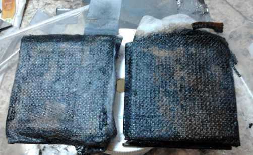
White PP cloth full of black MnO2 oxide.
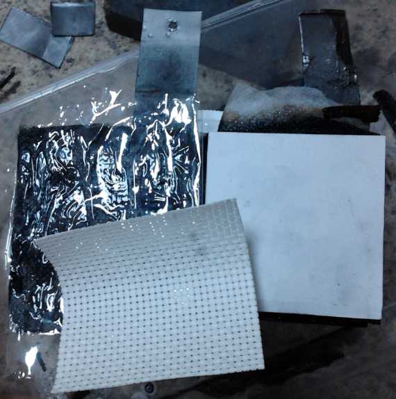
New separators. Could the migration of permanganate be stopped?
This was
in fact heartening: neither the
permanganate electrode nor the manganese metal appeared disposed to
discharge by itself. The electrodes, per se, hold charge fine.
It would seem that it'd be necessary either to use some
kind of containment within or around the posode that the permanganate
ions can't penetrate, or else to abandon permanganate and make purely
nickel hydroxide posodes. The containment of the ions isn't without
precedent, but I seem to have somewhat miscalculated somewhat with the
chelation
by organic ligands, as chelation normally traps positively
charged
ions, in which category MnO4- doesn't qualify. But MnO4 is a fairly
large ion, with an atomic weight of 119, so surely there's small holes
it can't fit through.
But cell #3 seemed to hold charge better as time went on.
I decided to try wrapping the electrodes in things that might be not
just micorporous, but almost nanoporous. The first one was packaging
tape.
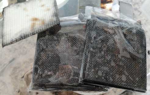
Electrodes wrapped with packaging tape. This was a flop.
This made the battery a virtual insulator. The voltage
could be read, but it would drop to virtually zero with the slightest
current draw. I guess it wasn't even nanoporous. Then I tried masking
tape. After a few hours, the cell would supply just a very small
current, with substantial voltage drop, and it could be charged very
slowly with considerable charge voltage.
But it also held charge better - perhaps in proportion to
the current reduction - taking almost a whole day to drop to 2 volts
instead
of just overnight. This at least seemed to demonstrate that it was the
interaction of the two electrodes causing the discharge. Like many of
the cells, it also seemed to improve over a couple of days, holding
charge longer while conducting about the same amount.
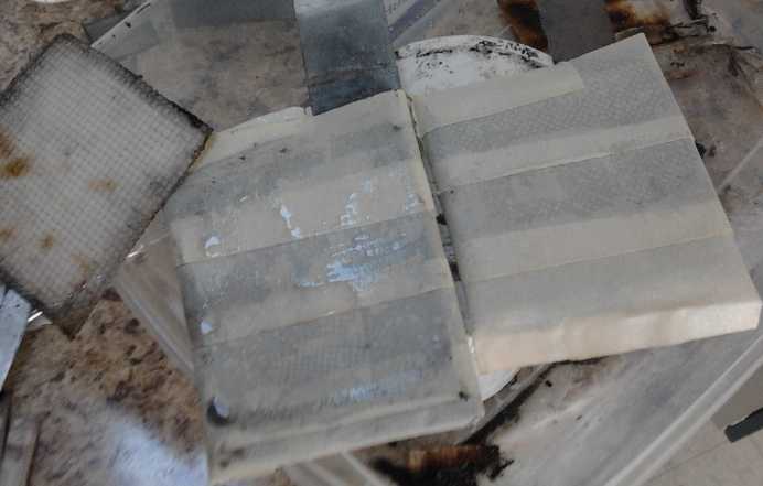
Then wrapped with masking tape.
Current capacity was much reduced, but the self discharge,
occurring via interaction
between the two electrodes, was markedly slowed.
I retained the coarse embroidery cloth in between. (far left)
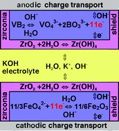
One precedent for the trapping of soluble ions including
negative ones was with
zirconium hydroxide in a vanadium-iron ("V-Fe") 'dissolved ion battery':
On the 29th I painted a good soaking of ferric chloride
into the posode, and
also coated a watercolor paper separator sheet with it, which I wrapped
around the electrode. I also filtered the black particles out of the
water (again) with a cone coffee filter. At some point that day I also
remembered that oxygen discharges the negative side, and I put some
more modeling clay around the terminals to fill the cracks - neglected
with reassembling the cell so many times.
The cell went from 2.53 volts to 2.2 volts overnight, and
the next night from 2.50 to 2.18 in eight hours. This
is still wholly unacceptable; most of the energy has dissipated - but
it's above the usual 1.95 or so. Having noted the trend of the cells to
improve over time, starting
at where they usually improved to might mean it would improve
to the point of acceptability in a week or two. However the first night
didn't show it.
Another thing to try will be ceramic for a separator.
Unglazed ceramic (not porcelain) is very finely porous once fired and
might be just about ideal. In early battery days, clay pots were used
inside glass or other containers. I think I'd rather make thin sheets -
thin tiles, but it must be admitted that electrolyte can't bypass a pot
open only at the top, whereas the electrode will have to be sealed
around a flat sheet. Perhaps I should do a flat vertical slit 'box'
open at the top... if I can make one that doesn't crack in the kiln.
On the 30th I found my ceramic clay, almost 10 years old,
dried out in its plastic bag. It'll take a few days to re-hydrate it
before I can work with it.
Recap: What's been accomplished?
This project
has been long and drawn out, headed for six years now, and I had to
learn a few things doubtless known well enough to others with more
electrochemistry training than I had, and locate materials that are in
fact common enough, but often having unknown names/terminology and from
supply
sources unfamiliar to me - in fact, from many diverse sources. But new
ground has been broken. I explored
all sorts of elements and materials before I picked manganese for the
negative electrode, manganese-nickel oxides for the positive, and
potassium salt for electrolyte, and found the right accompanying
additives, current collectors and constructions to make them work.
And I'm still anticipating finding some way to stop the
electrodes from discharging each other.
A key exploration has been the use of lower alkaline pH
electrolyte. This enables new chemistries, potentially improves certain
old ones, and is far safer than either strong acid or strong alkali.
Instead of sulfuric acid or caustic potassium hydroxide (KOH),
edible potassium chloride (KCl) salt is the main ingredient.
According to Pourbaix diagrams (which I finally 'discovered' after 3 or
4 years), many chemistries work out better at pH 8 to 13 than at highly
caustic 14. If the pH needs to be a specific alkalinity, dumping in
some calcium hydroxide (lime) can raise it to about 12. There may be
ideal alkalinity for a particular chemistry, but so far I've been
finding it doesn't seem very important.
But a lesson it took me 3-1/2 years to learn was that all
metals will rapidly oxidize away to nothing in the positive electrode
at pHes less than 14. They all charge to oxides becoming active
electrode materials, and only carbon/graphite based conductors will
work. It took another year and a half of exploring various materials
from standard dry cell electrode rods to carbon fiber, to find there's
such a thing as "graphite sheets" or "graphite foil". It's
cheap, comes in big rolls and is commonly used for gaskets. It's quite
conductive compared to many other carbon/graphite forms. Then I had to
realize that it can't in fact be made entirely impervious to liquid and
swelling, and find electrode designs with no metal anywhere inside the
cell to allow for that.
No non-caustic chemistries were going to work properly
without this vital background detail in place.
Manganese as a negative electrode was an especially
enticing possibility. Zinc has often been said to have the highest
reaction voltage that won't discharge itself and bubble hydrogen in
water: ~ -1v at neutral pH or -1.25v in alkali. But zinc
gradually dissolves and grows dendrites during charge and discharge, so
zinc electrodes are generally short lived, with gradually decreasing
cell capacity. Looking over the elements I noted that manganese is
-1.19v in neutral and -1.57v in pH 14
alkali, a little higher than zinc. It has no soluble states in the
negative charge areas, and has no insulating states of charge, so it
should last indefinitely.
I have now proven my idea that if zinc could be made to
bubble less hydrogen when charging by use of additives to raise the
hydrogen overvoltage, going from "just works" to "works better", then
manganese could probably go from "doesn't quite work" to "just works"
the same way. The "just works" was shown when it worked but only at
cool temperatures (<~20°c) with antimony sulfide (1%) added.
With zirconium silicate (3%) added as well, it's better than "just
works" - it charges fine up to at least 29°c, the highest
temperature I happened to test when I put the cell in warm water for a
while.
Manganese probably makes the highest attainable voltage
for an
aqueous negative battery electrode. It also has the most amp-hours per
weight, since manganese has a lighter atomic weight than zinc, cadmium
or iron, and forms the same two-hydroxide compound (Mn(OH)2,
Cd(OH)2...) when discharged. Thus it has the highest specific energy
figure attainable, over 1000 watt-hours per kilogram of manganese.
(theoretically, using -1.18 volts: 1158 watt-hours/Kg.)
It also developed that zinc, perhaps ironically, is a good
and perhaps the best material to use for a conductivity additive and
current collector, with only a few metals having themselves a high
enough hydrogen overvoltage not to bubble hydrogen at manganese's high
potential and discharge the electrode. (Lead and bismuth are other
possibilities. Graphite might or might not work.) Using zinc does
constrain the electrode to not being too far discharged. If the voltage
gets down to zinc's voltage, it starts behaving like a zinc electrode
and the zinc gradually dissolves. Thus we do have one more type of
battery that does get damaged if it's run down to nothing. But that's a
small point in an age of battery monitoring and management devices for
larger systems like solar installations and EVs.
The crux is we now have a superior type of battery
electrode that didn't exist before, that extends the voltage and energy
density possibilities of aqueous batteries. Probably it could be used
with a typical nickel (hydroxide) electrode with a cell voltage of over
2 volts. The positive current collector at a pH less than 14 would have
to be graphite rather than nickel plated metal. (I haven't tested this,
so it's just possible there would be some unforeseen problem like
bubbling of oxygen with the higher voltage of nickel oxyhydroxide at
lower pHes. If so, again additives to raise oxygen overvoltage, eg
samarium oxide, could take it from "not quite" to "just works". It
doesn't seem to happen with the nickel hydroxide-permanganate mix.)
For positive electrodes, potassium permanganate has
probably been used before, but not in the way I'm employing it.
http://www.TurquoiseEnergy.com
Victoria BC

 I went camping
from August 5th to 9th, so not much R & D work was
done near the beginning of the month except an MnMn battery experiment
or two in the first few days, and on the 3rd I bought a 20 ton
hydraulic press. I saw this unique unit while browsing in Barclay's
Exchange: it had a hydraulic pump cylinder with a
long handle separate from the press cylinder... and a pressure gauge!
 After I got
back I kept reminding myself that I had other
projects besides trying to make batteries, some best done in summer
weather, but the cell seemed to be almost
working and I
kept thinking "maybe if I just..." and I kept plugging away at it.


 I
wasn't satisfied with the roughing up of the zinc sheets
with the rasps - they weren't really perforating - and I kept thinking
about how to properly perforate the metal to obtain a high surface area
grid for better connection. I haven't found such sheets in zinc or
graphite anywhere. I looked on line and found perforating machines, but
they looked like they'd cost many thousands of dollars, even tho from
China.
 Now the only thing I could wish for would be a larger,
square pin frog to cover the entire electrode area in one pass -
preferably with a denser pin pattern. I checked the web, and found they
do come in various shapes, sizes and materials. Denser pins might be
problematic. Some are wholly unsuitable, eg, some have holes instead of
pins to stick the stems into, so I was lucky Michaels had the right
thing.


