Turquoise
Energy Ltd. News #68
Victoria BC
by Craig Carmichael - October 4th, 2013
www.TurquoiseEnergy.com
= www.ElectricCaik.com
= www.ElectricHubcap.com
= www.ElectricWeel.com
Headlines:
** CMBR: Abundant, omnipresent, free radiant energy is real and
it can be tapped!
** High energy storage Mn-Mn Batteries are working! - High self
discharge drops off 'all by itself' over weeks.
Month In Brief
(Project Summaries)
- "Discovery" of free, abundant, omnipresent radiant energy: it's
well known to astronomy as "Cosmic Microwave Background
Radiation" (CMBR or CMB). ...So that's what all those 'free
energy'
people have been groping for without being able to name it! - Other
stuff - Mn-Mn battery project - More other stuff getting left behind -
Thermoelectric Fridge performance update - 3D printer repair.
In Passing (Miscellaneous
topics, editorial comments & opinionated rants) (none)
Electric Transport - Electric
Hubcap Motor Systems
* More Mazda - NiMH Battery Tube Stuff: reduced from 3 to 2 NiMH
batteries, increased them to 90 AH each.
* Front suspension adjustment (it adjusts!) - new brake pads & shoes
* Cable to monitor any single battery: uncovers 2 unexpectedly
weak batteries... that tested 'okay' when the car wasn't going.
* Replaced: 2 "new" ("reconditioned") batteries increase range &
reserve (8-9 miles/13-15Km?)
* Quick defoggers: small 12v heater-blower dies fast with small
battery. 120v hair dryer before starting works well, windows stay clear
surprisingly long.
Other "Green" Electric Equipment Projects
(No reports)
Electricity Generating
* Vertical axis wind turbine from PVC pipes, my motor shafts &
bearings, lawnmower motor as generator. (Sigh, not finished)
* VLF Radio Wave/power line waves Power Pickup unit: made one - little
bang for
the buck.
* "Space Energy", "Zero point energy", "Vacuum energy" etc, etc...
Really means
CMBR !?! - Wow!
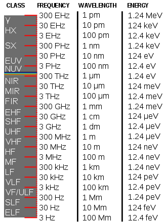
* CMBR = "EHF" radiant energy, between microwave and far infra-red
bands, centered on 1.8mm, 160 GHz.
* CMBR is "omnipresent", comes from all directions, and
penetrates Earth's atmosphere.
* CMBR constitutes "most of the radiant energy in the universe".
(Wikipedia)
* Tesla, Moray, Markovitch, and quite a few others: CMBR energy
pickups/converters/electrical
generators?
* Simplest pulsed coil "TPU" CMBR harvester - has been replicated by
third party.
* Dropping other electricity generating projects? - Geothermal.
Electricity Storage - Turquoise
(MnMn) Battery Project etc.
* The high self discharge gradually drops off (maybe ceases?) by itself
over a period of weeks. All you need to do is wait!
* Mn-Mn, permanganate-manganese, batteries may now be considered to
be working!!!
* They can be used from 2.5 volts and gradually drained down to as low
as 1.5 volts without damage.
* The negode appears to remain more negative than zinc for the entire
discharge (so theoretically the zinc current collector and zinc powder
additive won't corrode) - it's more the poside that loses voltage.
* Utilization of active substances and performance could still be a lot
better.
* Improved soldered NiMH dry cell battery packs. (well...
improved over
my previous techniques...)
No Project Reports on:
DSSC
solar cells (will probably abandon), LED Lighting, Pulsejet steel
plate cutter, CNC Gardening/Farming Machine (sigh, maybe summer 2014?),
Woodstove/Thermal Electricity Generator (will probably abandon),
Peltier & vacuum pipe heat
pumping, Ultra-efficient torque converter transmission, individual EV
battery monitor (will probably cancel).
Newsletters Index/Highlights: http://www.TurquoiseEnergy.com/news/index.html
Construction Manuals and information:
- Electric Hubcap Family Motors - Turquoise Motor Controllers -
Nanocrystalline glaze to enhance Solar
Cell performance - Ersatz 'powder coating' home process for
protecting/painting metal
Products Catalog:
- Electric Hubcap 4.6KW BLDC Pancake Motor Kit
- Electric
Caik
3KW BLDC Pancake Motor Kit
- Sodium Sulfate - Lead-Acid battery longevity/renewal
- NiMH Handy Battery Sticks, 12v battery trays & Dry
Cells (cheapest NiMH
prices in Victoria BC)
- LED Light Fixtures
(Will accept BITCOIN digital currency)
...all at: http://www.TurquoiseEnergy.com/
(orders: e-mail craig@saers.com)
September in Brief
CMBR
A fantastic
development
occurred in September. I saw the term "space energy" that we should be
able to harness easily, from a source I deem credible. I started
thinking about all those vague, undefined and unexplained terms people
were using: "vacuum energy", "source energy", "zero point energy",
"radiant energy", the
"cosmic carrier field". Skepticism and incredulity about such things is
inevitable when none of the proponents of such ideas are able to
identify any source of such energy.
As I looked into possibilities, somewhere my mind made a
seemingly
obscure connection: I thought of the
"cosmic
microwave background radiation" ("CMBR" or "CMB"), well known to
astronomy. Every time CMBR is mentioned, the next
phrase
is about how this radiation is "left over" from the supposed "Big
Bang", and hence "is evidence for" this specious theory about the start
of the universe. It sounds so trivial. AFAIK it's never been discussed
for its own merit or in any other connection, still less ever mentioned
as a potential
source of energy. In Wikipedia I read
through many paragraphs of this, but found a few gems buried within all
the blather. The best one was this: "Most of
the radiation energy in the universe is in
the cosmic microwave background." Bingo! This was what all those vague "free energy" buff
terms were groping at. There is indeed a free radiant energy other than
sunshine, available throughout the universe, and this was it.
The CMBR has some interesting properties. It's called
"microwave", but its frequency band in the electromagnetic spectrum is
five octaves above the "microwaves" used in microwave
ovens, the center wavelength being around 1.8mm rather than several
centimeters. (So... why are they called "microwaves" rather than
"centiwaves"?) That's much greater than the difference between
ultra-violet
and infra-red, which have considerably different radiative effects.
The CMBR penetrates Earth's
atmosphere to the ground, but it obviously doesn't cook everything or
kill life. It seems to be all around yet unseen and having no notable
effect on anything. Being a few octaves above typical microwave
frequencies and a few below the far infra-red, it occupies its own
unique frequency band in the electromagnetic spectrum.
Apparently, the energy available from CMB rays is perhaps 50 times
as strong as that from sunlight - or from any other radiant energy.
Knowing that there actually is a radiant energy available,
and that the likes of Tesla and a fair number of other more recent
inventors have
managed to turn it into electricity - and seemingly abundant
electricity - puts a whole new complexion on trying to harvest "free"
energy, and a whole new focus on what might be best for me to attempt
to create next. Energy
saving devices and greater efficiencies, while valuable, take a second
place to the likelihood
of being able to
make very substantial levels of electricity on demand, day or night, in
any weather.
Techniques and circuits for harnessing this energy aren't
entirely trivial and obviously from the many terms describing it, it
hasn't
been very well understood even by those who've successfully made
electricity from it. Tesla understood it was "radiant energy" he was
harvesting, and someone recently told me that in addition to lighting
light bulbs, Tesla drove around a Detroit Electric (electric car) with
no
batteries, using his energy receiver for power. This is an amazing
story I hadn't heard before. Others have said it was "EHF" energy, but
again without naming a source for that energy.
So far it seems that all such technologies have been
ruthlessly quashed by the gangster-parasites who have controlled our
society,
before much how-to knowledge about them spreads, with typical stories
of vandalism and threatening, beating and probably murder of the
inventors over the decades. The US patent office even
"lost" a patent for a working 50KW device in the 1930s.
As the days went on, every thought and conversation about
solar collectors, wind power, efficiencies and effectiveness of
systems, and the ubiquitous topic of batteries and vehicle range,
became a graphical illustration of what a game changer free radiant
energy would be: electric camping stoves and coolers, quiet electric
cars and
buses with unlimited range, electric trains with no overhead wires or
electrified rails, quiet
electric aircraft, power for spacecraft, the speedy end of gasoline
powered vehicles, eventual elimination of ugly overhead power lines and
electric
bills... and doubtless I've missed many more subtle improvements to our
lives.
These are a few of the things we've been missing out on
for many decades because our society has tolerated fear, greed and
corruption and somehow allowed ruthless gangsters and their sycophants
to rise
to the positions of power and influence and run roughshod over us and
over our real elite: those with ideas, ideals and drive for making a
better world! What could our world be like if these people were in
charge instead?
But the day is almost
upon us that the inbred family cliques who today control 80% of the
world's economy will have no more power to force everyone to buy their
dirty energy products and live lavishly off the backs of the
productive. The internet is starting to expose their dirty little
secrets, and the coming financial collapse will eliminate their power
bases. And some of them are even now changing their own attitudes and
beginning to realize that not only everyone else but they themselves
and their children will live better, happier lives with a reframing of
our society and its institutions as well as long overdue energy
technology advances.
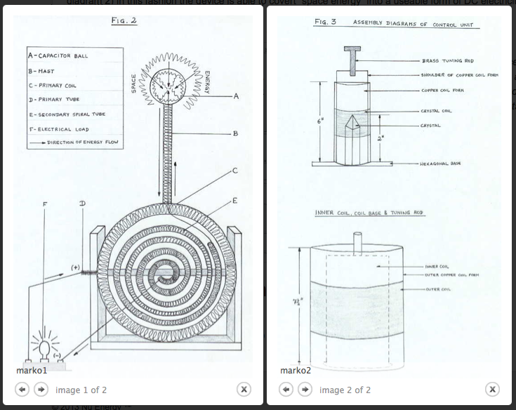
I've decided to go ahead with a relatively simple demo
unit based on a 2007
"open source" design that was apparently duplicated by another party
from the PDF instruction file. It has a double ring 'collector coil',
three 'control coils'/transformers at 90° to the collector loop for
magnetic interaction,
and a rather complex and poorly understood driving circuit of two or
three independent sharp-edged square waves at frequencies in the x100 s
of KHz range. Probably in
the complex interactions and harmonics of these distributed signals is
hidden some heterodyne (beat) frequency that converts 160 GHz to some
far lower frequency that flows through wires, and that electrical and
electronic devices respond to.
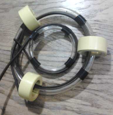
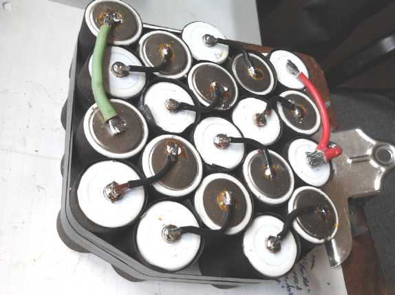
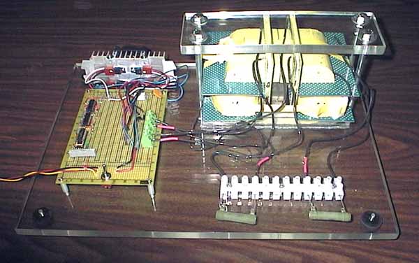
My start at a CMBR energy harvesting/collecting/converting unit.
The secret is doubtless more in the control frequencies and driving
electronics than in the exact physical configuration. (The yellow
iron-powder cores are for the control coil-transformers, which have
yet to be wound.)
Shortly before I got onto CMBR, I had started thinking
about resurrecting an ocean wave power project with the highly
effective,
safe, economical design I'd seen last December (see TE News Dec. 2012).
A fixed tower installation by the shore would need to be built if
it's to be properly tried, and it should be properly tried if it's to
be tried at all, or else the skeptics will point to one more failed or
marginal attempt to harness a new energy source and it'll be doubly
hard to try the next time. But at what point does one make an approach
for support with an untested idea?
On the other hand, what is a million dollars in research
& development investment if it proves the same power can be made
for 2 or 3 billion dollars instead of the 8 billion or more for the
Site C
Peace River dam, and done in incremental stages instead of the "all or
nothing" dam?
About the same time, as a personal power making project, I
cut 8 vanes for a simple
vertical axis wind turbine ("VAWT") from PVC pipes I already had, and
formed
them into the apparently optimum "J" shape, softening the plastic in
the oven at 250°f. This could mount in the attic of the
house when completed, with just the turbine part above the roof peak,
via a small hole in the roof for the shaft. The DC lawnmower motor
planned
as a generator would feed the low voltage box in
common with the solar PV system -- which virtually stopped producing
later in the month as clouds and rain set in.
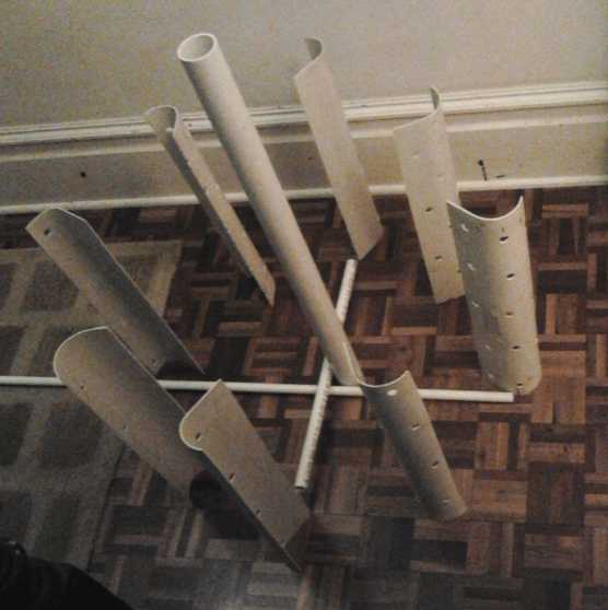
Layout for the vertical axis wind turbine.
After the ocean waves, wind turbine, and radio energy
harvester, I found the CMBR and it seemed like a better thing to invest
my time in.
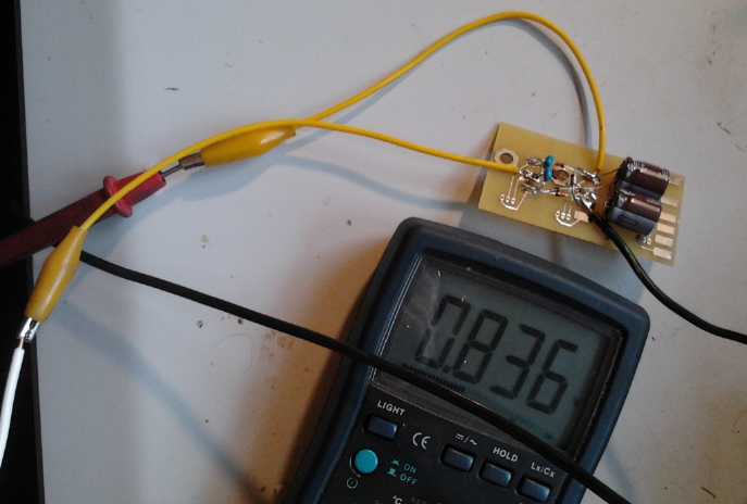
"RF Energy Harvester" circuit connected to 10' antenna wire - here up
to
.836 volts and slowly rising.
Another major
development was that the battery made in August, "PJC1" (Plastic Jar
Cell 1), gradually started holding more and more charge longer and
longer. That this would happen could only be hinted at in my previous
short lived cells. In August I identified the self discharge process
and the logical conclusion was that my chelation idea wasn't working
well enough to use. Still, they seemed to slowly improve, and finally I
have a cell that's lasted long enough to see the process continue for a
while - I won't say to complete.
It does seem it just needs time and charging to gradually
take effect. Seemingly, all one has to do is charge and wait for good
performance. It might take 2 or 3 months to reduce the discharge to
"trivial" levels.
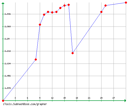
Improving charge retention with time, with a 'reset' when I opened the
cell and made a change.
(Y: cell voltage after ~8 hours; X: September date)
A possibility for a swiftly ready cell would be Ni-Mn at
"moderately alkaline" pH, but further tests on that combo at pH 14 in a
Changhong cell showed that the Mn doesn't seem to hold a charge, even
in the fridge. If it can be made to work, I haven't proved it yet. At
lower pH it should work, but it won't have the higher amp-hours of
Mn-Mn. And I haven't actually tried it yet.
I also made up a couple of soldered Ni-MH dry cell battery
packs, there being no other way to fit the cells in place. However, I
made two great improvements to my previous soldered packs:
1) I cut pieces of tarpaper and wrapped each cell. If the cells get
overheated and melt the thin plastic sleeves, they won't short together
and the pack go up in smoke.
2) I soldered them together with some flex: curved lengths of #16
stranded, insulated wire, instead of the solid, heavy "bus bar" pieces
that were gradually breaking loose their solder joins with vibration in
my previous soldered packs.
I trust the new packs will be safe and last long.
A view of a 12V, 20AH soldered pack, one of two for a 24V cordless
lawnmower.
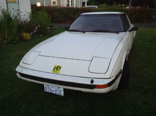
And of course I did a few things to improve the electric
Mazda RX7 and keep it running. I got the front-left suspension up off
the bottom, and changed the front brake pads, which were worn right
down and had started a grinding noise. Defogging with a hair dryer
before starting seems to keep the windows clear for the duration of a
trip.
I didn't make a monitor to monitor and display every
individual battery while driving, but I did make a cable to plug any
one battery into a voltmeter so it could be watched while driving -
just unplug its charger and plug in the meter cable. This disclosed
that a suspected battery was okay, but a couple that seemed okay when
the car was stationary had to be replaced. The replacement improved the
range to the best yet, probably 8 to 10 miles. So far I've only gone
7.0 without a charge, but it seemed to have some range left. Anyway,
best to have some reserve to retain longer battery life. Five of the
nine Pb-Pb batteries now have sodium sulfate to improve their life
span. The others are either "sealed" types or are at mid-life, a time
when it's inadvisable to add it.
Of course removing the batteries and putting in a CMBR
energy receiver(s) for indefinite range would make an individual car
battery monitor unit obsolete, so again my time is probably better
spent doing the CMBR project. If I make good progress on that, I'll
cancel the battery monitor unit project entirely.
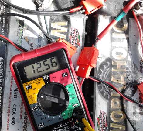
CAT plug to voltmeter pins cable allows watching suspect
batteries while driving,
tho only one at a time.
Other projects continue to get left behind. The pulley for
the Sprint car transmission has sat on one side of the workbench all
summer, no new LED globe lights have been made, and (even having bought
the desired threaded end stoppers in August) I haven't evacuated
a pipe to try improving the thermoelectric fridge and eliminating the
fan. (Fridge performance update: I've been letting it run 24 hours for
a while, and
in the cooler weather the outside of the melting ice tray has frosted
up and it's 1°c at that end of the fridge, and 7° at the top at
the far end (the lowest yet). Occasionally I leave it
off at night and some of the ice melts, cold side temperature rising to
4 or 5°.)
After a last attempt to get the 3D printer working again
which produced only a scary (but fortunately curable) failure of the
netbook computer when I plugged them together via USB, I ordered a
replacement "Melzi" 3D printer control circuit board. It hadn't arrived
by month's end.
Electric
Hubcap Motor Systems - Electric Transport
More Electric Mazda stuff:
Individual battery monitor, battery
replacements - NiMH Battery Tube Stuff - Low front suspension, brakes -
Quick windshield defogger?
Batteries
I finally considered
that if the NiMH batteries seemed to be the ones limiting the driving
range, probably by not getting fully up to 14.0 volts and a full
charge, and now having instead overcharged and damaged some of the
cells with the new charger taking them over 14.0, that I would drop one
of the NiMH batteries
from the car, leaving room to expand the other two from 70 AH to 90.
(One drawback: it now needs quite a long wire to connect from the far
end of the NiMH tubes to the next battery in the string. But the extra
long #2 AWG wire that I happened to have handy doesn't seem to get
warm. Another drawback is that I can now fit only 11 batteries again
instead of 12.)
I know the available amp-hours drops considerably at the
sort of high currents needed for a typical electric car, but it seems
almost incomprehensible that I can only drive 10 or 12 amp-hours of
distance from batteries rated for 70 or more amp-hours. In
disassembling the NiMH batteries, I discovered that yet another tube
had come unglued and probably wasn't contributing - just a small piece
of the answer. It was the "+" end
as always, leading to the thought that I invariably glue on the "-" end
first and set it aside to harden. The "-" ends have been 100% reliable
as best I can recall.
When I do the "+" end, I push on the end cap by hand to
put some tension on the
battery connections. This probably means it gets moved around a
bit while it's hardening. So, new procedure: put a weight on the end to
apply the pressure and don't move it until it's solid. Actually that's
the original procedure... I just put the awkward weight jig aside
somewhere and stopped using it - I guess I got lazy, and I didn't think
it mattered. Evidently it does.
With the two remaining NiMH's now at 90 AH each I went 6.8
miles/10.9 Km on one charge on the 10th, using 16AH. (That's 16 * 132
volts = 2112 watt-hours.) One NiMH and one PbPb were
pretty much down to 12.0 volts. The other nine could have gone farther,
and 2 or 3 of them were still like unused (12.7+ volts) and obviously
could have gone much farther. It would seem those are the sort it needs
for real range. In the meantime the one lead-acid should probably be
replaced and the one NiMH should have slightly higher charge voltage
applied or maybe some of the sets of cells should be replaced.
I still ask, why do 80-95 AH batteries only give 16 AH of
driving? One can't
hope for anything like 80 at high discharge rates, but why not 25 or
30?
Individual Battery Monitor
If I haven't
been able to get going on the microcontroller
ciruit to have bar graphs for each battery's voltage, I could at least
make up a fairly long adapter cable from a CAT socket to voltmeter
pins, to check
one battery at a time while driving, with the meter on the dash or
passenger's seat, and perhaps get some answers to
the above question. For batteries with only one plug, I simply unplug
the charger and plug in the voltmeter for the test. This shows a
real advantage of having standard 12V plugs & sockets, ie, the "CAT
Standard". Of course, large aligator clips onto the battery posts would
probably work okay too - at least for the batteries with posts.
This did indeed give answers. When the overall voltage
started dropping rapidly, after only 2-1/2 miles by the time I made the
cable, I found two identical PbPb batteries labelled "Workaholic" that
read
fine when not under load, but one dropped to about 7 volts and the
other as low as -2 volts when I pressed the accelerator while driving.
Somewhat unexpectedly, those were the ones now limiting the driving
range. These were donated by Jim Harrington and I'm grateful I was able
to use them for some months. But they're 'sealed' cells so I don't
think they can be renewed.
Replacing them with earlier 'renewed' batteries only made
it worse. One 'deep cycle' one that I had previously been using in the
car for a while dropped seriously in voltage under load, eg to 8 or 9
volts, even
when it was fully charged - it simply couldn't handle high currents. I
had been unaware of that all along. There was virtually no way to know
it without
an individual reading while driving.
So I bit the bullet and bought two "reconditioned"
batteries
which were quite new and put them in. The first test drive of 3 miles
showed less voltage drop. Then, since they were both still quite new, I
put
sodium
sulfate in them.
The two remaining
NiMH batteries, now expanded to 90 AH but which I was still worried
about, tested fine. Probably now the range is limited by the
two size 24 PbPb batteries that are at the front-left where two size
27's won't
fit. However, a 7.0 mile drive showed there was still some reserve, so
it'll probably go 8 to 10 miles now if I need to stretch
it that far. But it's better for the batteries to have the reserve and
not discharge them to the max. It's still an "in town only" car.
Suspension
I got the left front suspension cranked up off
'bottomed out'...
literally. Under a plastic center cover, there's a nut at the top of
the strut/shock
absorber that you crank and crank and crank, and gradually the corner
of the car
rises. The shop manual doesn't mention that adjusting the front
suspension is possible and I've never heard it anywhere. I only found
out that's how it works by
buying a deep socket to
fit into the recess and trying it, after noticing that the nuts were
greased, which is unusual. The one on
the other side takes a different
size socket wrench... so the left one was apparently replaced after the
accident (before I got the car), by a different type... and
evidently never adjusted afterwards. The left side still sits an inch
lower
than the right, but I turned it a long way I don't know how far to dare
to go. The main
objective, suspension!, is accomplished and the car rides much nicer.
New Brake Pads
I also bought new front brake pads on the 11th. I was
getting some increasingly nasty grinding sounds lately
when I braked hard - and there's no regenerative braking or any other
way to stop the car if the brakes
don't work, other than the hand brake. The brake pads were indeed worn
right down, with metal
rubbing on the disk in one spot.
I had trouble
getting the seized tires off. Just as I
finished the whole job, a mechanic happened to walk by and said "That's
easy! Just loosen the wheel nuts a bit, get in and turn the steering
wheel back and forth. They'll pop right off." Ahrg!
I figured the rear brakes doubtless needed doing as well,
and that won't work for them.
I loosened the nuts a bit and drove back and forth a bit, punching the
pedal in low gear and reverse. A wheel came off fine, but the rear
brake shoes were almost like new. Too bad I had already bought new
ones. It'll be a long time before I need them.
Windshield Defogger?
Quite a while back I got a small heater that plugs into
the cigarette lighter. The heater installed under the dash by the
original converters of the car evidently had almost immediately blown
its internal fuse and wasn't
very accessible. Naturally I want to replace this with a Peltier module
heat pump rather than spend time on a heater that uses up a lot of
power. For a quick means of defogging the windshield now that fall is
here, I decided to mount the little heater on the dash and aim it at
the windshield. (Aim is adjustable.) Unfortunately the cigarette
lighter doesn't seem to work. Sigh! I threw a 12v NiMH tray battery
with a cigarette lighter socket soldered to it into the car. Then I
decided not to bother mounting the heater, either, and just have it
handheld. It works. Hopefully need for it will be rare.
A 120 volt heater, eg 300-400 watts,
placed in the car and turned on to warm the car up and (hopefully)
defog prior to a trip while still plugged in/charging should do the
bulk of the work.
Mazda Project Eats Time
The "Derelectric" RX7 is getting to be a pretty decent car
now (except for the still non-functional heater-defogger), but I
consider that if all the time I've spent on it, or
even a good portion of it, had been spent on the ultra-efficient
variable torque converter transmission, I'd probably have it and the
Chevy Sprint running by now. On the other hand, I've been driving on
electricity, and I've learned a lot of
useful EV details.
Electricity (Energy) Production
Vertical Axis Wind Turbine
It looked like I had most of the parts for a wind turbine
already.
Later in the month clouds brought solar collection to low values and I
couldn't charge the electric Mazda from it. I felt that between solar,
wind, and a woodstove thermoelectric generator, I might attain some
minimal level of electrical output most of the time. Of course, power
by magnets or some other "free energy" device would be a better answer,
but wind power seemed immediately attainable.
The rotor needs to be mounted on something solid so it
won't blow away. I decided that since the logical place for the unit
was at the peak of the roof of the house, the roof and the rafters
would also constitute the mounting stand. The bearings and the
generator would be in the
attic and nothing need protrude through the roof except a hole for the
1" shaft.
The vanes roughly in position (I may fill those vent holes)
I had 4" PVC
pipes about 2' long left over from the "super
battery stick", a design which proved inadvisable. On about the 13th I
split them in half. Then I put
them in the oven (2 at a time - one fit on each rack) at 250°F for
a few minutes to soften them (to floppyness). I pulled them out and
used a weight to flatten one side and butted the other side against a
4"x4" board to keep it from sagging. The shape attained was a "J"
shape, which apparently is something like optimum vane shape. Many
people just use half circles from whatever tubes they use. The
shapes were a little rough and varied, but all this only took a little
over an hour one morning. If I did a proper forming jig, perhaps shaped
out of wood, they could be fairly uniform and it would go even faster.
If I could figure out how to make the rest of the job so quick and
easy, VAWT s might be a pretty simple thing to produce for sale.
As I see it, the round outside sluffs off wind on the side
of
the rotor heading into the wind, the shape generates lift like a wing
(in the correct direction) in the windward area, and the inside of the
"J"
catches wind on the side pushing away from the wind. The downwind side
probably doesn't do much of note. Thus from a little before the front
to almost the rear, thrust is in the positive direction, without very
much counterthrust from the vanes on the other side.
One might make most efficient use of the wind with vanes
that swivel to always present their optimum face to the wind. But a
slightly bigger turbine with fixed vanes can give the same power output
with less complexity.
My plan was to glue a bunch of PVC pipes together and to
the PVC vanes to form the entire rotor assembly. On the 15th I got the
idea to run bands/rings, perhaps of PVC, around the outside of the
vanes, too. This would help make it all more solid (the PVC pipes have
considerable flex to them), and ensure nothing could fly off by
centrifugal force. At least, not unless the force was strong enough to
rip the plastic itself. If that happens, at least light plastic parts
should be less hazardous than metal or wood.
But I do have plans to prevent over-revving. First, the
generator load will go up with RPM. If the wind gets too high, I can
use
the excess to heat water or air. That will probably be sufficient. If
not, I have ideas for air-brake vanes that are retracted by gravity but
pop open centrifugally if the unit is spinning too fast. This is
somewhat similar to the way tilted axis tail vanes on propeller type
windplants turn the unit sideways in higher winds.

Shaping the vanes after heating them in the oven at ~250°F - wooden
brace, steel weight.
But before I got very far making this, I discovered a
known and powerful - but never considered - 24 hours a day,
weatherproof, source of free radiant energy, and immersed myself in
study.
Capturing Radio Signals & Powerline Fields
I started an interesting exploration of ways to turn
invisible energies into electricity this month, after
reading a message dated February 2003 that contained this
digression from a topic of oil and war to come in Iraq:
"Long ago, the planet
could have moved towards the use of a 'friendlier' fuel for your
ever-increasing energy requirements. We greeted the wise use of
hydropower with excitement. The safe and prudent use of water, and its
conversion to clean, useable gasses was explored ages ago, and the
discovery of space energy that constantly 'rains down' onto our
planetary surface is also not new, and of the greatest potential and
the cleanest available source when selectively applied by individuals
and small groups.
"The 'almost costless' electricity produced can fuel
many a range of appliances. In the end, the most useful application
will be in the desalination of seawater and it will make your fertile
deserts bloom without the pollution that is slowly making the
environment uninhabitable." -- ABC-22
Since "space energy", if it existed, sounded promising, I started
searching on that
term and found an interesting site with what seems to be a novel method
of
generating electricity. For nearly a century Nicola Tesla's means
for capturing energy "from thin air" has been suppressed and all but
forgotten. The site claimed to reveal "Tesla's secret".
There's a book for sale, and also a circuit shown on the web site.
The "hojo motor", a diode bridge
circuit, plainly couldn't work Tesla's way: an
'antenna' is used
rather than a 'plate' or a 'hollow copper hemisphere', and the antenna
input is coupled through two capacitors. AC current would flow through
capacitors C1 and C2 and be routed by the diodes to make DC, filtered
by C3 and C4. The video link shows the
circuit, with an
unknown antenna, charging up a cell phone. This is so simple that if it
makes enough electricity to be useful you wonder
why it hasn't been thought of and used again and again.
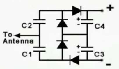
A simple diode bridge circuit for a radio wave powered electricity
generator.
Now, how close was that video done to a radio transmitter?
We
know that there are radio signals constantly traveling
through the air. If you hold up a light bulb - fluorescent or sometimes
even incandescent - near a transmitting antenna, it will light up,
usually rather dimly, to
varying degrees depending on the signal strength. No connections.
I've seen this myself when I worked in radio in the late 1970s. Low
to medium frequency radio signals seemed best, IIRC. (And I often hear
what
appears to be morse code and other LF data signals in my head when it's
quiet, without any radio equipment beyond my ears - and perhaps
fillings
in my teeth acting as diodes.)
All
very well if you live right next to a radio transmitter antenna?... But
light bulbs aren't even made to pick up radio energy. Their "antennas"
are laughable. (or did the person holding the bulb have to hold a
bulb terminal? I can't remember.) How far away could they work if they
had
good antennas
to pick up the transmissions?
There are natural radio waves as well as
man-made, mostly at very low frequencies. Perhaps most of us simply
haven't suspected that they may contain
useful amounts of energy. I looked this up on line. From the
graphs I saw nanoteslas of field strength, and nanowatts
per
square meter of energy. This isn't very auspicious for getting
great gobs of power, but perhaps it was worth trying out. Since the
anticipated frequencies are very low, one suspects the longer the
antenna the better. Perhaps some tuned distance from the ground would
be ideal.
Here's some info I found at a web site about natural radio signals:
Natural Radio Lab [a web site]
Natural Radio is the VLF radio emissions that originate
terrestrially
from lightning and within the earth's magnetosphere through interaction
with the Sun. These radio signals, sferics, tweeks, whistlers, chorus
and others, occur within the range of human hearing, and can be heard
with simple receivers as described on this site.
Natural Radio Lab also looks at Space Weather and the related
solar activity that influences it such as sunspots, solar flares and
Coronal Mass Ejections.
Please explore this site. I hope you go beyond reading what's
here and actually go out and take the opportunity to hear whistlers or
the enchanting sounds of the dawn chorus.
Mark Karney, N9JWF
Webmaster
I found the "Tesla's secret"
website with the diode circuit info here:
http://www.magnetmotorz.net/hojo-motor
Soon I discovered an identical website:
http://www.energybytesla.com/
Then I found what may be the real source of the circuit,
invented this
year in April by Dennis Siegel,
although neither the article nor Siegel's own web pages describe the
circuit:
http://www.naturalnews.com/039814_radio_waves_batteries_charging_device.html
http://dennissiegel.de/electromagnetic-harvester/
I noticed that Siegel's site shows him next to power
stations and various
electrical things... so he seems to be mostly harvesting 50 or 60 Hz
power line energy - to charge small batteries. That's not exactly the
sort of abundant 'green energy' or 'radio waves' I was thinking of, tho
it's not
limited to
harvesting from power lines.
Given that the name of the book is "Energy by Tesla", the
first of the identical websites was probably copied from the second,
where I
found it looking for magnet motor designs. Now... what has the 47$
book got that the circuit on the web page doesn't... if anything? Does
it
expand on what the nuenergy.org site (below) has?
The question is, what frequency should
the antenna and capacitive components be tuned for... or is tuning
something to be considered? Capturing 60Hz power fields would imply a
long antenna (or one next to a power wire) and
very large capacitors. I have some 2.2uF non-polar
capacitors for C1 and C2 - non-polar doesn't get much larger than that.
The
site mentions germanium diodes, which are rare these days but have the
lowest forward voltage drop... best to have if the voltages expected
are low. (not to be confused with geranium diodes, which have big red
flowers.)
I decided to try out the circuit. If that yielded
interesting
results, I might order the book they offer and see if it's really
practical to build something to generate more useful amounts of energy.
(This was before discovering the CMBR stuff, below.)
I talked to ham radio buff Ian Soutar. He said such
devices used to work better when there were higher output radio
stations around. Evidently some used to be up to 250KW. I remember 50KW
as being the maximum allowed. Now apparently it's something like 5KW.
Ian said that farmers living under high voltage power
lines would
make special transformers to harvest electricity from the magnetic
fields, and power their whole barn (eg, lights and milking equipment)
with them. This is certainly more than just powering a cell phone
charger! Finally a specially equipped helicopter flew over all the
power lines searching for magnetic field anomalies at barns, and all
the farmers who had this equipment were fined for stealing power, even
tho they had made no physical connections to the power lines.
He also said calculations for DC ionic energy showed
absurdly low powers for very large investments. However, this was
probably for building solid plate structures sticking up from the
ground, rather than for vast fields of coarse mesh chicken wire hung
from high altitude cables strung between hills or skyscrapers. (Maybe
even up where lightning originates.) The reason coarse mesh chicken
wire should work as well as solid plate is that electron deficient
charged ions will veer to strike the electron rich ground (wires) from
anywhere
nearby.
This effect is strikingly illustrated on Saturn's moon
Iapetus. Just 1440Km diameter, Iapetus orbits rather distant to Saturn,
so
it (like Jupiter's furthest moon Callisto (~4800-4840Km), which is
about the same size as Mercury)
hasn't been tidally churned to sink the good soil into the interior and
leave glare ice on the surface (like, eg, Europa, Dione,
Rhea...).
Saturn's magnetic field drags ionized particles with it, creating a
deadly ionizing radiation that strikes the rear ('East') hemisphere of
all its moons from behind. Iapetus, with no sort of atmosphere or
magnetic
field, has no protection from this. However, the charged ions
unerringly veer like lightning to strike high ground, leaving deeper
crater floors and crevasses free of radiation.
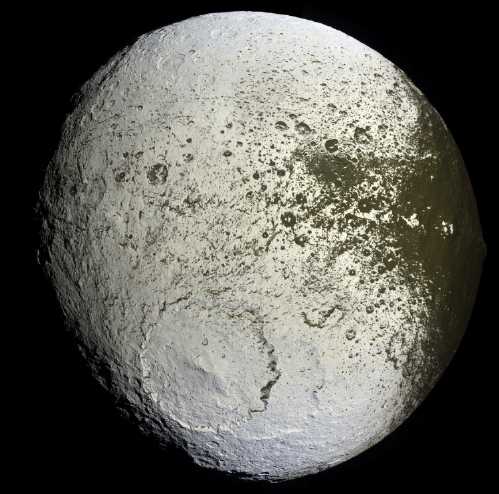
Ion irradiated rear face of Iapetus. The edge of the dark, radiation
free front face is seen at the right.
The dark vegetation can only grow in radiation free
areas: deep crater floors, crevasses, near steep walls and under ice
extrusions.
(Also it's evidently too cold toward the poles and on polar facing
slopes
- this vegetation would be a migrant from Ganymede or Callisto, much
closer to the sun.)
It seems remarkable that vegetation of any sort might grow on cold,
airless worlds, but it's the only logical
conclusion that appears to explain various science findings about the
dark surfaces such as the spectrographic data
(eg, "polycyclic aromatic hydrocarbons" - definitely stuff of life),
the diurnal temperature
profile indicating a "very fluffy" surface
'that's penetrated by sunlight', a landscape which is 'rapidly
resurfaced after meteor strikes', plus the
striking correspondence of the dark surfaces to the seemingly
non-irradiated areas in the images.
Radio/powerline field harvesting circuit: Slim Pickings
On the 15th or
16th I put together the circuit with common 1N4148 silicon
small signal diodes, 2.2uF non-polar capacitors on the input and 100uF
capacitors on
the output. I added a 15 volt zener diode in case the output voltage
actually got that high. I soldered on 3 aligator clip leeds for
"antenna", "+" and "-" connections.
I clipped on a 10' wire for an antenna, grounded the board
at
my lab
power
supply, and clipped a meter to the output. It read 1/2 a volt and was
very
gradually rising. When it hit a volt after a couple of minutes I left
the room. When I came back it was 1.5 volts... and falling. Whatever
had been imparting energy to it seemed to have shut off. It fell to
about 1 volt and stayed.
Then I took it over to Ian Soutar's 40 meter dipole
antenna. Ian said his back yard was very quiet radio interference wise,
which made it a good place to make ham radio calls from. Results at
best showed similar voltage increases with time,
and other
things we tried were worse. In a park
away from power lines with a long extension cord for an antenna, not
much seemed to happen at all. (But I'm not
sure I got a good ground.) Ian did say that it definitely needed to
have germanium diodes with their low .2-.3v forward drop instead of
silicon at
.6-.7v, since signal levels were bound to be very low.
I went to buy some and was told that the forward voltage
drop wasn't so low. I bought some 1N5817 schottky diodes instead, which
are about .35v forward drop at low currents. It
didn't work worth beans with those. It got up to about 2-1/2mV instead
of 1.5 volts. My
theory is that the 1N4148 s, being fast, small signal diodes, have
lower leakage so they don't bleed off the
accumulating voltage. Even the tiny voltage on the Schottkys dropped
off quickly when the antenna was disconnected, indicating leakage
current.
It didn't seem at all promising, but not to leave any
stones
unturned I went back the next day (17th) and got the 1N34A germanium
diodes. (Seeing just two digits instead of four after the "1N" ("1"
semiconductor junction = diode)
reminds one that
these harken back to the very first germanium semiconductors of the
1950s. Silicon came later.)
On the 20th I finally soldered them on. The voltage
proceeded to
drift negative to tens of millivolts. It didn't seem to care
whether
the antenna was connected. Ugh! I started to wonder if even the
original results really meant anything.
To find out I unsoldered the 1N37A s and put the 1N4148 s
back on.
Sure enough, when the antenna was connected the voltage began rising
steadily in the proper direction, millivolt by millivolt, to over 1/2 a
volt. With the antenna disconnected the voltage started dropping faster
than it had been rising. The original 1N4148 s that I chose because I
had them at the time, were the best of any I tried, and indeed the only
ones that worked at all. But it looked like it would take a coon's age
just to charge a cellphone, if I could get it to work at all. It might
work with the antenna right next to something drawing a lot of AC power.
As a last experiment I took off the 100uF polarized
capacitors and
replaced them with two more of the low leakage ceramic 2.2uF ones. I
also removed the 15v zener diode since the voltage never got very high.
The
voltages changed much more rapidly with the smaller capacitance and
attained higher
values with the low leakage. It soon passed a volt and went up to about
1.2v. Setting the
meter to milliamps showed .000mA short circuit current - not even a
microamp. Ten in series with ten antennas would have supplied 12 volts
at some infinitesimal current - or maybe 6 volts at a higher
infinitesimal current.
In the meantime I had started finding other versions of
what Tesla had done on 'nuenergy.org' website, and then equating vague
undefined terms like "space energy" and "zero point energy" with the
"cosmic
microwave background radiation" ("CMBR") known to astronomy.
nuenergy.org got me started thinking
about the Tesla and Markovitch energy converters. I abandoned the
apparently fickle project of harvesting
powerline and radio fields with an untuned circuit to obtain minute
amounts of energy. Seeing
the voltages rise on the meter illustrates capture of invisible energy
out
of the air -- but to get real energy harvesting, it would be better to
tap the wavelength where the bulk of the natural radiant energy of the
universe
really is, with a circuit tuned to take real advantage of it!
Cosmic Microwave Background Energy ("CMBR" or "CMB") to
Electricity Harvester/Collector/Converter
There seemed to be a large discrepancy between the circuit
and
what Tesla was doing. According to the site, Tesla's thesis was that
the Earth has a negative
charge compared to the ions coming from the sun, or from atmospheric
atoms ionized
by the sun. This DC charge causes lightning. What seems less clear is
whether this force can be
harnessed with nothing more than a plate on a tall pole to charge with
this
ionic energy. Tesla said the current is 'feeble', but that the voltage
builds up and up until it arcs across the capacitor plates.
In his circuits he mentions a coil and an oscillator. This
didn't make much sense: one
doesn't usually use coils with DC circuits. It's commonly said that
Tesla's power generator was 'very successful', but if current is
'feeble' and it takes considerable time to build up the voltage, that's
not an indication he was getting very much power. Evidently many people
since Tesla have done some calculations and decided that harvesting
atmospheric ion energy wouldn't be worthwhile: building something large
enough to harvest useful energy would cost far more than any returns
obtained.
But would it need a solid
structure? A very large wire mesh strung on a cable between two
mountains might provide worthwhile DC energy. For a relatively low
cost, that would put a very large receiving "plate" up far away from
the ground, where the charge is greater. It would probably be beyond
the scope of any sort of home project, but perhaps an experiment using
a wire mesh hanging from a skiing chair lift cable in the off season
might give an indication of the potential of the idea.
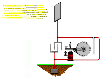
Tesla's(?) idea: capture energy from the high voltage positive charge
in
the air.
But that idea doesn't explain some of the circuits.
Tesla said (among other things):
From the electric Potential that exists between the elevated plate
(plus) and the ground (minus), energy builds up in the capacitor, and,
after “a suitable time interval,” the accumulated energy will “manifest
itself in a powerful discharge” that can do work. The capacitor, says
Tesla, should be “of considerable electrostatic capacity,” and its
dielectric made of “the best quality mica, for it has to withstand
potentials that could rupture a weaker dielectric.”
“The sun, as well as other sources of radiant energy
throw off minute
particles of matter positively electrified, which, impinging upon the
upper plate, communicate continuously an electrical charge to the same.
The opposite terminal of the condenser being connected to ground, which
may be considered as a vast reservoir of negative electricity, a feeble
current
flows
continuously into the condenser and inasmuch as the
particles are …charged to a very high potential, this charging of the
condenser may continue, as I have actually observed, almost
indefinitely, even to the point of rupturing the dielectric.”
- Nikola Tesla
But this didn't explain what the coils were for. Another web site
had quite different ideas of what Tesla
was doing:
http://www.nuenergy.org/space-energy-receiver/
"
The device in question is one of a number of energy transducers
that
converts extremely high frequency energy to a
form comparable to
alternating or direct current electricity. The process involves in all
cases, the utilizing of the instrument as a specially designed
resonating cavity. This cavity can be composed of either a number of
crystals, a series of coils, or a combination of the above. To
understand how the unit operates, it is first necessary to briefly
describe the nature of this energy source.
Research and experimentation have established that this energy is
one that pervades the known universe and is constantly flowing through
the Earth itself. It has been found to be quite dense, with enough
power to light an American city of around 50,000 persons for a year.
Because of its origins and immense power potential, this energy has
been called “vacuum,” “cosmic,” “radiant,” or “zero-point” energy. Dr.
Nikola Tesla, the discoverer of the electric age, may have used this
energy to create his most fantastic invention-the “Magnifying
Transmitter.”
"
Sometime early on,
it occurred to me
that "space energy" and such names as those quoted above, and the
"cosmic
microwave background radiation" ("CMBR" or "CMB"), were
probably - and soon I felt surely - the same thing. CMBR was doubtless
the grain of truth behind all the vague, undefined terms.
In the paragraphs
above are the clearest concepts of what is being tapped. The "research
and experimentation" have apparently uncovered the strong EHF energy
radiance, but remarkably, without identifying its wavelength or
realizing that this is the same
energy that's known as the CMBR to astronomy. Here we have Tesla and
others converting not DC ions but this EHF "Space
Energy" to some usable frequency of electrical power. This explained
the use of coils
and
tuned circuits. But part of the confusion is probably owing to Tesla
himself not knowing exactly what he was doing: science wasn't as
advanced as today and it's said Tesla didn't even
believe in the new idea of subatomic particles at that time -
notwithstanding that he was working with them.
It was noted that the electrical currents flowed around
the outside of the wire and not in the center, the "skin effect"
consistent with very high frequency current. And it's noted that the
frequency is so high that the energy only appears like 'normal'
electricity in
some respects, and unlike it in others. This sounds like an energy that
needs to be 'stepped down' in frequency and form to turn it into
something usable and essentially recognizable.
Power from a 'space energy collector' device by Markovitch
in the 1970 s
was reputed to have produced 180V and 3A. Presuming that's both at the
same time,
it's 560 watts. Later I heard of the 50KW machine of the 1930 s. This
sort of power sounds like something more
more able to generate the story of Tesla's success that's been passed
down through the decades. A "resonating cavity" sounds a lot like a
"waveguide" as in a klystron or magnetron tube for radar and microwave
frequencies.
It
takes knowledge and
expertise to design and to build the requisite circuits (as well as
some luck if your understanding of what you're doing is vague), which
explains
why Tesla's work hasn't more often been duplicated. Nevertheless, the
nuenergy.org site provides a description of what needs to be made.
There are a couple of pictures. Perhaps together with the text they're
sufficient.
Back to the CMBR... First, note
that so-called "microwaves" are really "centiwaves". The ones used in
radars and
"microwave" ovens are several centimeters wavelength. Next, from
Wikipedia article "Cosmic
Microwave
Background":
"The spectral radiance
dEν/dν
peaks at 160.2 GHz, in the microwave range of frequencies.
(Alternatively if spectral radiance is defined as
dEλ/dλ then the peak wavelength is 1.063 mm.)" [the zero is
surely a mistake and it's 1.863 or 1.63mm.]
According to some
definitions, that's above microwave frequencies - between them and the
far infra-red. And, most interestingly for free
energy: "Most of the radiation energy in the
universe is in
the cosmic microwave background."
Here we have apparently a very substantial energy that
pervades the known universe.
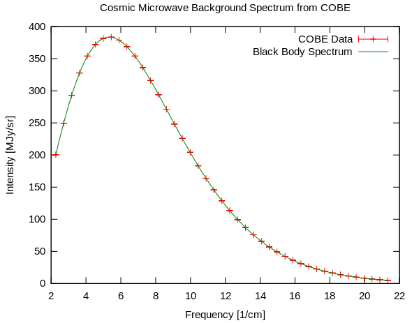
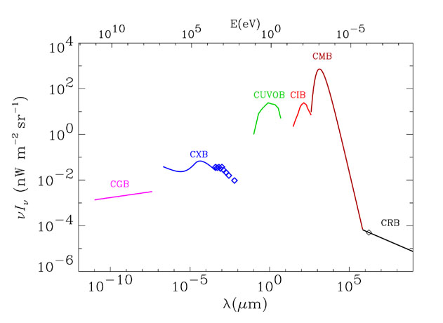
The graph shows the wavelength of maximum intensity as
just under 1/5cm or 2mm. (1.863mm would probably agree with the 160GHz
figure.)
CMB appears to be much more powerful (50x?) than sunlight.
http://www.cv.nrao.edu/course/astr534/Introradastro.html
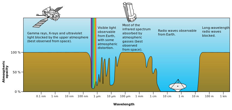
The
atmospheric absorption of energy at various spectra seemed interesting.
Radio wave
energy is a wide band that can come straight in from space almost
unaffected
by the atmosphere. However, looking at the chart above it didn't appear
to
include the 1 to 5 mm
energy area of the cosmic microwave background. That seemed to more or
less rule out harvesting cosmic microwave radiation... which seemed
puzzling if it had
been done. (The caption did say it was a "rough plot", but it also
claimed absorption "above 20GHz".) So I searched and found another
graph from another source,
below.
The
difference was night and day! This one showed atmospheric
transparency in the critical area of high energy, from about 2mm
to 8 or 9mm. (1 cm = 10^8
ångstroms.)
Really
it
only
indicates
for
certain
that
"less
than
half"
the
CMBR
energy is blocked at sea level, so both graphs may be somewhat
misleading. Even according to the first graph it's not entirely
blocked. But going by the second one, at least over half of the CMBR
energy reaches sea level, and with the steep sides, it seems more
likely that the bulk of it gets through. This was later confirmed by a
third, more detailed, chart, which shows practically all the energy at
160GHz
reaching the ground, albeit at a high desert elevation.
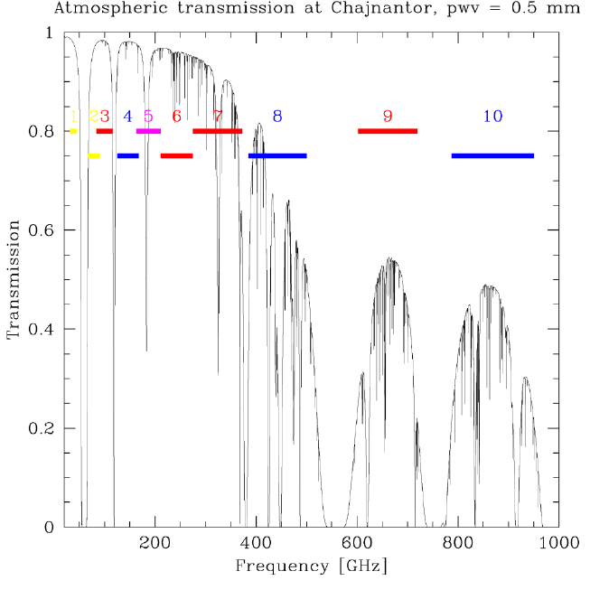
http://www.cv.nrao.edu/course/astr534/Introradastro.html
So it seems that
the
microwave background energy does reach Earth's surface, and thus it
should be possible to capture it with a working system tuned to
somewhere between a 1.4 to 2.5 mm wavelength, and that this is 'most of
the radiation energy in
the universe'. It could be harvested anywhere, including in space to
power spacecraft, replacing solar power and RTEGs. It would appear from
more than one source that CMBR is the free energy 'big fish', known yet
unknown for a century!
What's needed, then, is an assembly - parts of it can
hardly be called a circuit - to capture this energy. The principles of
working with wavelengths that are very short in comparison to the
components (at least on centimeters scale) are reasonably well
understood, and the striplines and
resonant lines ideas will be noticed in common in the designs that
follow. From Wikipedia ("Microwaves"):
"Open-wire and coaxial transmission lines used at lower
frequencies are replaced by waveguides
and stripline,
and
lumped-element
tuned
circuits
are
replaced
by
cavity
resonators
or resonant lines. In turn, at even higher frequencies, where the
wavelength of the electromagnetic waves becomes small in comparison to
the size of the structures used to process them, microwave techniques
become inadequate, and the methods of optics
are used."
As I read more and
more stuff, there seemed to be some common
principles emerging - similarities between devices, with toroids or
rectangular frames having transverse 'control' wiring, close parallel
wire loops, sharp excitation pulses with solid state drivers, and so on.
It
seems that many people with dozens of designs
have managed to tap the CMBR over the years - the invisible but
'brighest' radiance in
the whole electromagnetic spectrum - without a clear understanding of
what it was they were tapping.
The CMBR's 160 GHz
is at the upper frequency limit for radio techniques, a little below
where optical techniques become more effective.
What has happened in the century and more since Tesla
first lit banks of light bulbs with power from the void? As a friend
told it (from web info): "There was a man named T. Henry
Moray back in the 30's or so who developed a "box" that could pull 50kW
continuously out of "space". His device was witnessed by many
scientists and engineers of his time, but he faced a lot of opposition
and had his equipment and lab smashed etc. If I understand anything
about it, the principle was some sort of resonant condition excited by
a natural energy vibration in the ether." (His patent was apparently
"lost" by the patent office.)
Again it seems like the typical
bitter experience of someone who had the temerity to try and lift
mankind out from the clutches of the gangster-parasites who (so far)
control our society, and to try to help us get clear of the intake hose
of their greedy 'money vacuum cleaner' of "pay
per fillup" and "pay per month" energy that's causing wars and
gradually ruining the environment. I've read of worse.
And again the "natural energy
vibration in the ether" is doubtless explained as the CMBR. 50KW is the
largest figure I've seen yet, and very promising to say the least. It
would be plenty to power an electric car. I wonder how
big the device was? Doubtless there's some figure for "[kilo]watts per
square meter" of radiance actually available. If it's comparable to
sunlight and 50 times as powerful, it would be 50 KW/sq.m since
sunlight is very close to 1.
Performance of the Markovitch "Space Energy" harvester in the late 1970
s:
"According to reports the device is supposed to have worked, with
maximum voltage of around 180V and 3 amps. Strangely both a DC and an
AC component were found in the output. There were some pretty high
powered witnesses to these experiments including scientists and
technicians."
Unfortunately the 1970 s is
a while ago now. It would be great to be able to find witnesses or
Markovitch and learn more. Some key features appear to
be a plate or globe perhaps 1/2 a meter or more in diameter and a gap
to a needle point that the energy jumps across. Then some weird
'bifilar' coils maybe with some kind of crystals. That's pretty vague
stuff to go on.
Tesla's "Bifilar Coil"
The signal travels from the outside to the center twice, with the
second loop parallel to the first.
This was said to multiply the inductance manyfold.
(I note that the
gap between the two wires is similar to
the wavelength of the CMBR rays.)
Other 'Free Energy' Devices
My present theory is that at least two
"hidden" energies are available for harvesting:
1. Nuclear (or perhaps ambient thermal) energy brought from the atomic
scale to
the mechanical scale via magnetism.
2. Cosmic Microwave Background Radiation.
Cruising through web sites looking for more info, one can
hardly avoid finding more novel ideas for harvesting "energy from the
void" and magnetic energy. At first I ignored anything that didn't look
like what Tesla had done, but I started finding some free energy
'pulsed transformers' that looked interesting, and which were also
probably 'harvesting' BMBR.
Here's a "motionless electric generator" ("MEG")
apparently patented about 2002 with a transformer that is supposed to
resonate
and have a "COP" of 5, producing 5 times as much energy as it consumes.
http://jnaudin.free.fr/meg/meg.htm
. It's supposed to be up to version
"Mark 4" now. A mark 3 was made by another person, Naudin, showing that
the design is replicable. But one suspects he got verbal instruction
from Bearden beyond what's written in the patent. Now I've run across
other units with similar themes. Again it would
appear from undefined and unexplained terms like
"Active Vacuum" that the makers, like Tesla and others, don't really
know where the energy to make them work comes from.
The
Motionless Electromagnetic Generator,
Extracting Energy from a Permanent Magnet with Energy-Replenishing from
the Active Vacuum
from Thomas E. Bearden, Ph.D. James C. Hayes, Ph.D. James L. Kenny,
Ph.D. Kenneth D. Moore, B.S. Stephen L. Patrick, B.S.
"MEG mk2" showing oscillator and coil driver components.
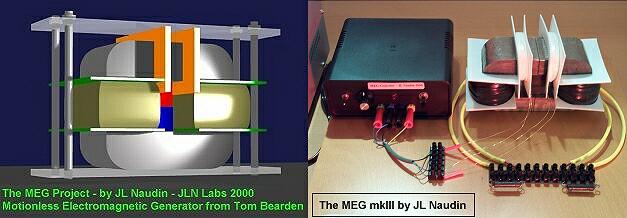 "..This one works
beautifully and produces COP=5.0..."
has said Tom Bearden
US Patent 6,362,718 :
Motionless Electromagnetic Generator
"..This one works
beautifully and produces COP=5.0..."
has said Tom Bearden
US Patent 6,362,718 :
Motionless Electromagnetic Generator
(The link on the site to
the US patent office generates an error. I've put in one that didn't.)
One wonders what has happened to these devices. It seems
they've never been mentioned in the media, and it hasn't started
replacing
the power grid in over a decade of existence.
On reading more about this device, it would appear to be a
modified way to tap the CMBR rather than a magnetic power source. A
permanent magnet may seem like an odd feature, but the magnetron, a
well known microwave tube, has one, so use of magnets is commonly
associated
with microwaves. At
first it looked like it might be the easiest unit to construct, but on
the website, cheniere.org, maker Bearden speaks of 'nanocrystalline
core
material' and says it won't work with an iron core. Turquoise Energy
Newsletters of the past show that I had no real success trying to
create such cores (although the ilmenite in sodium silicate coil
coatings improved the efficiency of the Electric Hubcap motors, and may
well
have application here).
Funding, especially for advanced techniques probably
needed to produce such cores,
is evidently what's been holding up commercial production. Naturally,
it's the
corrupt that
have nearly all the wealth, and they certainly wouldn't want to fund
something that would let people make their own electricity freely.
Perhaps the iron powder cores I have for Electric
Hubcap/Caik/Weel motors could have application? If not, the maker
(micrometals.com) does have other core material choices. But not the
sort of transformer double "C" core shapes shown.
A Simpler Pulsed Transformer Design
In my web searches I had clicked on many links, each
opening in a new window. A couple of days after investigating the above
unit, I found a window on my screen, hidden behind others, with another
'pulsed transformer' energy design. This one looked easy to make, using
air cores, and the
construction details were shown in a PDF document. An irritatingly tiny
photo of the device on the web site turned out to be in fact 1280 x 960
pixels
if downloaded, big enough to see a lot of detail. URL:
http://freetesla.blogspot.ca/2011/08/successful-tpu-ecd-replication.html
The site was in fact showing someone's working replica of
a 2007 design found in a PDF document at:
http://www.overunity.com/index.php?action=dlattach;topic=2383.0;attach=9524
There were also a number of links to videos, but none of
them worked - the videos had been removed from the Google video site.
Furthermore, a Wikipedia article on "Motionless Electromagnetic
Generator" had been removed. Even if one doesn't believe in the
possibility, the article should be there to enlighten the curious about
what it purportedly is. ...more suppression?
But the knowledge that the CMBR exists, is energetic and
omnipresent, and obviously could be harvested in some manner analogous
to a solar collector harvesting visible wavelengths,
should serve to dispel the incredulity (including by me) that so far
has surrounded such
devices.
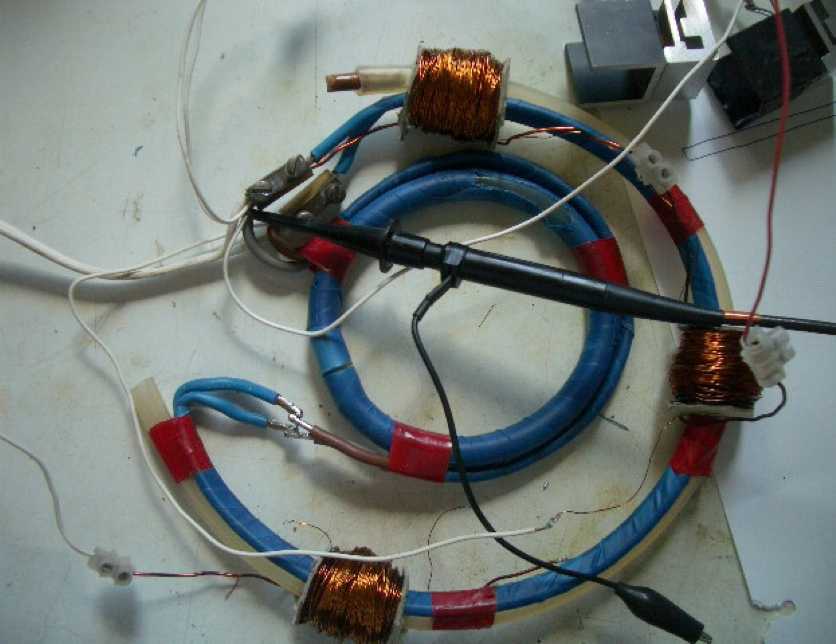
Original "TPU" Toroidal Power Unit from the PDF file
A pulsed transformer type of CMBR powered
generator -
simple to the point of being "Mickey Mouse".
(Shown with outer loop opened)
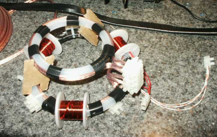
A replicated TPU. This second maker also says it works.
That the site I found was
about a
replica is very promising, since it means someone followed the original
instructions and got similar results to those claimed by the original
maker. The power output was said to be about a kilowatt,
but it would soon get too hot and quit working. (With that kind of
power going through so little wiring, I'm not surprised!) However, it
seems like a great, simple demo unit to start with!
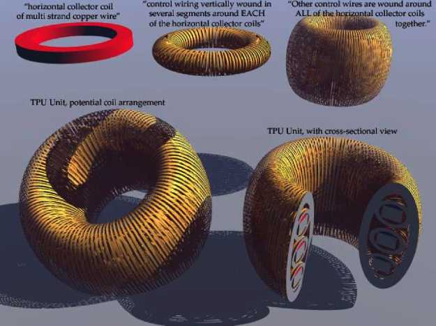
It has a "mobeus strip" coil made of 'lamp cord' - two
closely spaced parallel wires. It reminded me of Tesla's "bifilar coil"
with opposing parallel wires. It occurs to me that the distance between
two typical lampcord wires is somewhere around the CMBR wavelength of
1.8mm. That may have a lot of bearing on the tuning and pickup of the
CMBR. This runs in a double loop around two circular forms of plastic
hose. Again we see similar features between designs. The pulsed control
coils are vertical, again at 90 degrees to the horizontal collection
coil. And the vertical offset of the smaller inner collection coil
gives it a profile similar to the hemisphere-dome shape of the
collectors of the Tesla and Markovitch units.
 The operation
of the unit is quite complex. I assumed the three control
coils/transformers were energized in
sequence to create a rotating magnetic field like for a motor. In fact,
it appears that they're activated at two or three different
frequencies, which would create a complex, not to say chaotic, pattern.
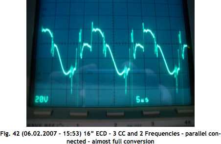
The authors show many intricate patterns of signals they viewed on the
oscilloscope. Somewhere in the correct relationship between frequencies
must be hidden the heterodyne frequency interactions to convert 160 GHz
to the
sort of frequencies transformers and electrical devices can handle.
(The frequencies used were in the x100KHz range, and could probably be
synthesized, adjusted, and held at stable values more easily with a
microcontroller than with two or three discrete oscillators.)
The operation
of the unit is quite complex. I assumed the three control
coils/transformers were energized in
sequence to create a rotating magnetic field like for a motor. In fact,
it appears that they're activated at two or three different
frequencies, which would create a complex, not to say chaotic, pattern.
The authors show many intricate patterns of signals they viewed on the
oscilloscope. Somewhere in the correct relationship between frequencies
must be hidden the heterodyne frequency interactions to convert 160 GHz
to the
sort of frequencies transformers and electrical devices can handle.
(The frequencies used were in the x100KHz range, and could probably be
synthesized, adjusted, and held at stable values more easily with a
microcontroller than with two or three discrete oscillators.)
Another feature saying some strange things are happening
was that the heatsinks for the MOSFETs, placed near each driven control
coil, got hot. But when the MOSFETs were removed from the heatsinks,
they ran cool, while the heatsinks remained hot. This would be owing to
the powerful
magnetic field that was being created (as mentioned), that they were
within. The
authors said it didn't work until the aluminum warmed up, and felt that
not only electrons but aluminum ions must be whizzing around the unit
acting as a particle accelerator. I'm not so sure.
Someone wrote in (to the 'freetesla' web site) that the
device was merely a tank circuit with coils and a capacitor, that would
have some specific resonance frequency. Of course, if that resonance
was at about 1.8mm/160GHz (or perhaps some subharmonic thereof?) it
would be tuned to CMBR energy.
I decided to try to make the unit as a 'proof of concept' demo.
This is as far as I got in September.
The electronics will be more of a challenge than the coil assembly.
Another idea of a pulsed TPU. Looks a lot more intricate to make.
Has the same idea of control coils at 90° to the single winding
collector coil.
Abandoning other electrical
generating projects?
CMBR sounds like a very worthwhile, cheap continuous
source
of electricity, so despite the challenges I'll probably
try to build one - especially having found a design with relatively
complete instructions that's been successfully replicated. If I do, I
think I should definitively abandon at
least a couple of other electricity generating projects rather than
simply add a new one to an ever growing list. In consideration of that:
Ocean wave power is a project that should be done on at
least a town-wide scale. It requires not only funding but decisions
about waterfront and foreshore land usage... by people who don't seem
to feel making such decisions has anything to do with them, or who are
averse to making decisions that could get BC or Canada into a position
of technological leadership. Apparently no likelihood of a smashing
success that would
enhance the energy future for everyone (and bring in ongoing revenue)
is worth risking having a few small failures - learning curve
experiences - for. So far it's always seemed to be like trying to row
up the
rapids to get anything happening. It would
also be a 'power grid' source for which under prevailing conditions
people would be billed monthly, probably with no benefit from it being
cheaper to produce. Especially now owing to the the good chance
that nothing would be working before the financial system
collapses,
ocean wave power seems like a good one to drop.
Geothermal power would be another example of a highly
promising community energy project, but obviously very difficult for an
individual or an unsupported small group to implement. Promising and
unpromising regions in BC and Canada to drill have been roughly mapped
out, and even at least one dud oil well, already drilled, had the
requisite boiling water temperature at the bottom. (It was filled in
again by the oil company. Like I say, the corrupt are almost alone in
having plenty of money - your money and my money - to do these things,
but they don't want people to have cheap energy.) So far the
required support hasn't been forthcoming in Canada to any group trying
to push for geothermal power. (This is a highly promising area I've
managed to not
get involved with
in any way, so there's nothing for me to drop.)
Catalytic (or "cold") fusion sounds interesting, and it
may work, but again developing it would doubtless be a major task for a
dedicated group, and then it would likely be another 'charge per KWH'
technology. (Another one for me not to take up!) I do like the idea
that traces of several elements including silver were found after the
fusion, since cheap silver would improve the performance of motors with
10% less heat in the coils than with copper.
On the other hand,
there are several forms of energy that are free after small, even
individual, capital investment in the equipment and or development. In
this category, solar, wind and woodstove thermoelectric electricity are
time and weather dependent, although in some respects complementary
weather-wise. Magnet machines and "space energy", if they can be
effectively harnessed, generate continuously, and hence are
substantially more valuable for any given 'nameplate' watts rating.
"regular" solar I already have working. I've never tried
my "sand pebbles" nanocrystalline titanium dioxide frit to cover solar
collector cover glass with little lenses and improve daily solar
collection by 20-40%, nor
have I tried out ideas I have for better dye-sensitized solar cells.
But if "CMBR converters" or
magnet machines work, solar collectors seem like good projects not to
expand further
on, especially here on the cloudy west coast. (Dropping further
expansion of
"solar" wouldn't mean dropping the
low voltage wiring system infrastructure & equipment projects. They
aren't
specifically solar related except insofar as that's what's presently
powering the system.)
The vertical axis wind turbine I now have the parts for,
and putting them together poses little theoretical challenge. It could
perhaps put out several hundred watts in a good wind... but not much
for 90% of the time. I can do a "nowhere man" and set it aside until
somebody else wants to lend me a hand with it.
The woodstove thermoelectric generator as I have wished to
implement it needs an evacuated tube radiator and a pressurized tube
radiator. The evacuated tube needs to be done for other thermoelectric
projects as well. The pressurized one should be simple enough in
principle, but implementation with the TEG module heatsink plates is
looking tricky. And it'll only put out
around 100 watts for a considerable investment in TEG modules and
heatsink & plumbing components. It might be a good one to set aside
-- and then abandon if the 'space energy' converter makes as much or
more electricity.
Since they seem so promising, even if highly challenging,
I guess that narrows it down to magnet machines and "CMBR"
harvesters, with the wind turbine when it's convenient. The rest I'll
probably drop unless I get nowhere with either of these for a
considerable period.
Electricity Storage - Turquoise Battery Project (etc.)
Main Discovery Points for September:
* Using a strip of zinc as a comparison electrode in discharge tests,
it was noted that at
no point of discharge down to 1.5 volts was the manganese
negative electrode
equal to or less
negative than the open circuit zinc electrode. There's some level of
uncertainty because the readings on the zinc electrode kept varying, by
as much as 1/4 volt, but taken at face value this means (a) that most
of the decrease in voltage during discharge is occurring in the
positive electrode (so the negative has substantially more effective
amp-hours - which is theoretically the case - and or better substance
utilization, also likely), and (b) that it should
after all be okay to discharge the cells to
1.5 volts or less: the zinc shouldn't oxidize.
I'd want to test this further and check the zinc terminal
strip for corrosion and the posode for changes over time from such big
changes in oxidation state, but if it's okay, that gives many (up to
67%)
more
amp-hours if one is willing to accept 9v from a six cell, nominally 12v
battery that charges at almost 18 volts and has over 15 open circuit
volts when fully charged. Again, a DC
to DC converter might be employed to regulate the voltage. When the
cell was accidentally run down to 1.29 volts, the negode voltage did
appear to fall to the zinc voltage, so there does appear to be a limit
somewhere not too far under 1.5 volts. It will depend on the ratio of
active substances between electrodes, but these remarks should apply if
"+" and "-" are the same volume, which gives considerably more
amp-hours of dense
negative material than lighter positive nickel hydroxide and
permanganate.
* So far, I haven't been able to get a manganese electrode in a cell at
pH 14 (in KOH) to charge and hold its
charge, even if the cell is cool, eg in a fridge. (My own electrolyte
varies from pH 7 to 12 or 13, seemingly drifting towards the upper
ranges after a while.) In pH 14, the zinc test electrode is more
negative than
the "Mn" negode under load, so only the zinc 'conductivity additive' is
charging and discharging.
An electrolyte of KCl
+ KOH
with enough KOH to raise the pH to 14 (or maybe it's just 13+) still
doesn't
work. Theoretically pH 14 won't oxidize the nickel
plating on the posode pockets as a lower pH would. If it worked okay,
Changhong batteries could probably make NiMn batteries of over 2 volts
on their existing NiFe/NiCd 'Edison cell' production line (purchased
from Varta). So far it
doesn't look like that's viable.
* The MnMn cells hold more voltage and energy longer as they age or as
they're
charged, discharged or cycled. It seems to take some weeks, but the
self discharge gradually decreases. (graph below.) If this is what
needs to be done to
get
them working, it's worth the wait for the performance. If however the
posode is disturbed, considerable self discharge returns and the
process must start again. In the one case of this so far, the self
discharge returned after I opened the cell and replaced the broken
graphite terminal sheet/strip, removing the old one and slipping a new
one into the electrode behind
the perforated graphite collector sheet.
The process has continued into October and I'm expecting
the self discharge to drop to trivial or at
least easily workable levels within maybe 3 months.
* The batteries are now effectively working, but from the amp-hours
attained, the utilization of the active substances seems very low,
perhaps only around 2 or 3 percent. Here is one more number that should
be multiplied by 10 or so before the cells will compete with lithium
ion in energy density. I don't understand why it's so low. Back in my
researches I have had batteries that have put out an amp hour or so
instead of 1/10th of one, if only at voltages below a volt. And in
fact, these ones put out far more amp-hours if run down to a volt or
less too, but that corrodes the zinc collector plates. At this
point, it might be well to try to interest a manufacturer such as
Changhong, since they may well be able to solve this problem without
further effort on my part. But perhaps in making a few more cells I'll
get better at it or figure out something.
Nickel-Manganese Alkaline Cells
It occurred to me that it might be just possible that
manganese negodes with both antimony sulfide and zirconium silicate
would hold their charge in alkaline (pH 14) electrolyte. The -1.57 volt
reaction potential would definitely stretch the limits of what's
possible. If it worked, Ni-Mn cells just might be makable by Changhong
batteries on their existing Ni-Fe/Ni-Cd assembly line, which could make
2 volt alkaline cells available quickly. Theoretical cell voltage would
be +.49v - -1.57v = 2.06v - identical cell voltage to lead-acid.
I tried it out using the case and nickel electrodes of a
Changhong NiFe cell. It seemed to take a charge, but then to lose it
again. I put it in the fridge and it seemed to hold it better, but
still lost it overnight. Furthermore, the voltage dropped below the
nickel-zinc charge voltage, so it wasn't just the manganese that
wouldn't stay charged.
So I rinsed the electrodes and changed the electrolyte,
which had been sitting in the cell and not sealed from the air for
quite some time. The Mn electrode had broken up after it was made, and
it was made up of these broken pieces. A couple of them fell out during
the rinse - not a very auspicious sign! But I hadn't tried to seal the
top, only the sides and bottom. My plan had been to not fill the liquid
to the top. I didn't see any rips. S.G. of the KOH was about 1.2. When
I put the cell back together, the voltage was 1.95 volts: evidently the
zinc was metallic, but the manganese, by and large, wasn't. The liquid
was still quite warm from mixing in the potassium hydroxide, and the Mn
wouldn't charge. With 300mA going in, it stayed just under 2 volts. I
put it in the fridge. A while later I unscrewed the filler cap assembly
and stuck a lab thermometer in the hole, so I was monitoring the
voltage and the temperature of the electrolyte - about 22°c and
1.966 volts, ~300mA.
One hour: 16° - not charging. With the charge removed, the cell
soon dropped to 1.87 volts - lower than when first filled, but
reasonable for nickel-zinc. This would be the minimum voltage to allow
during discharge - call it 1.9 volts - in order not to start corroding
the zinc current collector.
But why was it now working worse than when I'd first put
it together? It wasn't taking any sort of charge above zinc level, but
it had when first made, even at room temperature. The only thing I
could think of was that I had tightened, a little, the tie-wraps
pulling the electrodes together. But if that had caused a short, why
would it hold any voltage?
1-1/2 hours, 12 degrees, still no changes to voltage and
current. 2 hours, 11°, still nothing. Overnight, 4°, still just
nickel-zinc. What the bleep? All I'd done as far as I knew was change
old electrolyte that probably contaminated with carbonate from CO2 in
the air for a fresh batch. The devil must be in the details somewhere.
Maybe I should have hung onto the old electrolyte to see what was in it!
So far, pH 14 and Mn negatives don't seem compatible.
MnMn Too... finally holding a charge
While I worked on the NiMn-alkaline idea, I also had my
MnMn cell. I rolled out some clay to less than 1/8" thick and formed
some into a ceramic 'box' with an open top, sized to put one of my
electrodes into, as well as a couple of thin flat sheets. It was
porcelain clay ("Laguna B-Mix cone 5"), but I only fired it to cone 06
(80 minutes in my mini kiln) which made it a porous ceramic
(Earthenware). The fired
thicknesses measured about 1.5 to 3mm - not very uniform, also pretty
thin for pottery.
I hoped the fine pores would allow chlorine and
hydroxide through but block the heavier permanganate ions. I fired
these on the 5th or 6th and put the posode in the box and into the cell
on the 7th, with the liquid not quite up to the open top of the box. On
the night of the 7th-8th things didn't look very promising: the cell
held 2.16 volts or so overnight. At least it was better than 1.95. I
charged it heavily a while in the morning. The lab smelled of chlorine:
the ferric chloride if not the potassium chloride was gassing at the
high charge voltage. I then went
to do a 20 ohm load test. It
worked nicely for a few minutes, then I was interrupted by someone at
the door. I forgot about the battery for over an hour, and when I came
back it was down to 1.3 volts - oops. I put it back on a low charge and
left it.
In the evening I disconnected it and it was soon down to
2.54 volts, but then ticking off the seconds per millivolt of drop, it
looked promising. By morning, the 9th, 8 hours later, it was still at
2.38 volts. It didn't have much high voltage energy left and only put
out 40+mA into
a 50Ω load for 4 minutes before dropping to 2.0 volts.
But it was much the best charge retention so far. If it
continued to improve, if it held 2.5 volts, it could be a usable energy
storage battery. The ceramic didn't seem to have helped much the first
night. Was it improving because of charging and the various things I
had done deliberately?... something to do with the gassing off of
chlorine?... or was it because the overly heavy discharge had released
zincate ions, which then perhaps spontaneously turned into Zn(OH)2 or
ZnO and clogged the pores of the ceramic? Was the pH becoming more
alkaline if the chlorides were gassing their chlorine? It was now
rather difficult to take the top off and measure pH because the heavy
clay box didn't turn with the lid and the electrodes were getting
twisted. Perhaps further trials over a few more days before I risked
that...
That afternoon the cell seemed to be holding voltage even
better than the previous evening. Something seemed to have happened
that was now slowing the self discharge. A load test also revealed that
the internal cell resistance was higher. From 2.55v the voltages
dropped lower with a 20Ω load test (under 2.3v almost immediately) and
showed only 40mAH, but from1.85v after 21 minutes it recovered to over
2.45, and could then run a 50Ω load with good voltage. (I only ran it
for a couple of minutes - it might have gone 10 or more.)
The cell seemed to have fairly even performance over the
next weeks, capacity going up or down depending on charging conditions
and how long it sat after charging before a load test.
Self discharge/pH/permanganate trapping clues
Over the next few
days it appeared to be holding about 2.46 volts for 8 hour periods. On
the 14th it was up to 2.485. It still didn't run at over 2 volts for
very long even with just a 50 ohm load, but the periods slightly
lengthened
each day, for example hitting 7 minutes on the 13th. On the 14th
I ran it down to 1.7 volts over 40 minutes - still just 27 mAH. The
zinc strip still measured about .2 or .3 volts less negative than the
Mn negode. On the 14th-15th it held just over 2.50 volts for over 8
hours and delivered a few more mAH in the morning. In the afternoon
after charging a while, it ran 33 minutes down to 1.9 volts with a 25
ohm load. (Of course it would have considerably run longer if I had
drained it down to 1.7 or 1.5 volts.) Each few hours or a day seemed to
disclose further gradual improvement in performance.
Until on the 16th I opened it to check the pH, which I had
wanted to do for some time. It was pH 12 - excellent place. But opening
it disturbed the connections to the posode, and twisted
things around a bit. I found that high self discharge had returned,
notwithstanding that there was no apparent disturbance to the ceramic
holder. This meant it [probably] wasn't the pottery that was preventing
the self discharge, but more likely something building up over time and
changing in the surface of the electrode itself, that was 'gluing' the
permanganate into the electrode. That would probably be related to the
organic sulfate and sulfonate compounds in the 'Lemon Fresh Sunlight'
dishsoap. When that internal 'skin' is disturbed, the self discharge
comes back until it heals. As the end of the month approached, the self
discharge was down quite a bit, holding 2.50 volts for about 12-14
hours
on the 29th.
Other likely factors for gradual change and improvement
are (1) the addition of the ferric chloride, painted onto the electrode
and (2) the possibility that the nickel hydroxide and the manganese
dioxide were charging together to some compound such as nickel
manganate.
I think next time rather than the ceramic, I'll try 2
layers of the heavy watercolor paper around each electrode instead of
one, again with a piece of coarse macramé cloth in the middle.
At least that's nowhere near as thick as a ceramic wall, so the current
capacity should be a lot better. (I _should_ try this in a new cell, to
make sure the
ceramic truly isn't required.)
Date
Self Discharge Chart: approximate voltage retained after about 8 hours
sitting, during September.
Below about 2.50 volts open circuit, the cell has little retained
energy
and will rapidly drop below 2.0 volts delivering a load.
After opening and disturbing the cell on the 16th(?), the chelation
process had to partially start over again.
First readings after assembling the cell were about 1.9 volts; final
one is about 2.52
volts.
2.55+ after days instead of hours would be a lot better. It'll probably
get there.
Lower Voltages without zinc corrosion?
On the 11th I contrived to slip a thin strip of zinc down
the end of the slot for the negode terminal, so that I could measure
the manganese negode voltage with respect to a zinc negode's open
circuit voltage. To my surprise, at all times during a long discharge,
it read at a minimum about .2 volts more negative - even when the
discharge voltage was down to 1.5 volts. This would seem to mean that
the manganese negode is holding its charge throughout, and it's
mainly the plus side that's decreasing in voltage as discharge
proceeds. It must be the one holding a low value of higher voltage
amp-hours, and discharging through nickel oxyhydroxide (if that's
charging up at all) and potassium permanganate to nickel hydroxide and
manganese dioxide starting at 2.4 cell volts, then the MnO2 discharges
to Mn2O3 at
under 2 volts, then to Mn3O4 dropping to around 1.5 volts or less, and
ultimately
to Mn(OH)2 at around a volt. Disregarding the apparently pathetic
percentage utilization of the active substances (but maybe only of the
"+"?), this does actually
make sense in that the heavier negode worked out to far more
theoretical amp-hours than the posode.
This means the cell can (*should* be able to) discharge to
much lower voltages without oxidizing the zinc structural material. One
could after all consider 6 cells for a nominal 12 volt battery,
charging to 18 volts, then delivering starting around 15 volts (with a
light load) down to around 9 volts without damage if it's useful and
necessary.
A somewhat suspicious aspect, however, is rather wildly
varying readings of the zinc strip 'electrode', with readings often
swinging from .2 to as much as .4 volts more positive than the
manganese. If the actual case is anywhere in there, it's fine, but the
variations cast some doubt on the validity.
However, on the 26th I accidentally ran the cell down to
1.23 volts, forgetting about a 25 ohm load test that got left on for
about an hour and a half, and the Mn negode voltage was then about
equal to
the zinc voltage, meaning the manganese was pretty much discharged and
now the zinc was discharging. This shows that there is a lower safe
limit,
seemingly somewhere below 1.5 volts. This accidental run-down seemed to
improve cell performance a bit, perhaps by zinc ions redistributing and
making better connections with the -Mn particles. After a while however
the zinc terminal trip would oxidize away and the cell would quit
working, as with cell PP#2.
Nickel-Manganese: in KCl-KOH Cell
Before mid month I decided to try Ni-Mn in something other
than caustic KOH electrolyte, in which the Mn negode didn't seem to
hold a charge very well. Rather than make a new cell, I emptied the KOH
from the Changhong attempt, and refilled it with KCl electrolyte with
enough KOH added to bring the pH to 14. pH is a weird thing. It doesn't
take much to swing it wildly from extreme acid to extreme alkali, even
while neutral salt is the bulk of the solution. _Theoretically_ the
nickel plating wouldn't corrode off the nickel hydroxide electrode
shells. Also _theoretically_ the Mn wouldn't hold a charge any better
than in straight KOH. But
on the 13th I tried it anyway since it was simple to do. The initial
voltage was about 1.74 - nickel-zinc voltage from the zinc structural
parts of the electrode, with the manganese completely discharged.
I put it in the fridge and started charging it at 150mA.
The voltage rose slowly, but it seemed hard pressed to bring it up
above about
2.0 volts, and it soon dropped back to just over 1.9. Theoretical cell
voltage was 2.06, so it should have gone at least a little above that
on charge.
Subsequent placement of a zinc strip confirmed that the
voltage didn't stay much more negative than zinc: essentially the
manganese wasn't charging, and it soon lost any charge that it did take.
I didn't get around to making a fully homemade Ni-Mn cell
with a lower pH, having redirected my main energies around mid month
towards
studies of devices to convert free CMBR energy to electricity.
Soldered NiMH Battery Packs
Replacement Soldered Battery Pack for e-Bike.
Tarpaper replaces 'built-in' cardboard of original cells.
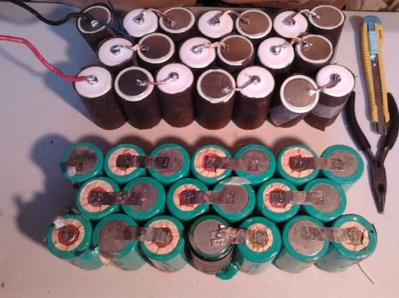
I made up a soldered NiMH D cell pack for an e-bike, and
then re-did
an earlier one for a cordless electric lawnmower. Notwithstanding my
reluctance to make soldered packs after previous experiences, nothing
else was going to fit on the bike.
I noticed the original cells had cardboard under the
plastic outer
cover. Aha! There was one part of the answer: if the pack overheated
and the covers melted, at least the cells wouldn't short circuit
against each other and cause the whole pack to go up in smoke, with the
risk of fire or injury.
I judged that the other thing I had been doing wrong was
soldering heavy
flat "bus bar" wire to connect the cells. It seemed the most
solid, but the solder joins kept
breaking with bumping and vibration under the weight of the cells. If
instead I used lighter, stranded wire, the cells could move a bit
against each other, and the wire would flex instead of putting stress
on the solder joint.
Tarpaper sheaths taped around each cell and thinner,
stranded
wire should
solve the two main problems I had been having with soldered packs!
For the bike pack I used #14 stranded wire, thinking of
the heavy
currents that would sometimes flow. But I began to realize that the
solder wicked along the wire too far, making it much less flexible. For
the lawnmower, I switched to lighter #16 wire. It soldered more quickly
so the solder didn't travel down the wires much, and everything was
much more flexible. I also used insulated wire, to make really sure no
wire could short somewhere against a case part.
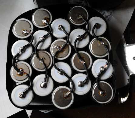
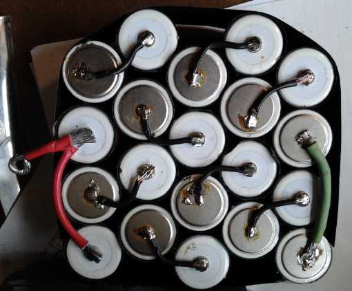
24V - 20AH cordless lawnmower battery pack (one 12V - 20AH half):
wiring with flex
should handle vibration best.
http://www.TurquoiseEnergy.com
Victoria BC