Turquoise
Energy Ltd. News #70
Victoria BC
by Craig Carmichael - December 6th, 2013
www.TurquoiseEnergy.com
= www.ElectricCaik.com
= www.ElectricHubcap.com
= www.ElectricWeel.com
Highlights:
Centrifugal Variable Torque Converter Tests (take 2? 3? 4?)
Month In Brief
(Project Summaries)
In Passing (Miscellaneous
topics, editorial comments & opinionated rants)
- Planet Titan: More exciting than Mars! - John F Kennedy
assassination 50 year anniversary
Electric Transport - Electric
Hubcap Motor Systems
* Electric Hubcap motors: Metal rotor end covers?
* Planetary Gear Centrifugal Variable Torque
Converter Transmission
Other "Green" Electric Equipment Projects
(No reports)
Electricity Generating
* Lambda Ray explorations
Electricity Storage - Turquoise
(NiMn) Battery Project etc. (no report)
No Project Reports on:
DSSC
solar cells (will probably abandon), LED Lighting, Pulsejet steel
plate cutter, CNC Gardening/Farming Machine (sigh, maybe summer 2014?),
Woodstove/Thermal Electricity Generator (will probably abandon),
Peltier & vacuum pipe heat
pumping, Ultra-efficient torque converter transmission, individual EV
battery monitor (will probably cancel).
Newsletters Index/Highlights: http://www.TurquoiseEnergy.com/news/index.html
Construction Manuals and information:
- Electric Hubcap Family Motors - Turquoise Motor Controllers -
Ersatz 'powder coating' home process for
protecting/painting metal
Products Catalog:
- Electric Hubcap 4.6KW BLDC Pancake Motor Kit
- Electric
Caik
3KW BLDC Pancake Motor Kit
- NiMH Handy Battery Sticks, 12v battery trays & Dry
Cells (cheapest NiMH
prices in Victoria BC)
- LED Light Fixtures
(Will accept BITCOIN digital currency)
...all at: http://www.TurquoiseEnergy.com/
(orders: e-mail craig@saers.com)
November in Brief
The first week and a half
of November saw more needed work around the house and yard, and various
financial/bookkeeping items unrelated to
inventive
projects.
Then, in spite of all the interesting or pressing projects
I could or should have
worked on and the coming of cold, wet weather, I had developed a strong
desire to try again to get a working torque converter transmission and
get that stationary red Sprint car into motion. At the same time, I
hoped I could do one that would also work well with a wheel mounted
Electric Hubcap system to hybridize petroleum cars with an add-on
system - per the original plan dating back to 2008. The centrifugal
torque converter became November's almost single obsession.
Variable Torque Converter Transmission
With the increasing complexity of the planetary gear
torque converter system -- the rope/pulley tension control and then the
poorly functioning clutch and flat drive belt, and finally the
flywheel... which I had put on the wrong element... I ended up, in a
couple of stages, going back to an idea dating back about four years: a
centrifugal drum system similar to a centrifugal clutch but with
fingers that would bounce off slots in the drum at intervals, the
torque being imparted with the bounces. I had made a couple that
weren't done quite right for the Tercel wheel mounted motor, then I
started building one a couple of years ago for the Sprint. Just at that
time I got excited by a magnetic converter idea that proved
impractical. After that I diverted to the slipping planetary gear idea,
which has also proven to have unexpected complications.
With the centrifugal unit, the torque goes up as the
fingers push out harder and hit the slots more frequently with
increasing motor speed. If the plastic fingers don't shred, at some
point the car should start moving. As the car accelerates, the hits
become less frequent for a given motor speed. With enough speed
(highway) and or low torques, the fingers would stay locked in the
slots and the motor would turn the output directly.
In order to give the system the maximum chance of working,
I put the chain drive with the 4 to 1 speed reduction back on, so that
only 1/4 as much torque would be needed at the drum. This reduction
would have to
be decreased to 3:1 to get the car on city streets or 2:1 or less for
the highway. This might be done along with trying out flat belt drives
again to give higher efficiency, or different size chain sprockets can
be employed.
 I made it a
"star" with five fingers (or "shoes" or "dogs") on the inner rotor on
the motor shaft, and five slots in the drum on the output shaft. The
fingers and slots would all line up at once, giving five torque pulses
distributed around the rim during each rotation -- and less by the
amount the output was already turning... assuming the car actually
moved.
I made it a
"star" with five fingers (or "shoes" or "dogs") on the inner rotor on
the motor shaft, and five slots in the drum on the output shaft. The
fingers and slots would all line up at once, giving five torque pulses
distributed around the rim during each rotation -- and less by the
amount the output was already turning... assuming the car actually
moved.
In the first test, it didn't move. Well, maybe a couple of
inches - almost downhill. Most of the energy seemed to go into making
noise and shredding bits of plastic off the fingers, flattening the
points. I decided it needed wider slots and more contact area so that
the whole face of the finger point hit the face of the slot, spreading
the load from a small area to a large one.
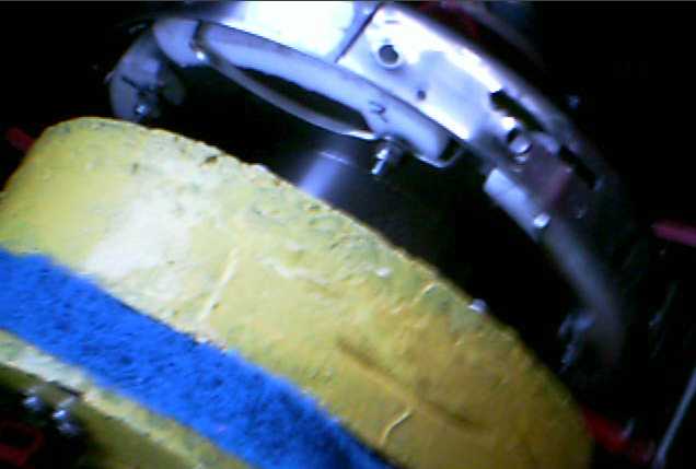
After modifying the parts and reassembling, I did a second
test on December 2nd. This time I jacked up a wheel, and at least saw
the drum (frying pan) start turning and speeding up according to how it
was supposed
to work. But the motor still ran like it had almost no load, and I
could easily stop the wheel by hand. Then, with the Sprint having a nut
at the center of each front wheel, I put a torque wrench on the wheel
and measured just around 7 or so pounds or torque, and it was still
shredding the plastic. Reverse was about the same. It didn't seem very
encouraging.
But I started looking into it and examined the parts
afterward. There were visible problems, and any part that doesn't work
right usually prevents a mechanism from performing properly. The
biggest problems were (a) that the slots were too short and (b) that
the ends of the springs were in the way. Both of these factors
prevented the 'fingertips' from going very far into the slots and
getting a good hit. I did a video of the test and dissecting
afterward: http://youtu.be/hFlztdfxHks
And perhaps changing the slots and or 'fingertips' from
45° strike angles to something perhaps more like "D" shapes would
transfer more and more of the motor speed into drum torque the deeper
the hit was as the motor turned faster, and with the right proportions
and springs ensure the motor could be appropriately loaded to produce
sufficient torque at an appropriate speed. And maybe substantially
larger "fingertips" with matching bigger slots. And if there was room
to make them 2" wide instead of 1" the forces would be more spread out.
A smooth aluminum drum would stop the chipping away at the plastic -
obviously the stainless steel pan is only for proof of concept.
The fact that I had belatedly remembered there's a way to
measure the torque at the wheels, itself seemed encouraging. At least I
can tell how much force is being developed and see how close it is to
providing enough, and compare that with previous trials to know what
works better and worse. I resolved to make the necessary changes with a
couple of part shape variations, intending to try again in December.
But the weather has turned to cold and snow, so I may move on to other
things
like lambda ray radiant energy collectors, and meanwhile simply give
some more thought
to the centrifugal torque converter.
Other Things
While I focused physical work almost exclusively on the
centrifugal torque converter, near the start of the month I had the
idea to narrate my booklet Fundamental Principles of Democratic
Government and put it up on youtube. I expect it will reach many
more people in that format and on that popular site. I started editing
it to make it more suitable for narration, typing at it occasionally
for a few days. Then my browser crashed and somehow I just didn't load
it back into the editor again. Too many things to do!
Then the clutch (the hydraulics) quit working on the
electric Mazda. I didn't get around to fixing it, and started starting
up in third gear to avoid having to shift while the car was moving. But
it's definitely an annoyance. And it's presently short one battery, and
even with that seems to be using more energy to go places, perhaps with
the cool winter weather. Somehow it's up to around 2.7 AH/mile or
worse, which at 120V is over 320 WH/Mile, up from 270-280 until
recently. Could the oil and grease in the drivetrain be stiffer or
thicker when it's cold out? I
started driving the gas Tercel more, also because I have to defog the
Mazda windshield with a hair dryer before starting.
I like the idea of the centrifugal torque converter and
not needing a
clutch or any gear shifting at all.
 On the 28th
two of
us, physicist Frank Jakovac and I, did a little web research on the
"lambda
rays", and found them denominated as "very high energy gamma rays",
with their general recognition and observation being only a decade old.
The
Chandra X-Ray Observatory satellite's map of the sky evidently puzzles
astronomers by showing the "gamma ray fog" coming from more evenly
around the sky than expected, from unknown sources. Since the "VHE
gamma rays" have distinctly different interactions to matter than
regular gamma rays - and even different conditions under which they
seem to interact - I still hold that they merit a separate name. We
don't call ultra-violet rays "VHE infra-red rays". Frank concurred that
"lambda rays" seemed like a suitable name.
On the 28th
two of
us, physicist Frank Jakovac and I, did a little web research on the
"lambda
rays", and found them denominated as "very high energy gamma rays",
with their general recognition and observation being only a decade old.
The
Chandra X-Ray Observatory satellite's map of the sky evidently puzzles
astronomers by showing the "gamma ray fog" coming from more evenly
around the sky than expected, from unknown sources. Since the "VHE
gamma rays" have distinctly different interactions to matter than
regular gamma rays - and even different conditions under which they
seem to interact - I still hold that they merit a separate name. We
don't call ultra-violet rays "VHE infra-red rays". Frank concurred that
"lambda rays" seemed like a suitable name.
The most interesting point was that unlike any other
waveband, when these powerful
photons do interact, they create "a shower of high energy particles and
antiparticles". The
"antiparticles" must be responsible for the reverse magnetic fields
noted by some of those making energy conversion devices, and of course
magnetic fields would induce electrical currents in the collector wire.
Once the lambda rays and the
processes of extracting their energy are better understood, it's likely
that better and
more effective energy conversion devices will be produced. That's when
large scale desalination of sea water may start vast desert expanses
blooming.
Perhaps even new and unanticipated applications for lambda rays will be
found.
For now, it's probably enough to understand that these
incredibly energetic "short space rays" exist and come from all
directions, and that radiant energy converters using them to produce
considerable electrical power are real and scientifically explainable,
not magical and mysterious or simply some figment of deluded peoples'
imaginations.
In Passing
(Miscellaneous topics, editorial comments & opinionated rants)
Titan
I think some great space exploration is going by virtually
unseen. The Cassini has been orbiting Saturn since 2004,
and has now flown by Titan, the
atmospheric
planet larger than Mercury that orbits Saturn, dozens of times.
Early on, in January 2005, the Cassini's Huygens probe
parachuted down onto
the surface of Titan. It sent back some crappy,
low-rez B & W pictures which, owing to their poor and colorless
quality, require
considerable visual study and comparison of the same scenes from
different altitudes of the descent to really make sense of.
The fault isn't mainly with the media - the scenes shown
are completely unexpected and alien, and the space scientists
themselves have missed the most exciting stuff. Although these images
are the meat in the sandwich of all
the spectral, chemical and other sensor data, they were carelessly
adulterated in processing, the contrast being expanded by immense and
wildly varying amounts for each image, rendering many of the scenes
virtually incomprehensible and making a correlation between various
views of the
same features in different descent images almost impossible. It was
then carelessly claimed that the adulterated images were the "raw",
unprocessed, images. Both the 'random' contrast expansion and the claim
that the results, posted to NASA/JPL and ESA web pages, are
unprocessed,
strike me as careless and unprofessional. Then, droplets of (no doubt)
methane ice on the camera lenses appears to have led to seeing
"craters" in liquid sea and hence mistaking it for solid ground. The
triply perplexing images were ignored by
the space
science community and their visual value completely discounted -
the final blunder. It was only by
very good fortune that someone sent me links to obscure web sites where
the actual raw images were archived.
The Huygens pictures do correlate with the other data to
show astonishing things, which without checking the visuals, have been
completely misinterpreted. The scientists tried to figure out what
Titan was all about with their ears, nose and touch but with their eyes
closed.


Huygens image triplet #689: * side looking camera (SLI) * Downward
~45° angle camera (MRI) * Steep angle 'telephoto' camera (HRI)
Left - the actual raw images, showing the atmospheric haze (or methane
rain) and the shallow liquid beneath the lander.
Middle - all three equally contrast enhanced by me. Contrast
enhancement brings out hidden details in the haze and under'water'
features.
Right - Every image differently contrast enhanced by JPL, often
grotesquely.
These are presented as being the "raw" images on JPL/ESA web sites
In 2009 the Saturn system's equinox in its 30 Earth years
year occurred, and Titan's 27° axial tilt north pole went from 383
hours a day darkness to 383 hours a day sunlight as the northern spring
progressed. Here is a great composite mosaic image of the arctic done
this year by Cassini CIRS and ISS instruments, perhaps with a little
help from a SAR radar imager swath or two. There are methane lakes and
various landscape features.

Titan's north pole and arctic in early summer (fall 2013 on Earth)
Ubiquitous visual image
indications that Titan is verdantly covered with vegetation are
corroborated by various spectrographic findings. The Huygens GCMS team
concluded that "complex chemistry is occurring on Titan's surface", and
Cassini examinations from space have shown more and more "the stuff of
life", apparently with no thought that there might actually be plainly
visible life.
The atmosphere is 95% nitrogen, 5% methane vapor, and perhaps 1%
hydrogen. Hydrogen, not oxygen, is apparently the active
energizing, breathing gas. (Earth C + O2 => CO2. Titan C + 2 H2
=> CH4. The oxygen/carbon dioxide cycle couldn't work as it does on
Earth because the CO2 would freeze out.)

Typical Cassini SAR Radar image of Titan's surface, mid northern
latitude.
Allowing for differences between radar and visual images, the terrain
looks like typical forest from
overhead, eg, using Google Earth, but with giant trees growing up to
2000m tall in the 1/7 gravity.
It looks unlike any other type of terrain in the solar system.
Radar dielectric constant returns are also typical of forest canopy
rather than solid ground.
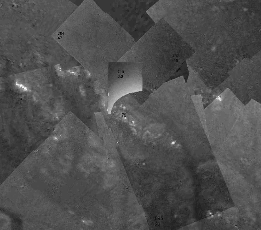
In 2006 I made a "mosaic" (this is a reduced excerpt) by piecing
together Huygens descent images from the downward looking camera.
I believe it's the most accurate one that was done, incorporating the
lowest level images that JPL left out.
(I used no partial transparencies, so anything that appears to extend
across frames actually does.
In the closest image, HRI 710, Huygens' own floodlight lights the lower
right corner so much I had to erase it.)
I concluded that Huygens landed in a shallow, duney, sea, full of
profuse aquatic vegetation
(more apparent from side looking images), on the peak of a dune ('X')
in only a few centimeters of liquid methane.
If it had landed only 30 or 40 meters north or south, it would have hit
deeper liquid and floated around.

Descent image 650-SLI.
Anyone see a giant leaf on a giant slanted stem, casting a dark shadow?
and a stem with longer, thin leaves at various angles, going across the
surface behind it?
These same features are visible from various angles and altitudes
in various images taken during the parachute descent.
(The darkening from top to bottom angles is typical of a liquid
surface, not solid.)
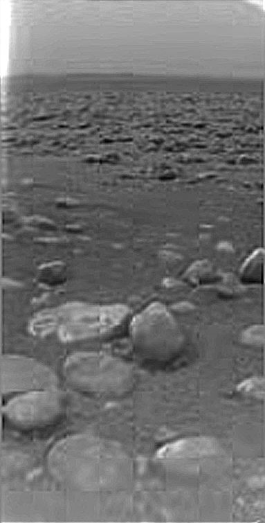
Titan from the surface after touchdown, SLI camera.
Many observers concluded "shallow liquid", which was corroborated by
the accelerometers
(registering landing impact forces), the GCMS readings ("relatively
pure liquid
methane on the surface"),
ripples seen spreading from a point in two consecutive images, and
animations of the
after
landing images apparently showing ebb and flow of liquid, as well as
Cassini T14 radio occultation returns indicating liquid hydrocarbons in
tropical areas.
Closer inspection reveals stems to many of the "rocks", some of which
are clearly elevated above the surface and casting dark shadows, and
which
were unidentified (apparently organic) material spectroscopically to
the GCMS.
In the center-left foreground are objects with 'fronds' apparently
radiating from centers.
I composed this image by blending three or four images, which provided
pixel
integration to make a sharper image showing better detail than any one
single image.
There's so much more to say
- and to speculate - about Titan! I followed the exploration closely
for some time, and I did a web page on it, Living Titan,
some years ago. Later, owing to some later realizations about a few
misconceptions I had had, I did a "Space
Update
Notes" page.
The Murder of John Fitzgerald Kennedy - 50 years back
When I noted a few issues back that journalists have
joined with energy solution inventors in being in danger from the
gangsters who run our societies for their own greedy ends, I didn't
think to mention the one group who are most of all at risk: political
leaders who would steer civilization in new directions of peace,
prosperity, equality and goodwill. It's not just the CIA, and not just
in South America, where the newly elected are asked, "I have a pile of
money for you in one pocket, and a gun in the other. Will you do what
we want?", and it's said not only to national presidents but all the
way down the line. National leaders who truly try to lead are however a
special target.
 Even as an 8
year old kid I remember how the tragedy of Kennedy's murder in November
1963 was felt by all, no less here in Canada than in the USA. It
was a coup, a crime against freedom, and a culminating event in a long
line of such
crimes.
Even as an 8
year old kid I remember how the tragedy of Kennedy's murder in November
1963 was felt by all, no less here in Canada than in the USA. It
was a coup, a crime against freedom, and a culminating event in a long
line of such
crimes.
I watched the supposed murderer Lee Harvey Oswald the next
day, who was - somehow -
interviewed on TV on the news while in custody, saying something like
(as
best I can remember it), "The president has been killed. This is a
tragedy. Everybody stay calm; the facts will come out." Greg Hunter
of USAwatchdog.com, then 7, was also watching and said this month he
remembers him saying
"I'm a patsy." (I don't remember that statement - probably I
didn't know what a "patsy" was. That may be why I remember the other
part. If he said more I don't remember it.) It was certain to both
of us kids from his evident sincerity, demeanor and his words that he
was innocent. Oswald was shot by Jack Ruby within a day to shut him up,
and I have never seen that interview come to light again. I suppose
that the tapes were soon seized and destroyed. The facts didn't come
out.
What puzzles me the most is that what actually happened is
evidently still a mystery to most people. A mafia boss whose name I
forget wrote his memoirs, long after the event but quite a long time
ago now, in which he told that Kennedy's murder was effected by "a
mafia cell" from Florida. There used to be a common type of storm sewer
drain that had not only a flat grill, but had bars going up the curb to
the sidewalk and a metal top that replaced a piece of the cement curb.
These were used in Edmonton where I lived as well. They would have made
an
admirable hidden sniper hideout even in the middle of a crowd, and he
said Kennedy was shot through the sewer grate from beneath the grassy
knoll - where so many witnesses said they had heard the shots coming
from. The
murderers then made their way off through the storm sewers with no one
the wiser.
This had the ring of truth to it to me, being the only
explanation ever offered that fits the known facts, which it does
perfectly.
Furthermore, again many years after the event, an
informant in a jail got the confession of another mafia leader who
admitted to the murder and said he'd do it again. After going to all
the trouble of getting the informant in there and getting the guy to
confide in him, nothing was done with this information and the inmate
was not questioned about it.
I saw these things on TV, yet it seems as if I was the
only one watching, as even later documentaries made no reference to
them,
and still dwelt on the "mysteries" surrounding the actual killing. Many
still conclude Oswald was a lone gunman regardless of the seeming
impossibility of a shot from the rear entering the front and
splattering Kennedy's brains out
the back of his head (among other problems with the scenario).
I won't go into all the intrigues and backroom scene
things that were going on or speculated to be factors. I think the
satirical Onion
got it right in their cartoon book Our Dumb Century (1900-1999),
in
a
"newspaper headline" reading something close to: "Kennedy
Killed by Mafia, CIA, FBI, Unions, Castro, Republicans, Military".
He preached and promoted liberty and freedom, and that didn't fit in
with anybody's
well developed schemes of manipulating and controlling the public to
their own self-seeking ends.
Kennedy left behind some brilliant and inspiring speeches
such as his presidential inaugural address, his Berlin address, his "We
choose to go to the moon" speech, and a speech to the newspapers guild
in which he warned of dark cabals seeking to destroy freedom,
among others, which are well worth listening to.
Electric
Hubcap Motor Systems - Electric Transport
Electric Hubcap Motor Construction: metal rotor end covers?
As I worked on the torque converter, I was looking at the
motor. I had switched from steel to molded polypropylene-epoxy motor
cases because of the serious magnetic drag from the steel. However,
there's no appreciable magnetic flux at the back end of the rotor. With
the design now having a rotor end cover plate that doesn't extend
around the rotor, it occurred to me that that end plate could now be
metal with no effect on performance. 1/8" or 3/16" steel might be ideal
- if heavier than the lightweight PP-epoxy. Or maybe 1/4" to 3/8"
aluminum.
And if that metal end were cut by, eg, abrasive waterjet,
it could be cut with mounting tabs sticking out, as well as the bearing
cup
sized center hole and all desired mounting, bolt and ventilation holes.
That would be an improvement over the existing design where a mounting
flange is an add-on "afterthought", and some of the long bolts holding
the motor together have to be used to attach it with.
And one less big ring piece to mold would move that much
in-house labour to being a custom ordered part, done by automation. If
that was too costly or slow, aluminum could be cut on the band saw,
albeit the result wouldn't be as beautiful and perfect.
Ultra-efficient
planetary gear torque converter
centrifugal torque converter
transmission:
Back to a Previous theory of operation...
Owing to being unable to get the flat drive belt not to
slip without what might be major work, I put the chain drive back on
and removed the clutch parts. Anyway the chain had the somewhat dubious
advantage of being 4 to 1 reduction, which could allow a marginally
performing torque converter to move the car. For the street it would
need a lower ratio, or the motor
would over-rev
at street speeds. (city about 3
to 1 or less; highway under 2 to 1)
And with the realization of my flawed theory of operation
in putting
the flywheel on the slipping gear, I had the choice of trying to move
it to the motor shaft, which would mean making and
putting in a longer shaft... or trying something else entirely.
Fickle as I am, I took the last option. I decided to try
the idea of a sort of centrifugal clutch with clockwork fingers meshing
with the slots of a slotted drum. This I had started making in 2011 in
a slightly different form (after various related attempts in 2009-10 on
the Tercel wheel mounted motor), but then I diverted to the magnetic
idea,
which seemed exciting at the time but proved rather impractical.
The theory of operation is that the fingers spring out
when the motor reaches some given RPM, much like a centrifugal clutch.
But instead of just rubbing on the inside rim of the drum, they
transverse hit slots in it and bounce off, back towards the center.
This imparts motive energy to the drum, a 45° angle impact
providing an optimum force vector.
Looked at another way, the fingers are little hammers and
the drum a big nail. Each hit tries to pound the drum around a little
bit farther around a circle. Since we don't want the motor to come to a
sudden stop, the blows are glancing and the hammer bounces off
"sideways" - actually, back toward the center. According to mechanical
clock makers, 45° is the best angle.
Here we should differentiate between the effectiveness
and the efficiency of the energy transfer during each hit. If
the entire energy of the motor was effectively transferred to the drum
by a square hit, the motor would be virtually stopped, indeed would
bounce back, as a hammer with a nail. So we want the lower
effectiveness of a glancing blow with the sideways bounce of the
fingers, allowing the moderately loaded motor to build up speed and
strike many energetic high
speed blows rapidly. Energy of course is proportional to the square of
the speed. The efficiency of the energy transfer depends on
many factors of friction and loss, but the slippery plastic has little
friction and is free to bounce around without causing much lost energy.
So notwithstanding all the rapid flappings it should still be an "ultra
efficient" torque converter. This is in contrast with a 'simple'
centrifugal clutch wherein the friction of the shoes on the drum
generates a lot of heat with poor efficiency.
In the first idea, again this could unit have gone,
perhaps optimally, on the
motor shaft, but that would require all sorts of changes to the
existing Sprint design. So once again, I decided to put it on the
slipping gear.
If the
output gear turned the same direction as the slipping gear, the drum
would more optimally have gone on the output. But they turn opposite
directions. I
mounted the drum to the frame, stationary. The amount of slip of the
gear would
depend on the torque required, slipping least when least torque was
required and most when the most was needed. I was somewhat nervous that
this didn't seem to accomplish
anything really new and untried. It was pretty similar to the rope,
which only seemed to work once the car was moving, and it might be one
more failure.
Then I thought it out again. Each time the slipping gear
stopped or slowed suddenly as
the fingers hit the slots, it would provide a pulse of torque that
should (I hope) transfer to the
output. That was something different from the steady drag of the
tension rope. Now it sounded at least somewhat promising: the pulse
effect might make it work with the vehicle stopped and get it moving -
replacing the pulley tension rope and eliminating the clutch.
On the 10th, I took
one of the weight
rings off intending to use the other as a fat plate to mount the
bolt-axles of the plastic centrifugal "fingers". Then, in order to
improve the start-stop effect, I decided to take the other flywheel
piece off too, and to use just the rather lightweight V-belt
pulley as the mounting plate for the fingers. Since it was smaller
diameter (10" vs 11"), that meant there would be more room for the
fingers between the spinning disk and the 12" diameter drum, and a
different finger shape. I hadn't made the fingers yet, so little
time was lost. A negative aspect of using the "V" of the pulley to put
the axles across was that I'd have to cut and chisel the axle-base area
of each plastic finger to fit into the "V". (image, left) But the 10"
pulley was
carefully fitted to the planet gear assembly and it would be a lot of
work to replace it with an improved part.
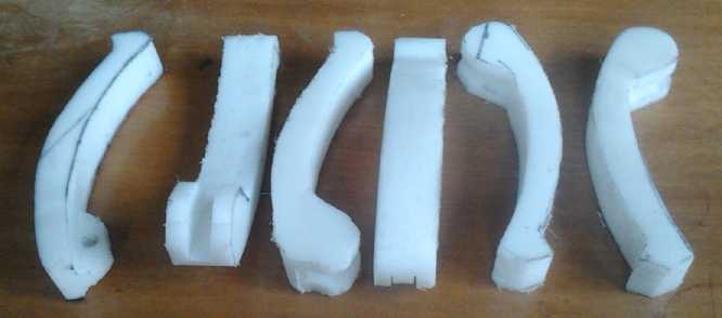 I made a
pattern on paper for the fingers, then cut it out
and traced the outline onto a piece of 1" thick UHMW polyethylene. I
made one on the 12th. Its pivot had to fit into the "V" of the V-belt
pulley, and a 1/4" bolt went through the rim of the pulley for its
axle. After much trimming, the fit seemed satisfactory.
I made a
pattern on paper for the fingers, then cut it out
and traced the outline onto a piece of 1" thick UHMW polyethylene. I
made one on the 12th. Its pivot had to fit into the "V" of the V-belt
pulley, and a 1/4" bolt went through the rim of the pulley for its
axle. After much trimming, the fit seemed satisfactory.
I had no time on the 13th. I cut 5 more fingers from the
rather small piece of plastic on the 14th, with just a few small scraps
left over. One was a spare as I had decided to make a five finger
layout with five slots in the drum. If that didn't have enough action,
I could increase the slots to 10 or 20 still lining up 5 at a time with
the 5 fingers.
But thinking back to one design I tried on the Tercel
wheel quite a while ago, I consider that it failed because its 25 "V"
links - 25 continuous 45° "VVVVVV" shapes around the rim of the
drum - had too
much coupling to the five inertial oscillator-fingers: the motor -
visibly - couldn't build up speed and hence had not much inertial
force. If it had had only 5 "V"s around the rim, it should have picked
up enough speed to give five times the energy per "hit", one strong
pulse instead of almost continual weak ones, perhaps enough push to get
the car moving. I'm not sure why I didn't think of that at the time and
try it out.
As I continued to consider this overnight, I realized that
the 6029r disk brake rotors I had one-time used for motor rotors and
stators
would make a perfect mounting plate for the fingers. The center fits an
SDS bushing to mount them on the motor shaft, and the offset center
would project the rotor about the right distance from the motor into
the
transmission box and into the drum. Then, the drum could be bolted onto
one of the "new"
flat magnet rotor plates which could mount on another SDS to the chain
sprocket shaft. And I had the five fingers just cut but not yet carved
out to fit the V pulley, the 'spare' proving fortuitous.
This 'new' design started to look pretty straightforward
to build and by the 15th - in spite of a few misgivings - I decided
it was after all worth changing everything and trying it out,
eliminating the planetary gear. In addition to what seemed like a
better design, the chain drive with the 4 to 1 reduction plus the
somewhat smaller (12") wheels on the Sprint, would give it perhaps 5
times the leverage it had directly driving the Tercel wheel, so 1/5th
of the torque would be needed. Optimized
(if necessary) and with a 3 to 1 reduction it should do over 60Km/Hr,
sufficient speed for city driving. If it could do it, 2 to 1 or less
would allow highway speeds. All automatic - no clutch or gearshift. IF
it worked! I've certainly tried enough things that haven't!
And if it worked well enough to use without a speed
reduction following, it would go very well on an Electric Hubcap car
wheel system, adding only a couple of inches width to the motor.
After it was all working on the Sprint - assuming it did -
I could print
a pulley of appropriate size for whatever reduction seemed good, and
try the more efficient flat drive belts again. (My new plan for making
flat belts: use polypropylene (or other material) strapping and make it
long enough for plenty of overlap. Sew, melt or otherwise seal the seam
along its entire overlapping length so it won't break or otherwise come
apart. Spray the belt
with urethane for better grip(?))
 I got the five
fingers mounted on the rotor on the 16th,
and cut the slots in the drum on the 17th. When I tried to ream the
edges of the cuts with a knife, and then a chisel, it finally dawned on
me that my "aluminum" frying pan with all the holes from various torque
converter attempts wasn't just some specially tough alloy: it was
stainless steel. A teflon coated stainless steel pan is a new one on
me! (No wonder it's stood up so well to abuse in several prototypes.)
But I
was left wondering how I was going to bevel the edges to 45°.
Filing stainless steel with a tiny flat file would take a coon's age.
I got the five
fingers mounted on the rotor on the 16th,
and cut the slots in the drum on the 17th. When I tried to ream the
edges of the cuts with a knife, and then a chisel, it finally dawned on
me that my "aluminum" frying pan with all the holes from various torque
converter attempts wasn't just some specially tough alloy: it was
stainless steel. A teflon coated stainless steel pan is a new one on
me! (No wonder it's stood up so well to abuse in several prototypes.)
But I
was left wondering how I was going to bevel the edges to 45°.
Filing stainless steel with a tiny flat file would take a coon's age.
I put one leaf spring onto one of the fingers to hold it
in until the motor hit "X" speed of engagement, hopefully a few hundred
RPM. I made it from #18 gauge nickel-brass sheet, work hardened through
the rolling mill a few times. After this one I noticed I could do them
with no extra holes in the rotor if the back end rested on the rotor
rim, and I also noticed a piece of 5/32" nickel-brass wire, left over
from making recorders (flutes) about 8 years ago. That should make
better springs than the sheet metal, but it couldn't be made to fit
around the 1/4" bolts. I decided to silver solder 1/4" washers to the
springs at the appropriate points... then realized that would anneal
the metal and cause it to lose its spring.
On the 19th I tried making
a spring with splitting the wire in half to
make the hole in the middle. But it was a lot of work. I had to
perforate it by drilling several very tiny holes to get a sharpened
cold chisel to cut through. Then when I tried to expand the slit to a
hole, it broke when it was just about there. A longer slit might have
done it, but the job was very time consuming -- and I needed 5 of them.
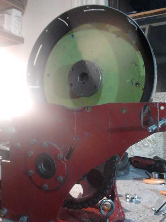
So I left the springs unfinished and mounted the drum on
the flat rotor. That at least
seemed more doable! The rotor could be mounted either inside or behind
the pan. There seemed to be not much room in the case with it outside,
so I put it inside. Somehow that took most of the day. I tried to bevel
the edges of the slots with grinding wheels in a "dremmel" tool. After
considerable grinding they still weren't what I wanted, but at least I
rounded off the edges and smoothed them.
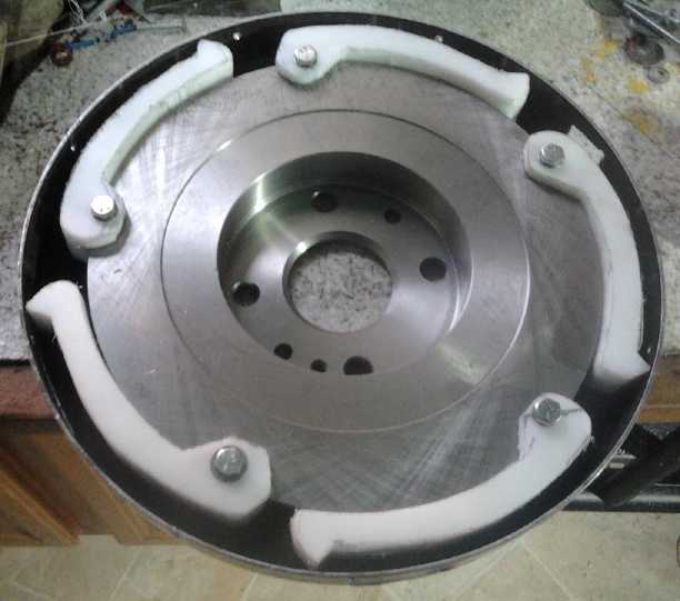
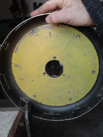
5-slotted drum rotor mounted
(One 'slot' was an existing square hole. The previously cut lengthwise
slots are irrelevant.)
In the following days, I made the springs to hold the
fingers retracted at lower RPM s. I scrapped the first sheet metal one,
which had less spring to it than the wire ones.
I used the first wire and another that I also broke a side of anyway -
they'd probably hold up through a test or two. I had everything
finished and
adjusted by the night of the 22nd.
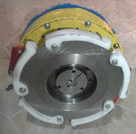
Brake disk rotor mounting the five fingers fitted on the motor.
I decided that the operative principle was probably sound,
but the implementation was lacking. It needed longer slots with more
contact
area so that the whole 45° face of each finger point would squarely
hit an ideal
45° polished face of the
slot, spreading the load across a large area. If there
had been room, the fingers could well have been made 2 or 3 inches wide
instead of 1, with 1/2" height of faces hitting each other, making 1 or
1.5 square inches of smooth surfaces striking each other.
In fact, it might be hard to fit a more suitable drum. The
walls of the frying pan were too thin to give the broad hitting surface
desired, yet a thicker wall might be either too small inside or hit the
differential on the outside. It was barely missing the differential as
it was. I couldn't shrink the drum without also making a smaller inside
rotor. I started wishing I'd picked some 9" or 9.5" disk brake rotor
instead of 10". It started to look like a pretty major rebuild.
On the morning of the 25th I got the idea to cut the ends
of each slot in the pan to make a short "H", and bend the two tabs thus
created outward to 45° to form an open bottom "V". If one edge of
the "V" hit the differential I could grind down just that area until it
missed. Unless I roughened it up with the tools in bending, it would be
smooth. That seemed easiest and had good potential for making what
seemed to be needed, so I disassembled the unit again and got the drum
off.
At first I figured
I'd open a vise to the desired "V" top
size, clamp the drum on (somehow), and hammer the flanges down over the
vise edges to about 45° perhaps hammering something like a "D"
shaped die into the space. Then on the 26th I figured out that I could
strategically C-clamp the flange part on the end of a steel bar, with a
square bar piece the size of the flange on the inside, and pull the pan
around to fold out the flange. I got started late after composing a
lengthy e-mail. It seemed to take three hands to set up each flange, I
was interrupted by a very long phone call, and then as I did the first
couple someone phoned to ask why I wasn't at the dress rehearsal for
our informal trio concert Thursday. Wow, 3PM already? Oops!
Increasingly, the days seem to go by with only small accomplishments on
green energy projects! The rehearsal, and the lunch time "concert",
went well.
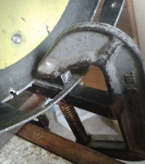
Bending out the slot face-tabs: Clamp, twist whole pan.
Bent tab edged slots
I didn't get back to the drum until the 28th after the
performance (which went okay). I finished one last tab that needed more
angle-grinder cutting the next morning, the 29th. The extended drum
tabs hit the differential even more than expected and would take more
than a little trimming to fit in. Then I considered that if I added a
link to the chain and extended the adjustment slot, the axle could move
away from the differential. The motor could adjust that high up if I
cut a piece of metal to extend the adjustment slot. I might even get
the speedometer gear and cable back in! Accomplishing this took the
rest of the good daylight, which only goes to 3 or 3:30 PM in winter.
The chain had a lot of slack with the adjustment fully extended. The
slot should really be lengthened even more, but there wasn't much more
it could go.
The chances of
getting the Sprint moving in November seemed to be receding.
As I was bending out
the 'tabs', I started thinking that
the circumferential length of the slot is actually very important. One
thinks of
centrifugal force as trying to fling things outward, but the actual
path of an object released from the rim of a rotor is a straight line
from wherever it was released. The fingertips would go outward into a
thin slot only a short distance, and farther and farther as the length
of the slot was increased. The reason the sharp tips were ground off in
the very thin slots was because only a tiny bit of plastic went into
the slot. Now the slots were 3/4" or so wide. But maybe a 1" or 1.5"
width would result in a more suitable thickness of plastic entering the
slot for the hit.
I also started out thinking it didn't matter that the tips
had been ground flat, since they would go into the wide slots all the
same. But in fact, the 1/8" or so of flatness means they'll start
moving out 1/8" farther on, effectively shrinking the 3/4"-7/8" slots,
which
I had started to consider were probably already narrower than
desirable, by 1/8". I decided I should take the fingers off and
resharpen the tips.
On the
afternoon of the 30th I replaced the chain. The original was a little
too long and I
didn't have a half-link to shorten it to a length between that and the
original too short length. (They may or may not be available.) The
other choice was to cut still longer adjustment slots, but Jim
Harrington
gave me some 'industrial' chain with links and a half link from his AGO
Environmental Electronics stock. This fit
the sprockets but wasn't compatible with the motorcycle chain. It's
said
that industrial chain won't last long in motorcycle (ie vehicle,
transport) usage, but that's a small concern at present - especially as
I may yet convert it to a flat belt before it goes on the road. Also
this chain has a lot less friction resistance to bending than the
'permanently lubricated' motorcycle chain with its rubber grommets on
each link to retain the grease.
The chain as it goes around the sprocket on the
differential is too close to the bottom 'floor' to slip in sideways, so
to get
the old chain off, after removing the master link I rolled the car
forward until it came out the end. This wasn't easy on a damp lawn, and
I almost called off the game on account of the rain getting into the
engine compartment in spite of a tarp.
When I went to put the new one on, I realized that if I simply jacked
up one
wheel I could turn it to turn the sprocket gear, with the car hood area
safely under the shed roof.
While I was putting
the chain together I also remembered that with the center nuts on the
front wheels, I could in principle jack one up and put my torque
wrench on that wheel to see how much torque was being generated. The
torque proved steady enough that the indicator needle didn't
vibrate pretty wildly back and forth, a "feature" which had led to some
serious miscalculations when I had tried making a magnetic converter in
2011.
I decided to persevere a couple more days to complete the
adjusted installation and get in another test before finishing this
newsletter. On December 1st I fitted the drum back on, removed the
fingers and sanded the tips sharp again, and made a metal piece to hold
the motor higher up than the front slot had adjustment for. It took
several tries to get this fitted out properly and to get the rotor and
drum lined up. The hard part was getting the motor in the right
distance and aimed so that the fingers lined up with the slots all the
way around. Then the height is set with the front slot adjustment.
Somehow the inner rotor was a little forward of the outer drum - not
ideal for the fingers hitting the slots evenly and simultaneously
around the drum, but owing to the large spacing between the fingers and
the drum (increased with the sanding), it at least turned freely.
Finally it was close enough to to try out. But by then the light was
fading.
On December 2nd at noon I brought out the 24V (NiMH D cells in trays)
battery, connected the cables, and gave it a try. It didn't work well.
The motor didn't seem well coupled to the load. It spun up to a
considerable speed with ease, and without making much torque at the
output. And it was much noisier than I had expected. A video with a
torque wrench on the wheel shows maybe 7 foot-pounds. The motor
connected straight onto the output shaft could have tripled that (even
with just the 24 volt supply). And again bits of plastic chipped off
the fingertips and dulled them again.
[video] http://youtu.be/hFlztdfxHks
 All in all it
was pretty discouraging. It shows how such
a torque converter might work in principle, as an example, without
actually working well enough to bother trying to propel the car. I
considered that the slots must still be too short for the fingers to
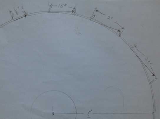
get in and get a good hit, and I drew a diagram to estimate how long
they actually should be, which was after all easy to see
geometrically.
All in all it
was pretty discouraging. It shows how such
a torque converter might work in principle, as an example, without
actually working well enough to bother trying to propel the car. I
considered that the slots must still be too short for the fingers to
get in and get a good hit, and I drew a diagram to estimate how long
they actually should be, which was after all easy to see
geometrically.
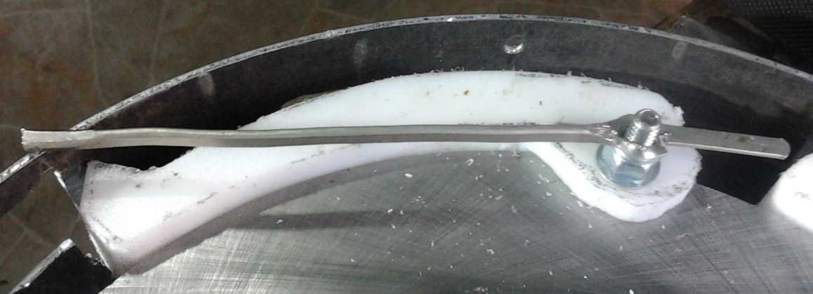
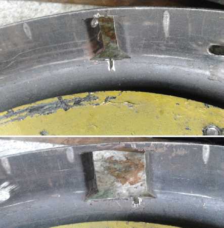
Short slot (7/8") and long slot (~1.5"). Long ones should work much
better.
Later examination showed that a separate reason the
fingers didn't go in as far as desired was that the ends of the springs
were hitting against the drum rim, preventing them from springing out
farther. And the spring ends themselves would have been hitting in the
drum slots. This metal-on-metal rubbing and hitting probably reduced
the potential
torque substantially, and also explained most of the noise.
On the evening of the 4th I took some pieces to the VEVA
electric car club meeting. Two of us discussed angles and noted that
because of the curved shape of the 'fingers', the angles to the pivot
point were quite different between forward and reverse. Owing to the
one wider slot, I hadn't tried it in reverse. On the morning of the 5th
I decided to whip everything out to the car, reassemble it and give it
a try. The results however seemed pretty much the same as in forward,
under 10 foot-pounds of force, and some of the white flakes falling
around me were plastic bits and not snow.
In spite of the
discouraging results I decided that I
would try and improve everything, correct the obvious problems, and try
again. It wasn't 5% as good
as it needs to be, but somewhere in there, in theory, is a potentially
practical converter! However, with the snow starting to fly, maybe it's
time to look at inside projects - like the lambda ray collector.
About the plastic...
Naturally people have questioned my choice of UHMW
polyethylene plastic for the centrifugal fingers that repeatedly hammer
the drum. I didn't use it without a few misgivings myself. It takes a
lot of force to move a car. As mentioned, I'm
now trying to have large faces of plastic and metal hit together
squarely
to have a low loading per unit area, but I really don't know how large
an area will be needed to have this work practically, without
permanently distorting or abrading the material. We need a unit
that doesn't quickly fail (like in the tests so far), or wear out too
rapidly to be practical. Nor do I even know for certain that it can be
made practical at all.
Another choice might be aluminum, but I found that to be
very noisy in a previous attempt at a torque converter in spite of
quite gentle contacting between parts. My ideal vision for production
at the moment is UHMW plastic fingers and a drum with thick aluminum
inserts around the rim, the spaces between the inserts forming the
slots. And two or three inch wide fingers and slots wouldn't hurt at
all.
Wikipedia has this to say, with my emphases on
its impact strength and slipperiness:
Ultra-high-molecular-weight polyethylene (UHMWPE,
UHMW) is a subset of the thermoplastic polyethylene.
<snip> It has extremely long [poly-molecular] chains, with a
molecular mass usually between 2 and 6 million u [atomic mass units].
The longer chain serves to transfer load more effectively to the
polymer backbone by strengthening intermolecular interactions. This results in a very tough material, with the highest
impact strength of any thermoplastic presently made.
UHMWPE is odorless, tasteless, and nontoxic.
It is highly resistant to corrosive chemicals except oxidizing acids;
has extremely low moisture absorption and a very low coefficient of
friction; is self-lubricating; and is highly
resistant to abrasion, in some forms being 15 times more
resistant to abrasion than carbon steel. Its coefficient of
friction is significantly lower than that of nylon and acetal,
and is comparable to that of PTFE (teflon), but UHMWPE has better
abrasion resistance than PTFE.
So that's it... this benign, inert (and I might add, clean
burning) plastic is the
best available for impact strength, and the self lubrication and low
friction make for a highly efficient transfer of energy to the drum
that won't make waste heat and need cooling like regular metal
automotive
transmission parts. When formed into fibers, UHMW's impact strength is
in fact
comparable to aramid fibers such as kevlar.
Its one drawback is that it isn't very high temperature,
but it's said to take 80 to 100°c okay. (Aramids are much better in
this regard.) Hopefully not much heat will be generated. At higher
speeds and lower torques, the fingers will probably 'lock' into the
slots and the output will turn 1 to 1 with the motor, greatly
minimizing probable heat generation.
But I confess: I used it because I had it and hoped it
would be good enough - a left over piece from making motor molds. I
thought nylon would be better, but I didn't have any and it's costly.
Only later did I look up UHMW in Wikipedia and find out its properties
were the most ideal... for a thermoplastic.
Electricity (Energy) Production
About "Lambda" Rays - the energy source for "CLBR" Radiant Energy
Harvester
On the 27th Frank, the physicist who had wandered by
earlier and calculated there wasn't much energy in the CMBR, came over
and we did an exciting exploration of waves and particles for 3 hours,
visiting quite a number of websites in quest for information.
"Cosmic rays" have very high energy. But "rays" is a
misnomer: they aren't
photons and so they don't have a place in the electromagnetic spectrum.
They are in fact charged ions, mostly protons or electrons, moving at
near the speed of light as they travel through the
interstellar medium. Energetic as they are, there are very few of them
and they wouldn't provide a viable energy source.
Cosmic ray energy from the galaxy goes up to 10^18 electron
volts per charged particle - mainly protons. Some from extra-galactic
sources have been measured at up to 10^20th eV.
We found "very high energy
gamma rays", which have only been explored in the last decade. These
are probably synonymous with "lambda rays". One website had a good
discussion. It notes energies up to 100 terra electron volts - 10 times
higher even than the frequency and energy noted previously.
Site: http://www.hap-astroparticle.org/184.php
(excerpts)
H.E.S.S. is a system of Imaging Atmospheric Cherenkov Telescopes
that investigates cosmic gamma rays in the 100 GeV to 100 TeV energy
range
(credit: H.E.S.S collaboration / ASPERA)
The last decade has witnessed the birth of a new field of astronomy
– Very High Energy (VHE) gamma ray astronomy – expanding wavelength
coverage of astronomical instruments by another 10 decades towards the
highest energy radiation. These gamma rays are produced when high
energy cosmic rays bump into interstellar gas, creating a bunch of
elementary particles. Unlike charged cosmic rays, the gamma rays travel
on a straight path and point back to the point in the sky where they
were produced. <snip>
VHE gamma-ray astronomy is becoming part of mainstream astronomy,
with surveys of the Galaxy revealing dozens of VHE gamma-ray emitting
cosmic-ray accelerators. Objects discovered include supernova remnants,
binary systems, pulsars, stellar associations and different species of
active galaxies, hosting super-massive black holes at their centres.
The mystery of cosmic rays is going to be solved through an interplay
of detectors for high energy gamma rays, neutrinos and charged cosmic
rays.
Again these "lambda" rays
differ substantially not only in energy and wavelength but in character
from
"regular" gamma rays. Wikipedia (Electromagnetic Spectrum) has a
chart of the interactions of photons of various frequencies with matter
that I missed earlier, which gives "high energy gamma rays" its own
heading, separate and distinct from "gamma rays":
| Region of the spectrum |
Main interactions with matter |
| Radio |
Collective oscillation of charge carriers in bulk material (plasma oscillation). An example would
be the oscillatory travels of the electrons in an antenna. |
| Microwave through far infrared |
Plasma oscillation, molecular rotation |
| Near infrared |
Molecular vibration, plasma oscillation (in metals only) |
| Visible |
Molecular electron excitation (including pigment molecules
found in the human retina), plasma oscillations (in metals only) |
| Ultraviolet |
Excitation of molecular and atomic valence electrons,
including ejection of the electrons (photoelectric effect) |
| X-rays |
Excitation and ejection of core atomic electrons, Compton scattering (for low atomic
numbers) |
| Gamma rays |
Energetic ejection of core electrons in heavy elements, Compton scattering (for all atomic
numbers), excitation of atomic nuclei, including dissociation of nuclei |
High-energy gamma rays
[Lambda rays]
|
Creation of particle-antiparticle pairs.
At very high energies a single photon can create a shower of
high-energy particles and antiparticles upon interaction with matter. |
The production of
antiparticles probably explains the reverse magnetic field directions
noted by some of the 'free energy' harvesters. The "shower of
high-energy particles and antiparticles" from a single photon hints at
the large
amounts of energy that seem to be available for harvesting. (and would
appear to be a good reason to keep well clear of the conversion device
and to shield the workings.) The extra phrase
"upon interaction with matter" under a table heading already titled
"Main interactions with matter" may be a hint that these rays don't
seem to freely and spontaneously interact with matter: they have to be
coaxed into doing so, as by the sudden switching of electromagnetic
fields in the energy harvesting devices.
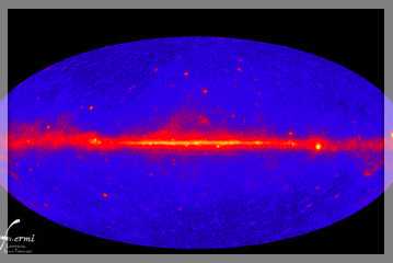
And there were hints of the pervasiveness and energy of
the lambda ray background radiance:
The ever-present fog of energetic gamma rays
permeating the
universe isn't created by what astronomers expected, new observations
from NASA's
Fermi Gamma-ray Space Telescope reveal, leaving scientists with a new
cosmic
mystery to solve.
<big clip>
But what the unknown source turns out to be isn't the important part
of the finding, said Martin Weisskopf, Chandra Project Scientist
from NASA's Marshall Space Flight Center who isn't involved with the
Fermi team. What matters is that "there is apparently a population of
gamma ray sources out there that one cannot identify," he said.
"This view of the gamma-ray sky is constructed from one year of Fermi
Large Area Telescope (LAT) observations.
The blue color includes the extragalactic gamma-ray background. The
map shows the rate at which the LAT detects
gamma rays with energies above 300 million electron volts —
about 120 million times the energy of visible light —
from different
sky directions. Brighter colors represent higher rates."
CREDIT: NASA/DOE/Fermi LAT Collaboration [original caption]
[The strong signals from the galactic plane of the Milky Way are no
surprise,
but that there is a considerable "fog" or bright background of them
coming
from all directions, apparently is, and it indicates energy available
for harvest
anywhere, anytime.]
And from another site:
http://www.nasa.gov/mission_pages/GLAST/science/gamma_ray_background.html
From as far back as the late 1960s, orbiting observatories have found a
diffuse background of gamma rays streaming from all directions. "If
you
had gamma-ray vision and looked at the sky, there would be no place
that would be dark", says Large Area Telescope (LAT) team member
David
Thompson of NASA's Goddard. [my emphasis]
Possibly the lambda ray "fog", rays above
perhaps 100 GeV, is even thicker and more of a uniform glow than the
'regular' gamma ray range, since
people have harvested radiant energy without reference to orientation
of the collecting device. On the other hand, it might be distributed
much as in the image above, and further experimentation might show
differing results attending differing orientations.
Understanding more about the energy - it characteristics
and where it comes
from - is likely to lead eventually to new generations of better
collection
devices
and perhaps unanticipated developments.
For now, it is probably
enough to know that the powerful radiant energy is real, everywhere
present and harvestable by the right techniques, and that "radiant
energy
collection devices" besides solar panels do appear to exist and to work
more or less as claimed, even if
their makers so far haven't known, or have had wrong or hazy ideas
about, the
source of the energy.
http://www.TurquoiseEnergy.com
Victoria BC