Turquoise
Energy Ltd. News #71
(December 2013)
Victoria BC
by Craig Carmichael - January 6th, 2014
www.TurquoiseEnergy.com
= www.ElectricCaik.com
= www.ElectricHubcap.com
= www.ElectricWeel.com
Highlights:
Lambda Ray Collector Experiments
Month In Brief
(Project Summaries)
- Battery Making Book -
centrifugal torque converter - lambda ray collector - evacuated steam
radiator tubes - a forgotten planetary gear torque converter video from
Sept. 2012 shows it was working better than I remembered (but still
needed a clutch - a part I couldn't seem to make decently!)
6 Years In Review
- oodles of projects!
In
Passing
(Miscellaneous
topics, editorial comments & opinionated rants)
Electric Transport - Electric
Hubcap Motor Systems
* Planetary Gear Centrifugal Variable Torque
Converter Transmission
Other "Green" Electric Equipment Projects
(No reports)
* Evacuated steam radiator pipes - Experiment with 12V Peltier module
refrigerator.
Electricity Generating
* Lambda Ray Collector - Brazilian Lambda Ray Collector
* Magnet Machines
Electricity Storage - Turquoise
(NiMn) Battery Project etc.
* Battery Making Book, URL: See December in Brief. (no separate report)
No Project Reports on:
DSSC
solar cells (will probably abandon), LED Lighting, Pulsejet steel
plate cutter, CNC Gardening/Farming Machine (sigh, maybe summer 2014?),
Woodstove/Thermal Electricity Generator (will probably abandon),
individual EV
battery monitor (will probably cancel).
Newsletters Index/Highlights: http://www.TurquoiseEnergy.com/news/index.html
Construction Manuals and information:
- Electric Hubcap Family Motors - Turquoise Motor Controllers -
Ersatz 'powder coating' home process for
protecting/painting metal
Products Catalog:
- Electric Hubcap 4.6KW BLDC Pancake Motor Kit
- Electric
Caik
3KW BLDC Pancake Motor Kit
- NiMH Handy Battery Sticks, 12v battery trays & Dry
Cells (cheapest NiMH
prices in Victoria BC)
- LED Light Fixtures
(Will accept BITCOIN digital currency)
...all at: http://www.TurquoiseEnergy.com/
(orders: e-mail craig@saers.com)
December in Brief
December turned
into a month of things that sounded good in principle, but didn't work
out well in practice. The centrifugal torque converter bumped the Chevy
Sprint into motion, barely - but with more vibration than motion. I'm
starting
to wonder if it's a workable idea with my meager machine skills. I
can try to get the same converter to run more smoothly in spite of
seeing that it needs to be wider to reduce the loads on the plastic
parts, or I can start over with a wider unit.
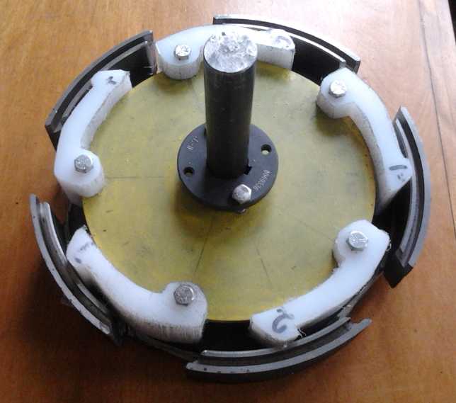 The essential mechanism.
Springs were added to the shoes later.
The first version of a lambda ray collector whined at the
(audible)
pulse frequency and put out 32 volts into a 400 watt electric heater
(36 ohms). The two brief times this happened (2 or 3 seconds each) were
its last two runs
because it was using far too much current and the power mosfet burned
out.The
heater would take 28 watts to get to 32 volts, so with 35 watts driving
the control coil it doesn't sound like
much of a success -- but there was no path for the input energy, which
was the same as on previous unsuccessful attempts, to couple more than
about 4 volts through to
the output coil by transformer action. And the "secondary" windings
were at right angles to the "primary", not in-line, so it wasn't even
configured as a transformer. So, as far as I can figure it, the 32
volts and 28 watts had to be coming from somewhere
else: presumably from lambda ray energy. The success came when I moved
a wire from 'ground' to the floating 'minus' on the power supply. The
other end of that wire didn't quite touch the collector coil wire, so
the appearance was of making it work by moving an unconnected wire.
This unit had used an external square wave from a signal
generator. In order to reduce the input currents, I redesigned the
circuit with its own short pulse generator, and used the whole coil
instead of 1/2 the turns. (circuits
are in the project report.) This version seemed to do nothing much in
initial testing. However, I'm not finished trying
various things out.
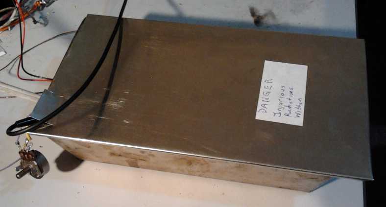 The collector - in a bread pan with a
nickel-brass cover.
The collector - in a bread pan with a
nickel-brass cover.
I strongly suspect dangerous radiations are possible with something
that converts rays from the high energy end of the spectrum.
Below lambda rays are gamma rays, x-rays, ultraviolet, visible,
infra-red,
microwave and radio waves, not to mention the charged particles
generated.
On an impulse looking at one of my evacuated radiator
pipes at the start of January, and thinking perhaps to get something
to
actually work right for this newsletter, I tried making an evacuated
pipes
with ammonia in it. I tried testing it on the fridge, but it didn't
work well. Sigh! But the biggest
problem was that the aluminum block, absorbing the heat from the
peltier module warm sides, wasn't transferring heat well to the pipe.
So the the block got up to 50°c and the pipe (under 40°) never
had a good chance. Even so, there were just a few little pings of the
ammonia
boiling a bit. I must do something about the block-to-pipe heat
transfer, try to get a stronger vacuum in the pipe with a bigger torch,
and test again soon. The
lures of silent refrigeration, with lower loss of coldness through the
unit when it's not cooling, and the potential of thermoelectric heat
pumping for home and EV heating with 1/2 the watts, are still there.
 "Evacuated"(?) radiator pipe clamped onto
Peltier modules of refrigerator.
"Evacuated"(?) radiator pipe clamped onto
Peltier modules of refrigerator.
Ni-Mn 2.6v Battery Making Book
Having what appears at last to be a reliable, working
battery chemistry, I decided I should try and put some battery making
instructions on line. But the tome, which I started long ago and
revised and revised several times as things changed, was a large
undertaking. I settled for editing the first two chapters and part of
the third, and directing people to Turquoise Energy News #60 to #69 for
more up to date battery fabrication information.
At the same time, I cautioned readers that while the
chemistry (at last!) all appears to work, I still haven't got batteries
that perform up to anything like the current and amp-hours capacities
they ought to have. That applies to batteries I make of any chemistry,
not just nickel-manganese. I think they need stronger briquette
compaction and better "grille" type current collectors within the
briquettes instead of just plates pressed onto the faces, to attain
better internal conductivity.
The Book may be found here:
http://www.saers.com/recorder/craig/TurquoiseEnergy/BatteryMaking/BatteryMaking.html
Energy Generation
When the weather turned cold a few days into December
I looked on youtube and found a video about magnet machines with a link
to a website, www.magnetmotorhojo.com
, where they were selling detailed instructions for making Howard
Johnson type self-turning magnet machines. I paid my 47$US, and found
not only the book but instructional videos. There was considerable
material but after scanning it I seemed no farther ahead. I've seen the
Johnson patent before. It seems to me the
biggest problem with the Johnson design is it uses magnets shaped in
cross section like crescent moons magnetized between the two "horns",
which shape and magnetization is evidently critical
and which I've never seen for sale.
That's probably a barrier that's
kept most people from making one. The design shown in the videos was
different, and they did list supply sources, but it looked rather hokey
to me - made by cannibalizing some small motor. It didn't look like
something to make much of a start at eliminating hydro with.
On the 10th I checked my e-mail... evidently for the first
time since I sent the November newsletter... and found someone had sent
me info on what could only be Lambda ray collectors ("Earth Electron
Capture Units") being made in Brazil, and a couple of
people had sent thoughts on torque converters. I wrote to the
Brazilians hoping for more info. An excellent design in the hand might
be better than months of my own experiments to get something to work at
all. I considered buying one, but 5500$ was a lot of money. The design
patents were on line, and while they had some
interesting features, they weren't all that different than others. I
didn't get a reply, and their units were seized and they were arrested
- really, kidnapped - then released. But they may be being prevented by
the corrupt from continuing their work.
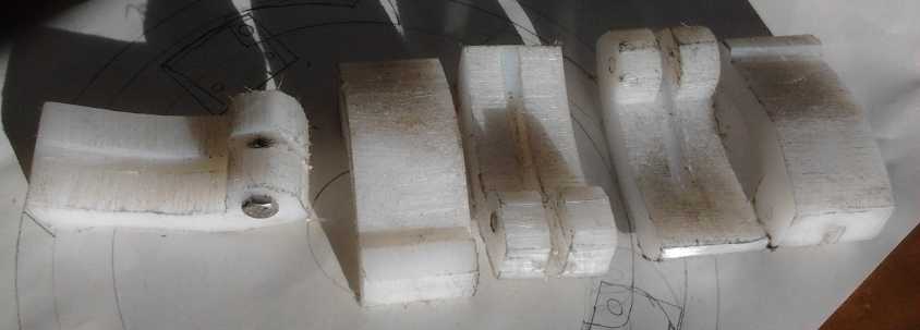
Centrifugal Torque Converter
I made a new drum from a 10" O.D., 9" I.D. brake drum,
cutting 5 slots with
end walls at 45° angles. Then I made an inner rotor from a 7.5"
disk rotor I
had cut for an Electric Caik motor a year ago. I got 1.5" thick UHMW
polyethylene and made five shoes with bandsaw, drill press, belt
sander, and a small 5.5" circular plywood blade mounted in the wood
lathe.
As I worked I got better ideas and more of a feel for how
it should go together and work. The 45° angles weren't really
45° because
the pivot pin of the shoes was an inch inward from the drum and not in
line with the slot wall angles. Pointing from the pivot pin to the
forward end wall, the angle was almost 90°, which meant the pawl of
the shoe might jam against it (stalling the motor) after the hit,
instead of bouncing inward. But the closer it was to 90° without
actually stalling, the more motor energy would be transferred to the
drum as output torque bumps. An optimum angle to hit at had to be
determined. With too glancing a blow the motor would just speed up
freely without imparting much torque to the drum. With too heavy a
blow, the motor would be too loaded down to pick up much speed, and the
"reduction ratio" from the slow motor to the car would also make for
insufficient torque to move it.
In reverse the 45° slots were also wrong. The pawls
would be being pulled away from the drum and would barely strike it.
The angle for reverse had to be greatly increased, perhaps to an actual
backwards hook beyond 90°. I decided to just leave extra material
on the pawls for reverse and shape them later.
On the 16th I had everything together to try out on the
table. Sure enough, it jammed going forward and hardly brushed the drum
going backward.
I then considered that the shafts had to be held securely
in alignment in the car, and accomplished that with a
sintered bronze bushing held in an SD coupling extending a little past
the end of the motor shaft, with the output shaft running inside the
bushing. Good enough for testing purposes, but even so it cracked.
I finally tried it on the car at the end of the month. It
kept jamming (extra cutting to even things up made for problems), so I
took it off and put springs on the shoes. That helped, but the hits
were lumpy and uneven. Some did little. Others bumped the car slightly
ahead (which probably took only 50 foot-pounds from where it was
sitting) but in doing so, momentarily brought the motor almost to a
stop. The car did more shaking around than moving. There's one or two
more things I can try with only modest changes.
After that, I confess I pale at the thought of having to
redo
everything again, perhaps more than once, to arrive at a really
satisfactory design. I hope this one is at least sufficient for a good
proof of concept!
To top it all off, I left the video camera in the rain,
and for the the last tests, I had to get out my old one, which I can't
edit the videos of. In reviewing the tests, I went back a little
farther and found the last one from September 2012. In that video, I
had managed to drive the Chevy Sprint forward several feet from where
it was into the shed, and had to stop before it hit the bench. I don't
remember having been that successful with the planetary gear
torque converter, but there it was on video! Once the PG torque
converter starts the car moving, it does work. I've described it as a
"divide by zero error", but really I still don't really understand why
it doesn't work until the car is in motion.
Perhaps a flywheel on the motor really was all that was
needed to get it going. Even if not, the PG converter concept worked,
except my crappy flat belt clutch construction wasn't up to the task.
Maybe a more "regular" sort of plate clutch to engage the chain drive
sprocket would make it work.
If I don't get the centrifugal converter working better in
a couple more tries, I may revert to that idea. So far, then, the
magnetic impulse, slipping planetary gear, and centrifugal torque
converters have all come close to working without quite making it,
evidently owing mainly to me "underbuilding" some of the pieces. It's
pretty frustrating!
Six Years in Review
I must be making a mistake somewhere... SIX years of
doing renewable energy projects? Let's see... 2008, 2009, 2010, 2011,
2012,
2013. That's only... hmm, six! That's not counting the early ocean wave
power ideas and designs of 2006 and 2007. My 59th birthday struck with
this new year.
What renewable energy things have I done or tried to do in
those six years? Going through the newsletter indexes is a pretty
boring read. Certain intransigent projects appear over and over again
in most issues for the whole time or much of it, with seeming promises
of success just around the corner being dashed an issue or two later,
and often the expectations of performance or function not being met.
Many might say I took on too much without knowing enough about the
subjects. Certainly my efforts have been spread very thin.
Yet over the time, main objectives have been creeping
along, and for relief, interesting projects and progress have been
accomplished in many energy related fields.
There have been some main projects, and some derivative
projects resulting from them. Some have achieved success, others have
been little more than concepts, or projects that haven't gone very far
- at least so far. A few I've sidelined because I started working on
other, more promising lines of progress that would make them obsolete
anyway.
List of Projects
* Ocean wave power
* An electric motor for car wheels
* Better batteries
* Some sort of efficient torque converter transmission - many tries to
get anything that would work:
- inertial
- magnetic
- magnetic impulse
- slipping planetary gear
- centrifugal
* Nanocrystaline "ultra-efficient" motor coil cores
* Nanocrystalline titanium dioxide borosilicate glaze frit to improve
solar collector performance
* Dye sensitized solar cells
* Lead-acid battery renewal with sodium sulfate
* An electric car heater
* NiMH dry cell car battery (in car almost 3 years now, still works
great)
* Building bigger batteries from NiMH dry cells (several constructions)
* Simple battery tab spot welder
* Pulsejet steel plate cutter
* An electric outboard motor - 3 projects (a working transport
application for my motors!)
* Huge torque "Electric Weel" motor for vehicles
* LED lighting
* Solar panels and low voltage house wiring
* A thermoelectric refrigerator
* Magnetic heat pumping
* CNC farming and gardening machine
* Electric Caik motor - a smaller version of the Electric Hubcap
* More efficient outboard propeller - aluminum casting.
* Woodstove/heat source
thermoeletric power
* A thermoelectric heat pump using less electricity than a regular
electric heater
* Evacuated steam tube heat or coldness radiators
* Magnetic machines, magnetic
spacecraft drives - my theory of thermomagnetism
* Vertical axis wind turbine
*
A radio wave energy collector
* Lambda ray collector (after identifying the source of the unknown
radiant energy people seem to have been capturing for a century)
In regard to generating electricity, I have
become quite convinced from many sources that people actually do get
power from self rotating magnet machines, and actually do 'collect' the
incredibly energetic lambda rays which are all around us and get
kilowatts of power from them. In fact, judging from the wide variety of
designs on the web, this last is rather easily done. To paraphrase a
phrase, such devices would "create solutions rather
than fix problems." Solar, wind and thermoelectric power generation
pale beside these grand possibilities, so there seems to be little
point in continuing with them.
For those still useful projects and ideas that
I can't bring to a successful conclusion myself, and there
obviously will be some if only because there have grown to be so many,
I
hope writing about them in these newsletters will inspire others to
take up the projects, or even more worthy successors to them, and make
their fruits available to the world. (My latest idea is to see if the
Victoria
"maker community" would like to have something along the lines of a
monthly "energy night" where people build an energy project of their
choice. If I could help guide this, it might speed design evolution as
well as dissemination and adoption of some of the projects and designs.)
Getting down to specifics,
the four main projects related to car "hybridization" have been
the main focus throughout these six years. The Electric Hubcap and
Electric Caik motors are probably the most complete projects. The
Electric Hubcap took a long time before I had a really excellent
motor, being one of the three I started in January 2008. Since the Caik
was derived from the Hubcap and uses mostly the same parts and
constructions, I developed it in just 3 months at the end of 2012. I
can now make a great motor whenever I need
one, and I hope to teach others how to do so as well.
And yet, I have in mind a couple of ideas for improved
jigs,
and even this month I've had an idea for a motor improvement: a
metal rotor-end cover plate, which should be better for attaching the
bearing and a solid mounting to than the PP-epoxy composite. The
Electric Weel and bicycle rim motor should be little harder to make in
principle, but require input of design time to make the molds and
templates/jigs before they can be produced.
Next up also from January 2008 is the BLDC "Turquoise
motor
controller". They've been working reasonably well since 2011, but they
still aren't totally reliable unless limited to 24 volts or to too low
a current for street vehicles. (Next I'll try shielded gate drive wires
to prevent glitches, and move the PC board a little farther from the
high power MOSFETs - little things like this are critical to prevent
spurious switching leading to failures at high power in such fast
switching, high powered circuits.)
The final project with that same start time is the
Turquoise Battery Project, in which the last pieces of the
electrochemical puzzle have at last come together to yield an excellent
battery chemistry: Ni-Mn with KCl electrolyte, "moderately alkaline"
cells. There've been many puzzling failures and successes that proved
to be only partial along the way, so they limped along always holding
out the elusive
promise of fabulous, cheap batteries. The chemistry at last seems to
be complete and working, with cells holding that great 2.6 volt charge,
in 'any' weather and with repeated charging. They now need to be
constructed so that they fulfill theoretical expectations, with good
current capacity and good utilization of the active
chemicals. I've decided that that's not my priority for now - or
probably ever if others like Changhong Batteries start making them. If
not (they didn't reply to my e-mail), perhaps I'll have a go at
production quality cells someday. But that I've spent
six years on these projects to get this far are a reminder that life on
this planet is
finite, and realistically, the day may not come.
The fourth main project, the torque converter, was started
in
May or June 2009 when
I finally realized that a motor that could directly drive a car wheel
would be too heavy and bulky to mount on that wheel. To my surprise,
even
with a 4 to 1 reduction the motors would barely get a heavy frame
motorbike
going (and only with batteries and a controller capable of powering it
strongly, without fading or blowing).
Any fixed gear ratio that would allow a vehicle to start from a stop
and
accelerate well at low speed, seemed like a good way to waste
electricity with high RPM.s at driving speeds, especially on the
highway. A compact, efficient, variable torque converter that would fit
between the motor and the wheel became another "holy grail" project
that would go on and on, with some frustrating "almost works" magnetic,
planetary gear and centrifugal units that weren't quite practical. So
far.
So far, the only really successful electric transport
achieved by my motors and controllers are two versions of an electric
outboard motor for boats - the original November 2010 conversion of a
Honda 7.5HP with a primitive version of the motor, and the February
2013 launch of the same Honda outboard with the newly created Electric
Caik motor. Yet conversion of an existing outboard has its
frustrations. With land transport, I can't seem to get enough gear
reduction efficiently. With outboards too much reduction is built in,
down at the propeller. And the propellers, it would appear, could be
much more efficiently shaped.
In some frustration, I took on an old "regular" converted
electric car in 2013, generously offered by Jim Harrington,
which turned into a considerable - and ongoing - project in itself.
(...now it's short two PbPb batteries again, and the hydraulic clutch
pedal
has died and
its removal bolts are virtually inaccessible.) But it runs, I drive it
on the street, and I've learned some things from it. On the other hand,
it has taken up a lot of time that might have been better spent getting
a working torque converter, making thermoelectric heating, and other
projects.
Skipping to 2013, the highlights are doubtless:
* the finish of the short development of the Electric Caik motor
* the successful running of the Electric Caik Outboard
* the final links to get the new and better NiMn battery chemistry
working
properly after so many years
* the findings about the lambda rays: of the existence and nature of
free, powerful radiant energy that really is all around us, day and
night. This extension to the electromagnetic spectrum beyond gamma rays
has been "known" for over 10 years, but hasn't made it into the general
knowledge stream - it hadn't even been given a name and people haven't
been waking up to its radiative characteristics or its potential for
energy generation.
Also worthy of mention are:
* I created click-lock versions of the "CAT Standard" 12 VDC plugs and
sockets,
* I started in (but didn't get very far) on thermoelectric heat pumping
for space heating to double the effectiveness of whatever electricity
was used for heating,
* and on evacuated steam tubes for heat radiation for the above,
* I made 3D printed 12 volt NiMH "D" cell battery cases (and improved
my techniques for soldered-together battery packs),
* I got the electric Mazda RX7 with all its seized-up parts running and
back on the street.
* I've been working on a centrifugal torque converter. This is a
promising converter type that does everything automatically (no clutch
or gear shifting), and I'm getting more of a
handle on the requirements and parameters. It ought to propel
cars.
*
The 'shallow chest' thermoelectric fridge made in summer 2012 continues
to work nicely and I keep food in it, albeit I *still* haven't made any
automatic control for it and operate it manually, more on than off, on
a daily cycle.
Since energy issues are so closely tied to social issues
in our dead-end and failing civilization, my idea for a referendum
web site where anyone can propose and vote on a referendum on any
topic, by interactive creation of choices and choice ranking voting, of
any geographical or other scope, should probably be
mentioned. In addition, I plan to narrate my booklet Fundamental
Principles of Democratic Government - towards utopian systems of
governance and put it on youtube, where it will doubtless reach
a far larger audience than it appears to have so far.
In Passing
(Miscellaneous topics, editorial comments & opinionated rants)
Unicorns
 In TE News #69
I recounted the discovery of fossils of the
giant flying bird Argentavis, probably in the "teratorn" family of huge
flying birds. It could carry people or livestock, and is probably the
'roc',
'fandor', maybe the 'griffin'. It was written about as still living in
historic times in Southeast Asia by Marco Polo and by naturalists, but
until the discovery of the fossils, their accounts were dismissed as
'legends' by more recent scientists.
In TE News #69
I recounted the discovery of fossils of the
giant flying bird Argentavis, probably in the "teratorn" family of huge
flying birds. It could carry people or livestock, and is probably the
'roc',
'fandor', maybe the 'griffin'. It was written about as still living in
historic times in Southeast Asia by Marco Polo and by naturalists, but
until the discovery of the fossils, their accounts were dismissed as
'legends' by more recent scientists.
To carry on with the theme, it appears that the
'legendary' unicorn was probably a species of fleet footed rhinoceros
- or perhaps more than one species - with a single long horn, that were
once very common but went extinct (overhunted?) around
10000 years ago, of genus Elasmotherium. The legs of this tall
species were more akin in length to horse
legs than to the short legs of extant rhinoceros species.
Hidden Secrets of Money - Video Series
This is a plug for Mike Maloney's five part video series, Hidden
Secrets
of
Money. As Maloney points out, people who understand how
the money system works, who understand how banks and governments
may collude to scam us and steal our wealth, and who understand what's
coming upon us, will prepare accordingly and be better off than those
who don't. So the best thing you can do for your own future is to
educate yourself. And the more people there are who understand, the
more
pressure there'll be to end the stealthily pilfering financial system
and put something sustainable and fair in its place.
Maloney isn't the only person saying these things, but Hidden
Secrets
of
Money does it with good clarity in an entertaining,
watchable style. Search for "Michael Maloney" on Youtube. (He does not,
in this series, touch on Bitcoin, and the viewer should realize he
threw himself into gold and silver before Bitcoin existed. Nor does he
touch on related matters such as the need to put away food for a period
when the supply chain may be disrupted for an extended period by the
chaos of the
financial collapse he expects. But it's a great video series about
money!)
1. Gold and silver: Money versus Currency
2. Gold and silver: 7 Stages of Empire
3. Demise of the Dollar (and every other fiat currency in history -
thousands of them)
4. When Money is Corrupted
5. The Biggest Scam in the History of Mankind
Free Energy Inventors - Suppressed?
The Brazilian inventors of the lambda ray collectors have
run into flak, to say the least. One would hope peoples' natural
reaction might be one of wonder, and enthusiasm as they realize how the
fact of almost free energy in abundance will change the
world forever for the better. Instead the people sent saw the simple
answer to the world's perplexing,
entrenched energy problems of a century and more, right before their
eyes -- and they were indignant. Maybe they already had their orders.
They stole ("confiscated") the
installed devices and had the inventors arrested in what amounts pretty
much to a kidnapping. (They were later released. Now I hear a rumor
that unlike the ever-frauding big banks, they've been charged with
"fraud".)
Here's some questions for those who think that if Barbosa
and Leal were charged with fraud, they must have had no actual success
and been trying to defraud:
* If they had no real product, if they really were running a scam, why
were they willing to sell only locally, using their real names, so
their
intended victims could see and try out the merchandise before buying,
and "know where they live" if they found they had been cheated? It
would be more natural to sell over the internet only, to points abroad,
under pseudonyms, and avoid local sales.
* If they really were trying to run a scam, amidst all the scams being
run and succeeding for a while before the police catch up, if they ever
do, how is it that the authorities came prepared with power company
officials to immediately disconnect and seize the equipment, and
seemingly "threw the book at them" -- no warnings and evidently without
even a
customer complaint to justify pressing of charges? At that point, it
was only a potential fraud. And they were first arrested not for fraud
but for having "stolen" electric power meters. No one bothered to ask
how it was they had them (they were given them by a utility employee)
before carting them off to jail.
* If their inventions don't work, how did
they get two or three patents on them?
Nobody seems to like
the inventors or their product... except probably the 99.99%, who would
immensely benefit. But the way this world is being run today, their
feelings, wishes and needs - our
feelings, wishes and needs - and the planet's future, count for naught.
A news report about it (see on youtube) noted at the end that many
promising
energy inventions such as this have come along, made the news, and then
disappeared and
nothing more is
ever heard, noting that one petroleum
saving inventor's last words as he collapsed in a parking lot were
"I've been poisoned!"
This is a reason why we need the coming global collapse
and
"reset". Today the
internet is preventing the corrupt from controlling the dialog, and
manipulative false flag events are being seen for the lies that they
are, for example thwarting at least for now the US led attack on Syria
(intended to help dominate and control the middle east for its
resources). Even now, global consciousness is rising. Hopefully these
Brazilian inventors may be able to continue their work in
peace.
Peace, forgiveness and love are the attitudes that will
loosen the grip of evil on this world and see it progress. Corrupt
overcontrol by a few family cliques of "reprobates" is what has been.
It will soon be a part of history, not of the planet's utopian future.
I've heard that when the time comes (probably within our lifetimes)
the top "reprobates" are to be "unceremoniously removed
from the planet so they can work no more harm", and taken - their souls
taken -
for special rehabilitation. Thus, problems that seem beyond human
solution
will be solved nonetheless. The
bunkers, island or fortified homes and fallout shelters won't help
those who would enslave humanity and who have made working of evil into
an art form. What would help them is turning around and living a
righteous life.
Some
of them will choose oblivion over eternal life owing to the way they
lived their Earth life. Forgive them. Pray for them.
Of course, partly the reaction of the power company people
may be a natural human reaction to having one's view of the world
jarred.
All our lives we've "understood" that energy is scarce and costly, and
easiest to get from oil. To find that energy can be freely and easily
collected from the air changes everything we thought we knew - the
whole way the world works and relates to energy. As one scientist put
it in a book (stop me if I've told this one already), the way to get
your theories accepted is:
1. Publish your work.
2. Wait for the current generation of skeptics to die off. They will
never believe regardless of anything. It is surprising to find that
this is as true today as it was in 1610 when Galileo was placed under
house arrest for discovering Jupiter had four previously unknown
planets orbiting it, made plainly visible with the telescope. And
again, if Galileo was just spouting fantasies, he would have been
dismissed as a nutcase, not arrested. It's those that have something
new that are feared.
If the work is true, the next generation will incorporate
it into humanity's knowledge database. In the case of lambda ray energy
and probably magnet machines
however, the time is coming that people are increasingly
not going to be paying hefty monthly fees to a power grid to run their
homes and businesses, and then even the skeptics won't want to be still
doing so.
Nasty Iran: a continuing threat to peace
Here's a little
diagram I found of American military bases near Iran, which has just
democratically elected a new president. For decades now we've been told
that Iran is a crazy country that is almost ready to make nuclear
weapons, and as soon as it does, mayhem will break loose.
Iran is
surrounded by nations holding nuclear weapons on their soils. So what's
it
really all about? Iran is selling its oil for currencies other than the
US dollar, and more especially for gold. The last two countries to try
that were Iraq and Libya - look what happened to them. But having been
invaded by Iraq, and
then threatened for so long, Iran has built up a considerable military
and
would be no pushover. Before the USA could invade it, it would need a
short,
secure supply route via the Mediterranean, through Syria and Iraq.
In the 1950s (1952?) the CIA paid some malcontents to
stage demonstrations, and managed to oust the first and newly elected
president of Iran, and have a puppet, the shah, installed in his place.
It was the easiest takeover of a country ever, and became a model for
the corporatocracy's "banana republics" treatment of Latin America for
the rest of the century. The book Confessions of an Economic Hit Man
shines some light on this dark era.
That doesn't seem to
work on Iran any more. I must say the diagram reminds me of a map of
Poland just before Germany invaded it from all sides to start World War
Two.
 from Keiser Report ...#5XX
, December 2013
Electric
Hubcap Motor Systems - Electric Transport
Centrifugal
torque converter transmission
Notwithstanding the poor results in November - and I
suppose owing to my failure to make a working clutch for the planetary
gear converter - I became
convinced the centrifugal torque converter was the best way to go. So I
started looking for more suitable parts - mainly something better than
an old frying pan for a drum rotor.
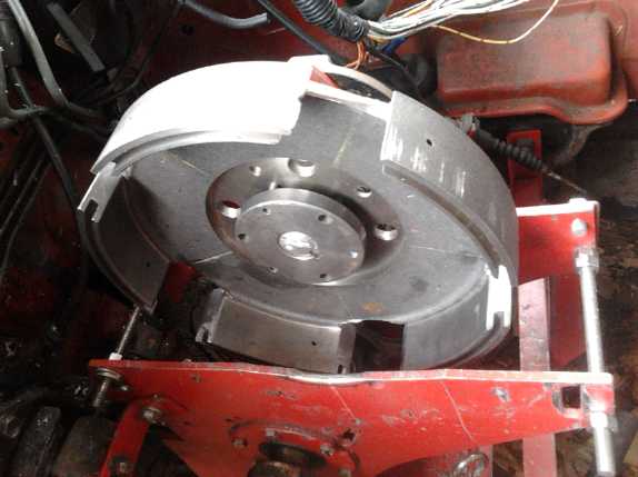 I got an 8"
I.D. aluminum pipe, 3" long and wondered how
to mount it without machining a whole end plate to exacting specs. I
got out an old brake drum to see how it would fit in it. The fit might
have worked if I cut the aluminum pipe to 2" width or less. But then I
thought,
why not just use the brake drum? A chief reason in my mind was that
being steel it
would rust mounted on a car wheel. The abrasive rust would wear out the
plastic "shoes" (which I was calling "fingers" in last month's issue).
Well, I wasn't putting it on a wheel now, and anyway proof of concept
was the objective at this point. The brake drum was of course properly
machined smooth and round, 9" I.D., 10" O.D., and the center hole size
(as luck would have it)
was just right to fit an SDS taper lock bushing to mount it on the
shaft.
The drum inside walls would allow for up to 1.25" wide plastic "shoes".
I still only had 1" thick plastic, but that would at least give some
slack
for misalignment. (After finding one used drum of this type in a brake
shop garbage bin, I had bought this one new in a much much earlier
failed attempt to make a converter, and if it's so perfect I want more
of them, I trust I can find the part number in some old issue of
Turquoise Energy News.)
I got an 8"
I.D. aluminum pipe, 3" long and wondered how
to mount it without machining a whole end plate to exacting specs. I
got out an old brake drum to see how it would fit in it. The fit might
have worked if I cut the aluminum pipe to 2" width or less. But then I
thought,
why not just use the brake drum? A chief reason in my mind was that
being steel it
would rust mounted on a car wheel. The abrasive rust would wear out the
plastic "shoes" (which I was calling "fingers" in last month's issue).
Well, I wasn't putting it on a wheel now, and anyway proof of concept
was the objective at this point. The brake drum was of course properly
machined smooth and round, 9" I.D., 10" O.D., and the center hole size
(as luck would have it)
was just right to fit an SDS taper lock bushing to mount it on the
shaft.
The drum inside walls would allow for up to 1.25" wide plastic "shoes".
I still only had 1" thick plastic, but that would at least give some
slack
for misalignment. (After finding one used drum of this type in a brake
shop garbage bin, I had bought this one new in a much much earlier
failed attempt to make a converter, and if it's so perfect I want more
of them, I trust I can find the part number in some old issue of
Turquoise Energy News.)
I cut the slots 1.75" long (inside length) and at 45°
on the 8th. Since I was using an angle grinder rather than precision
equipment, that was followed the next day by several hours of grinding
and filing to get things as straight and true as my stamina and time
allowed. The slots were 2" long or slightly more (and not very evenly
spaced) by the time I was done.
As suggested by Eric Jenkins at the VEVA electric car
club, I might try steeper slot angles. If the motor didn't have enough
coupling to the wheels and just spun up easily without making much
torque, as happened with the frying pan version, I could steepen the
angles by grinding away the outsides more. I could see going up to 60
or 70° - maybe even 80° or more - to increase the force of each
blow. This would also change the angle of the resulting force vector,
becoming more of a straight on smash, the forces of which would slow
the motor more and speed up the drum more - more torque transfer. But
the angle
would still be enough that the "fingers" on the shoes would bounce out
and not stall motor rotation. The more I thought about it, the more I
suspected I'd had the blinders on about the 45° angles. Finding the
optimum fairly steep angle might well be the key to getting optimum
coupling force between motor and wheels.
On the other hand, having twice as many 45° slots
would provide twice as many lighter hits per rotation and hence twice
the torque transfer without changing the angle. At that point, with 2"
long
slots, there'd be more slot than wall, and triple or quadruple slots
would be out of the question. The question of angles soon became the
main point, when I considered the shape to make the shoes.
A 1/4" x 7.5"
O.D. rotor cut nearly a year ago for an
Electric Caik motor (I had four rotors done when I made the first Caik)
seemed pretty much ideal for the inner (driving) rotor to mount the
"shoes" on. That made a 3/4" space between the outside of the driving
disk and the inside of the driven drum. I had sized the disks' center
holes for smaller taper lock
bushings, size "H" instead of "SDS". I had "H" bushings
for 7/8" and 1" shafts, but the motor had a 1-1/16" shaft end. I didn't
relish changing the motor shaft, so the next day had a shopping trip.
Somehow I was already sure that would be all I got done that day, and
sure enough, no one had one and I had to buy one with a 1-1/8" center
and make a sheet steel insert, a shim. Not before trying all the places
that just might have one.
(Later I found a "7.8 inch brake disk" with a center for a
keyed 1 inch shaft at Princess Auto. This would have made an ideal
inner rotor for a motor with a 1" shaft. In fact, it might make a very
good "ready made" magnet rotor for Electric Caik motors!)
On the 11th I bought some 1.5" thick UHMW-PE plastic (and
some 2.0") and on the 12th I started in on a design for the 'shoes'. I
started to consider the strike angles not by themselves but as vectors
in relation to the shoe's pivot point. If only the small mass of the
shoe was considered, the hit was 45° and the shoe's bounce was
inward.
But the angle of the bounce could only be the angle from
the pivot pin, which would only be straight in if the pivot pin was
somehow just outside of the drum rim. That pin, which drives the shoe
around the drum, is about 50° around the rim from the impact and an
inch inward from the drum wall, resulting in a bounce angle of
almost 45° from straight in. it appeared that even with an optimum
length shoe, the 45° angle would in fact already be almost a
90° hit knocking the shoe against the pin, if the shoes faced
forward from the pin. It would be forced to bounce off at a very high
speed compared to the speed of the impact. If the shoe tip wasn't
rounded off, or if the slot angle was say 50° instead of 45, the
shoe might actually jam against the slot wall and stop the motor.
Tolerances being what they are, it might actually happen. A very steep
strike angle is evidently inherent in the design. In fact, in theory
the slot end walls ought to be slightly curved concave to match the
sweep of the pivot. The cog end wall would be slightly convex to match.
If on the other hand the shoes faced backward, or for
driving in reverse, the same shoe tip and slot wall angles would brush
by each other very lightly, with the pivot pin already pulling the shoe
away from the drum. Evidently the angles for the
shoe tips and slot ends should be completely asymmetrical between
forward and reverse, the reverse requiring almost a reverse hook in
order to effectively transfer the rotary forces from the disk to the
drum.
Little torque difference between
forward and reverse was seen with the frying pan. That made me nervous
about these surmises, but then it could hardly
be said to have been working properly, with the slots obviously too
narrow and flaking little chips off the
plastic in both directions. I decided to go with the steep angles idea
and leave some extra material on the shoes tips to shape the 'reverse'
sides later. If the car would drive only forward, it would still prove
the centrifugal torque converter concept -- the shapes for the other
direction could be worked out later.
On the 14th I finally decided on a shape for the shoes and
roughly cut them out from my block of plastic with the band saw. I left
some extra on the "pawl" end for adjustments and for shaping them for
the reverse direction later. On the 15th I drilled 5 holes in the rotor
disk for the pivots and shaped 2 of the 5 shoes. Doing the shoes was
slow going. I needed a better way.
As I did this, I started thinking there wasn't much free
play, and that it would be much better to somehow tie the two shafts
together to keep the disk and drum aligned, rather than just to rely on
lining up the motor approximately with the output shaft.
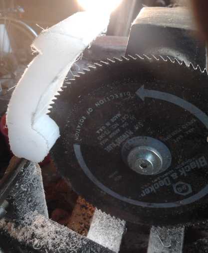 On the 16th I
found an old 5.5" plywood blade and mounted
it on my wood lathe to cut the remaining slots, butting the pieces on
the tool rest. It worked quite well and I had them all nicely cut and
adjusted in an hour or so. They all needed deeper slits than the
original shape allowed for, and it was nice to just dig into them
however much was required.
On the 16th I
found an old 5.5" plywood blade and mounted
it on my wood lathe to cut the remaining slots, butting the pieces on
the tool rest. It worked quite well and I had them all nicely cut and
adjusted in an hour or so. They all needed deeper slits than the
original shape allowed for, and it was nice to just dig into them
however much was required.
I made the pivot pin holes so that the 1/4" bolts slid
into one side, and threaded into the other side. It didn't seem they
were likely to turn loose, but it left the metal screw shafts pivoting
on the steel rotor, so they'd need oiling.
In spite of the loose driving V-belt and the slow speed,
the thought of my fingers perhaps touching the nearby saw blade wasn't
very appealing. I was very careful and only had 5 shoes to do, but it
certainly needed some thought about setting up for any sort of
production. Some sort of CNC tool might be best? Or at least a clamp
and screws to hold the pieces and move them around against the blade,
keeping fingers well clear.
Then I put the rotor together and fitted it on a shaft
with the drum. As I by now expected, the cogs usually jammed in the
forward direction. But even at hand speeds each cog hammered the drum
with notable force and made it turn a bit. This was encouraging. The
cogs breezed breezed by the slots in reverse with little force to the
drum. I made a little video of it. For the first time in this whole
project I felt like I was starting to get a good grip on the parameters
and requirements to make a centrifugal torque converter work. I thought
it would work if I got everything about right... and if the plastic
shoes didn't disintegrate.
Later I went to Princess Auto and got some sintered bronze
bushings. (None exactly the size I wanted - I shaped one on the lathe.)
The plan is to fit the
motor end of the bushing fixed under the "H" bushing, with the outer
end sticking out past the motor shaft. (And oil it!) When installing, I
would loosen the fittings and then push the output shaft end into the
open end of the bushing. This would hold the shafts in alignment while
allowing them to rotate independently.
Finally, I had noticed during the bench rotations that the
5 cogs didn't line up with the 5 slots evenly. Really, they were pretty
bad. The pivot holes were pretty evenly spaced, as were the shoe
lengths. Then I measured around the outside of the drum and found that,
careful as I had been measuring and drawing the angles, the slots were
quite unevenly spaced. I should have done the outside measures before I
cut the slots - and again during grinding and filing. (I should have
measured the distances between all the pivot hole points, too, but that
worked out pretty well regardless.) Also I got a 45° angle measure
and found some of the angles weren't very close - some were about
50° towards right angles. These would be the ones that jammed - or
jammed worst.
The total distance around the outside of the drum was
790mm, so 790/5=158mm from one slot front face to the next one. They
were actually from 153 to 163mm. One was 5mm short, one was 5mm long,
two of them were right WRT each other and the last was pretty close...
but all but one would need regrinding to even out all 5 spacings - and
that one needed its angle reground anyway - ouch! So the drum required
another day and a lot more grinding and filing to rectify.
It wasn't until almost the end of the month that I tried
the unit out. It jammed. I took it inside and put springs on the shoes.
Then it ran very roughly. The car moved ahead a few inches from a spot
where low torque was needed, but mostly it just shook.
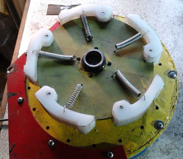 One guess which spring I wound myself
Other Green Electricity Projects
Fridge with evacuated(?) heat pipe radiator
clmaped onto
Peltier modules & copper "cold bar" going to ice tray inside.
Evacuated Pipes Attempt - for thermoelectric fridges and heat
pumping
On an impulse looking at one of my
evacuated radiator pipes at the start of January, and thinking perhaps
to get any something to actually work right for this newsletter, I
tried
making an evacuated pipe, this time with ammonia in it instead of plain
water. The first pipe had a leak.
The second one didn't sound like much of a vacuum, but it sounded
different than one with no vacuum. Maybe ammonia didn't behave quite
the
same as water? I put the radiator fins back on it and tried it on the
peltier fridge. I got the following temperatures:
- Peltier hot side (aluminum block): 47°c
- Base of pipe (inside aluminum block): 37°
- Top of pipe (after all the radiator fins): 27°
- Room : 17°
- Peltier cold side (to fridge): 7°
If the unit was turned off, the cold side (there was some
ice
in the
tray in the fridge) dropped to 5°. Needless to say, all this was
pretty
unsatisfactory and I had to reconnect the fan and heatsink (which gave
good performance:
- Heatsink: 27°
- Room: 17°
- Cold side: -1°. (The cold side would get no colder until it
froze all the water in the ice tray.)
However, I noticed in the days that followed that the unit
drew somewhat less current and cooled more slowly than before I started
- effects of poorer heat transfer. This would mean that I didn't get
the Peltier modules seated as well as they were before the experiment,
which in turn shows how critical it is to transfer the heat and cold
from the modules as effectively as possible. But I digress...
The first problem, before even getting to the evacuation,
was how on earth a pipe clamped into a hole inside an aluminum block,
and even the liquid inside that pipe, could have a temperature so much
different than the block. The heat transfer should keep them virtually
the same temperature. I took it apart and stuffed in aluminum foil,
added heatsink compound, and then tried copper foil, almost to no
avail. The copper foil helped a bit, reducing the difference to about
7°. Unfortunately the diagonal hole in the aluminum for the pipe
wasn't very smooth and even.
Perhaps I should get a copper block to put on the hot side
of the peltiers, and solder copper fittings to it to physically and
thermally connect the radiator pipe to it. Or sand the block down some
and re-drill the hole. But I would need a plan for getting it smoother
this time. The trouble is trying to hold the block on an angle.
Then there's the seemingly poor vacuum. Like last time,
pipe temperature was well up into the 30 s celsius before any small
'tings'
of steaming were heard. As I think about it, when I was trying to
evacuate the pipe, the propane torch didn't have as strong a flame as
usual -- likely the slower steam makes less vacuum.
This led to the thought that maybe if I want a better
vacuum I should use a powerful naphtha gas torch and have the steam
whistling out much harder before closing off the end cap. (And then get
the torch away quick before bursting the pipe. And with better vacuum
maybe I could use plain water.)
On January 3rd the friend who had given
me the two naphtha gas torches (quite some time ago) came over, so I
had him
go over how they were supposed to work and what I should expect.
Neither of them did what it was supposed to, but assuming I can adjust
the better one properly, I should be able to get a whopping powerful
flame to do
the pipe evacuations with. Then maybe the vacuum will be good
enough that the liquid will boil at or below room temperature. Maybe
even with plain water.
Evacuated tubes should work. It's not just the fridge - I
don't want to start in on the heat pumping for house and EV heating
until - and probably unless - I have them working well.
Electricity (Energy) Production
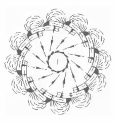
Lambda Ray Collector
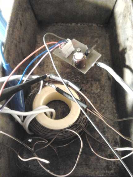
Lambda Ray Collector in Bread Pan with
Nickel-Brass Lid
- to contain any dangerous radiations or energies.
As electric rates here have just been jacked up 24%, the race is on to
find
truly effective alternatives to the offerings of the government, the
utility, and the 'for profit' "Independent Power Producer" companies.
Four big solar collectors haven't made much of a dent, winds here are
generally light, and I don't have waterfront or waves even if I was
permitted to set up an ocean wave power station across a beach, which
is doubtful. Geothermal would also seem to be out, and again a
woodstove thermoelectric generator would be a small dent in the total
bill.
That leaves lambda rays, powerful unseen energy coming
from across the sky and all around us, and magnet machines.
I can't pretend to know with any clarity myself what
happens inside a lambda ray collector. As per the table last month,
lambda rays are the only radiant energy energetic enough to produce "a
stream of particles and antiparticles" on interaction with matter.
But what exactly does this mean? The wires or other parts
of the collectors don't disintegrate as far as anyone has reported, so
from where are these particles derived?
One day, Physicist Jakovak came over and spent a couple of
hours in dissertation introducing me to the incredible world of
subatomic particles, of which there seem to be dozens if not hundreds
of types, and their interactions. There are indeed aspects of reality
undreampt of in my philosophies!
According to Jacovak,
apparently out of "empty space", electrons and positrons (positively
charged electrons) can form in pairs. This is apparently the potential
"vacuum" energy Fineman spoke of when he said the energy in an empty
cup could boil all the water in all the oceans of the world.
So perhaps the "vacuum energy" theory is right... but it's
brought from potentiality into actuality by the lambda ray energy. In
the
magnetic field of the coil, the electrons and positrons spin off in
opposite directions, preventing them from canceling each other and
returning to 'potential'. The needle-hook wire (below - see
developments December 18th onward) looped around one end of the
collector loop wire may have something to do with separating them and
developing a large voltage across what ought to be nearly a short
circuit coil of wire - just one to four turns.
Gold or Silver?
The file on the collector I started copying and the
experiments leading up to it found solder was better than copper for
collection coils, and mentioned that aluminum doesn't work. The solder
might work better than copper either because it had higher resistance
and so allowed a higher internal voltage to build up within the wire
(in which case the higher voltage was a negative thing), or because it
actually "collected" the rays' energy better.
If it was the latter as I started to suspect, it was
probably because the elements, tin and lead, were denser with high
atomic weights. That fits
with aluminum, being very undense and atomically light, "not working"
(or perhaps working
quite poorly). And denser elements might cause the rays to interact
with matter proportionally or disproportionately to the density - for
example, maybe by the square of the density. Or maybe it's proportional
to the atomic weight. Put together, there's more, bigger nucleuses to
hit in less space. For dense elements that also conduct electricity
very well, silver and gold should be good choices. For conductive
elements of high atomic weight, there's nothing else half as good as
gold. Understandably, gold wires weren't one of the types tried. If it
works
best as I suspect, it's not going to make the collectors any cheaper!
Silver would be more affordable since the amount of wire in the
collector coil is small. But it may be that all that's needed of the
heavy metal is a needle point near the collector wire. Even gold would
be affordable for that... at least at its current manipulated low price.
I started thinking that if they were getting a kilowatt
from a simple "moebius strip" loop of double wire that was probably
poorly efficient, the energy must be
even more concentrated than I thought. I started thinking a collector
"plate" such as Tesla had used would probably do better in a very small
space. I started thinking in terms of something like a "bread pan" for
the plate, and also as a cover for the unit to keep the energies safely
inside.
A friend wanted to get together and work on the energy
collector with me. This devolved down to looking at some info on line,
especially looking up some Brazilian units (below), and I borrowed a
signal
generator from him to make square waves up to 2MHz. This was the
missing piece to activate my unit. The Brazilians' high performance
unit appeared to be about the simplest design yet, with just one
control coil and a couple of loops of wire for the capture coil, and a
ground wire not quite touching the collector coil at one end. They
appeared to be using ordinary transformer laminates - which another
patenter, Tom Bearden, claimed wouldn't work. There were a couple of
puzzling features and their patent drawings might not tell the whole
story.
On Saturday the 14th, some friends and I sat around
discussing the energy and devices. The feeling of the others was that
since it sounded like there actually was energy there... they would
believe it when they saw it. That's a good step up from prejudiced
rejection, and stems from having a rational explanation of what such
radiant energy is and where it comes from. But I realized I would have
to demonstrate working energy collection, preferably very easy to
replicate, before most people would give my words much credence.
So now we have one patented design using unspecified
nanocrystalline material, and another using transformer laminates. Like
the crescent-moon shaped magnets required to make the Howard Johnson
magnet machine, neither of these core types are available for purchase
from any source I'm aware of. What sort of cores could be had? Of
course there's air core like the unit I started copying. Then, I have
the 2" x 1" toroidal iron powder cores that I wound the control coils
from. If I wound a couple of loops of wire around in the "regular"
direction through the center of the toroid, it should meet the
essential requirements of two magnetic circuits at right angles to each
other, and the frequency (around 100000 Hz is the plan) should be
plenty high enough to work with the low permeability of the iron powder
cores. And it would be very simple.
On the night of the 17th I wired up my
newly simplified circuit, and on the morning of the 18th I tried it
out. The driver board didn't work. Aside from an easily corrected
wiring mistake, somehow I had the P-channel and N-channel pre-driver
mosfets reversed. The mistake was elementary. I
must have been working too late at night when I made the schematic! The
miniature SSOP packages were the one component that would be very hard
to rewire without making a whole new circuit board, and I spent the day
designing and making a new board.
The thin glossy magazine paper jammed in the laser
printer, and after finally clearing it out, the second sheet wrinkled
up. But I had put 6 images of the board on it, and 3 of them were okay.
Again the "really fast" PCB etching techniques espoused on
web sites looked to take 1/2 hour and more - even with new etchant
chemicals. After 15 minutes of rapid agitation at elevated temperature
with no evident results, I threw down the gloves and safety glasses
and quit in frustration... and forgot all about it for a couple of
hours. When I came back a good part of it was etched through. I left
again and had supper. When I came back it was pretty much done. I
decided that was the way I'd etch PCB s from now on - just let it take
its own time, and hope I didn't forget about it for too long. It's
possible my circuit board (a big sheet of single sided epoxy board
someone gave me around 1980) has a thicker copper layer than the boards
people claim they're etching so fast.
Commercial Units?


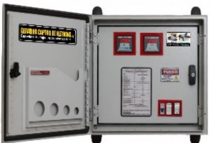 Someone sent
me a link to a Brazilian
company - inventors Barbosa and Leal - that is evidently offering a
commercial unit
- or,
trying to... their machines were seized. As
usual not knowing the source of the energy, they say it captures
"Earth electrons", but it doubtless is collecting lambda rays which get
the
electrons moving. (which is pretty similar in principle to the
photons moving the
electrons in a solar collector.) They look very well made. And I
appreciate the energies being kept inside a box! Their units make 6, 40
and 282 kilowatts.
Someone sent
me a link to a Brazilian
company - inventors Barbosa and Leal - that is evidently offering a
commercial unit
- or,
trying to... their machines were seized. As
usual not knowing the source of the energy, they say it captures
"Earth electrons", but it doubtless is collecting lambda rays which get
the
electrons moving. (which is pretty similar in principle to the
photons moving the
electrons in a solar collector.) They look very well made. And I
appreciate the energies being kept inside a box! Their units make 6, 40
and 282 kilowatts.
http://www.libertariannews.org/2013/11/05/brazilian-firm-goes-to-market-with-free-energy-generator-capable-of-powering-two-average-size-houses/
(English news article)
http://energiauniversal.eco.br/
(Portuguese)
Also, on youtube there's a video of the inventors demonstrating the
units (Portuguese) and the news article (English) mentioned above. (I
don't have the links handy.)
On the 11th I wrote for more information. That evening I
even considered buying one of their machines, but they were quite
costly. The next day I looked up their
first patent. The actual workings weren't that different from some
others, but there were a couple of odd things. I can try a couple of
their twists in my experiments and see how they work out. I have
received no reply. They are running into flak, to say the least. I
fear for their safety and liberty.
The Free Energy Book
In my searching I ran into a link to an updated web
copy of the free energy book that I already have, which has added the
Brazilian devices, with some explanations of the patents, to the many
other circuits that presumably capture lambda rays. I can only
wince at the descriptions of "capturing electrons from the Earth" or
from the air "by induction" through essentially unconnected wires.
Obviously the energy is coming from lambda rays. In fact, I think the
'unconnected' "electron capturing" wires are
why they're getting such great results (I assume that they
actually are): http://www.free-energy-info.tuks.nl/Chapt3.html
In fact, I suspect that Tesla's needle point serves the
same
function and will work better than the
loop of ground wire around the collection wire. I think that's a
'connection' that'll improve the performance. Now... would the gold be
limited to the needle point, or should the whole collection wire loop
be gold? Gold at the point where the lambda rays interact with matter
(wherever that is) could be a big boost.
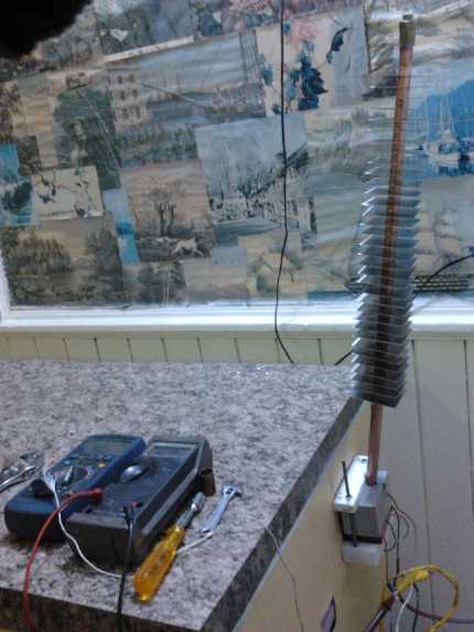
Initial Test
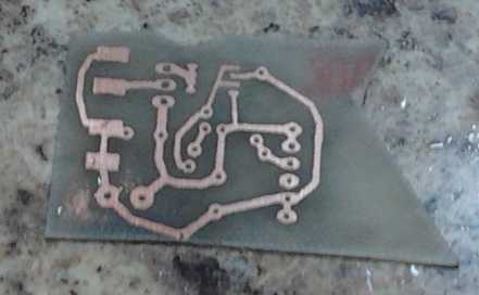 The etched PCB
 After
designing and making the new PC board on the 18th,
on the 19th I hooked up the wires and tried it out. I
hooked up a power supply, a signal generator (TTL level square wave),
an oscilloscope on the control coil, and a 400W electric heater (36
ohms) with a
voltmeter across it set to AC. It initially drew no appreciable
current, but if the drive waveform was on at all, it drew 5 amps almost
regardless of signal frequency (ouch!), at only about 7 volts supply
(35W - the
supply was running current limited). I tried various signal frequencies
from 1KHz to 1MHz. Nothing seemed to happen. Coil voltages went up to
about 100 volts, but dropped off rapidly when the signal went above
100KHz or so.
After
designing and making the new PC board on the 18th,
on the 19th I hooked up the wires and tried it out. I
hooked up a power supply, a signal generator (TTL level square wave),
an oscilloscope on the control coil, and a 400W electric heater (36
ohms) with a
voltmeter across it set to AC. It initially drew no appreciable
current, but if the drive waveform was on at all, it drew 5 amps almost
regardless of signal frequency (ouch!), at only about 7 volts supply
(35W - the
supply was running current limited). I tried various signal frequencies
from 1KHz to 1MHz. Nothing seemed to happen. Coil voltages went up to
about 100 volts, but dropped off rapidly when the signal went above
100KHz or so.
Roughly following a design of the Brazilian device, I had
clipped an alligator clip leed onto one side of the collector coil. The
coil wire was insulated so there was no electrical connection. Normal
circuit design would say that little effect should be expected almost
regardless of where the other end was connected. The other end
went to "ground" on power supply. But the DC coil supply was
ungrounded, floating.
I now moved the connected end from "ground" to "minus" on
the power supply. This time, when I turned it on and swept the signal
frequency up, suddenly the whole assembly seemed to start squealing at
the signal frequncy, and the heater voltage for the first time came to
life, reading 32 volts.
After two tests of a couple of seconds with
about the same results, the power transistor feeding the coil went up
in smoke. I had definitely been driving it to its limits,
according to its datasheets, and beyond as it heated up.
It was an amazing change -- from reconnecting a wire with
no
actual connection at the other end! When I calculated the power to the
heater at 32 volts, it was just 28W, and I was feeding the coil driving
circuit with 35W, so it can't be claimed that I'd got more power out
than in. But it had been using 35W in all the previous tests as well -
and there was no way to couple that input energy to the output. So
there seemed to be some extra energy arriving from
somewhere. It seemed pretty promising for a first try.
I didn't have a chance to replace the transistor, use more
turns of the coil to lower the current, change the "unconnected"
aligator clip to a needle point, and try again before I got the flu. In
a way, the signal generator is a problem, because I really want to
drive the coil with a narrow pulse rather than a square wave. The pulse
would have the same sharp transitions and the driver would use far less
power. Perhaps a 555 timer as a pulse generator would be simpler than
wiring and programming a microcontroller.
On Christmas day I drew by hand an overall circuit diagram
of the
lambda collector for version 3:
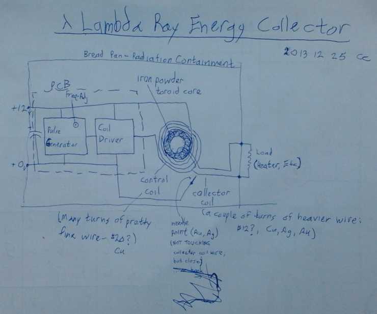 I think the scribbled out 'hook' ground wire
with sharp point, wrapped
I think the scribbled out 'hook' ground wire
with sharp point, wrapped
around the collector coil wire at one end of the coil, is probably best.
Winding the collector coil as a turn or two around the outside of the
donut,
and the control coil through the center of the toroid, opposite to the
arrangement shown, would probably be better.
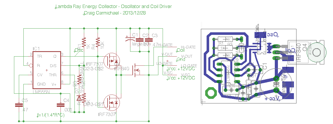
On the 26th I looked up 555 timer circuits and found the
one I'd used for motor controller PWM. I modified that to generate
narrow pulses that wouldn't use so much current and designed a circuit
board complete with all the electronics in Eagle PCB. (what a great PCB
CAD program!) On the 27th I tidied up the layout and made the board. On
the 28th I put the components on the board and started wiring it all
together, but it was a considerable job and I didn't finish before
having to do other things.
 Version 3 with built-in pulse generator
One important assembly job was to make a top cover for the
bread pan I had elected to use as an enclosure. I strongly suspect that
dangerous radiations are released in all this process, and that there
should be a metal shield between the collector unit and any human being
in the vicinity. (In the 'version 2' tests I had set it up high and
ducked below it.) After all, the process starts with rays
shorter than
dangerous gamma rays and x-rays, and descending down the spectrum, even
infra-red or "microwaves" (centimetric rays) can cook flesh. I used a
6" x 12" piece of #28 nickel-brass and folded the edges to fit it over
the
top of the bread pan. At the back end I cut a piece to fold up as a gap
for wires to enter.
I made it positive ground for the 12 volt supply in order
to connect the mosfet drain electrically to the bread pan. After
sorting out a few wiring problems, it still didn't seem to collect any
energy. But I didn't have time to continue, and there's still coil
driving oddities to figure out and then more things to try.
Magnet
Machines
In attempting to look up designs for radiant energy
collectors, I found a site, www.magnetmotorhojo.com
, where they offered a book with detailed instructions for making
Howard Johnson's patented magnet machine for about 50$. Since this has
been said to work, I decided to order the book. I might have eventually
reinvented this wheel, but if others already knew how to make one,
probably better than what I'd have come up with, why not use it?
Once I had paid, the book
was in PDF for immediate download, and there were four instructional
videos on turning a regular motor into a magnet machine.
If the book convinced me of one thing, it was that
Johnson's design probably worked with no arms or cams, just magnets
fixed on a rotor and fixed on a stator. The main trouble was, probably
for
everyone that wanted to make one, that the rotor magnets were a weird
shape, something like a cylinder having a "crescent moon" cross
section. I've never seen such a shape for sale, so unless you can make
your own magnets, the otherwise simple design seemed rather unmakable.
Could such a simple design actually work? Johnson did
get a patent on it. As I hear the story (second hand), the patent
office said they would give him one only if his machine was still
running in their office after a prolonged period - at least weeks if
not months. It was. It ran for a decade in the patent office until the
magnets weakened too much. There has been talk that the machine was
powered by the weakening of the magnets. But a supermagnet (again
according to what I hear) is magnetized by a pulse of current through a
coil, to whit, a million amps for a microsecond: one amp-second of
energy. That that energy could, by its 'dissipation', run a mechanical
unit for weeks, months and years before expiring is harder to believe
than the explanation in the patent. And there are magnet machines and
rumours of magnet machines that seem to have no moving parts besides
their rotor.
I decided to order some small, thin magnets to experiment
with. The big, thick ones I've been using (Electric Hubcap Motor
magnets) have such a great depth of field it's hard to move them
mechanically in and out of magnetic interaction. I'm still not entirely
convinced it can be done without that. Johnson's machine might have
attained some mechanical resonance, "slop" or "play" in the mechanism,
that moved his magnets fractionally up and down, or twisted them, at
just the right moments.
Troy Reed's first giant motor on youtube had some sort of
"crank rods", but his second, much more compact one, didn't appear to.
I
now intend to find out, one way or another!
A first stop was to check out chapter one of The Free
Energy Book again (http://www.free-energy-info.tuks.nl/,
where
many
designs
are
shown. The author says it's very hard to get a magnet
machine to run without moving parts but that it can be done. Evidently
it's much easier to get one with moving parts going. Could I be right
about the "play" and "resonance"? Perhaps the author was right that
ones with a coil to push the magnet through sticky spots is a simpler
choice, and that the coils can be energized with electricity generated
by the unit itself. Or perhaps it really is true that no energy can be
gained -- but there are an awful lot of stories of successful units.
On the other hand, a diagonal arrangement of magnets seems
somewhat promising to create a 360° imbalance in one direction. I
ran across this little diagram somewhere. But again it uses magnets
which ain't the common rectangle, cylinder or wedge shapes.
http://www.TurquoiseEnergy.com
Victoria BC