Turquoise
Energy Ltd. News #72
(January 2014)
Victoria BC
by Craig Carmichael - posted February 4th, 2014
www.TurquoiseEnergy.com
= www.ElectricCaik.com
= www.ElectricHubcap.com
= www.ElectricWeel.com
Highlights:
Self-Turning Magnet Motor Experiments (see Month in Brief,
Electricity Generating)
Month In Brief
(Project Summaries)
In
Passing
(Miscellaneous
topics, editorial comments & opinionated rants)
Electric Transport - Electric
Hubcap Motor Systems
* Huge Electric Weel Motor & Generator Construction (and
maybe
other large sizes): Plywood?
* Another in-wheel motor (adding unsprung weight to wheels) in the news
Other "Green" Electric Equipment Projects
* Thermoelectric Fridge Repair: graphite gaskets open new
possibilities.
* Improved Performance Peltier Modules are (probably) coming!
* Large flat panel LED lights to replace fluorescent fixtures
Electricity Generating
* Magnet Motors: Johnson, Reed, Yildiz, Brady (demonstrated to
thousands), V-gate ramp... spiral ramp.
* Magnetic "shielding": attraction by iron counters like-poles
repulsion to create magnetic imbalance.
* With "shielding", rotor *seems* to turn more readily & spin
longer in one direction than the other. Maybe.
* Alternative shield?: repulsion by bismuth would counter opposite
poles attraction.
* If all else fails, one electromagnet coil pulsed briefly will ensure
rotation, uses less energy than can be produced.
Electricity Storage - Turquoise
(NiMn) Battery Project etc.
* NiMn cell next try: inconclusive so far.
* Graphite Felt to improve electrode conductivity &
chemical %
utilization
* Pulse Chargers for lead-acids: limited success.
No Project Reports on:
Lambda Ray Collector, Torque converter (sigh!), DSSC
solar cells (abandoned), LED Lighting, Pulsejet steel
plate cutter, CNC Gardening/Farming Machine (sigh, maybe summer 2014?),
Woodstove/Thermal Electricity Generator (will probably abandon),
evacuated tube heat radiators, individual EV
battery monitor (will probably cancel).
Newsletters Index/Highlights: http://www.TurquoiseEnergy.com/news/index.html
Construction Manuals and information:
- Electric Hubcap Family Motors - Turquoise Motor Controllers -
Ersatz 'powder coating' home process for
protecting/painting metal
- Preliminary Ni-Mn Battery Making book
Products Catalog:
- Electric Hubcap 4.6KW BLDC Pancake Motor Kit
- Electric
Caik
3KW BLDC Pancake Motor Kit
- NiMH Handy Battery Sticks, 12v battery trays & Dry
Cells (cheapest NiMH
prices in Victoria BC)
- LED Light Fixtures
(Will accept BITCOIN digital currency)
...all at: http://www.TurquoiseEnergy.com/
(orders: e-mail craig@saers.com)
January in Brief
Magnet Motors
 I heard of
some magnet
motors - tho I believe designs having electromagnetic coils -
generating
power at levels akin to lambda ray radiant energy collectors: kilowatts
or even tens of kilowatts. My order
of magnets
arrived on the 7th, and I decided I'd try some experiments. These
seemed promising, and I decided to try making a magnet motor. It was
time consuming to set up G-Code programs for the CNC drill router. In
perplexing contrast to the experiments, they didn't work at all when
made into
rotors. Nada!
I heard of
some magnet
motors - tho I believe designs having electromagnetic coils -
generating
power at levels akin to lambda ray radiant energy collectors: kilowatts
or even tens of kilowatts. My order
of magnets
arrived on the 7th, and I decided I'd try some experiments. These
seemed promising, and I decided to try making a magnet motor. It was
time consuming to set up G-Code programs for the CNC drill router. In
perplexing contrast to the experiments, they didn't work at all when
made into
rotors. Nada!
On the 19th I browsed youtube and saw videos of Mike
Brady's
Perendev magnet motor. Several other videos showed some Perendev motor
copies
which
mostly didn't work. Just one video explained the magnetic workings. The
sideways magnetized cylindrical magnets probably explained some
of the failures to copy the original design: who would ever suspect
that
cylindrical magnets weren't magnetized end to end? It was
almost what I'd been doing, with the magnetic twist to the stator side
and some careful spacing relationships. It seemed like an excellent
bet.
I could make rotor-stator pairs for the triple pair machines with the
CNC router.
Then I
came up with some better(?) ideas of my own incorporating more things -
spiral layout, and magnetic shielding, iron pieces that seemed to
maximize the
difference between clockwise and counter-clockwise rotational forces. I
worked up G-Code for the CNC router and routed the rotors and stators
from HDPE on the 25th. The spiral was a good bet because such a unit will
propel around one turn, and if turning stalled at the end/start of the
spiral and it simply couldn't be made to work, a single coil could be
placed there and briefly energized each turn to get it over the reverse
thrust spot. Such coils evidently still use less electricity than the
unit can generate. Maybe I'm a purist wanting it to run on permanent
magnets only. Howard Johnson, Mike Brady, Muammar Yildiz and others
have demonstrated such machines to hundreds if not thousands of people.
They also all spent many years getting workable models.
I didn't work on my lambda ray collector. But one day I saw someone
present what would have been a lambda ray collector, on TV on Dragon's
Den. One of the investor panel said, "If the technology works, it's
a deal!" If events from the Brazilian invention and patents are any
indication, the technology and unit production may be the least of
their problems. I hope it works out. The publicity with likely future
follow-up from Dragon's Den may make it hard to pull some overt crime
on them, but there are still many dirty "business" tactics that can be
pulled by criminals with billions of dollars at their disposal and
politicians in their pockets to ensure failure of the enterprise.
Car Repairs & EV Show
Considerable time was spent on car repairs to both
the Tercel and the electric Mazda extending over some days. After I was
done, the Tercel driver's side window jumped off its rails again, and
the Mazda windshield washer pump (fixed last spring) had quit working
again. The pump motor body was rusted right through and I could see
copper
windings inside it.
I have the
feeling both cars are approaching their reasonable life limit with more
things breaking as soon as something else is fixed. Still other needed
jobs were being put off. Hence putting the magnet motor designs to
CNC code towards the end of the month proceeded very slowly.
As part of this I went to the big auto wrecker yard I
usually went to for a part, and I had the thought that having failed
to make a usable variable torque converter in all this time, I might
pick up a manual transmission for the Chev Sprint and do a "regular"
electric conversion on it, knowing they had some Sprints lying around
there. It was a shock to find the whole auto wrecker yard and all its
piles of junked cars was gone, replaced by a welding yard and some sort
of big
"industrial park" being built!
An electric car show was spotlighted at a local hockey
game on January 31st, organized by the Victoria Nissan Leaf Club.
Originally I was supposed to display the electric RX7, but when I
arrived I was told too many electric cars had already shown up and
there was no more room. This was too bad. It's no beauty compared to
all those new models, but it would have been the only converted car in
the show.
PbPb Pulse Charging
I finally made a pulse charger for lead acid batteries... and then I
bought a commercial one. Either of them seemed to charge up a battery
I've had sitting here for months that would only hold 10 volts and
couldn't be charged up with a 'regular' charger. (It would start to
charge and reach 12v, but would soon start drawing more current and
dropping down again.) But they didn't seem
to add any amp-hours to batteries that had low capacities. When I made
mine I had no idea what frequency of pulses to use and couldn't find
any info on the web - part of the reason for buying one after all. I
made it about 600 Hz with a narrow pulse. The
commercial one turned out to be 40-50 KHz. I'd probably have titled
that "supersonic charging" rather than "pulse charging".
I also determined as part of this experimentation that
some "old" batteries I'd "renewed" when I got the Mazda hadn't been
sulfated up enough to renew. They didn't have enough sulfate on the
plates to reconstitute the acid or sodium bisulfate. I knew the Battery
Doctor thought at least one of them was a good battery he'd almost have
sold as it was. (I bought them as scrap.) I should have used them as
they were until they wouldn't hold charge, rather than assuming the
recycling pile was all "depleted", ie badly sulfated up, batteries.
Graphite Felt for Ni-Mn Cells
Someone mentioned this substance, which I had never heard
of before, to me in an e-mail. I made some inquiries on line. It sounds
ideal: if one can shake the electrode powders into the spaces in the
felt and then compact the works into a briquette, it should be highly
conductive throughout. This would doubtless greatly improve current
drive and percent utilization of the active chemicals.
Green Energy Night
On the 27th I sent an e-mail to the Victora Makerspace
list offering to lead a regular "Green Energy Night" for building green
energy products. My original plan had been to offer a course in Electric
Hubcap
Motor Making. When I had proposed that to one of those who
run the makerspace, he had suggested he wanted one to use as a wind
plant generator. Since it was closely related to windplant generator
design, but not suitable as made, this immediately put a split in the
program, and after some time and thought I came up with the Energy
Night idea. I'm joining the club and making contacts. I'll put up a
list of projects I'm capable of giving directions for - and other more
speculative projects - and prospective builders can select anything
from that list.
Peltier Modules Refrigerator & Heat Pumping - graphite gaskets -
improved module performance
The fridge performed rather poorly after I out tried the
evacuated pipe in December, and then put it back together again as it
was. It drew
less current and had to stay on most of the time instead of 'just' 2/3
or so. It only got down to 2°C instead of 0 or -1 if left running.
I thought the peltier modules must be making poor thermal connection
somewhere. I
finally redid it on the 28th, cleaning everything carefully and moving
the
clamping bolts to better positions by drilling new threaded holes in
the heatsink. I put it together and tried different things, to no
avail. It turned out the real problem was that the larger Peltier
module had a small crack in one corner and was only 'sort of' working.
I replaced it.
As a part of this, while it was apart and during
installation I took video footage to do a "Peltier Fridge Part 2" video.
Also, I tried graphite gasket material (which I was using
for the Ni-Mn battery current collectors) in place of icky silicone
heatsink grease. That worked well. When a piece was placed on the
copper bar to the ice tray, the cold of the bar could be felt
immediately, right through the graphite.
This has an important benefit: providing a slight cushion.
Thus the Peltier mounting surfaces don't have to be so perfectly flat
and clear, with multiple Peltier module thicknesses micrometrically
even. I probably wouldn't have cracked the first peltier unit if it'd
had graphite gasket. Suddenly I could see the fat copper pipes I
flattened many months ago for a Peltier heat pump space heater as being
flat enough to use, even tho not micrometer perfect.
Also during the month I read that improved "nano layered"
peltier
modules have been invented. They are probably coming once manufacturing
techniques have been
worked out. (See "Other Green Electricity Projects", below.) These
would then simply replace the existing type and make whatever heat
pumping equipment they were attached to around 3 times more effective -
drawing 1/3 the current, pumping 3 times as much heat, or any desired
point between those. The fridge could be 20 watts instead of 45
and run just 1/3 of the time, mostly on solar power per the original
plan. Such improved modules would probably make compressor &
refrigerant heat pumping
obsolete for most home scale applications. And thermoelectric heat
pumping projects
and products will be an excellent area to develop.
Making a thermoelectric heat pump, planned now for a year,
might be a good project for February. After the last few months, it
would be nice to do something that is highly likely at least to work as
built, and then work on performance measurements and improvements.
In Passing
(Miscellaneous topics, editorial comments & opinionated rants)
Since 2008 there have been qualified people saying
the financial system is imploding, along with the economy, and some
have spoken of the collapse of the "world population bubble" that will
result
when the crisis hits. Most have been reluctant to predict actual events
or dates since it's basically a matter of when people lose confidence
in the tottering, crooked system and it's so hard to say when that
might happen or what the final, fatal trigger will be. But thoughtful
opinion seems to agree
it's not a decade off but much more imminent. Now some of them are
talking with more conviction about it coming this year, or 2015 at the
latest. Warnings are starting to come even from people currently in
various positions of authority. These are played down or ignored by the
mainstream news, most of which is now owned by or beholden to the
corrupt.
In some ways, going around town everything seems perfectly
"normal", but in others, and in various economic statistics, one starts
to feel the main event can't be held off by money printing and market
manipulations too much longer. Average incomes continue dropping as
prices
rise, 20% of Americans are on food stamps, British and European people
are already starving, and global shipping, already down by 2/3 from
a decade ago, has fallen still farther after a dismal Christmas
shopping season. Stores are trying to unload excess inventory even at
1/2 price and a number of store chains have folded. Even Wallmart isn't
doing well. Much of the middle class has been systematically stripped
of their wealth and the majority have no money, or even credit left, to
buy goods with. Politicians on all levels seem to be in it only for the
money themselves and do little that's actually helpful or corrective.
Here in Victoria BC there
are empty commercial buildings for sale or rent almost wherever you
look, and yet against almost the whole community our unelected district
politicians are unflinchingly bent on bankrupting the city with a huge
sewage treatment project that most people feel is wholly unnecessary
and will create serious environmental as well as financial problems,
and completely disregarding a dozen or more valuable and needed public
works that ought to be undertaken, which all put together make a
smaller monetary total. One gets the impression that they're bribed by
the banksters, just like in the Jefferson, Alabama sewage treatment
fiasco.
Electric
Hubcap Motor Systems - Electric Transport
Another In-Wheel
Motor
Unsprung weight is a problem in automotive engineering.
Vehicle handling deteriorates as it rises. With heavy wheels, a small
car starts to feel like a truck. The basic premise of a "wheel motor"
is in conflict with this basic design consideration. If one is going to
make a motor to directly drive a wheel of a new vehicle, a better idea
is that it should be mounted on the end of a drive shaft with CV or
universal joints so that only 1/2 the driveshaft may be considered
"unsprung" and not the whole motor.
The Electric Hubcap system concept is a bit of an oddball.
In order to work with existing vehicles without modifying them, it is
placed outside of the wheel. It is mounted from the axle or brake drum
housing by two small square tubes which, being over a foot long and
bent in a "U", have some spring to them. In concept the motor drives an
in-line variable torque converter, which is connected to the wheel
through a flexible coupling. Thus the motor is at least somewhat free
to bounce up and down compared with the wheel, reducing its impact on
handling over a motor built into the wheel.
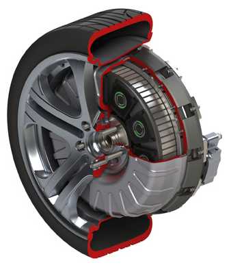
That doesn't stop people from making wheel motors. The
news article is copied in abridged form below. It doesn't mention
handling, nor does the unit appear to provide for mechanical brakes.
The motor ratings are as usual amazing. One suspects it would need
liquid cooling.
A new set of wheels is on the way
 Protean Electric has teamed up with a major automobile
manufacturer
to develop its novel in-wheel
electric
motor
technology, with the intent of using it in a
production car.
Protean Electric has teamed up with a major automobile
manufacturer
to develop its novel in-wheel
electric
motor
technology, with the intent of using it in a
production car.
The Michigan-based company is working with FAW-Volkswagen, a Chinese
automaker part-owned by VW Group, to integrate the system into a
battery-powered Bora sedan demonstration vehicle.
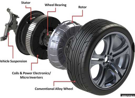
Protean says that installing its motors directly at the wheel
eliminates the need for driveshafts and other
components, while offering better control of the power delivery to each
wheel.
The Bora is being developed as a rear-wheel-drive vehicle with one
motor at each wheel. The Protean motors feature an inside-out design,
with the stator on the inside and rotor on the outside, and are bolted
directly to the wheels, where they deliver 100 hp and 739 lb-ft of
torque each. Each motor should cost about $1,500 when
series production begins.
Electric Weel
Motor & Generator Construction: Plywood!
 My Electric
Weel motor project sat idle for a
long time. Coastal Geoscience Research Corporation wanted a
12KW low RPM generator for an experimental hydro power project. The Weel
fit this profile.
My Electric
Weel motor project sat idle for a
long time. Coastal Geoscience Research Corporation wanted a
12KW low RPM generator for an experimental hydro power project. The Weel
fit this profile.
Having changed motor constructions considerably with Electric
Hubcap experience since
starting on the Weel,
especially the motor cases, I had ideas that weren't compatible with
the way I'd been doing it. And because there were no "buttons" to hold
the coil centers, I wasn't confident in the mechanical strength to use
it for a transport motor with road bumps and sudden dynamic changes in
loads. But as a generator, it would be under less transient stresses.
I sold the unassembled unit and said I'd help put it
together. On the 9th and 10th, we wound some coils to make up for the
ones I'd used in the Electric Caik motor. As we did this, I
considered the construction.... and started coming up with a wholly new
and better idea.
Metal could be used for the top piece, the rotor end
cover, but it would have to be fairly thick to be stiff enough, and
that would be heavy. Then I thought of plywood. 3/4" plywood - or
perhaps even 1" - would be pretty stiff and lighter. And if it was left
square instead of cut into a circle, it would have corners sticking out
to attach mounting bolts to.
Then we considered the sides. The customer ran into the
same problems I had trying to find a big plastic "culvert pipe" ring.
They just aren't sold in 6" lengths at the exact large diameters
wanted. While he was looking, I thought
again of plywood: an octagon of carefully cut & fitted pieces,
which could be screwed and glued to the top piece to make a good stiff
"top hat" unit.
Continuing with the theme, how about wooden dowels for
coil center 'buttons'? These could be glued and screwed to the plywood.
That would answer the concerns about transient loads - it would be
robust enough for a vehicle motor.
The bottom end was a ring of 1/4" plywood bolted to a big
metal center that didn't quite come out to where it would cause
magnetic interference. But 1/4" was needlessly thin. Only the center
ring needed to be thin, so the magnets could come close to the coils. A
thicker piece of plywood could have done the whole job. I came up with
the idea to bolt the ring to such a thick piece in addition to the
metal center. This would be the center and also extend outward beyond
the ring so the sides would butt up against it when the top was put on.
The shaft would stick out the bottom, making that the 'business end' of
the assembly.
For future machines of this size, I'd probably just go
with 1" plywood and skip the big metal center.
Of course, all these wooden pieces would be coated with
polypropylene-epoxy and painted with polyurethane paint. Such thick
wooden construction should safely stop any magnets that fly off the
rotor, and it lends itself well to home production. And it's probably
the lightest reasonable construction, other - perhaps - than PP-epoxy
molded parts.
The main custom pieces would then be the bearing holding
end washers and the big magnet rotor.
Suddenly, the "entry barrier" to making one-off huge Electric
Weel machines has been slashed. No longer will it be necessary to
make molds to stuff full of PP-epoxy. The logical intermediate size, 18
coils and 24 magnets on an 18" rotor, could also easily be made at will
with a wooden case.
Around mid month, the client had to fly off for a couple
of weeks. I wanted to get the case prepared - at least the plywood
pieces all sized and cut - but really had no time for it. It was the
height to make the sides that needed considerable figuring, some of
which was best done after further assembly. In my head I planned out
the CNC routering program to make all the holes and trace the lines.
Other Green Electricity Projects
Peltier Modules Refrigerator Repair
The fridge performed rather poorly after I out tried the
evacuated pipe in December, and then put it back together again as it
had been. It drew
less current and had to stay on most of the time instead of 'just' 2/3
or so to stay cold. It only got down to 2°C instead of 0 or -1 if
left running. I thought it was a good demonstration just how much
difference 'good' thermal
connections with the peltiers made versus 'mediocre' connections. I
redid it on the 28th, cleaning everything carefully and moving the
clamping bolts to better positions by drilling new threaded holes in
the heatsink. I put it together without heat sink grease to see how
that would work out.
As a part of this, while it was apart and during
installation I took
some video footage to do a "Peltier Fridge Part 2" video.
It didn't seem terribly effective. I unclamped the
peltiers and this time I put in pieces of thin flexible graphite gasket
material. The cold from the copper bar could immediately be felt right
through the graphite, but when it was back together I didn't think the
currents were as high as they should be, so I took it apart again and
used silicone heat sink grease instead. But that seemed to work even
more poorly, currents dropping from about 2.8 amps to under 2.6.
On the 30th I decided to give the graphite a try again.
The heat transfer of the graphite seemed quite good. But it performed
no better. I decided to try new
Peltier modules - perhaps I had damaged one in all the clamping,
without having it quit entirely. Sure enough, I found a small crack in
one corner of the larger one. It must have cracked when I did the test,
or right afterward when restoring the original setup. I replaced it and
the current went up to where it was expected to be, around 3.6 amps. So
much for thinking the problem was "mediocre thermal connections"!
It was something of an exercise in futility except the
graphite seems like a good improvement. I'm not much of a fan of icky
silicone grease. There seemed to be about 2 or 3° drop from the
peltier
warm side to the heatsink, which was at worst not much more than usual.
There's thinner graphite gasket material, too, .005" or .010" instead
of my .015". And the slight cushion of the graphite on both faces will
reduce effects of any tiny bit of trapped grit and also the chance of
cracking another Peltier module. And I got video footage for an
"update" to the first Peltier Fridge video.
Improved Peltier
Modules... are
probably coming
Some time ago, I did some experiments with magnetic heat
pumping using gadolinium and related elements. It was interesting and I
think I was on a good track using layers of gadolinium powder attracted
and lifted up by the same magnetism that heated it, between layers of
copper foil, to pump heat upward by having a supermagnet running around
and passing the assembly - or perhaps by switching an electromagnet on
and off. But it then occurred to me that if anyone ever came up
with a significantly improved peltier module, then small scale heat
pumping
with moving parts, either compressors or magnetic, would be of much
less interest, especially for small scale units.
Early in the month, I found "Thermoelectric Materials"
on Wikipedia. It seemed people already had the best thermocouple
elements pretty well pegged out. Bismuth was at one end of the scale,
and tellurium was second from the other, so it may be of little
surprise that doped bismuth telluride (Bi2Te3) has been the material of
choice. This yields a thermoelectric effect ("ZT") of .8 to 1,
according to the article.
The one element that was better then tellurium was
selenium. I don't know why bismuth selenide (Bi2Se3) isn't the usual
choice - telluride may have some better properties around room and
typical refrigeration temperatures. But it seems that a new
construction
of alternating nano-layers of bismuth telluride and bismuth selenide
blocks thermal conductance (insulates, so the heat doesn't readily
transfer across
between the cold and hot sides) while allowing electrical conductance,
making for a higher "ZT" of up to around 2.4. Other materials and
construction techniques of interest for improving performance seem to
be under investigation.
If - and I expect when - practical production methods for
such Peltier modules are worked out, they would permit more practical
and cost effective 'solid state' refrigerators and one-room or EV car
scale heat
pumps with higher coefficients of performance. There would be no
changes to the physical designs I've been planning - just better
performance. The improved peltier modules will simply replace the
existing type and make whatever heat pumping equipment they're attached
to around 3 times as efficient - drawing 1/3 the current, pumping 3
times as much heat, or any desired compromise between those points. The
fridge could be 20 watts instead of 45 and run just 1/3 of the time,
mostly on solar power during the day per the original plan.
That would probably make compressor & refrigerant heat
pumping obsolete for most home scale applications. And developing
magnetic heat pumping rather pointless. Abandoning magnetic heat
pumping in favor of peltier modules was probably a good choice.
Large Flat LED
Light Panels Replace Fluorescent Tube Fixtures
Jim Harrington ordered from China some 300x300mm and
300x600mm flat rectangular LED light "panels", as well as some flat
circular ones. I bought one of the large ones from him at cost for
around 75$. Jim said when he put one of these above his assembly area
he felt he had been working in the dark until then.
I put this one foot by two foot, 30 watt, 4700 K panel on
my kitchen ceiling. It was so bright every spec of dirt on the floor
glowed and I had to wash the neglected floor. It is much brighter than
the 9 watts of Cree emitters I removed and much brighter than the 80
watt fluorescent I had before. In fact, it provides an astounding
amount of light for 30 watts even for an LED light.

Incredibly bright LED light panel.
The cupboards are lit up like it was daylight, with no flash.
That was a 40 volt unit. It was so bright I considered
getting a smaller one, so I then bought a 300x300mm, 12 volt, 17 watt
one (made by a different company) from him for 50$. It was a more
orange or pinkish color and nowhere near half as bright. It certainly
wasn't bright enough for the kitchen and I was disappointed. Its main
redeeming feature is that it can be run from the 12 volt solar power
system, or a 12V power adapter.
But I'm thinking I might try making similar units
specifically for solar power systems, that can run off about 11 to 15
volts. Maybe dimmable.
Electricity (Energy) Production
Magnet
Machines
I heard that some self turning magnet motors that aren't
huge can generate kilowatts. That rivals the lambda ray collectors. If
this can in fact be accomplished, they're considerably more useful than
if they only make fifty or a hundred watts. The torque is
probably not very high, but the RPM s seem to be considerable, eg, 2600
to
3600 RPM with no load - and power equals torque times speed.
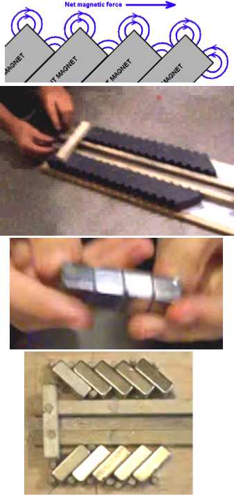
My magnet order arrived on the 7th. The ideas presented in
Free Energy Info, Chapter 1,
under the heading Simple Permanent Magnet Motors seemed
to be the most promising. The way the moving magnet shot out the end of
the array in the demos linked to (on Youtube), done by a couple of
boys, was impressive. The skeptic would assume it takes as much energy
to feed the magnet into the magnetic "chute" as the chute propels it
by. But it didn't look like it. If the assumption that it doesn't was
true, what remained was to translate the straight line accelerator to
circular rotors and stators.
There could either be multiple chutes and long moving
magnets, or complete circles of magnets on the stator. If it needed to
be multiple chutes, these could probably be arranged so that two
magnets in chutes could
pull the next magnet into a chute before the first one exited the first
chute. It might actually need a locking pin to prevent it from
rotating, as was also likely with complete circles. But even with one
chute and one moving magnet, if it was spun
up by hand fast enough, it should continue rotating and accelerate to
some equilibrium.
Working principles and demos from
Simple Permanent Magnet Motors
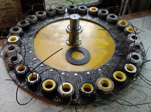
I decided on an axial flux
machine rather than the radial flux idea of the author. The reason is
that with radial flux, the magnets would have to abut at angles to each
other to follow the curve instead of touching faces. That might be
tricky. It's hard enough to get powerful magnets to stay in place on
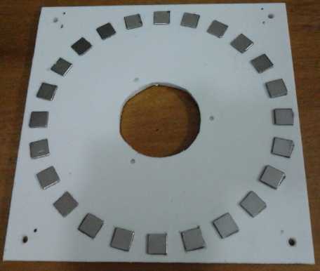
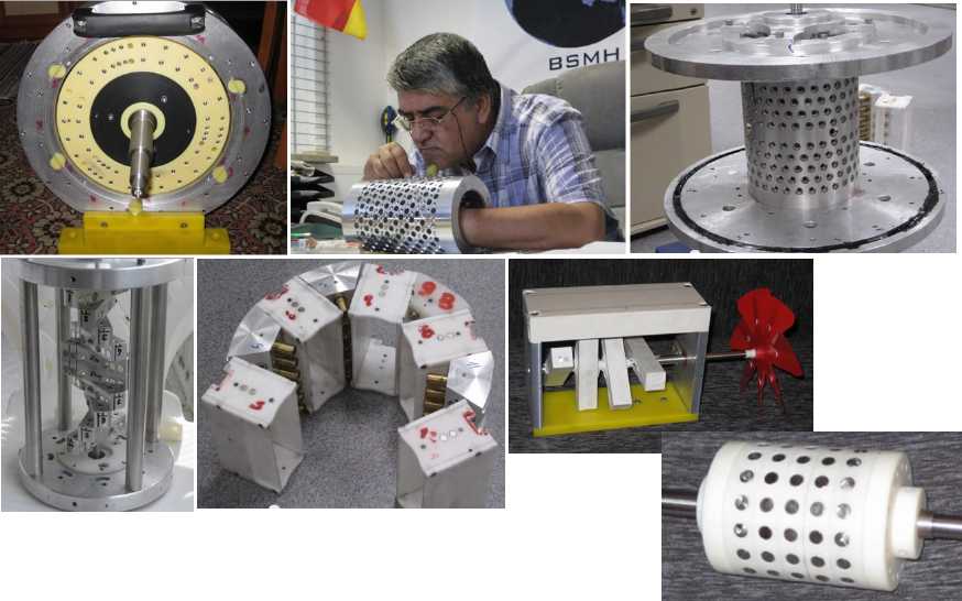
any diagonal (see the many dowel pegs in the bottom image).
Furthermore, the inner and outer sides couldn't be made symmetrical.
(Hmm... could non-symmetry be an advantage?) The author also claimed
that many people had had a hard time when they tried turning the linear
chutes into circular ones with one inside and one outside.
With axial flux, the
magnet faces could touch as in the linear chute illustrations, but each
magnet would
be slightly angled - in the other direction - for the row to follow the
curve.
Complete circles down and up of the same diameter should be no problen
to make. Furthermore, the long moving rotor magnet could be straight
instead of
curved with minimal magnetic distortion and no chance of jamming if the
curved path was too narrow. And the distances between the upper and
lower plates and the rotor spacings could be easily adjusted - a
priceless advantage in an design where "workable", much less "optimal"
spacings aren't known yet.
If there were to be individual chutes, I wanted long ones,
longer than the
gaps between chutes, so that two magnets would be, eg, 1/3 and 2/3 of
the way through, pulling, when the next one magnet was to be pulled
into a chute.
I only bought 50 magnets, 25
per row, placing what I now realize is a pretty strict limit on chutes
and lengths, eg, 2 chutes of 12 on each side. They would be even more
sparse for doing two complete circles. And I only got 8 half inch cube
magnets. Doubling or tripling the order would have been good. Hopefully
these will be
sufficient for a demo.
So, a double-plate stator would have a rotor with long
magnets spinning between its
upper and lower parallel planes of continuous or relatively long angled
magnet
"chutes". There was also the possibility of multiple stators and rotors
in a "layer cake" to increase the torque and power, but I'll leave idea
that for the moment and keep it simple, especially as there's hardly
enough magnets for one 'layer'.
The next question was construction materials, methods, and
dimensions. I decided the top and bottom stator plates could also be
the top and bottom covers, with the magnet chutes on the inside faces.
The centers would have holes for ball bearings for a 1/2" shaft. The
outside diameter would be a little larger than the magnets & rotor
diameter so an outside perimeter cover could be placed between the two
plates and clamped in by bolts.
 After thinking
about these things, I realized I wasn't
ready to make any circular unit until I had made some simpler linear
chutes of my own and launched a few magnets through them, and
determined what sort of dimensions, spacings and magnet angles worked
reasonably well with the magnets I had acquired.
After thinking
about these things, I realized I wasn't
ready to make any circular unit until I had made some simpler linear
chutes of my own and launched a few magnets through them, and
determined what sort of dimensions, spacings and magnet angles worked
reasonably well with the magnets I had acquired.
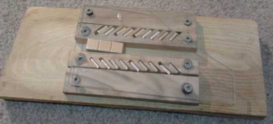
On the 8th I made and assembled some wooden pieces similar
to the images from the book, but having so few magnets, I tried spacing
them out. 1cm per 'chute' magnet seemed to work quite well. A
projectile of 4 magnets shot out the right end at good speed. But if
slowed a bit, it 'jammed' magnetically at end of the chute. If the
projectile magnet was reversed, it shot the other way.
Using a spring scale on its side, I got the following very approximate
parameters:
-For 2.25 inches, force pushed backwards, peaking at 400g at about
1.5", or when one of the .5"x.5"x.5" 'projectile' magnets was still
left of the chute magnets.
-For 1.5" while the projectile magnets were within the chute, force was
forward of about 50 to 200g.
-For 2" when the projectile reached the end of the chute and was coming
out, forward force increased, peaking at somewhere around 600g. (The
scale ends at 450.)
-For a further 2" as the projectile came out the end, force was
backwards, peaking at about 400g and decreasing the farther the
projectile was from the chute.
But what did all this prove?
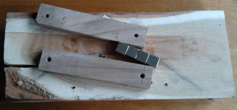 On the 10th I
tried making an arc of magnets. Extended to
a circle, this would apparently be called 'radial flux' since the
angles were radial and the intent was to have the single magnet outside
the arc. Results were unclear and I lengthened it from 9 magnets to 15
to try and be sure I wasn't getting end effects even near the middle.
Results seemed pretty ho-hum - a complete circle might work, or just
sit there.
On the 10th I
tried making an arc of magnets. Extended to
a circle, this would apparently be called 'radial flux' since the
angles were radial and the intent was to have the single magnet outside
the arc. Results were unclear and I lengthened it from 9 magnets to 15
to try and be sure I wasn't getting end effects even near the middle.
Results seemed pretty ho-hum - a complete circle might work, or just
sit there.
Then I wondered what would happen if the moving magnet
was inside the arc. Then the ends of the long magnet would be closer
to the arc magnets than the middle. That would in a loose way simulate
the Howard Johnson design without a crescent moon shaped magnet. The
wood holding the magnets was in the way, and if I placed the large
magnet on top, it would pull the arc magnets out of their slots as I
hadn't bothered with a piece of clear plastic over it this time. So I
flipped the board over to try to get on the inside from 'underneath'.
I soon found that when the moving magnet was placed along
the arc of the angled magnets, that is to say, about directly above
them, and then twisted to try and line it up, there seemed to be a
'creep' to the right. If the magnet was coaxed to the right angle -
about in-line - with a couple of pieces of wood, it definitely seemed
to always slide along the arc clockwise, anywhere in the arc except at
the right end. If it was turned around, it went the other way. Assuming
the arc was enough of a circle that the propulsive force didn't result
from some end effect, it should definitely provide motive torque. This
unexpected configuration, with the angled magnets angled 'crosswise' to
the long lone magnet instead of towards or away from it, definitely
looked promising enough to be worth making a full circle rotor and a
stator and trying it out.
So I made a 7.6" rotor of UHMW using the CNC router. It didn't work at
all. With 45 magnets in a ring, there was no more tendency for it to
move either direction. Various orientations and spacings of the long
magnet seemed to make no difference in this respect. Furthermore, if I
removed some of the magnets to make it back into an arc, there was
still no tendency for the rotor to turn in either direction. This was a
surprise, as the only evident differences now from the original setup
were that the arc was more curved, and the spacing of the angled
magnets was slightly larger.
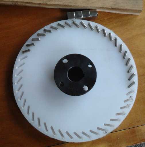
The first rotor (some magnets removed)
Surprisingly after the very promising arc tests, it had no apparent
tendency to rotate
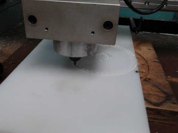
Routing the rotor
At the end of the month I tried a few more things. I found that if the
unit wasn't on a shaft, it tried to twist around with the cube magnets
at the center of the rotation.
 I decided to
look more closely at the Yildiz magnet motor, which has been widely
demonstrated. I came away from a whole bunch of diagrams, not all
compatible with each other (probably representing different
'embodiments' of the design), hoping that the salient feature was the
angled magnets on the rotor, with stationary magnets forming and inner
and outer stator. If it was, I should be able to make a similar unit
but with axial flux, where it would have an upper and lower stator
instead. That would be simpler to make. Noting the different number of
magnets on each element, I first decided to do the two stators with
different numbers as well, even tho they would be the same diameter.
Then I thought that it might work better if they were the same, but one
could be turned slightly WRT the other one, so that the magnets of one
would line up with the gaps of the other. The relative positions could
be adjusted for maximum performance... assuming the whole thing worked.
I decided to
look more closely at the Yildiz magnet motor, which has been widely
demonstrated. I came away from a whole bunch of diagrams, not all
compatible with each other (probably representing different
'embodiments' of the design), hoping that the salient feature was the
angled magnets on the rotor, with stationary magnets forming and inner
and outer stator. If it was, I should be able to make a similar unit
but with axial flux, where it would have an upper and lower stator
instead. That would be simpler to make. Noting the different number of
magnets on each element, I first decided to do the two stators with
different numbers as well, even tho they would be the same diameter.
Then I thought that it might work better if they were the same, but one
could be turned slightly WRT the other one, so that the magnets of one
would line up with the gaps of the other. The relative positions could
be adjusted for maximum performance... assuming the whole thing worked.
The 15th was taken up by buying some 1/4" plastic to carve the stators
out of. On the 16th I cut the stators on the CNC router. On the 17th I
got to the rotor.
Again it didn't work at all.
One of the stators
It had seemed strange that there should be two different
designs in the 'Free Energy Info' book for the Yildiz rotor. I had
assumed
that these were different 'embodiments' of the device from the patent.
I seem to have acquired a talent for
glossing over essential details.
It finally dawned on me that the first 'rotor' described in the book
couldn't be a rotor for the machine as described. It must actually be
the 'inner stator' and not a rotor at all. It was either described
wrongly or translated wrongly from the German language patent. It also
seemed that it was probably the key to the whole thing. It was the one
part that, while in cross section appearing to be symetrical around
360° (above image), it wasn't, as views from the side show.
Yildiz Inner Stator
The stator reminded me of the "V-Gate" design. And
it all looked rather complex to make.
I started to think January another month without anything
special to show for it. Then on the 19th I looked up magnet motors on
Youtube. There seemed to be a lot more there than the last time I
looked. One video showed some new designs which it implied were by
Yildiz.
Muammer Yildiz installing some magnets, and some
recent designs attributed to him, clipped from a youtube video.
Perendev Motor
But another design stood out to me: the Perendev design,
in particular a live demo at some hobby(?) show. (I later watched again
and realized they were starting it by hand and it gradually lost speed.
But the earliest demo by the inventor, Mike Brady, appeared to work
well.) The Perendev design
was
glossed over the the Free Energy Info book. But it seemed
simple and robust, and didn't seem to need any odd shaped magnets. The
three rotors looked just
about like my first one - that's what immediately grabbed my attention
- and the stators were of similar construction to the rotors. It looked
makable!
There was a live demo of a Perendev unit at some public event.
[http://www.youtube.com/watch?v=fqJDrFMqGlU&noredirect=1]
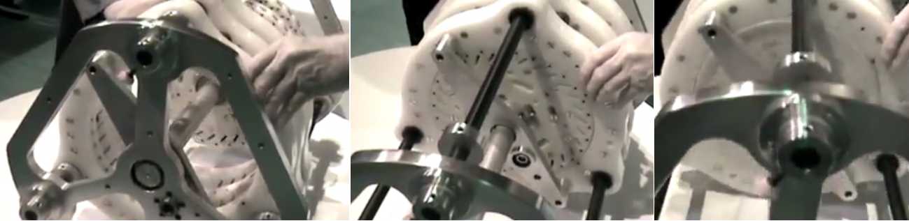
The stators slide over the rotors to start the machine turning.
And off again to stop it. Other designs used two part, hinged stators
that the top side swung out away from the rotors.
Although only a few of the magnets were installed in the rotors
(1/5th?),
it buzzed away wildly when the stators were in place.
A couple of similar Perendev motors in other videos performed similarly.
[http://www.youtube.com/watch?v=PNj6uGW-Ly0&noredirect=1]
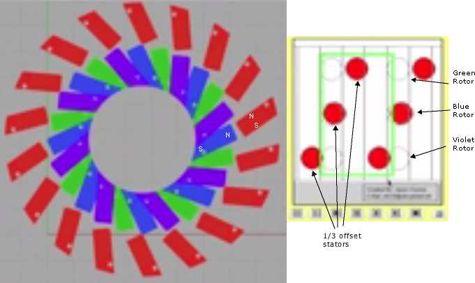
Some essential workings of the Perendev design, clipped from the video.
The three sets of rotors and stators are offset (either the rotors or
the stators could be shifted)
for a "three phase
motor" effect where there's more torque in any position.
"Not needing any odd shaped magnets" now looked like a bit
of a trick: the stator magnets were magnetized across the cylinders'
diameter instead of end to end. Would anybody make those? But I could
do it the other way around: the square magnets on my rotor were
magnetized across the thickness, and I could use the cube magnets with
the pole in and out on the outside. AFAICT it shouldn't matter which is
which.
I set up my rotor and moved a couple of cube magnets just
to the outside on opposite sides. I needed both hands to hold the two
magnets so it was hard to give the rotor a spin, and the poorly
supported rotor kept
wanting to tip over... but it did seem it turned more easily in one
direction than the other. That made it worth making a stator and
setting it all up to try it properly.
But there was something else,
about "magnetic shielding" being required to create the force imbalance
- in essence, to create non-linear magnets like Howard Johnson had
made. I was able to find out very little about this aspect, save for
seeing a sleeve somewhere, and the following piece, copied whole (my
bold, minor corrections of grammar & spelling):
Trying to understand the Perendev motor
Through the use of three wheels with properly spaced magnets , you
create the equivalent of one wheel with continuous or overlapping
magnets depending on the size and spacing of the magnets. The wheels
and outer stators have different numbers of magnets to prevent locking
of the magnets. In the cases of the small and large motors , the number
of magnets is 30 on the wheel for 36 stators, and 17 on the wheel for
18
stators. This number is significant only in that it is in perfect
timing with three wheels. I think different numbers of magnets would
work as long as there was the proper number of wheels to achieve
timing. Know you have achieved a wheel that spins freely within the
stators. At this point there is equal pushing and resistance forces
within the motor. To achieve propulsion the balance of pushing and
resistance must be offset. This is achieved with the use of magnet
shielding and angling the magnets. There are two types of magnetic
shielding, one like a sleeve around the magnet , used to focus the
magnetic field and the other , a half tapered ring placed on the
approaching sides of the magnets.The shielding is simply the path
of
least resistance and so , pulls the field down on the approaching side
in turn lowering the resistance side and offsetting the balance.I
believe the clearance between on coming magnets is an important factor
as well.
Roger Cote
[http://www.fdp.nu/perendev/rogercote.asp]
Another you-tube
experimenter said magnetic shielding was the "holy grail" of magnet
motor operation.
If the "shielding" was
"simply the path of least resistance", that meant it should be iron or
steel rather than something exotic like bismuth. (Bismuth is
diamagnetic - repels both N or S magnetic fields.)
But Mike Brady specifically said in his demo some holes
were for magnetic shielding, which hadn't arrived yet -- and yet his
motor certainly appeared to run without it.
I figured if it needed
multiple rotors, I'd have to make
new ones with fewer magnets or I'd run out of them. 14 per rotor
instead of 45 would be about right. So I might as well do a new rotor
as well as a stator. But, I could make rotor and stator pairs as single
units on the CNC router, the last cut being around the circumference to
separate them, with a 1/8" router bit yielding that size gap beween
rotor and stator. The white UHMW polyethylene I'd picked for the first
rotor seems like the ubiquitous material for them in most of the
working units.
Some magnet motors use electromagnetic coils to counter
permanent magnets at selective points and get the rotor past "sticky
spots". On the 21st I started thinking more about magnetic 'shielding',
and about the fact that a magnet moving across a conductive material
such as aluminum creates an electric field within the material. This in
turn creates a counter magnetic field that causes the drag. (I tried to
use this effect in the Magnetic Impulse Torque Converter a whiile back.
But I found the effect has limits and beyond a point doesn't increase
linearly with speed.) The introduction of this transient third magnetic
field by the moving rotor magnets could selectively counter or enhance
the magnetism of the stator magnets to produce the unbalanced magnetic
forces necessary to rotation - without coils. The most conductive
substance is silver, and the amount required should be low enough that
this costly metal won't add a lot to the price. Otherwise copper would
be the alternative.
On the other hand, this always results in a frictional
delay rather than an acceleration. Perhaps shielding is best done with
a magnetic metal instead, resulting in attraction, or a directional
decrease in repulsion between two like poles.
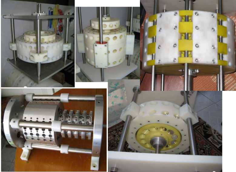
My New Design
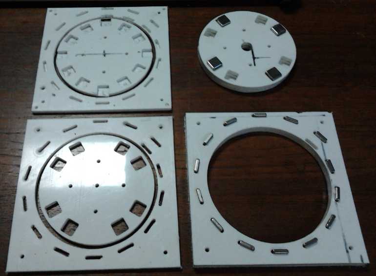
Rotor and stator pieces of my new design as first made
Looking at Yildiz's helical magnets inner stator again,
and
thinking of the V-Gate and other spiral or helical designs where the
rotor at least went around most of a circle reliably, I decided to make
rotors
with a single spiral, with 14 magnets. There might be 'lumpy' torque,
but there should be torque around the circle, with just one spot per
rotation, at the end and start of the spiral, where the motor would
tend to brake and jam once turning. If the motor had two rotors set at
a 45° angle to each other and 4 magnets on each stator, there would
be 7 stator magnets in pushing areas and just one at the jamming point
at any given time. Some strategic magnetic shielding on the rotor might
reduce the jamming force at that point as well. That *sounds* like it
should work, but this stuff is pretty tricky.
If nothing else worked, I could probably replace the first
magnet from the spiral with a coil, to come on for a moment and push
instead of braking, just as each magnet went by it. A hall sensor could
trigger the pulses. This apparently works in many designs, and the coil
uses substantially less energy than the machine generates. The Free
Energy Info book recommends this type of motor since
permanent-magnet-only motors are so tricky to get working.
Oops -- such a coil would have to be on the rotor rather
than on the stator! For the coil to be on the stator, the stator would
have to have the spiral, and the rotor would have the 4 magnets that
went by the jamming spot. That required redoing some of the work of
making up the G-Code for the rotor on the 22nd, to change the diameter
of the spiral so it ended up on the stator outside instead of the rotor
inside. The 4 cube magnets per rotor-stator pair hadn't been set up yet
anyway and needed doing either way. They would go on the rotor.
Trying things out by hand with just one of each magnet
with a slab of plastic between them on the 23rd, I found that a 1/8"
thick piece of steel on the leading edge of the "stator" magnet (.5 x
.5 x .125", N face facing rotor, inwards) indeed substantially lowered
the braking force as the "rotor" magnet (cube, N at front, S at rear)
approached the "stator" it, without having major effect on the very
strong propulsive force once it reached the critical angle. The
attraction to the closer steel somewhat canceled the repulsion from the
north magnet face, producing a sort of "magnetic force diode" effect.
It seemed square-on magnets, not any odd angles, worked best.
With a piece of steel in front of the "sticky spot" magnet
at the start of the spiral, I now had good hopes the rotors would
propel past that spot and not stop there. A shield in front of all the
stator magnets should provide the most net torque.
One might expect that the shield could as easily go on the
front of the 4 rotor magnets instead of the 14 stator magnets. The
effects during the approach and crossing seemed pretty similar, but
after the magnets passed, there was more reverse thrust (tho still
small), starting a little earlier. So the best effect will probably be
a .125 x .125 x .5" steel 'shield' piece in front of each stator
magnet. So I'll make the slots 5/8" long instead of 4/8". One caveat is
that I used a piece of steel over an inch long (~ .125 x .5 x 1.5") for
the tests.
Another effect could be had with diamagnetic material that
repels all magnetic fields. The tailing edges of the stator magnets,
for example, could have a piece of bismuth, the strongest diamagnetic
material. This would reduce or cancel the weak but lengthy reverse pull
that occurs after the magnets faces have crossed. However, the effect
is tiny compared to the reverse pull at the leading edge and bismuth is
probably expensive. If any 'shielding' makes the difference between
'doesn't work' and 'works', it'll be the steel. The bismuth is
something that might be tried to see if there's worthwhile improvement
after a working unit has already been made.
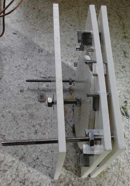
I had got some new mechanical ideas from some of the
youtube videos, even from machines that were unfinished or didn't work.
The axle would be a threaded rod with a ball bearing at each end. The
rotors would be held on with nuts and could be spaced any distance and
angle. Four more threaded rods, at the outer corners, would space and
hold the stators and ends (with bearing holders) together.
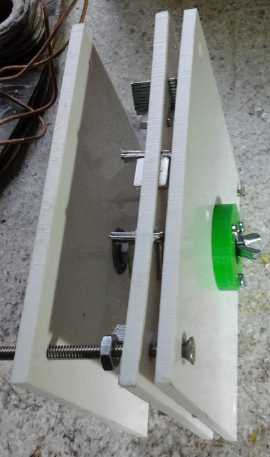
Two views of the motor with shielding
pieces but only one rotor & stator
For that iron, I'd used nail gun finishing nails, the same as I had
used in my early motor coil cores, since they had the right magnetic
characteristics of attracting magnets but not magnetizing.
On the 28th I drilled some holes in the stator and ran
them together to make slots at 90° to the magnet slots. I filled
these with more nail strips. This time, the rotor seemed to have a
preference. Spun up by hand, it seemed to run longer in one direction,
slowing more gradually, than in the other, where it seemed to 'brake' a
bit. But I didn't have everything properly assembled, and I would guess
it wouldn't be enough to overcome friction. Next I'll fit out both
rotor-stator pairs and get everything properly mounted square and not
wobbly. If that doesn't turn, I'll make more with more room on the
stators for larger iron strips, as these ones, not anticipating the
need, are too cramped.
I'm convinced it can be done, but in the end I wasn't
really sure it preferred turning one direction over the other. But if I
do get one turning itself, I'll mount a third stator
with air core coils on it, axial flux, between the two rotors as a
'power take off'. I don't suppose it'd make many watts, but even a few
is a good demo.
Electricity Storage
Turquoise Battery Project: new test
cell with 60:40 Ni:Mn oxides and double electrodes
I finally put the four electrodes I made a couple of months ago
together and
into a 'cosmetics' jar and filled it. I still wanted to verify for
certain that the 60:40 Ni:Mn oxides ratio worked and didn't degrade
like the more 'manganous' ones, and to at least double the current
capacity if not improve it more, and have a decent demo cell.
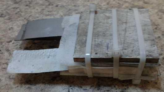
Stack of electrodes with hard plastic ends, clamped by cable ties.
Using polypropylene fabric instead of watercolor paper around
all the electrodes was a mistake: stuff leaked out of the electrodes.
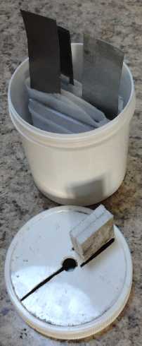
Initial install
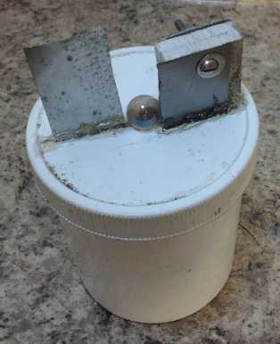
Initial appearance. This fine work soon had to be ripped open.
Results were immediately poor,
and I found a bunch of crap on the bottom and dark electrolyte. I
emptied it and refilled with fresh electrolyte. I ended up doing this 3
or 4 times, each time once a day and then leave it to charge, until I
had it working properly and charging at 1/4 of an amp.
The main problem was that I had used polypropylene cloth
to wrap the positrodes, and it was seeping nickel hydroxide. It wasn't
solid enough. I inserted two pieces of watercolor paper between the
plus and minus electrodes. The electrodes continued oozing nickel
hydroxide out the edges, but now it wasn't shorting the electrodes
together... at least not immediately. I should look at my own
instructions, which IIRC say to use the watercolor paper and then put
some PP cloth in between the papers to allow gas bubbles to escape.
It kept having self discharge problems and I stopped
trying to rinse and replace electrolyte, so I guess I'll have to pry
the layers apart and redo it with the Arches watercolor paper around
all sides of all electrodes.
Graphite Felt
Someone mentioned "graphite 3D felt", so I looked it up. I
found that there is such a thing. I'll order some if I can get it for
a reasonable price. It seems
likely that if the positive electrode powder was placed on graphite
felt and the compacting box shaken to fill the felt spaces with powder,
then compacted, one would have a far more conductive electrode than a
simple sheet of graphite with graphite powder in the electrode mix.
Compaction would have to be on the flat. Filling in stages via an edge
would be out.
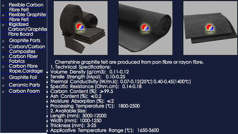 http://www.chemshine.com/EproductShow.aspx?id=2
If one can also do something similar for the negatrode -
or use the felt there as well - it
might make for much better active substance utilization and much higher
current capacities than I've been getting.
I'm guessing this would make real, practical batteries.
Pulse Charger for
Lead-Acid
Batteries - Limited Successes
I've felt for a long time that I haven't been getting the results I
should be
getting when renewing PbPb/SO4-- batteries because they need a pulse
charger to help activate the sulfates which have become crystallized
and passivated on the plates. I had several batteries waiting for this
treatment, and I wanted a couple for the electric Mazda RX7 - and any
other electric transport I have working, such as the boat and Electric
Caik outboard. But I keep putting off the project of making one in
favour of more interesting things.
On the 14th I bought another "reconditioned" battery for
the Mazda to get its range back up, then I started to consider that I
could probably use the 555 timer pulse generator circuit from the
Lambda Ray collector with components sized for a much lower frequency
as the pulse generator for the pulse charger. Then it occurred to me
that I could use the collector's MOSFET driver circuit as well, with a
lower voltage, higher current MOSFET. In fact, I had only to make
another identical circuit board and populate it with some different
values of the same components. It would supply pulses to a battery
instead of to a coil. The only other thing I would do would be to slow
down the ultra-fast switching by putting a gate resistor between the
gate driver mosfet pair and the gate.
Apparently, I created not just a lambda ray circuit but a
more general purpose pulse generator and pulsed load driver. (In the
end, I omitted the driver pair entirely and drove the output transistor
straight from the 555.)
The circuit would be powered from a 12 volt source - such
as any nearby battery. A higher voltage would be needed for the pulses
to to the battery under charge, meaning in this case my 25V, 5A
rectified transformer.
All of a sudden, making the pulse charger I wanted looked
almost trivial. The next day I dug out the 2 spare copies of the PCB
artwork, ironed them onto boards, and etched the boards using the
technique of just putting the board in the etchant and coming back
after a few hours.
On the 19th I made the charger and put it on a battery. It
seemed to work well. In a quest for finding what range of frequencies
were used for pulsing, I had e-mailed someone. He said he didn't know,
but mentioned a couple of commercial units. I set mine to about 600 Hz.
But the price for one of the units mentioned was pretty low, and I
started thinking why didn't I just buy one? Strangely, if I'd ever had
that thought before, it had been banished from my mind without looking
around first. It would have been good economy. On the 20th I went to a
couple of battery places. The second one had a pulse charging unit
claiming to solve everything and bring any lead-acid 12V battery back
from the dead for 123$ + taxes, and I bought it. It turned out it used
40-50 KHz pulses. I'd never have expected such a high frequency from
the term "pulse charging".
It must now restore say three or more otherwise "finished"
batteries to lengthy useful service to pay for itself.
I started with one that has been 'renewed' with sodium
sulfate, but which wouldn't take a charge. It would charge up to over
12 volts, then the voltage would start dropping, and once left alone,
it would drop to 10 or 8 volts. This could be repeated, but it would
still defy holding any charge gained. I have had several such
batteries, which I gave up on in frustration. With the high frequency
pulse charging most of the day, it was up to 14 volts and obviously
holding charge.
Then, with my mind churning over some e-mails and thinking
that those who made such things professionally probably would do a
better job than me, and still not knowing what frequency was 'normal',
having found no info on the web, I bought a commercial pulse charger.
It turned out to be 40-50 KHz, a rate I'd be more inclined to call
"ultrasonic charging" than "pulse charging". My 600 Hz was very low by
comparison.
But although I was at last able to charge up batteries
that defied charging with regular chargers, the units didn't seem to
increase amp-hour capacity of weak batteries as far as I could tell. I
also came to the conclusion that some of the batteries I had bought as
"spent" from the recycle pile were really not sulfated up enough to
have been renewed. They had low specific gravity, sometimes low
voltage, and didn't have much capacity because there wasn't enough
sulfate on the plates to reconstitute the acid.
http://www.TurquoiseEnergy.com
Victoria BC