Turquoise
Energy Ltd. News #73
(February 2014)
Victoria BC
by Craig Carmichael - posted March 5th, 2014
www.TurquoiseEnergy.com
= www.ElectricCaik.com
= www.ElectricHubcap.com
= www.ElectricWeel.com
Spotlight:
Graphite Foam & Graphite
Foil Yields Good NiMn Battery Performance (see Month in Brief,
Turquoise Battery Project Report)
Month In Brief
(Project Summaries)
In
Passing
(Miscellaneous
topics, editorial comments & opinionated rants)
* Economic Collapse Nearing? Ready?
Electric Transport - Electric
Hubcap Motor Systems
* Centrifugal Clutch for Planetary Gear Torque Converter?
Other "Green" Electric Equipment Projects
* LED Lighting: New 12V driver boards; Emitters performance update:
degrading - higher voltage over time
* Peltier Modules Heat Pump
* New design "pins" heatsink
* Graphite as heatsink material
Electricity Generating
* Magnet Motor - magnet twisting idea
Electricity Storage - Turquoise
(NiMn) Battery Project etc.
* Graphite felt, graphite foil
* New Electrode Flat Compactor
* New cell "OJC1" with graphite felt & foil PERFORMS - 100 mA/sq.cm
current density!
* Performance deterioration
* Zinc current collectors gradually corrode
* Graphite foil negode current collector: Doesn't bubble hydrogen and
cause self discharge!
* Tentative conclusions: this cell is workable, should last a long
time,
next cell should be
better.
No Project Reports on:
Lambda Ray Collector, Pulsejet steel
plate cutter, CNC Gardening/Farming Machine (sigh, maybe summer 2014...
2015?),
Woodstove/Thermal Electricity Generator (will probably abandon),
evacuated tube heat radiators, individual EV
battery monitor (will probably cancel... well, maybe).
Newsletters Index/Highlights: http://www.TurquoiseEnergy.com/news/index.html
Construction Manuals and information:
- Electric Hubcap Family Motors - Turquoise Motor Controllers -
Ersatz 'powder coating' home process for
protecting/painting metal
- Preliminary Ni-Mn Battery Making book
Products Catalog:
- Electric Hubcap 4.6KW BLDC Pancake Motor Kit
- Electric
Caik
3KW BLDC Pancake Motor Kit
- NiMH Handy Battery Sticks, 12v battery trays & Dry
Cells (cheapest NiMH
prices in Victoria BC)
- LED Light Fixtures
(Will accept BITCOIN digital currency)
...all at: http://www.TurquoiseEnergy.com/
(orders: e-mail craig@saers.com)
February in Brief
I determined that I wasn't going to work on just
one project in February. My first thought was to pick four and spend a
week on each one. Then again, it was already the 5th so the first week
was largely gone.
I spent that day mounting and connecting a peltier modules
heat pump that would
use water circulation and, having done most of the work previously
before being sidetracked by trying to make evacuated pipes, got as far
as a test. The water didn't circulate fast enough by convection, and
the warm side radiator didn't cool enough without a fan - or even with
one unless the air was to be ducted across the radiator fins. I thought
maybe regular heatsinks with fans - like on the fridge - might after
all be the best way to go. I ordered three heatsinks of a new design,
pure aluminum with round posts instead of fins. I tried one on the
fridge and it wasn't as good as the first one with closely spaced fins,
and they cost more. I can compensate with faster fans for testing, but
it was disappointing and rather costly.
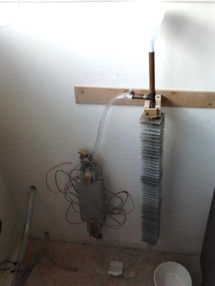 Heat Pump initial experiments
complete with filler funnel and drip tray
The next day I
started in on a centrifugal clutch for the
Chevy Sprint. The planetary gear torque converter had essentially been
working in September 2012 except for the flat belt and clutch drive
component. This time I thought would try a chain again, and the
centrifugal
clutch. It sounded simple enough, but soon I found it wasn't going to
be done without some challenges. The centrifugal clutch units available
had sprockets for the wrong size chain. I did some turning on the one I
bought so I could weld a #50 chain sprocket onto it. Then, they
were too wide to fit on the shaft
without modifying the mounting box and making a longer shaft, and I set
it aside. That's probably what stopped me the last time I thought of
this, but I had forgotten about it.
On cars, last month I saw another in-wheel motor and
mentioned the problem that the unsprung weight of motor mounted wheels
is bad
for vehicle handling, and that a better arrangement for a new car was
"wheel motors" mounted inboard and connected to the wheels by CV
shafts. The shafts would hardly affect the efficiency. Now I've found
another car design doing it that way:
[citroen-ds3-electrum.gif]
 Next I did a
constant current power supply circuit design and
board for LED lights. I liked the flat panel lights I bought last month
and thought they would be great to produce, but an updated constant
current supply was the next thing I needed to make any LED light if it
was to run on 12-15 volts rather than strictly on 12.0 volts, LED s
being
quite particular about their current and voltage. Given an output
voltage not very far below the input, a linear regulator can be as
efficient as a switching regulator - ideally even better.
Next I did a
constant current power supply circuit design and
board for LED lights. I liked the flat panel lights I bought last month
and thought they would be great to produce, but an updated constant
current supply was the next thing I needed to make any LED light if it
was to run on 12-15 volts rather than strictly on 12.0 volts, LED s
being
quite particular about their current and voltage. Given an output
voltage not very far below the input, a linear regulator can be as
efficient as a switching regulator - ideally even better.
At the same time,
when I tested it using the 3 Cree XM-L-H emitters in series I had
removed from the kitchen, I discovered that the original voltage of
about 2.9 volts per emitter had risen - had degraded - over 2-1/2
years,
and they now took a 3.5v + 4.0v + 3.5v = 11.0 volt supply to obtain 1
amp and their 'normal' brightness, instead of 2.9 + 2.9 + 2.9 = 8.7
volts. This was somewhat disconcerting. They may have been running
rather warm to hot in the kitchen ceiling, and I've switched to
different emitters in more recent lights, but the
idea of 4 such emitter in series (11.6v when new) to attain 100 lumens
per watt efficiency at 12 volts now seems unattainable over time, even
tho
they'd do it fine at first. I'd better measure the other '11-12 V'
emitter lights I've been using and see how they're fareing over time.
I have some smaller emitters suitable to spread a number
of over a larger area to make flat panel LED lights. The heat in that
design is well spread out and hence the emitters can run at their
coolest.
I also found the first magnet motor rotor I made in
January
would try to twist and turn after all... if the axle was anywhere but
in the center, which is of course exactly where it was. That gave me
something that seemed better to go on, and
then I figured out how I could use the spiral stators I'd made with new
axial flux rotors. On the 13th, after trying again to fix my 3D printer
without success (but with some progress this time), I started in with a
spreadsheet to calculate the G-Code co-ordinates to make said rotors
with the CNC router.
However, mid month I felt I had to start on the long
overdue project
of removing an old brick chimney from my house. Many of the 1100
remaining bricks
in the 22 foot stack, weighing around 3 tons, could be loosened and
removed by hand, and it
would have made mincemeat of the the whole north side of the house and
buried
anyone in the vicinity in any sizable earthquake. With all the reports
of earthquakes and volcanoes in recent times and the ever-present
threat of "the big one" on the BC coast, it seemed only prudent to
dismantle this time bomb. Unfortunately that left the machine shop and
the
electronics
lab, where the chimney ran through, in a dusty shambles until the end
of the month and beyond.
NiMn Battery Advance: Practical Cells!
The month's big news is: Better performing NiMn batteries.
Having received from "SGL Group - The Carbon Company" samples
of porous graphite felt ("Sigracell") and graphite foil ("Sigracet")
especially made for batteries (albeit for liquid electrolyte "redox
flow batteries"), I went to work on using them in a NiMn cell on the
20th.
 First I had to make an electrode compactor that compacted
on the flat, since edge compacting was out when any sort of
"dimensional" material was to be incorporated instead of just powder. I
made the box 40x40mm, requiring (according to only marginally
applicable calculations) about 10 tons of optimum pressure. The 64x64mm
electrode size would have required 26 tons - more than my press. 10
tons seemed like lots to aim for, and allowed headroom for trying 15 or
more to
see if that worked any better. I used a piece of steel big enough to
hold two electrode boxes in case I wanted to speed "production" up
later.
First I had to make an electrode compactor that compacted
on the flat, since edge compacting was out when any sort of
"dimensional" material was to be incorporated instead of just powder. I
made the box 40x40mm, requiring (according to only marginally
applicable calculations) about 10 tons of optimum pressure. The 64x64mm
electrode size would have required 26 tons - more than my press. 10
tons seemed like lots to aim for, and allowed headroom for trying 15 or
more to
see if that worked any better. I used a piece of steel big enough to
hold two electrode boxes in case I wanted to speed "production" up
later.
For the posode I infused mixed
Monel:Ni(OH)2:KMnO4:graphite:Sm2O3
powder into 3 layers of graphite felt by vibration and tapping in a
plastic jar. I wetted the surfaces and put
them in the box. The felts, initially over half an inch tall, squashed
down to an electrode about 2+ mm thick. The felt added about 15% to the
electrode weight, but since it also made the cell work better than
any previous cell, this was well worth it.
The negode was the same as previous ones, in fact using
some left over powder mix. The 2.6mm or so thick
electrode would have had somewhere between 5 and 10 amp hours - perhaps
5 to 10 times as much as the plus side, and it took such a long time to
charge up I thought for some hours the manganese wasn't holding a
charge
at all.
This small cell sourced at least as much current as the
previous larger ones, providing up to 100 mA/sq.cm of electrode
interface area instead of maybe 20-30. That's well up into acceptable
commercial range. There was then a performance drop, but I think it was
associated with electrode expansion (and hence loss of conductivity)
from taking everything apart 2 or 3 times and replacing the negative's
current collector. I have plans for improving construction of the next
one, and now I know that graphite current collectors work fine in
both electrodes, so I won't be unclamping the electrode stack to try
zinc
again, so I'm expecting good performance without deterioration. And in
the first days of March, further load tests showed improving
performance of OJC1 with charging and cycling, which will hopefully
continue.
NiMn Ointment Jar test Cell "OJC1"
 Another
improvement of the new cell was the 'graphite
foil'
current collectors. They contain a polymer (making them actually some
sort of highly conductive composite material) and seem impervious to
anything in the battery, and while still brittle, the terminal tabs
don't break off with the slightest provocation and are still attached.
Regardless I coated
them with osmium doped acetaldehyde
to protect them from oxidation and improve conductivity.
Another
improvement of the new cell was the 'graphite
foil'
current collectors. They contain a polymer (making them actually some
sort of highly conductive composite material) and seem impervious to
anything in the battery, and while still brittle, the terminal tabs
don't break off with the slightest provocation and are still attached.
Regardless I coated
them with osmium doped acetaldehyde
to protect them from oxidation and improve conductivity.
In addition, I found that they didn't cause hydrogen
bubbling and consequent self-discharge of the negode. This let me use
them in both electrodes and ditch
the zinc current collectors, which seem to corrode away to nothing
where they're not near manganese, especially near the top of
the liquid, so they usually end up leaving
the negative terminal post detached from the rest of the electrode.
(I'm still not sure why this should happen, but it does. Maybe they
form ZnH2 rather than an oxide?)
Next I'll make a new cell and add graphite felt to the negode as well
as to the posode, and see how much that helps. These new graphite
materials are changing the picture, and in whatever time I find
to pursue the project, I don't expect to stop now at least until the
small "ointment jar" Ni-Mn test cells are driving respectable loads in
the 2.4 - 2.2 volt range and holding respectable energy and amp-hours.
In Passing
(Miscellaneous topics, editorial comments & opinionated rants)
Economic Collapse Nearing?
If one is watching, one senses the deteriorating world
situation in many areas and on many levels. It seems to me food prices
are rising more rapidly month over month, while the majority everywhere
is in debt or is having increasing trouble making ends meet. Sales at
most other stores (even Wallmart) are increasingly dismal, production
sits unsold and inventories build up, and shipping volumes continue
dropping. How much longer can this go on? a month? (probably) a year?
(hmm...) two years? (I doubt it.)
World
population is the highest ever and the crop year of 2012 was disastrous
virtually worldwide. I didn't notice the topic in the news in 2013
except for someone's account of seeing dirt instead of corn as he flew
over the US midwest in July, California droughts leading to crop
failures in that major food exporting state, and citrus trees getting
snowed on in the south. The last couple of winters have been bitterly
cold in much of North America and harsh in various ways in various
other places. The world's food supply must be getting rather thinly
stretched.
Protests, riots and insurrections are occurring
in more and more cities and countries as conditions worsen. 100 million
Americans aren't working - 1/3 of the population. Europe is surely no
better. And yet, the majority
don't seem aware that anything is badly enough out of kilter to worry
about it unless disorder strikes their own area.
Do you have some bags of rice and other non-perishable
food and garden seeds - the various things that you'll need -
stashed away for a lengthy hiatus in the distribution system? And fuel
to get where you need to go? Supply shortages might last 2 or 3 or 4
years rather than weeks or months, and will start with grocery stores
being emptied in a very few hours. Famines and epidemics are likely.
And the world "pyramid scheme" financial system is
teetering on the brink of the abyss. Do you have assets under your
personal control that won't vanish if all the so-called "zombie banks*"
suddenly
close one fine day (your safety deposit box will then become
inaccessible), impose low daily withdrawal limits, or if they do the
everywhere threatened "bail-ins" - stealing money from everyones'
accounts attempting to stave off collapse? Dr. Paul Craig Roberts,
father of "Reaganomics" in the 1980 s says that if you find your
dollars becoming worthless (even if accessible) and you go to buy gold,
there won't be any. Gold, silver coins and bitcoins (or other digital
currency?) are "monetary" assets to
trade with to acquire now.
As more than one person has said, being ready years too
early is better than a day too late. An advantage of starting to get
ready early is people start to remember gradually all the items they
haven't initially thought of. Toilet paper? Salt? Coffee? Have you ever
grown a vegetable garden? - you need a whole spring and summer to
practice. I doubtless started early a couple of years ago, but I
suspect it's no longer early.
And there are nations whose "leaders", rather than lifting
a finger to mitigate the situation or even to warn the public, are bent
on starting a war - any war - to distract attention from these problems
and cast the blame on the war, when they have made things so much worse
themselves. How many people will die violently or as an indirect result
of violence, eg, starve in refugee camps, for nothing? How can we stand
up to those whose duty is supposed to be to us and insist squarely "NO
MORE WARS!" before the whole environment is brutalized for thousands of
years or even destroyed by nuclear weapons?
The seeds of CHANGE have been scattered and the spores are
blowing in the wind, but they must be nurtured, fostered, directed, by
living
people in the years and decades to come to direct the change towards
building the utopia that this planet should be and will become -
sooner, or later, according to what people do during this fermenting
and formative time.
* "Zombie banks" or insolvent
banks includes pretty much all of them worldwide - including Canadian,
which were quietly bailed out with 114 billion $ of taxpayer money in
2009-2010! China too is in serious financial trouble.
Electric
Hubcap Motor Systems - Electric Transport
Planetary Gear Torque Converter (what, again?)
After reviewing a 2012 video again, I realized that the
planetary gear torque converter had performed okay... once the car was
moving. Once moving, the car could be kept moving, with a kilowatt or
so
of power. The part I had failed to get working was a clutch to engage
the system without stalling it. How could something so common as a
clutch have prevented success and left me trying another torque
converter system? Perhaps it was because I was trying to fit too much
into the box, a pre-made space that wasn't quite big enough.
I determined to would try again, and consider expanding
the 'transmission' box to give the clutch portion space away from the
converter gears portion if that seemed to be what was needed. But it
might not even be needed. This time I would try a regular V-belt
instead of the flat belt. The flat belt was theoretically better, but
standard belts and pulleys simply weren't available as they were for
V-belts - it had been just too many experimental, homemade things in
one go.
Then I thought of the other options: a flywheel on the
motor so it could start the car moving as the motor slowed... or the
centrifugal clutch idea again. The flywheel would need a longer motor
shaft with the flywheel on the other side of the motor, since there was
no room for one inside the box.
What had stopped me from trying the centrifugal clutch the
last time? Princess Auto had them. It turned out it was several things.
I had purchased one for #35 chain. On the 6th I tried to exchange it,
but there weren't any for #50 chain, only for lighter chains. Switching
the car to a lighter chain was probably unwise. The clerk thought the
clutch might be too light for a car whatever chain it had. I bought a
#50 "weld on" 15 tooth gear whose fairly large hollow center was
intended to be welded to a standard O.D. center piece having the
desired axle hole size. On the machine lathe I turned the center hole a
little larger so it fit onto the outer clutch piece right next to the
existing gear. Then I turned the teeth off the original gear since they
would hit the chain. The new gear would have to be welded on.
The next problem was that the clutch itself was a little
too wide to fit in. I would have to lengthen the shaft and move the
motor and the torque converter planetary gears over. Or I could
reposition the bearing assembly and turn the clutch around so it stuck
out the other way. That would still need a longer shaft, but it would
be easier to move the bearing assembly than the whole torque converter
and motor.
Finally, the clutches were designed to engage when the
motor hit about 2200 RPM. That wasn't going to happen with a 0-2000 RPM
motor driving the system and a torque converter gear reduction after
that. The retention springs would have to be removed and replaced with
much lighter ones to allow it to engage at maybe 50-150 RPM instead.
Herein lies my hope that the clutch isn't too light: there'll be much
less heat generated as it engages than at the higher speed.
(Is all this really easier than getting the flat belt
clutch system to work?)
When I looked over the unit carefully to figure out the
easiest way to do it, there didn't seem to be any simple way. I think
that must be what stopped me last time. Thus it
went by default into the "too hard" bin for now as the Sprint sits out
in the yard over its third winter.
Other Green Electricity Projects
LED Lighting: New 12V Nominal Driver
Boards; Emitter Performance Update
I have been wanting some new LED lights for some time, if
only for my own use. I'm short of them
after giving 3 or 4 of the LED lamps I'd made to relatives for
Christmas in 2012. Last month I bought two flat panel LED lights:
30x60cm, 30 watts, and 30x30cm, 17 watts, from Jim Harrington who had
purchased them from two different Chinese companies. The larger 30 watt
light (70$, at Jim's cost) is amazing - it's considerably brighter than
any of my
previous kitchen lights, including dual 4', 40W fluorescent tubes.
The
smaller unit (50$) seems much less than 1/2 as bright and was
disappointing after the first one. It was said to be 17 watts, but I
measured 13, explaining part of it, and it was "warm white" which
doesn't usually perform quite as well as fuller spectrum.
However where the large
one was 40V, the smaller was 12V and hence useful with the 12V solar PV
system as well as automotive, marine and RV systems in general.
From these I got the idea of trying my hand at making flat
panel LED lights myself. I purchased some smaller 2.9V, 300mA, 120
lumen(?) LED emitters to mount spread out for making more diffused
lights 3 or 4 months ago.
At
the same time, I didn't want to make more 12.0 V
lights with just a resistor for current control, which either would
draw
excess current and blow their fuse if fed, eg, 13 volts from a NiMH
battery or up to 14 volts from a running car or solar PV system,
or else would be rather dim at 12 volts.
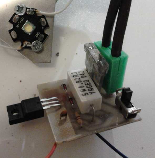
The board, showing the CAT
standard plug pins.
CAT Socket - inset.
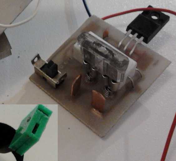 The current
control circuit was essentially similar
to my last one except I gave it a CAT plug instead of a crappy power
adapter socket, and put an on-off switch and an optional dimmer
potentiometer on the board. On the 14th I designed the circuit and
board, etched, populated (soldered the parts on) and tested it. I
didn't have the exact value of 5 watt resistor I wanted (.68Ω) for 1
amp, so I used a .82Ω and got .8 amps. (Actually, a 2 watt resistor
should be plenty big enough and I bought some .68Ω, 2W later.) I picked
a switch profile almost
at random for the parts library, and after I had made the boards, I
found a box of switches I've had almost since high school that fit
right
in!
The current
control circuit was essentially similar
to my last one except I gave it a CAT plug instead of a crappy power
adapter socket, and put an on-off switch and an optional dimmer
potentiometer on the board. On the 14th I designed the circuit and
board, etched, populated (soldered the parts on) and tested it. I
didn't have the exact value of 5 watt resistor I wanted (.68Ω) for 1
amp, so I used a .82Ω and got .8 amps. (Actually, a 2 watt resistor
should be plenty big enough and I bought some .68Ω, 2W later.) I picked
a switch profile almost
at random for the parts library, and after I had made the boards, I
found a box of switches I've had almost since high school that fit
right
in!
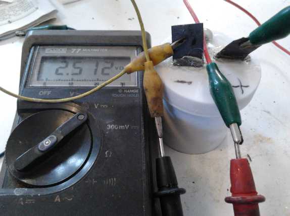
It seemed to work well with three Cree XM-L-H emitters in
series, a convenient assembly left over from the kitchen light:
9.0 V - .1 A
11.0 V - .5 A
12.0 V - .8 A
13.5 V - .8 A
15.0 V - .9 A
16.0 V - 1.0 A
Another view with CAT
socket 'extension cord' plugged in.
The transistor needs a heatsink,
the switch needs to be taller,
and a dimmer potentiometer isn't installed (the 3 holes).
But other than that...
This was more
or less the desired range, where
if the
voltage gets low the current drops to spare the power source, ie, the
battery, but if it's higher than necessary, the current is (nearly)
constant and excess voltage is dissipated in the power transistor. I
used a rather thin cable and the voltage had to be measured right at
the board, as the cable lost 1/2 a volt at rated current. Voltage drop
is of course the objection to using low voltage - but 12V is
generally a convenient voltage for LED s.
People comment on my use of "low efficiency" linear
regulators instead of "high efficiency" switching regulators. The
efficiency of the linear circuit depends on the voltage
supplied to the LED emitters and the power supply voltage. If the LED s
need 11.0 volts and the power is 12.0, it's 92%. That's better than
most switching regulators, which are typically 80-90%. If the power is
13V, it's 85% - still as
good as most and there's no electrical switching noise. Feeding 9V LED
s
from 14 volts, however, it's down to 64% and the transistor definitely
needs a heatsink. Most ideally for four 2.9 volt LED emitters in series
(needing 11.6 volts to get an amp), the supply has to be about 12.4V to
get
full brightness, at which levels 94% efficiency is attained.
Cree XM-LAWT or XM-L-H LED emitters appeared from
the specs to be "top of the line", providing over 100 lumens per watt.
But I had been thinking lately that the three Cree emitter assembly in
the kitchen didn't seem as bright any more as it was when I installed
it in
summer 2011. Per specs, they're about 2.9 volts per emitter when
drawing one amp. Now, two of them redd 3.5 volts and the other was 4
volts, total about 11 volts. Instead of 4 emitters in series for 12
volts and 1 amp, I could only have 3. (And that was at .8 amps instead
of 1.)
Whether they deteriorate(?) like this normally, or if
perhaps the cooling was insufficient and they were running too hot -
likely they were pretty warm - I'm not sure. But it may be just as well
I never sold
any of the 12.0 volt, Cree emitter globe lights, and that I went with
other emitters for later
lights.
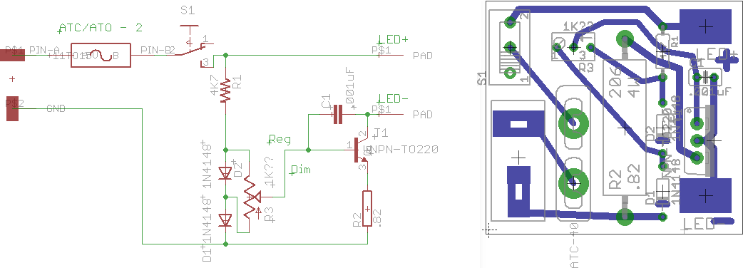 The LED driver circuit and board - single
sided, no jumpers. (EAGLE files on request)
The LED driver circuit and board - single
sided, no jumpers. (EAGLE files on request)
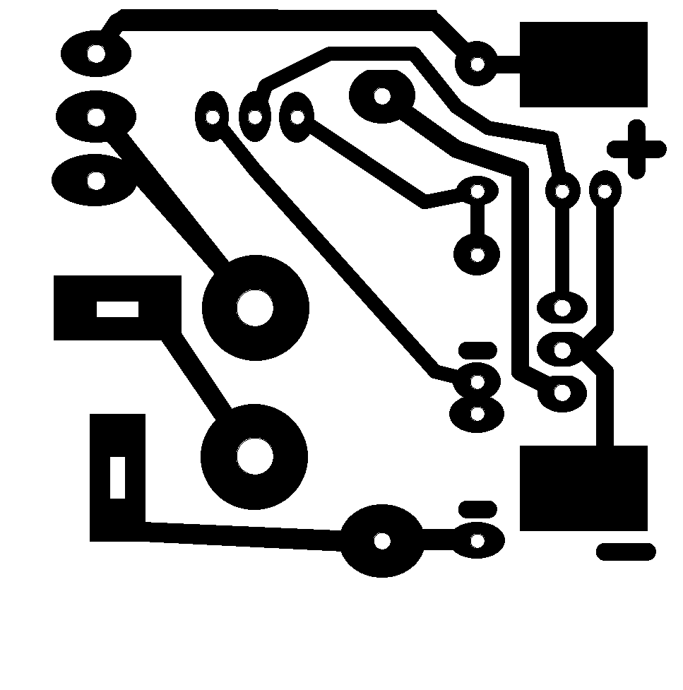 The board (correct size at 600 DPI).
I upped the pad sizes (better for single sided boards) in a paint
program.
This was printed on a laser printer on glossy magazine paper
(12 copies on a page) and transferred to the PC board with a hot iron.
With 12v 'constant current' boards ready to go, I'm now
ready to make LED lights - flat panel, globe, or any sort of portable
lamp. The control could also be placed in a separate box and be a
separate product, wired to the light with a two wire cord. This would
also allow placing
them where convenient for the user while the light is in an awkward
place to reach like
on the ceiling.
Peltier Modules
Heat Pump
I
still had the water circulation peltier heat pump unit
I made but didn't connect and install last spring. I got diverted
by the evacuated pipe radiator
idea at that time. At long last I made a mounting and hung it on
the wall on
the 5th,
connected the warm
side loop, and tried it out. At 20 volts and 4 amps - 80 watts or 10
watts per peltier - the warm side got overly warm after 20 minutes or
so. The flow probably wasn't very high: the bottom wasn't as warm as
the top. But it was too warm overall everywhere. A pump might be better
than convection flow, but a fan
across the radiator fins would probably make more improvement overall.
The cold side with no radiator loop must have picked up a lot of heat
from the warm side, because it didn't feel very cold.
The next morning I hung a 48 volt
'computer' fan on the side, and turned the supply to 23 volts, the
lowest at
which the fan would run, and gave it some time to reach a steady state.
It drew about 5 amps, so 115 watts, or 15 per peltier. (The hottest
thing in the room was the lab power supply driving all this.) I dumped
a bit of powder into the filler pipe, from which the flow rate of the
water could be more or less seen - maybe an inch a second. It wasn't
fast enough, because the water, cooled by the fan and the radiator,
came in at the bottom at 31° (centigrade) and exited the top at 42.
That needs to be brought down to a 3 or 4° difference. A circ pump
would obviously be required to attain that with this setup. Another one
on the cold side is probably implied. The units from TEC-TEG were
obviously intended for pumped applications, having dual inlet and
outlet pipes of just 1/4" I.D., and considerable internal convolutions
increasing flow resistance. Nor was the one fan sufficient as set up,
since it would have been better to cool the water to 25° or less,
the room being 20° by the same temperature sensor. With a proper
casing around the the radiator to steer air flow across all the fins,
one fan would probably be sufficient.
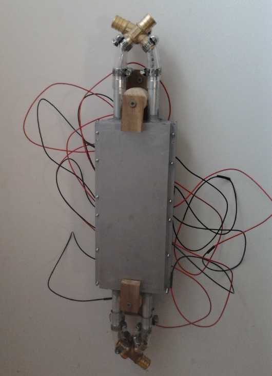 Closeup of the main unit with 8 peltier modules.
Warm side is 'in', cold side against the wall.
My thoughts last year were that a 6° outside design
temperature versus 20° inside is only 14° difference, so one
might aim to keep the total difference across the peltier modules
within about 20° and get up towards 2 to 1 coefficient of
performance
(COP). But more carefully taking everything into account, it'll be
deceptively tricky to keep the differential even under 30°, which
might also be
considered the maximum workable range for any sort of non-trivial COP,
around perhaps 1.5.
One might at best - and at least - attempt to stay within the
following ranges:
6° - outdoor air temperature (OAT)
5° - cold water return (BTW, that'll be water with ammonia to
prevent freezing)
3° - cold water out from heatsink, entering cold outdoor radiator
2° - cold side heatsink
0° - cold side of peltiers
---
20° - indoor air temperature (IAT)
23° - warm water return
27° - warm water out from heatsink, entering warm side radiator
28° - warm side heatsink
30° - warm side of peltiers
So the objective can only be to get some worthwhile
gain, to create units that put say 1.5 times as much heat per watt into
the
heated space as an electric resistive heater, and then wait for
better peltier modules to come on the market and improve that figure to
at least 2, or maybe 2.5, 3 or 4 times. Then one is ahead of the market
with optimum components, tested unit designs, and control software
already
written - ready to start production when others are just thinking about
the possibilities and
starting to design theirs.
I figured that the alternative to pumps of course would be
the elusive
evacuated tube radiators. I'm not sure they'd replace the fans - inside
and outside - with so much heat to be dispersed into the air at such a
low temperature differential. But these fans would be small and
relatively quiet
'computer' type fans, not the compressor based heat pumps or Telus
equipment boxes with loud fans that are an affront to household quiet
and
to neighborhood peace.
On the cold side with liquid circulation, having a water
pump might be unnecessary if
larger piping is used. Using the flattened 1.5" pipe, oriented
vertically, to mount the peltiers, one could drill holes in the back
near top and bottom for 3/4" or even larger pipes, to go straight
through the house wall for outdoor radiator connections. If circulation
through a 1/2" pipe finned radiator was insufficient, it could be
increased to 3/4" pipe.
If fans are necessary, perhaps
it would be better to eliminate the indoor piping entirely and have the
fan blowing across a heatsink directly connected to the peltier warm
side plate - about like the fridge except using a substantially bigger
heatsink. Seems to me I've been here before... and after making one
I found out that most "aluminum" isn't really aluminum but various
alloys
that don't conduct heat anywhere near as well as the pure metal.
Copper, better than even pure aluminum and usually sold pure, is
getting to be very expensive. (Ultimate is of course silver, 10% better
than copper... but the price!)
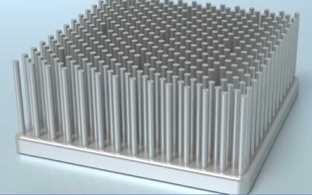 I searched on
"pure aluminum heatsink". The best looking
ones I found were ones with dense 'pins' or 'rods' at:
I searched on
"pure aluminum heatsink". The best looking
ones I found were ones with dense 'pins' or 'rods' at:
http://www.coolinnovations.com/products/heatsinks/datasheets/power-devices
These were rated as low as .06°/watt of temperature
rise with 600 LFM of airflow, for units of sizes that would hold 9
or 10 peltier modules. But with a noisy fan and for just 100 watts of
heat, that would be 6°C. Add 2° between the peltier surface and
the heatsink. One could also use more, smaller heatsinks.
I figured any of these lovely heatsinks were going to be
more than a
little pricey. It was starting to look like the cost of heat radiators
might make the whole project uneconomical. On the other hand, paying
for
more electricity every month in the winter is getting costly too.
I started to realize just how close a parallel to the heat
pump the peltier fridge really is. It uses 45-50 watts of
electricity with 'one and a half' peltiers (the 'main' 15 volt one plus
a smaller 8 volt, both rated 8.5 amps), has same same 30° spread
between warm and cold, and (according to the manufacturer's graphs) is
probably pumping around 25-30 watts of heat. Rounding that to 50 and 30
would mean it's putting 80 watts of heat into the room. (and 30
watts of cold into the fridge.) Of course, that's with '1.5' peltier
modules. The 15 volt peltier (running on about 9 volts) would account
for about 33 watts electricity and 53 watts of heat.
These are almost exactly the figures I've planned for the
heat pump per peltier unit. It just needs more units. I could probably
put 2 peltiers (better placed) under each heatsink instead of '1.5' and
still get similar results.
So a modest - or perhaps "minimal" - test unit could be 6
peltiers with 3 heatsinks using 200 watts and making 330. The cold
sides would mount on the 15 inch long flattened 1.5 inch copper pipe,
all mounted vertical against an outside wall with the large copper
pipes sticking straight out the back to the outdoors. The outdoor
radiator would still be liquid with fins (ammonia-water so it won't
freeze), hopefully with convection circulation (fat pipes) but
otherwise with some small circ pump.
I thought perhaps I'd just get 3 more of the same TEC-TEG
50 $Cdn ones as I used in the fridge, just for simplicity, rather than
importing. They seem more effective than most with a 5" computer fan
screwed on top - and I'm not even using it to best effect.
Then I
checked at CoolInnovations.com -- it's Canadian! E-mail and
a phone call disclosed that unless people would put up with a lot of
fan
noise, the medium density dissipated heat as well as the high density
at lower airflows. The 5x10" size was simply two 5x5" units bonded
together,
so the 5x5" was the best size for use with a 'computer' fan of similar
dimension. (I'm starting to suspect that these heatsinks are made of
aluminum cast in a mold. Most are extruded. Once I have the pattern, I
*could* probably cast my own... but it's probably not worth doing.)
I ordered 3 heatsinks for 50$ each, and was told that in
quantity they'd get down to around 25$. The last e-mail from them
included some cooling test specs the two 5x5" heatsinks with different
fans. I include a few useful results.
| Heatsink |
Fan |
Power (Heat, watts) |
Fan Rated CFM |
Blowing - Sucking - Best
(°c/watt) [best result format] |
| 3-505017R |
DELTA PFR1212DHE |
200 |
254 |
.064 -.053 - .053 [suck] |
|
SUNON MEC0251V3 |
200 |
75 |
.122 - .130 - .120 [.188" gap, blow] |
| 3-505025M |
DELTA PFR1212DHE |
200 |
254 |
.069 - .063 - .063 [1" blocked, suck] |
|
SUNON MEC0251V1 |
200 |
108 |
.104 - .100 - .089 [1" blocked, suck] |
On looking these over, it becomes apparent that even for
just 100 watts per heatsink, temperature rises approaching 10° are
pretty much inevitable except with considerable fan noise. Oh well, at
least the air coming off the heater should feel slightly warm and not
cool!
Heatsink Test
After the new heatsinks arrived, I tried one out on the
fridge. (Feb.21st) It was disappointing, as the temperature rise was a
little higher than with the original one with closely spaced
rippley cooling fins from TEC-TEG (www.tecteg.com), perhaps 1.5 degrees
or so. I
suspected - and still suspect -
the biggest reason was because the base was thinner, 3/8" instead of
1/2". Since the peltier modules have to be mounted over to one side,
the heat has to
spread across the base to make use of the radiating elements at the
other side, and the thicker base is better. But another factor was that
when I calculated out the total
surface area for heat radiation, it had only somewhat over half that of
the TEC-TEG unit with its closely spaced fins. And the TEC-TEG unit
works well with minimal air flow.
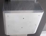 The conclusion
from all this is that I have more respect
for the TEC-TEG heatsink (left) than I had, and that I see little
chance of
improving on them very much, except maybe a bit by using pure aluminum
instead of alloy. Visiting the site again, I see the claim "Extruded
multi-fin heat sinks with the largest Thermal Conductivity ratings in
the market today."
The conclusion
from all this is that I have more respect
for the TEC-TEG heatsink (left) than I had, and that I see little
chance of
improving on them very much, except maybe a bit by using pure aluminum
instead of alloy. Visiting the site again, I see the claim "Extruded
multi-fin heat sinks with the largest Thermal Conductivity ratings in
the market today."
Possibilities include buying more of them, casting
my own similar units (using it as a template for the mold)... and maybe
seeing
if CoolInnovations can come up with something better.
Graphite Gasket
as a Heatsink?
Perhaps the way to go would be to find something cheap
and really spread out the peltiers. Make it big. What's cheap and
conducts heat well? Perhaps graphite
gasket had a role in here somewhere. It seemed to conduct heat well -
especially along the grain, it was said. I had been going across the
grain to use it as a gasket, and yet it worked quite well. And it's
cheap.
That suggested a plan: Cut pieces of graphite gasket, maybe a
dozen, to stack over the peltier(s) warm side and stick out as heatsink
fins. Cut a piece of stiff metal - cheap steel? - to 42mm wide and
whatever length, to clamp the graphite against the peltiers. As the
graphite is compressed, it'll conduct heat better across the grain, and
the 'surplus' graphite will fan out to form heat dissipation fins. If
it worked
well enough, it could replace costly heatsinks of copper or aluminum
and eliminate the main use of an evacuated tube.
I tried it out on the peltier refrigerator. I cut 10
pieces 4" x 5.25". There was only room to have fins sticking out one
direction instead of both sides, about 3.5" long. The 10 layers didn't
automatically spread into a fan shape when one area was pressed
together and needed a wire threaded
threaded between each piece to spread them out. The temperature drops
seemed a little higher than with aluminum, but not bad. Plus, having no
effective fan and horizontal orientation, the whole thing got very
warm, so evaluation or comparison was suspect. With the fan placed on a
stool and wafting some air across the vanes, typical temperatures (warm
side) read: peltiers 44°; where the vanes come out from them (mid
stack) 41°; middle of the vanes 32°; outside end at the top
25°. This was in a nasty (for Victoria BC) cold snap and the air
temperature was just 13°, so the 25° doesn't represent almost
complete cooling. (I was working with my coat on, in the
house.)
My general impression was that it would probably work well
enough if it was carefully made, placed inside an enclosure with
"cheese cutter" wires carefully strung to gently spread the vanes
without breaking the fragile graphite, forming (with the enclosure) air
channels with good flow from a fan. One thing: I can't see using it in
a car or other moving object subject to vibration. The graphite
would probably fall apart eventually. Even cleaning the dust out
occasionally without destroying it may be a challenge. (On the 12th I
got some "graphite foil" in connection with battery experiments. It's
considerably stiffer and might be used like flat sheets of aluminum.)
A composite design might have a fat bar of aluminum (or
copper) backing the peltiers, and graphite fins clamped at a right
angle under metal along the sides of the bar. This would provide 2 sets
of fins instead of 1.
(Another use of graphite might be for lining that loosely
fitting hole in the aluminum
block
for
connecting to the evacuated pipe - one expects it'd work much better.
Now... do we still want an evacuated pipe for anything? Steam still
carries heat fastest.)
Electricity (Energy) Production
Magnet
Motor
About the first of February I discovered that the first
magnet rotor I made in January, which didn't turn at all after the
promising
experiments with a wooden arc of magnets, would try to twist around,
centered on the magnetic action, if it wasn't mounted on an axle. In
fact, it became apparent there would be a motive force with a center
placed any distance but at the
axle radius, which is of course exactly where it was. I verified this
by drilling a hole half way between the magnets and the center, and
putting a bolt through it there for an "axle". With a "stator magnet"
on the
short side, the rotor would turn one way, and with it on the long side
and the same magnetic direction, it would turn the other way. If the
stator magnet was reversed, so was the direction. There were two points
part way between on each side where the rotor wouldn't turn either
way.
A basic principle can start to be glimpsed. If magnets in
an arc shaped path are magnetically connected to a magnetic field that
wants to twist their orientation, and are prevented from twisting on
their own center by physical connection to an axle, there will be a
motive force in the direction that will move the arc of magnets towards
a less twisted position - if such a direction exists. Motive force by
magnets wanting to twist is somewhat different in concept than when
they want to move toward or away from each other by attraction or
repulsion, although these same forces are of course still the ones at
work. Of course, it has to be done with axial flux
How could the magnets be positioned on the rotor so they
made a smaller arc everywhere than the axle distance? Or a larger one?
Or did it only have to be an apparent difference, based on the
angles of the magnets as well as actual distances?
Again a spiral magnet path might work.
With the spiral, the center of the arc is always offset from the
turning
center. But only by a little bit for a gradual spiral. So this time, it
seemed that a double or triple spiral,
something like the Yildiz stator but on a flat platter, might be the
ticket. And it couldn't be where I had made the spiral of the last
attempt, on a stator outside the turning rotor. It had to be on the
rotor or on a stator parallel to the rotor with axial flux. But the new
idea, once again, seemed promising enough to try building.
Other patterns also might work. One would be a series
of arcs of smaller circles than the actual rotor diameter, with spaces
between them. Another might be a series of straight lines - an
"infinite
radius" vis a vis the actual circle. Or maybe a bunch of short spirals
like a pinwheel.
How would I test all these out? Instead of making a new
rotor for each, I decided to drill 1/2" holes through existing rotors
on the drill press, and not to make complete rotors until I found
the most promising patterns. The .5x.5x.125" magnets could be jammed
into the holes with any orientation. But the results were inconclusive
and the magnets kept jumping out of the holes.
So it looked like I'll have to make another proper set of
rotor/stator parts to get a good test. I really must get my 3D printer
working again. It would be much easier to make rotors that way! If they
spin up and the plastic won't take the forces, that'll prove it's worth
doing solid plastic parts on the CNC router.
I didn't get to it, then on the 12th I figured that I
could make larger rotors about 6.6" diameter (& 2.648" magnet
center radius) that would interface with
the spiral magnets on the existing stators from an axial direction,
without hitting the support rods in the corners. If that didn't work
(or even if it did), I
could try stators with other patterns, but the single spiral seemed
like a
good start.
Unfortunately, I had to take down an old brick chimney for
earthquake safety and my machine shop and electronics lab above it
became dust encrusted disaster areas for a couple of weeks. I turned to
another project... the battery lab was unaffected and I had new
materials to attempt to make improved cells.
Electricity Storage
Turquoise Battery Project
Graphite Felt, Graphite Foil
 I had thought
probably to set this project aside now that
I
had created a great working chemistry, and hope others would work on
production aspects, since I hadn't made a lot of headway at improving
performance to get really practical cells.
I had thought
probably to set this project aside now that
I
had created a great working chemistry, and hope others would work on
production aspects, since I hadn't made a lot of headway at improving
performance to get really practical cells.
But people e-mail me with battery making questions and
ideas, and
someone mentioned "graphite felt". I hadn't heard of
that before, notwithstanding having gone to various graphite selling
websites and looked around. And I had looked for "graphite foil"
before, but the closest thing I came up with was expanded graphite
gasket
material. I don't understand how, for all the web searches and
explorations I've done, I haven't been finding - or even finding out
about - the more appropriate materials, but there seem to be an amazing
number of forms and types of graphite and carbon materials, and just
because any given supplier has a few of them doesn't mean their web
site will disclose the existence or names of other types. You would
think there must be a comprehensive overview of conductive carbon
materials somewhere, but I haven't seen it yet. (Hmm, a search on
"conductive carbon materials" is giving some interesting results.)
I looked into graphite felt. It sounded very promising for
increasing electrode conductivity. I
e-mailed
4
companies
and
only
one
responded,
"SGL
Group
- The Carbon Company". I seemed to
be having trouble
getting a price out of them to place an order, but a goodly sample box
of their "SIGRACELL"
graphite felt and "SIGRACET TF6" graphite electrode plate material
magically arrived via FedEx one day. The plate is .6mm thick and said
to be made from expanded graphite, but also to contains a "fluor
polymer". From the specs it appears to be almost impermeable, which is
much better than regular expanded graphite.
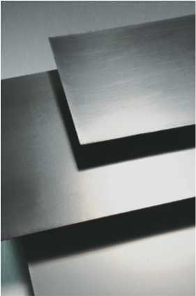
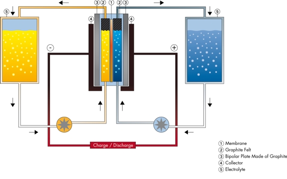 These
materials were specifically intended
for "redox flow" batteries (left). The intent was that the liquid
electrode
substance would flow through the felt, making very good electrical
contact via a zillion points in a 3D space. The felt was then backed by
the foil, which would transfer electrons from the felt to the external
terminal.
These
materials were specifically intended
for "redox flow" batteries (left). The intent was that the liquid
electrode
substance would flow through the felt, making very good electrical
contact via a zillion points in a 3D space. The felt was then backed by
the foil, which would transfer electrons from the felt to the external
terminal.
In order to use them for solid electrolyte batteries, the
electrode material powder or paste would have to be impregnated into
the
felt somehow, and then be compacted on the flat -
edge compacting is pretty much out if there's a 'dimensional' material
enclosed
instead of
just powders.
There is also "carbon felt". What the difference is
between "graphite felt" and "carbon felt" I don't know. Since the
graphite felt I got was specifically intended for batteries and (IIRC)
has slightly lower electrical resistance, I'll assume it's the right -
or the better -
stuff.
 Closeup of the porous, fiberous "Graphite Felt".
The space between fibers is more open than is apparent here,
and if they're filled with electrode mix and compacted, the
resulting electrode is much more conductive than without the felt.
I also started thinking about "carbon black", 'partly
oxidized carbon' which was
said to be used in standard dry cells as an alternative to graphite
powder. The fact that anyone bothers with an alternative probably means
that either graphite has some problem (oxidation?) or that carbon black
is more
conductive, or both. (...or could it be cheaper?) I found a company
dealing with it that seemed to
indicate that carbon black itself is divided into many types for
various purposes, only one of which was batteries.
http://www.cabot-corp.com/New-Product-Development/Advanced-Batteries
I didn't try to place an order. If "carbon black" was
partly
oxidized carbon, what was
"charcoal"? I found charcoal powder at the art supply store, but it
seemed to be an insulator. Could that change inside a battery? - or is
there some simple way to make it conductive or turn it into carbon
black? Maybe there's simple way to use such commonly available
materials.
Better Battery, "OJC1"... & Production?
Having obtained the new graphite felt material, and now
looking into the "carbon black", the prospect of making batteries with
vastly improved substance utilization and current capacity came into
view. My cells need an order of magnitude improvement and more, and
these seem like the sort of things that might provide such gains. Thus
it now
seemed worth trying to make an actually practical cell, with an eye to
potential production. If they could be made with a reasonable amount of
automation to the process, they should be cheaper than lithiums as well
as better. Intrinsically they're far cheaper.
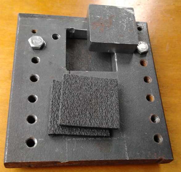
New Flat Compactor for 40x40mm electrodes
With the graphite felt necessitating compacting on the
flat, I had to make a new electrode compactor. In order that good
compaction wouldn't take 25 or 30 tons of pressure, I had to shrink the
electrode size from 64x54mm to 40x40mm, which would only require around
10 tons.
I made the steel box on the 20th and 21st, amid other
pressing work unrelated to energy projects. First I tried some 3/8"
stainless steel plate, but in order to cut the inside square a jigsaw
was required, and the stainless made short work of the metal cutting
blades. I switched to a 1/2" thick piece of mild steel (a better
thickness anyway) and drilled holes all the way around the edges so the
jigsaw only had to cut from hole to hole until the center fell out.
Then came some hours of filing to get the hole to size and everything
straight and even. This part, tho made from a previously used piece of
steel with a bunch of holes that I had on hand, is big enough to cut a
second "window" into. (It was intended that the stainless steel piece
would have four, to do four electrodes at a time. I think if I really
want a compactor with multiple "frames", I'll have it cut by CNC
waterjet
since each one is so much work to do by hand.)
The square "punch" piece for the middle, again 1/2" mild
steel, was easier as it could be cut with the angle grinder and mostly
ground to shape, with just the final shaping and squaring done by file.
Finally I found a piece of 1/4" plate for a bottom and did
a couple of threaded holes for bolts to attach it to the "frame" piece.
First Graphite Felt Electrode
The first electrode would of course be the posode with
graphite felt, made with the Ni:Mn 60:40 ratio. I showed this in TE
News #69, but
apparently I showed it with additives for the negode instead of the
plus
side. The corrected mix with the right additives would be:
Substance % % Ni or
Mn Total Ni or Mn Ratio Ni:Mn (%)
Monel 16
69.65 11.14
30.74
Ni(OH)2 17 63
10.71
29.54
KMnO4 40
36 14.4
39.72
Grafit Pwdr 20
Sm2O3 7
----
100
Considering that the monel powder was coarser and some of
the nickel would doubtless be unavailable, I decided to use a little
less KMnO4. I bought some "charcoal powder" at an art store, but it
seemed to have infinite resistance, so I stuck with the graphite
powder. This should also indicate the difference between without and
with graphite felt better, without throwing in other variables at the
same
time. The actual mix became:
Monel - 19
Ni(OH)2 - 18
KMnO4 - 32.6 (subtotal 69.8)
Graphite - 20
Sm2O3 - 7
----
96.8
The optimum proportions to use, especially of graphite
powder and samarium oxide, are only guesses.
In the absence of
any sort of special shaker machine to
get the powders to work their way into the spaces in the felt, the
first plan I came up with was to strap a plastic jar with the felt
pieces and fairly full of powder to my ankle and go for a walk. On the
23rd I cut some felt pieces to 40x40mm and mixed the powder, dry. I did
the jar, full of powder and felt pieces, but I just tapped and shook it
in my hands while I watched some youtube videos. Since it wasn't full
afterward, some of the powder must have gone into the spaces between
the fibers in the felt. I added more powder and stopped tapping
eventually after no more seemed
inclined to go into the felts.
I put two pieces of this "saturated" felt into the
compactor box, adding a little Sunlight dishsoap and Dieselkleen liquid
between
them, and pressed to about 8 metric tons (8 megagrams - Mg). That made
a pretty thin electrode, so I added a bit more of the liquids and a
third piece of the felt on top, which I then pressed to 10 Mg. I would
seem I should have used still thicker steel, since 3 thicknesses of
uncompressed felt will stick out the top a bit.
The electrode looked about the same as previous ones
except smaller
and thinner (2.5mm? - I forgot to measure it), and a little fuzzy
around the edges from the felt
fibers. It seemed pretty conductive, under 10 ohms if I dug the
ohmmeter probes in a bit, 20-30 if they were laid on it flat. The
electrode weighed 7.8 grams, of which about 1.8 would have been the
felt, so the rest was 6 or so, so under 5 of active chemicals. If one
attained 100 mAH/g that would be around 1/2 an amp-hour. If it got
anything like that with good voltage, it would be far ahead of previous
cells. I painted it with ferric chloride. (...There's something about
those recent iron electrode experiments suggesting it might be a good
additive.)
I then cut a couple of 40x40mm (plus terminal tails)
pieces of the
graphite foil to face electrodes with. I hope it's more durable than
the graphite gasket material, but it cut pretty easily with scissors,
as did the felt. I then painted one with osmium doped acetaldehyde as a
surface conductivity layer - and I suppose antioxidant layer - for the
graphite. It didn't soak into the shiny foil much so very little liquid
was required.
Next on the list of non-durables, I took apart the recent
unsuccessful cell and noted that the tail of the zinc current collector
on the negode had entirely corroded away from the electrode. I decided
to try the graphite foil on that side too. I've been meaning for
some time to see if graphite in that electrode would bubble hydrogen
and discharge it. If it does, perhaps I should look at lead (Pb)
current collectors. That would be nothing like lead in a lead-acid
battery since (in theory) the current collector will never deteriorate,
it's only a small portion of the battery, and the battery should last
indefinitely. Or it could be any metal with a lead coating.
The other electrode briquette, done rather casually on the
24th from a previous mix, again with 10 Mg pressure, weighed 13.9 grams
and
was about 2.6mm thick. Since Mn as a negative is almost an amp-hour per
gram, it'll have far more capacity than the plus side. I used the other
graphite foil current collector but didn't coat it. The graphite shouldn't
oxidize with a negative voltage on it. (Then again, I don't see why the
zinc should either. Perhaps it's forming zinc hydride, ZnH2?)
I torched the surfaces of both electrodes for a few
seconds and then assembled the cell, this time with watercolor paper
surrounding both electrodes and 3 layers of PP cloth between the
papers. I cut 2 pieces of 3/16" ABS for ends then clamped it all
together. Then I cut slits in the lid of a small plastic "ointment jar"
for the terminals
and assembled the cell, "OJC1".
Charging, testing and Performance
It started with a reading of 1.37 volts. I hooked up a
charge and it jumped to around 2.4 volts at about 25mA, then proceeded
gradually (a few minutes) downward to about 1.7 with current rising to
33mA - hopefully as electrode conductivity picked up and not as thing
went bad and shorts formed.
But it was the latter and the voltage continued to drop. I took the
electrode assembly apart and didn't see much. I added another sheet of
watercolor paper around the posode, stuffed in a fold that was
sticking out on the negode, and put it together again. This time it
was evidently okay as it started charging, painfully slowly. I upped
the current to 90mA. It took hours to get from 1.8v to 2.0. There were
bubbles and the water level appeared to be down a bit. I added more
water and increased the charge (it was down to 65mA) to about 100mA
with a smaller series resistor. It would hopefully be charging up the
oxidized zinc to metallic particles, and the plus side oxides to nickel
manganate. Would it then charge the manganese and proceed up to 2.6
volts, or would the graphite foil bubble hydrogen?
Since the active surface area of the electrodes is 16
sq.cm instead of 41, 100mA is similar to 250 mA with the larger size
electrodes, a rate at which the charge voltage would have been much too
high. Hopefully this meant the new cell had substantially better
substance utilization and current capacity, which would be due mostly
to the graphite felt, plus a little due to the electrodes being more
uniformly compacted with the flat compation. But I reduced the charge
to the 65 mA figure before retiring.
The next morning the voltage was still only 2.09 and tiny
bubbles were everywhere. I figured the graphite foil current
collector on the minus side was bubbling away the charge of the
manganese. pH was about 13 and the electrolyte was clear of purple
MnO4- ion. On the good side, a 1 ohm resistor load only
dropped the voltage to 1.3, ie, this small cell was sourcing 1.3 amps.
That's about 80 mA/sq.cm, which is a good figure and about four
times better than my previous cells. Doubtless that will be matched by
at least a similar rise in active substance utilization. It also shows
that the posode was definitely limiting the current. The negode,
charging to metallic state, should be highly conductive in theory, and
evidently in practice. Zinc is a known high current electrode, and the
manganese with the 20% zinc powder additive is probably similar.
I took the cell apart and replaced the graphite foil
negode current collector with a zinc one. It didn't seem to help.
Perhaps I had been premature and the cell really was taking that long
to charge. The plus side would have finished charging and would bubble
as the negative shed hydroxide. If that was what was happening, it
would mean it had good amp-hours in the negode. Theoretically it has
over 10 amp-hours of substance, and it might have maybe 5 to 10 in
actuality, so actually it should take many hours to charge at .065 amps
current.
Then I found one of the aligator clip leeds with a rusty
clip had a bad connection. (The clips corrode easily and frequently
doing salty battery tests. Salty moisture creeps up the electrode
terminals unless well sealed, and you can't seal them if you might want
to take the cell apart again. I do buy new clip leeds occasionally, but
I don't
seem to be keeping up.) With the clip flexed around a bit, the voltage
started to rise rapidly (a few minutes) over 2.3 volts. Now... was the
original problem the graphite collector, or the rusty aligator clip?
The voltage
wouldn't go up to the now expected 2.6 volts. Nor did putting the cell
in the fridge seem to help. About 12 hours of patience however revealed
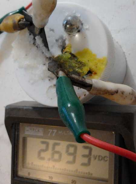
that it was in fact slowly rising and it neared 2.4 V on charge, and
the next morning (26th) it was over 2.5. It also put out around 1.6
volts/1.6 amps into one ohm for a few seconds, for 100 mA/sq.cm of
electrode interface - yay! The previous top was at best about 20-30
mA/sq.cm.
I had put the cell in the fridge, and I now took it out to
verify that the Mn would hold its metallic state charge at a higher
temperature. (I should put it in warm water to try higher
temperatures and find the limit.) It worked, but the self discharge
went up. I was
concerned by the self discharge, until I finally remembered it drops by
itself over a few weeks.
Graphite Foil Negative Current Collector Works!
When the voltage was finally up, the performance in a
discharge test seemed to be way down. I had to do 50 ohm load tests
because 10 ohms was now an overload - the voltage dropped rapidly with
10 ohms. Once again, promising initial results seemed to deteriorate -
but when size was accounted for it still seemed better than previous
cells. Later I suspected that in taking the stack apart after it was
wetted, twice, I had permitted the electrodes to expand somewhat,
losing internal conductivity and hence performance. Assuming I didn't
allow that to happen again, future cells should live up to the initial
performance of "OJC1".
I took out the zinc current collector and put the
"Sigracet"
graphite foil one back in. I have been meaning to test and see if
graphite materials in the negode would could self discharge for quite
some time now. It worked. This was good news as I have lost all
confidence now in zinc current collectors.
Performance was even poorer. So I took the graphite sheet
out, cleaned it, and painted the contact surface with osmium doped
acetaldehyde. The main problem turned out to be that I hadn't recharged
the cell very long after taking it apart, but it still wasn't as good
as before I'd replaced the current collector the first time. I probably
got better contact to the first current collector. (And the electrodes
had probably swelled while apart.)
The next test, after several hours charging, went better.
And with no zinc in the current collector (albeit zinc powder as a
conductivity additive), it shouldn't matter much to the cell how far it
ran down. I decided to run the test longer and see if the voltage would
level off somewhere. I was about to quit at 1.7 volts when it started
leveling out, soon dropping by only about 3 to 6 mV/minute in the 1.69
- 1.55 volts range, and the cell ran for an hour. Below 1.55 volts the
rate of drop increased again and I stopped at 1.48.
I figure in the higher voltages the posode went from
NiMn2O4 (nickel manganate) to nickel hydroxide and manganese dioxide
(~+.9v?), and in the lower range the manganese went to Mn2O3 or MnOOH
(+.2v). Further still lower voltage ranges should occur as the Mn goes
to Mn3O4 (-.1v) and then to Mn(OH)2 (-.3v). The other electrode should
contribute a fairly steady voltage (~-1.4) to the total, since it has
substantially more substance.
With a 50 ohm load and current dropping with voltage, the
cell still only delivered about 35 mA-H, far below the moderate
expectation of 500. And why had the current capacity dropped so
markedly? Could the graphite felt be deteriorating? Should I have
dipped it in osmium doped acetaldehyde? Or, would carbon black help?
I noted that a fair amount of Ni(OH)2 had come out of the
electrode. Perhaps next time I should try a simple "book" fold with the
watercolor paper, and then seal the other three edges with wax. The
'origami' paper folding often doesn't seem to work out very well.
Or could the negode be the problem? That was the part I
had disassembled and replaced the current collector of several times.
It was in several broken pieces with bits at the bottom by the time I
had finished. It may be that it now had few contact points with the
current collector in spite of clamping the electrode assembly together
fairly strongly.
But, now that it was determined that graphite doesn't
prevent it from holding its charge, perhaps graphite felt in that
electrode as well would raise performance? It should certainly improve
things a lot if there was spotty contact between electrode and current
collector.
Again, the later thought that the electrodes had swelled
seemed the most likely explanation.
 On the 28th I
ran another discharge test. Initially it
went about like the previous one. But when the voltage dropped below
about 2.1 volts, the rate of dropping continued to increase more and
more without slowing at any intermediate levels. Thus it only ran 1/2
as long, 29 minutes, "full voltage or nothing". It only ran 4 minutes
below 1.7 volts, falling from 1.443 to 1.160 volts in the last minute.
On the 28th I
ran another discharge test. Initially it
went about like the previous one. But when the voltage dropped below
about 2.1 volts, the rate of dropping continued to increase more and
more without slowing at any intermediate levels. Thus it only ran 1/2
as long, 29 minutes, "full voltage or nothing". It only ran 4 minutes
below 1.7 volts, falling from 1.443 to 1.160 volts in the last minute.
Overnight the charge voltage went up from the previous 2.8
volts to 2.9 volts, and on the morning of March 1st there was a smell
of chlorine in the lab. That would be the Cl from the KCl charging to
gas. The negative side was wicking up white salt (& hydroxide)
forming large white crystals
through the unsealed terminal slit, while the positive side had
creamier looking yellow stuff. (salt + sulfates?) Evidently 2.8 V
should be the charge
voltage limit to avoid loss of chloride from the electrolyte.
In the next test (again 50 ohm load) the voltages were up
a little, the bulk of the discharge curve being in the 2.2x volt range
instead of 2.1x. There was something of a voltage drop slowdown through
the 1.8x volt range, but nothing like the 'steady state' near 1.6x of
the earlier test. The cell ran 39 minutes instead of 29. The
overcharging doubtless contributed, but hopefully as self discharge
decreases the amp-hours will also continue to improve. Another test on
March 3rd yielded almost identical results, and two on March 5th & 6th
drove slightly higher voltages yet for a 30% longer
run time - from almost 2.4V (after 1 minute) down to 2.0V (@36'). And
this cell won't die after a few weeks from a zinc current
collector corroding away until it falls off.
My theory for the change in discharge behavior is that
once the nickel manganate has formed during charge cycles, the
manganese doesn't detach from the nickel again during discharge to act
as an independent oxide. Nickel manganate evidently consists of a
variety of related compounds, generically stated as NixMn(3-x)Oy
, or presumably NiMn2O4 and Ni2MnO4,
and
some
with
fewer
oxygens,
perhaps
NiMn2O3 and
Ni2MnO3. It's probably the oxygens that come and
go as the electrode charges and discharges:
NiMn2O4 + H2O + 2 e- <--> NiMn2O3 + 2 OH- [~ +1
V]
It may be
noted that experimenters at Sanyo, using the
nickel hydroxide and manganese combo, used equipment that determined
there was nickel charging to "average valence up to 3.8". They
attributed this to "oxygen overvoltage raising" by the manganese to
allow the nickel to form "alpha nickel oxyhydroxide". There was no
mention of what the manganese was doing, despite the fact that
manganese oxidizes at a lower voltage than nickel, and that formation
of slightly soluble KMnO4 during charging is undesirable (as has been
gradually beat into my head through experiments, notwithstanding
chelation and notwithstanding that using KMnO4 is a good way to
initially make the electrode). NiMn2O4 could perhaps have nickel at
valence 4. Such observations and measurements are a whole field I don't
want to get into myself and requiring electron microscopy equipment and
knowledge, but I think probably they
weren't looking for the right things to find the right explanations of
the chemistry. (Especially given that they were trying unrelated metals
as well and only picked Mn because it "worked best".)
I sealed the slots
up with heat glue on the 2nd to continue testing of this cell
longer term. I'll make a new cell to try further things like graphite
foam in both electrodes and wax edge seals. Another thing to try is to
clamp the stack together more strongly, to prevent expansion of the
electrodes... and to not take it apart once made. I suspect that may be
the reason for the performance
degradation after taking the stack apart to change current collectors.
Tentative Conclusions
With the graphite felt and the seemingly impervious
graphite foil, which contains some sort of polymer making it
technically some sort
of highly conductive composite, and the elimination of the corroding
zinc current collectors, the cells are now actually usable and I think
can be expected to last a long time, and I hope developing technique
will render them better and better until
they start living up to the theoretical promises of the chemistry.
http://www.TurquoiseEnergy.com
Victoria BC