Turquoise
Energy Ltd. News #74
March 2014 (posted April 1st)
Victoria BC
by Craig Carmichael
www.TurquoiseEnergy.com
= www.ElectricCaik.com
= www.ElectricHubcap.com
= www.ElectricWeel.com
Month In Brief
(Project Summaries)
In
Passing
(Miscellaneous
topics, editorial comments & opinionated rants)
* Hit squads murdering ForEx traders and other banking executives who
'know too much'.
* Coast Capital Savings: a rigged election and the need for the choice
ranking vote and for an independent member communication vehicle. (How
about "CCS-governance@yahoogroups.com" ?)
Electric Transport - Electric
Hubcap Motor Systems
* Thinking again about centrifugal torque converter: A weighty missing
piece: a flywheel !!!
* Mazda RX7 update: weather effects; battery monitor
* 100 amp-hour NiMH D cell battery for electric car (installed in
electric Mazda RX7)
* 200 amp-hour Lithium-Ion cell battery for Electric Caik Outboard
* Supercapacitors start cars!
Other "Green"
Electric Equipment Projects (No reports)
Electricity Generating
* Solar Panel east-west facings to extend daily collection period
* Glass texture idea [just mentioning it again] to extend and increase
daily solar collection
Electricity Storage - Turquoise
(NiMn) Battery Project etc.
* "Carbon Black" from charcoal
* Nasty self discharge with the charcoal: the nitrAte-NitrIte shuttle?
* Probably the graphite powder is also impure - could explain ALL the
self discharging!
* Video: How to make open cell graphitic carbon foam (purest "carbon
black"? and potential replacement for carbon felt?)
No Project Reports on:
Lambda Ray Collector, Magnet motor, Pulsejet steel
plate cutter, CNC Gardening/Farming Machine (sigh, maybe summer 2014...
2015?),
Woodstove/Thermal Electricity Generator (will probably abandon),
evacuated tube heat radiators, individual EV
battery monitor (will probably NOT cancel this).
Newsletters Index/Highlights: http://www.TurquoiseEnergy.com/news/index.html
Construction Manuals and information:
- Electric Hubcap Family Motors - Turquoise Motor Controllers -
Ersatz 'powder coating' home process for
protecting/painting metal
- Preliminary Ni-Mn Battery Making book
Products Catalog:
- Electric Hubcap 4.6KW BLDC Pancake Motor Kit
- Electric
Caik
3KW BLDC Pancake Motor Kit
- NiMH Handy Battery Sticks, 12v battery trays & Dry
Cells (cheapest NiMH
prices in Victoria BC)
- LED Light Fixtures
(Will accept BITCOIN digital currency)
...all at: http://www.TurquoiseEnergy.com/
(orders: e-mail craig@saers.com)
March in Brief
In March I had the SR & ED report to make, so there
was bound to be less progress on energy projects. But I also started in
on some non-energy projects around the house that I've been putting
off, and collected some firewood for next winter. Such things seemed to
take up much of my time. I didn't even get going on the vital report
until the 14th, and then worked on it only fitfully and didn't get it
half done. Yikes!
I made some 'carbon
black' powder from charcoal for a battery electrode. When I finally
made an electrode with it it worked badly and wouldn't hold a charge.
It seems charcoal probably has nitrates in it. But owing to that, I
realized impure graphite with just a few nitrates - after all it's from
an 'artists supply' source - is probably what's been causing the self
discharge that has cursed my cells all along. With that thought, I'll
now try something else.
While cleaning up a pile of lumber I ran across the
shattered solar collector that fell from the roof when I was installing
them a couple of years ago. I had set it on a piece of plywood and put
it in the pile. In the sun it still put out 35 volts, and I decided to
try and mount it on a low porch roof with a west facing slope, to get
more power until a little later in the evening. It's working and the
total is now about 1100 watts of collectors. It still won't charge the
Mazda at 300-400 watts except in full daytime sunlight. Another
collector facing west and a couple facing east would start lengthening
the collection day some, and maybe allow charging the car during light
overcast, which has been preventing it almost every day in the later
part of the month.
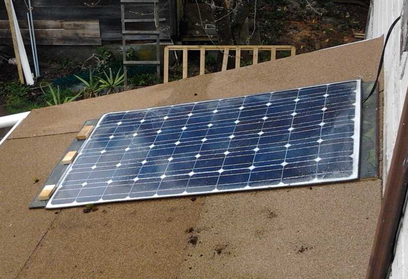 Shattered solar collector placed gingerly on a
low roof
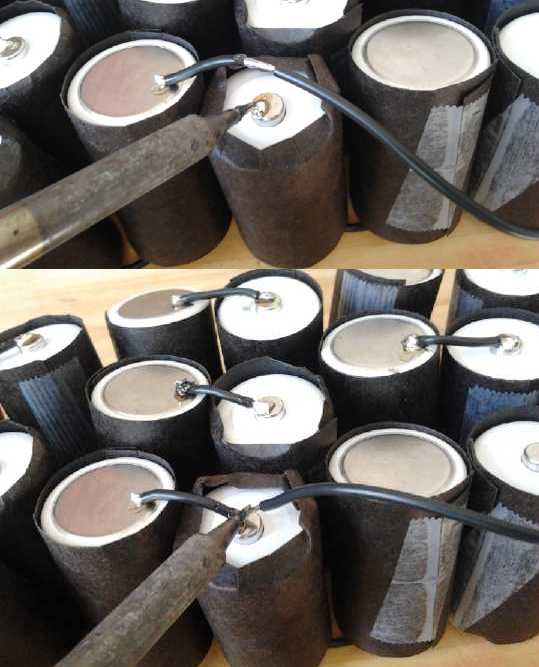
I soldered together 100 D cells for a 100 amp-hour NiMH
battery for electric transport. I made the battery as two 50 amp-hour,
12 volt wooden boxes. I installed this in the electric Mazda. I had to
move chargers and cords to put it in, and had some trouble with
unplugged chargers that could have resulted in ruined batteries if I
hadn't been vigilant.
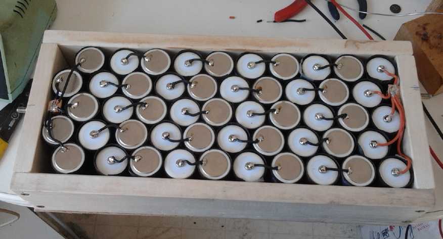 50AH, 12V NiMH battery
I decided that the individual battery monitor with a
voltage bar on the dash for each battery is after all a pretty vital
component, since the problems, which would quickly become serious,
would have shown up on the the display
and not just because I suspiciously spent time after each trip manually
checking each individual battery's voltage.
I've also bought some lithium-ion cells to run the boat
with the Electric Caik outboard, with an eye to actually going out on
the ocean, for longer tests - and maybe even doing some fishing. The
configuration will be 200 amp-hours, 17 volts, since I couldn't use
full throttle at 24 volts without risk of over-revving the motor. Some
smaller solar collectors I have have about the ideal voltage to charge
the lithiums, and I might contrive to mount one or two on the boat
somehow.
On the conceptual side, I think I've pinpointed the reason
my centrifugal torque converters haven't been successful: They need a
flywheel to keep the motor speed from suddenly dropping when delivering
each 'torque hit' to the drum. The energy is going into slowing the
motor and twisting the housing, vibrating the car without imparting
sufficient force to the drum to get the drive train to start turning.
Once again I've been driving a spike with a tack hammer.
I've bought some parts for a new attempt, in which I have
more expectations of getting the car moving, but which will take
considerable rebuilding of the transmission mounting box.
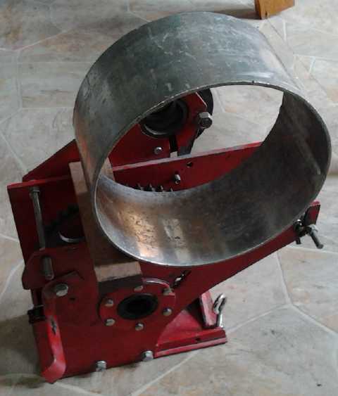 New drum: 3/16" thick walls, 10" diameter by 5"
long.
The mounting will need considerable reworking.
In Passing
(Miscellaneous topics, editorial comments & opinionated rants)
A new class of at-risk people: bankers?
A month or so ago, it leaked out through the internet news
that four banking executives had "committed suicide" in London and
Tokyo. Someone dwelt on the great pressures these people face in their
vocations under the facade of great wealth. But comments under videos
showed that not many people believed "suicide" was the cause of death.
Before the end of March, the number had risen to twelve or more in
locations around the globe, and people "committing suicide", for
example by repeatedly shooting themself with a nail gun - and with not
one leaving a suicide note - was getting hard to swallow.
It became apparent that "hit squads" are being employed to
systematically murder banking executives. What's the motive? Is there
some common link?
It developed that the majority of the victims were
employees of JP Morgan, the largest bank in the USA. Furthermore, it
seemed that most of them, whoever their employer, had been involved in
the "forex" ("Foreign Exchange") trading markets. (Hence their diverse
locations?)
And finally, that there is a major criminal investigation
instigated in (IIRC) Germany into the rigging of the forex markets.
This may be different from the many "civil" fraud investigations in the
USA and the UK resulting in fines of billions of dollars - a token
fraction of the wealth the frauds have scammed from victims, and
without
any punishment of the actual people committing the frauds. Much or most
of the wealth of the middle class has been stolen, yet no one has gone
to jail and all are free to continue their pillage.
Deutsche bank quit the forex management system, and people
there (at least one victim was from Deutsche bank) were apparently
starting to co-operate with the investigators. This might have led to
the arrest of even the scoundrels at the center of the web, such as
perhaps Rothschild and Rockefeller family members.
Apparently killing all the witnesses, all the people who
"knew too much", was the preferred method of handling the situation.
Or, perhaps, it has nothing to do with this or any
investigation.
Perhaps some of these people just wanted to warn the public about the
collapse that's coming, and such 'suspect' people were murdered just in
case. There have in fact been such warnings from banks in recent weeks.
(Some youtubers think there may be very little time left to prepare.)
Or, perhaps some of the victims of the rigged ForEx
trading markets
decided to seek some sort of redress against the banksters outside the
kangaroo courts where they are never tried. But if so, they are
certainly
well organized, and somehow had access to the JP Morgan buildings from
which some of the victims fell.
Whatever the motive for these heinous and ruthless
murders, they may
not be over yet. Near the end of the month there was an article about a
cyclist killed on his bicycle by a vehicle. He was thrown 125 to 150
feet in the collision - in broad daylight on a wide road. This raised
red flags to one youtube journalist. He found an obituary, again heavy
on the fact that the man was an "avid cyclist" and the sensational
details of the collision, but little other information such as how it
happened or what he did for a living. Where was the driver of the car?
Digging
further into the name, it turned out the cyclist was the head lawyer
for JP Morgan bank.
A Corrupt Election: the need for the choice ranking vote
A ballot came in the mail for voting on several member
resolutions and election of three new directors at Coast Capital
Savings Credit Union, of which I am a member. This followed on an
annual general meeting at which some members obviously didn't like
the way things were being run.
I've become suspicious in the last 2 or 3 years that
the Coast Capital management is corrupt, like in so many other
financial institutions. There's been a vacuum of information from them
for years - no newsletters or anything beyond what they're probably
absolutely legally required to send. I looked rather carefully at the
information pamphlet and the ballot. The information pamphlet said as
bluntly as it could without actually giving direct orders: "We are
required
by law to present these resolutions, against our wishes." "Don't let
special interest groups push their agenda on our credit union." "It's
working great as it is." "Vote
as we recommend."
For each member proposal there was an alternative proposal
by the board of directors, and a statement that these would supersede
the member proposals. What?!? What business did the board have trying
to alter every proposal put forward by the members? Then, I found no
descriptions in the booklet of either the members' proposals or the
board's alternatives. It was "Vote how we ask. Trust us."
And I talked to a teller, who said she would take the
board's pick over whatever members had come up with. Clueless! I
suspect that she is in a majority or at least a large minority. Follow
the money: the CCS board awards itself double what the Van City Savings
board does, and Van City is a substantially larger credit union.
Then there was the election of new board members. There
were 12 candidates, with three to be elected by three "X"es. That may sound
fair and impartial, but look more closely. The present board
recommended three and only three. Some of the other nine had impressive
credentials, and none looked like people you wouldn't want to have in
charge.
The unfairness, as usual with the single ballot
"illiterate's X" vote, is subtle but far reaching in its effects.
Suppose that even 70% of the members,
like me, didn't trust the present board. That means we assume that the
"recommended" candidates were hand picked to continue the
present secretive and lucrative regime, and continue blocking member
input. (70% would be
amazing. It's hard to wake up a pile of people who have no vehicle of
communication between themselves other than the newsletter put out by
the board. But let's take it at that.) Just 30% trust the board and
will vote as it suggests. One would expect that if 70% disliked and
mistrusted the present board, big changes should be in the offing when
the votes are counted.
But what is really going to happen? The 30% will all cast
their three "X" votes for the board's three hand picked
candidates.
30% / 3 candidates = 10%
10% * 3 votes per member = 30% for each of the three 'picked'
candidates.
The other 70% of the vote will be split between the other
nine candidates. Unless one or more of them stands well above the rest,
the votes, cast by members who mostly don't personally know them, are
apt to be split rather evenly.
70% / 9 candidates = 7.8% each
7.8% * 3 votes per member = 23.3%.
The three "recommended" candidates are thus likely to
all win even if 70% of the members would rather have any three of the
other nine. Plus, since members who are dissatisfied are likely to
close their accounts and leave, 70% is probably an impossible
percentage of dissatisfied members to obtain under any realistic
circumstances. Thus it can be seen that the membership has virtually no
chance of electing more trustworthy people. We are at the mercy of the
present board and its hand-picked successors.
I suspect that the board went out of their way to find so many "other"
candidates to split the vote. I keep two Coast Capital accounts open
for strategic purposes but
I no longer keep much in them. In essence I've already "voted with my
feet" and left.
With the choice ranking vote, if just 51% of members
distrusted the present board, they would rank the nine independent
candidates in some preferred order from one to nine, and the three
board-picked candidates last: 10, 11 and 12. The nine would then have
precedence. The most popular three of
them would win and the (probably corrupt) board's hand-picked
candidates would lose. It would allow for a more real democracy instead
of
skewed, manipulated democracy. That's a game changer.
Writing this has also suggested to me a means to correct
the fact that the members have no free and open communication vehicle:
start an e-mail discussion group or a blog of some sort. It would be
another game changer for members to be able talk to each other in a
forum. Those proposing changes could freely make their case with
feedback from other members, knowing that the subjects of the dialog
couldn't edit or refuse to print their words. I will not be
the one to create this forum as my plate is already overflowing.
I joined "Westcoast Savings Credit Union" in 1977. On
recommendation of both boards, this was merged with "Pacific Savings
Credit Union" long ago to make "Pacific Coast Savings Credit Union".
Finally, again on recommendation of both boards, this was merged with
"Surrey Savings Credit Union" (IIRC the name) to create "Coast Capital
Savings", BC's second largest credit union and now largely under
mainland control, shutting us on Vancouver Island out of the running of
'our' institution.
Without actually knowing, I suspect that with each merger,
the bylaws were rewritten by the boards to give themselves freer, more
secretive reign
and relieve the members of effective control over 'our' institution.
I suspect the present board is now very much afraid of
having even a single independent board member elected. That would
disrupt their greedy little party, and perhaps result in them
being turned over to BC's financial regulatory authorities to account
for past activities.
Electric
Hubcap Motor Systems - Electric Transport
Centrifugal Torque Converter
(again!?!)
When I found in
February that I couldn't easily add a stock centrifugal
clutch to the planetary gear converter to get it working, my thoughts
turned
again to the centrifugal type converter. It's a wholely simple concept,
but I haven't had much success with it. Now I realize there's a tricky
piece I've been missing.
A missing piece to the puzzle: a flywheel
A newly considered aspect in keeping with a converter
making "torque hits" rather than a continuous sort of conversion is the
need to add an inertial weight, a flywheel, to the motor rotor, to
smooth out the motor speed. With my previous converters and especially
the last one, the motor slowed markedly with each hit - it nearly
stopped at times. The motor of course has its magnet rotor and the
rotor with the centrifugal shoes, but they're not enough weight. With
substantially more mass
behind those hits, it would probably have made more forward motion and
wasted less energy in uselessly shaking the car. With little flywheel
weight, much of the force of each hit was spent in suddenly slowing the
motor and twisting the transmission box backwards, instead of suddenly
pushing the drive shaft forward. That motion, transferred through the
mountings to the car, would be the force that caused the whole car to
shake.
Herein I finally recognized the fundamental problem: I had
again created a tack hammer instead of a sledge hammer, to hit a large
spike. The hammer was bouncing back and the spike wasn't going
anywhere. With weight behind the blows, a good flywheel weight, the
motor would keep its speed relatively constant, everything would be
much smoothed out, and much more force would be transferred to the
output shaft with each blow.
Next Design
In a centrifugal clutch
much energy goes into making
heat while it's slipping. Evidently they get hot. It's inefficient, and
only the short duration
of the slipping until it's locked on as RPM increases makes it workable.
With a drum the size of, say, a clothes
drier drum, a rather light touch from the shoes would boost a car
into motion - the drum size itself is a sort of "gear ratio". With the
present
4 to 1 chain reduction following the converter, the Chevy Sprint would
be easily moved simply
by turning such a big drum by hand. But surely such a size would be
overkill.
The strong blows of the centrifugal converter I made a
couple of months ago
with wide slots and big plastic shoes would probably have got the car
going if it had had a flywheel. That aside, the plastic shoes were
being chewed up. I consider the inside diameter and
the width were both too small, and I started thinking again of making
it all larger diameter and much wider: 10 to 12" diameter, and inches
long slots with matching shoe widths. I would also make many narrow
slots again, so that the individual vibrations would be much reduced,
but it should still act to make sudden forces on the drum with spaces
between them, rather than a continual drag making heat like a
centrifugal clutch.
What would be an optimal - or at least workable - drum
diameter and width? At some point of size, masses and shoes, the device
would
have to act as a sufficient centrifugal clutch to move the car, with
sufficiently light internal forces that it wouldn't self-destruct. And
pointed shoes should make rapid-fire torque hits at the many slots,
rather than just rub and make heat all the way around the drum. Thus in
theory, if one can get the design 'right', it might well be the best
possible type of torque converter.
To accommodate this wide drum, I'll have to modify the
transmission 'box'. For the drum itself, I thought I'd look for a
10-12" aluminum pan with straight sides. Or maybe an aluminum pipe with
thick walls. That would be the piece to have before starting any other
work on it. I had looked around for a 10" pipe for the previous attempt
but only found an 8" piece, 3" long, and decided it was too small.
I started thinking that if I could find something larger
with 1/4" thick walls, or maybe even 5/16ths", perhaps I could cut the
slots as
"V" grooves on the inside and not go right through the walls. Obviously
this would be stronger. If only the 8" x 3" pipe piece was 10" x 4 or
5"!
I called Metal Supermarket, and they suggested having a
flat piece of aluminum bent into a sleeve and getting the seam welded.
This actually sounded like a workable plan. But rather than have
someone do it as a custom job for each attempt, I thought it might be
better to see what kind of a deal KMS tools had on a small metal bender
- it just might cost no more, especially if it took more than one
attempt. If I cut the grooves first and then bent it, it would be
easier and the bender could perhaps be a lighter unit. And since only
the inside has to be smooth, perhaps one end could be bent into an
overlap to fit outside, and flat head bolts put through from the inside
to avoid having to do an aluminum weld. In fact, as I'm joining
Victoria Makerspace... perhaps they have a metal bender? And aluminum
welding equipment?
Someone else thought it would be hard to get it really
round, and it would be too big to turn on my lathe.
 Aluminum pan converter drum?
Late in the month, I was passing by a big store
of used things. I went in and looked at the pots and pans section.
There was a heavy aluminum pan just over 10" inside diameter with
vertical sides (despite the appearance in the image), 4.125" tall, and
1/8" thick metal. Of course I bought
it - it was close enough to what I had in mind for the drum. On the
other hand, how was I to cut the slots? Down near the bottom of the pan
it would be hard to get any tool in. And would it turn true? - the
bottom wasn't made to take such forces and it was already warped. These
were potential large problems.
I thought again of a 10" wide aluminum roller I had seen
at Smith Bros foundry. I had thought to buy a 5" piece off the end. On
the 29th my thoughts turned to buying the whole 3' long roller complete
with its inner ends and centered bearing pieces. On Monday April 1st I
settled for the 5" end, leaving the rest for some slightly shorter
roller. The metal was thicker than I thought, 3/16" - thick enough to
score grooves in rather than slit right through, which was exactly what
I'd wanted. The rounded end had fooled me the first time I looked into
thinking it was only 1/8".
 10" x 5" drum, 3/16" aluminum, on the
transmission box, which will need considerable modification
Electric Mazda RX7 - NiMH battery for
electric car -
Battery Monitor is back ON
This winter I've noticed that the RX7 definitely uses more
elecricity per mile in cold weather than in warm. With ten batteries
(120V), it goes as high as about 3 amp-hours per mile when it's
freezing, but only 2.6 when it's warm.
The only explanations for this I can come up with are that
the transmission oil, differential oil and wheel bearing grease are
thicker and causing more friction, and that the tires may lose pressure
in cold weather and have more friction. (I didn't think to check tire
pressures.) If it's largely the transmission oil, that would bode well
for getting substantially increased range by bypassing the transmission
entirely with an efficient torque converter - as is pretty well known.
 On the 17th I
thought again of the Mazda with its meager
range further reduced by having only 10 batteries, and also of the NiMH
D cells I had bought months ago to make up EV batteries and other
battery packs from, still sitting unused.
The price of the cells is a little too high for most
potential custormers, and it's gone up substantially, mostly because
Tenergy/All-battery.com no longer will ship by the post office and the
cross-border delivery and customs charges by courier companies are much
higher.
I decided I'd make up a 100 AH battery by soldering up a
pack. I knew it would take hours, but to my surprise it took pretty
much two full days. There was nothing really unforeseen about doing it
or the
basic results to be expected, but it was a lot of soldering and
repetitive slogging along to put together 100 D cells in two wooden
cases. I think the battery pipes - "giant flashlight tubes" - are
probably less work to put together, as are the 3D printed battery trays.
(I have in mind using this excellent battery in the
electric Chevy Sprint if I get it running, which seems more hopeful now
with the flywheel idea for a centrifugal torque converter.)
In the process I improved my battery pack assembly
techniques some. Of course I kept the tarpaper wrappings to ensure that
hot cells could never melt their plastic and short their cans together.
First, I found that instead of making a frame to hold the
cells or having them loose and falling over, I could just line them up
in a row in the battery boxes for soldering.
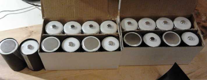
Second I switched to #18 stranded wire. The lengths are so short
there can be little voltage drop even at high currents, and thinner
flexible wire is less likely to break away from the solder. When
stripping the wire, I strip enough insulation off for both ends, then
use the strippers to slide an appropriate length of insulation toward
the end so there are two bare spots. I then solder one end to one cell,
and the middle bare spot to the other. This allows me to hold the wire
with my fingers well away from the hot solder spots. Once the second
spot is soldered, then I cut the wire off.
When installing this battery in
the well in the back of the car, I had to move some chargers and their
wires
aside. After the next drive I found the new battery was low - it hadn't
had enough time to charge up. After one more drive I thought voltages
seemed a touch low and decided to check things out. I found another
battery was down: it's charger hadn't been plugged back in. After
another drive or two I checked again and found still another battery
was down to 12.0 volts. It's charger had been moved to a stressed
position and the CAT plug had pulled out (despite supposedly being a
'click lock'
plug).
With any of these problems, I could have gone one more
drive or two and driven the battery in question down into the damage
range. Only being vigilant and repeatedly checking things out after
driving prevented trouble. Of course, with an individual battery
monitor
showing the state of all the batteries on the dash, I'd have seen each
problem at a glance and they wouldn't have a chance to get serious
before action was taken. Thinking that cars are going to run on
batteries for some time rather than Lambda ray collectors, I'm again
expecting the monitor to be a valuable EV asset that I should make.
I did see one battery monitor, on a home converted
electric
motorcycle. The rider could read the state of each of the four 12V
batteries. I didn't like that there were no graphical bars, only
numbers, and it did a more limited number of batteries. One has to
think about numbers, whereas seeing a bar that's shorter than the rest
is a quick clue-in that that there's a problem. But, seeing there's at
least this one type available, I should
probably do a search and see if what's wanted is already available
before putting design effort into making one.
Lithium-Ion
Batteries For Electric Caik Outboard
On the 29th I arranged to
buy a set of eleven 100 amp-hour lithium batteries; 36 volts. These I
plan to divide into two sets of five (with a leftover) to make a 200
amp-hour, 16 to 18 volt set for the Electric Caik Outboard. I plan to
set up the 14' aluminum boat with this and go fishing this summer,
which will also give the motor and system a longer 'real-world' test. I
hope to put a solar panel or two on board to help charge the batteries.
I have three "12 volt", 90 watt panels, which actually put out around
21 volts open circuit, and will do 18-19 volts supplying good current.
That's probably a good "float charge" match for the lithiums without
even a regulator.
If the current is still a little too high when they're charged, a diode
or two in series will make it right.
Supercapacitors Start Cars!
I visited a friend who
showed
me you-tube videos of supercapacitors being used in place of car and
small truck
batteries. This was an eyeopener to me. We keep hearing about
supercapacitors, but I didn't know one can now actually go out and buy
capacitors in the hundreds of farads range, economically, from common
electronic supply sources like Digi-key. The ones shown were rated for
very low voltages such as 2.5V,
and six were used in series to attain 12V capacity. In one video 300
farad capacitors were used, in another, 1200. Dividing by 6, those
would make 50 and 200 Farads. A farad holds just an amp-second of
electricity, but they supplied so much current so fast that the pick-up
truck (same one in both videos) started almost instantly every time,
and without the capacitors losing too much voltage. They even had
several starts in them, and they charged back
up in seconds.
I have my misgivings about replacing batteries with
capacitors. They certainly wouldn't run the radio - or even a clock or
modern vehicle control circuits - for long with the engine off. A solar
panel on the roof will however charge them up in minutes for the next
start if they've become discharged.
There's also the possibility that the starters and their
gears might not last long. They're designed for "typical" operating
conditions, and a system that doesn't lose voltage getting things
turning will put more stress on them.
Another misgiving is that the voltage they charge up to
depends on the car's charging system. Some cars depend on the load of
the battery, and they just might up the voltage until the capacitors
blow up, and then proceed to hundreds of volts, frying the car's
wiring. (Probably newer cars are better protected against this than
older ones?) A problem with capacitors in series in general is that one
(with the lowest leakage) may charge to 5 volts while three others
charge to 1 volt each. The total is 8 volts across four capacitors, but
one capacitor has double its rated voltage across it and could blow.
The datasheets should be checked to see if this problem is anywhere
addressed internally. Probably ~2.4V volt zenor diodes could be placed
in parallel with each capacitor to prevent overvoltage if necessary.
(If I were manufacturing the supercapacitors, I'd put zenors in them
internally.)
A modified arrangement might be to put capacitors in
parallel with small capacity battery cells, for example with a single
10 amp-hour NiMH D cell set. The battery would hold substantial charge,
and the capacitors would provide the starting current. Some vehicle
charging systems might still overcharge such a small battery.
Electricity (Energy) Production
Extending Daily
Solar Collection Period
 I
soon noticed that although south-facing provides the
maximum daily solar collection (in the northern hemisphere), in the
early morning and in the evening the sun is up but essentially not
shining on the collectors. This leads to the thought that having some
collectors facing southeast and some southwest would in fact provide
more 'bang for the buck', and for a longer period of the day. Since
that's not possible with my roof slopes, I thought it might be nice to
have additional panels, some facing east and some facing west, to
extend morning and evening collection hours.
When I put solar PV collectors on the roof a couple of
years ago, one was dropped from roof level to the ground and the glass
shattered into tiny 'safety glass' pieces. But the actual collector
elements are glued to the glass and held the pieces together, and it
still worked. I removed
it from its frame and gently set it on a sheet of plywood, and put it
on a pile of lumber, under cover.
On the 26th I was using up the lumber and pulled out the
collector. I decided I
would put it on a west facing roof slope, where the other panels face
south. I tenderly put it on the back porch roof - easy to reach, not
too steep. This seems to extend the collection period a little while
into the evening. It also raises the total system capacity from 892
watts to 1000-1100 depending how much light is being reflected away via
broken glass edges. If I get up the nerve, I may raise the delicate
piece to a steeper angle and up to a higher roof.
Another thought, as the price of solar panels continues to
drop towards a dollar a watt, is to put a panel or two on the east
facing roof slope to get collection started earlier in the morning.
Another passing thought is to try and separate a few
elements from the shattered glass and attach them to a piece of glass
made with the nanocrystalline titanium dioxide borosilicate glaze frit
sprinkled on the surface. This glass would be re-fired to melt little
pebbley 'lenses' into the surface of the glass, to prove the concept of
greatly improving daily collection by having light at oblique angles
strike the lenses (at steeper angles than for flat glass) and get
refracted into the collector instead of reflected off of it. This glaze
that I created is detailed in much earlier issues of Turquoise Energy
News. I felt by intuition that it should have potential uses in solar
power, but it was only later I realized this would be the really
excellent use for it. Much effort has gone into making the PV elements
themselves more efficient, but here is a separate way to improve the
effectiveness of any given PV elements.
Electricity Storage
Turquoise Battery Project
OJC1 Continued Performance
The performance of OJC1 stayed roughly constant. Since
cells I've made that would supposedly deteriorate over 'many' many
cycles
never seemed to last long, perhaps it has the perpetual performance
I've been expecting theoretically.
Unlike previous cells, the self discharge remained high.
On the 9th I changed the electrolyte. There was no purple permanganate
color, but lots of black and turquoise particulate sludge - stuff
escaping from around the edges of the posode. That seemed to make it
considerably worse. Probably unscrewing the lid and twisting everything
around had disturbed things - ugh! Next time: several more layers of PP
cloth between the two electrodes to hold them farther apart, as well as
wax sealed edges. (Later I remembered I had bought some coarse macrame
cloth to give the electrodes good separation and space for air bubbles
to come out.)
Posode with Carbon Black instead of Graphite Powder
 The idea of
"carbon
black" instead of graphite powder sounded enticing, but getting hold of
some of a suitable nature might be tricky... unless perhaps it could be
made from some
common carbon substance such as charcoal. I wasn't sure how that might
work, but it occurred to me that methyl benzene (toluene) or tri methyl
benzene (an ingredient in "Diesel Kleen"), might dissolve the
"partly oxidized carbon" charcoal substance, and it might solidify in a
desirable conductive form when the liquid evaporated. Or, regardless,
it might convert to a desirable form on charge or discharge of the
electrode. Those aren't developments that I can predict, but any
performance improvement attained ought to be measurable, so it might be
worth a try to see what would happen.
OJC1 was operating pretty consistently, and its electrode
stack/pair had been previously disassembled. If its posode was
replaced, any change in performance should be due either to the
modified posode, the fact that that new posode hadn't had a chance to
decompact after wetting, or incidental changes to the separators and
stack clamping. The most likely things would be the 'carbon black' and
the unexpanded posode.
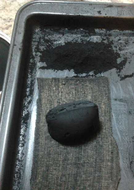
I finally located some charcoal I had lying around from
the last time I used the Hibachi (about 2002?), and found (to my
surprise) that unlike the powder, it wasn't an insulator, reading a few
megohms. That seemed promising... or was it just damp from lying on the
garage floor? I put it on top of an electric heater overnight. It was
quite warm. Instead of rising to infinity, the resistance had dropped
to around 1 MΩ. I put some in the oven at 350°F for an hour.
Test Electrode
I made another posode using pretty much the same
ingredient mix as
last month except charcoal powder instead of graphite powder, but also
with a 40 x 120mm piece of graphite felt folded twice
instead of three separate 40 x 40mm pieces. That way there would be no
breaks in the connectivity of the felt. That leaves only the break
between
the felt and the graphite foil current collector plate. In addition to
the osmium doping of the collector, I might try putting on a layer of
calcium hydroxide, which might also raise the oxygen overvoltage, and
which I seem to keep forgetting to add. It was about 2.4mm thick and
weighed 9.0 grams.
This month's mix was:
Monel - 18
Ni(OH)2 - 18
KMnO4 - 32 (subtotal 68)
Charcoal Powder - 12.5 (as "carbon black")
Sm2O3 - 7
----
87.5
g
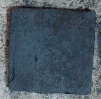 The electrode with charcoal powder (looking
much like most any electrode)
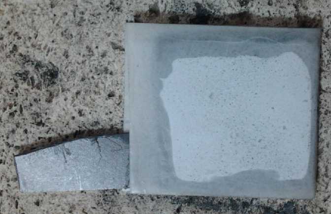
This time I simply wrapped the paper around the bottom and then waxed
the edges.
The melted wax did a lot of blotting into the paper, obstructing part
of the active surface.
It seemed to be reasonably but not totally effective at holding the
electrode substances contained - an improvement, but not perfection.
I had wanted to use 20 grams of charcoal, but it was
almost weightless - the 12.5 grams seemed to have as much volume as the
rest of the electrode if not more, even including the fluffy nickel
hydroxide. And I had to sand up most of a charcoal briquette to get it.
(notwithstanding that they weigh about 22g each.) It was very tedious
work and I hoped it wouldn't work well, so I wouldn't have to do it
again. Of course, one can create an automated sanding system for
production.
I didn't get the new electrode into the cell and get it
going until the 21st, and then it didn't seem to work very well. At
first when the charge was applied it jumped up to 3.5 volts with little
charge current being drawn. I used a larger resistor to bring it under
3. Then it 'drifted' down under 2 volts. This appeared to be a result
of improving conductivity as the cell charged.
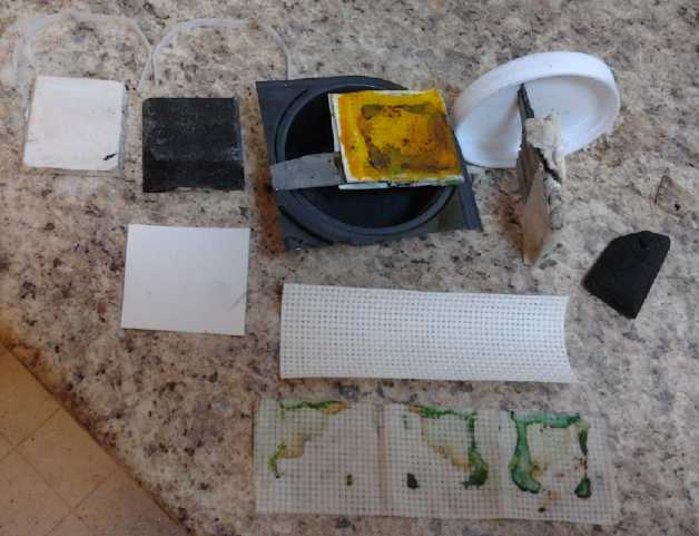 It did charge,
but after a day and more, on the morning of
the 23rd, it still had very high self discharge and low current drive.
This continued as long as I cared to keep trying to charge it, which
was until almost the end of the month. What had gone wrong? In the
meantime I took the cell apart and tried cleaning it, changing the
electrolyte, fixing it up, and while I was at it painting on/in some
ferric chloride - to no effect.
Someone on a list mentioned that charcoal has potassium
nitrate in it. This was verified on Wikipedia as one of a number of
ingredients that
may or may not be used in charcoal briquettes. Finally it sunk into my
brain that
the reason not to use polyamide as an electrode separator was because
it contained nitrates, which caused a "nitrAte-nitrIte shuttle" effect
that caused self discharge. It would seem then, that nitrate in the
charcoal was the culprit, and that I would have to find a purer source
of "carbon black".
In addition, there's no reason to suppose that the artist
supply graphite powder I've been using is really pure, either. If it
has traces of nitrates (or ??) in it, that would explain why my cells
have been having unacceptable levels of self discharge. In fact, this
seems like the most likely explanation. If I can solve the self
discharge, I'll have quite usable cells. I may try making an electrode
with no carbon powder at all, and see how effective the monel alone is
at making the electrode conductive.
Open Cell Graphitic Carbon Foam from Sugar
Someone sent me a link to videos of carbon and graphite
work done by some chemist interested in battery making. One that
particularly interested me was a way to make 'graphitic carbon foam'.
Whether this could replace the graphite felt is one question. Another
is whether this might be a pure form of what might be termed 'carbon
black' if sanded to powder - surely much more pure than charcoal
briquette. And this last might not require the final kiln heating step,
which would be difficult. I have a mini-kiln, but it's not temperature
controlled and a reducing atmosphere might be tricky to get, too.
https://www.youtube.com/watch?v=kflPZLGEKVc
Directions went something like this:
.5Kg sugar in frying pan
add .5 L boiling water
warm and dissolve sugar
add 8mL concentrated nitric acid, 2mL at a time
heat back on until it thickens up (initially stays clear, begins to
bubble, then golden brown, then deep brown and gets quite viscous.
(caramel) Done.)
Keep it hot or it sets rock hard.
pour into cake pan (teflon lined - sticks like mad)
bake for 4 - 8 hours - caramel foam - 48 hours @120°c it's carbon
foam. [carbon black?] Half open half closed cell. Back in at 235°
for 16 hours.
Put foam into stainless steel container. SS bowl on for lid
Kiln to 600°c in reducing atmosphere for 6-1/2 hours. Becomes
reticulated/open cell foam. Shrinks to 60% of its original size.
Catalytic Graphitization
------------------------
'transition metal' (Nickel or iron) catalyst
add bed of carbon to SS container.
http://www.TurquoiseEnergy.com
Victoria BC


 On the 17th I
thought again of the Mazda with its meager
range further reduced by having only 10 batteries, and also of the NiMH
D cells I had bought months ago to make up EV batteries and other
battery packs from, still sitting unused.

 I
soon noticed that although south-facing provides the
maximum daily solar collection (in the northern hemisphere), in the
early morning and in the evening the sun is up but essentially not
shining on the collectors. This leads to the thought that having some
collectors facing southeast and some southwest would in fact provide
more 'bang for the buck', and for a longer period of the day. Since
that's not possible with my roof slopes, I thought it might be nice to
have additional panels, some facing east and some facing west, to
extend morning and evening collection hours.
 The idea of
"carbon
black" instead of graphite powder sounded enticing, but getting hold of
some of a suitable nature might be tricky... unless perhaps it could be
made from some
common carbon substance such as charcoal. I wasn't sure how that might
work, but it occurred to me that methyl benzene (toluene) or tri methyl
benzene (an ingredient in "Diesel Kleen"), might dissolve the
"partly oxidized carbon" charcoal substance, and it might solidify in a
desirable conductive form when the liquid evaporated. Or, regardless,
it might convert to a desirable form on charge or discharge of the
electrode. Those aren't developments that I can predict, but any
performance improvement attained ought to be measurable, so it might be
worth a try to see what would happen.

 It did charge,
but after a day and more, on the morning of
the 23rd, it still had very high self discharge and low current drive.
This continued as long as I cared to keep trying to charge it, which
was until almost the end of the month. What had gone wrong? In the
meantime I took the cell apart and tried cleaning it, changing the
electrolyte, fixing it up, and while I was at it painting on/in some
ferric chloride - to no effect.