Turquoise
Energy Ltd. News #75
April 2014 (posted May 3rd)
Victoria BC
by Craig Carmichael
www.TurquoiseEnergy.com
= www.ElectricCaik.com
= www.ElectricHubcap.com
= www.ElectricWeel.com
Feature: Flat Panel LED Light:
simple, low parts cost, looks nice (see Month in Brief, Other Green
Projects)
Month In Brief
(Project Summaries)
In Passing
(Miscellaneous
topics, editorial comments & opinionated rants)
* Prep Brochures, finances, gardening, aquaponics, the Spark of God
Within
Electric Transport - Electric
Hubcap Motor Systems
* Centrifugal torque converter - new version 1/2 made
* Bedini style bicycle motor-generator?
* Lithium cells are heavy?
Other "Green"
Electric Equipment Projects
* Power Adapter Battery charging components printed circuit board
* Prototype flat panel LED light: promising design, simple, low parts
cost.
* Thermoelectric Fridge & heat pumping experiments continued.
* Bane of Peltier modules: nearly all are rated 15 V max: 22-28 V gives
much higher COP at 12 V.
Electricity Generating
* Flux concentration for magnet motors?
Electricity Storage - Turquoise
(NiMn) Battery Project etc.
* Need pure graphite powder
No Project Reports on:
Lambda Ray Collector, Magnet motor, Pulsejet steel
plate cutter, CNC Gardening/Farming Machine (sigh, maybe summer...
2014...
2015?),
Woodstove/Thermal Electricity Generator (may abandon),
evacuated tube heat radiators, individual EV
battery monitor (almost started on circuit board).
Newsletters Index/Highlights: http://www.TurquoiseEnergy.com/news/index.html
Construction Manuals and information:
- Electric Hubcap Family Motors - Turquoise Motor Controllers -
Ersatz 'powder coating' home process for
protecting/painting metal
- Preliminary Ni-Mn Battery Making book
Products Catalog:
- Electric Hubcap 4.6KW BLDC Pancake Motor Kit
- Electric
Caik
3KW BLDC Pancake Motor Kit
- NiMH Handy Battery Sticks, 12v battery trays & Dry
Cells (cheapest NiMH
prices in Victoria BC)
- LED Light Fixtures
(Will accept BITCOIN digital currency)
...all at: http://www.TurquoiseEnergy.com/
(orders: e-mail craig@saers.com)
April in Brief
I decided that April would
be well spent if I made a 2.4v Ni-Mn battery cell that worked half
decently without any notable self discharge, and made or at least
progressed well towards making a new version of the centrifugal torque
converter with a flywheel to give the "torque hits" the punch needed to
turn the drive drum instead of slow the driving motor.
I didn't get to the battery cell beyond thinking
about it. The first idea was to use no graphite or carbon powder at all
in the positive electrode, since impure powder (from an art supply
store) is now the suspect in the self discharge, and accept a high
impedance electrode. (The graphite felt and graphite foil, being made
for battery use, are probably pretty pure.)
Later I decided I should
look up some supply and see if I could order some graphite powder of
known purity, or else make some from the sugar technique. The big
trouble with that last was, where does one get nitric acid? No doubt
that
too would be a special order from somewhere, not a local pickup. Later
someone told me that you can make it from sulfuric acid (battery store)
or hydrochloric acid (hardware store), so I'll look that up when I get
there. Another potential for trouble is... the product is said to be
'pure', but might nitric acid not leave some nitrates behind? That's
the very thing that causes self discharge. Perhaps there's some other
way to make graphite. But it's all academic until I find time to dig
into it.
I started with the torque converter on the 4th, but didn't
get far except for a theory and a 10" x 5" aluminum ring purchase. The
theory went that many small slots would slow the motor less with each
hit and reduce or even eliminate the need for a flywheel. The other
part of this was that instead of having springs to hold the shoes back
until the speed was high enough to want to engage, springs would push
the shoes outwards against the drum at all times,
in order to shove the toes farther into the
slots than inertia would take them at any speed, and give torque hits
with enough force to move a car. It would have to be low enough spring
force
that the motor wouldn't jam with the toes in the slots when everything
was stopped.
Then the fridge started cooling poorly (a peltier module
had cracked - they're not well supported in my unit) and I diverted
into re-examining peltier modules and how to use them to best effect. I
re-examined using two stage cooling, but to cool by about 30° the
highest COP still seemed to be a single stage run at much lower than
its
maximum voltage.
Ironically the common 15 volt rated modules have
needlessly poor COP at their typical voltage of 12 volts and a typical
30°c spread from the warm side to the cold side. People seem stuck
on 'maximum pumped watts' and ignore the fact that they can do
approximately as much cooling by driving them at lower power, owing to
less internal heat being generated. It is especially surprising that
camping coolers, hungrily eating battery power, shouldn't be made to be
as efficient as possible. Modules rated for around 22 to 28 volts max,
which are hard to come by, work much better at 12 volts.
But I finally found some affordable "24 volt" peltiers,
along with some "4 volt" ones, (from China with no datasheets, sigh!)
and I placed an order. This was well. The cracked unit when reinstalled
seemed to be working nicely... for a few days, then it quit completely.
I put in a 6 amp module for the time being.
In the middle of the month, I started thinking about the
long overdue website that Jim Lawrence had created for me in 2011, but
which was never quite usable. When it was started I felt it was best to
let him do the rather complex coding, and anyway I didn't want to spend
my time on it. But owing to the fact that the new site was
theoretically being done, I stopped trying to update the old site, and
everything got more and more out of date. Now everything was a snapshot
of early 2011. After a last try to get him to do some updates which
didn't appeared on the site after a couple of weeks, I finally decided
I'd have to tackle it myself if it was ever to be made usable.
It was a beautiful page format, but the coding was so
complex that as I tried to change things, I soon had borders in the
wrong places, missing pictures, and all sorts of headaches. After a
second frustrating session of 3 hours, at 1 AM I put it up and linked
to it anyway. At least I reorganized the menus, edited some text, wrote
a little history of the development of the Electric Hubcap motor
system, and put in a couple of newer pictures... one of which refused
to show. The next day I got to the right hand column of the two column
page. The content is still woefully far from updated and presenting
things well, but at least it's on the move.
I'll be taking Jim up on his offer of "any help I need".
Getting back to the
torque converter, cutting the small, thin slots - easily done with a
bandsaw
- into the inside wall of the ring/drum looked like a challenge.
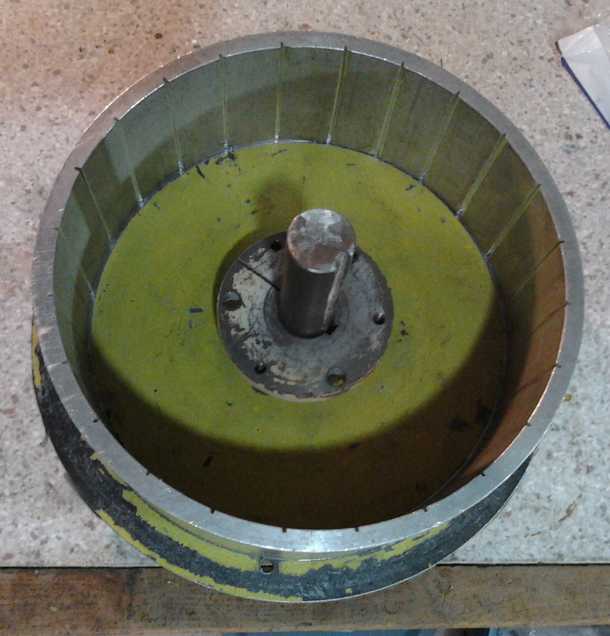
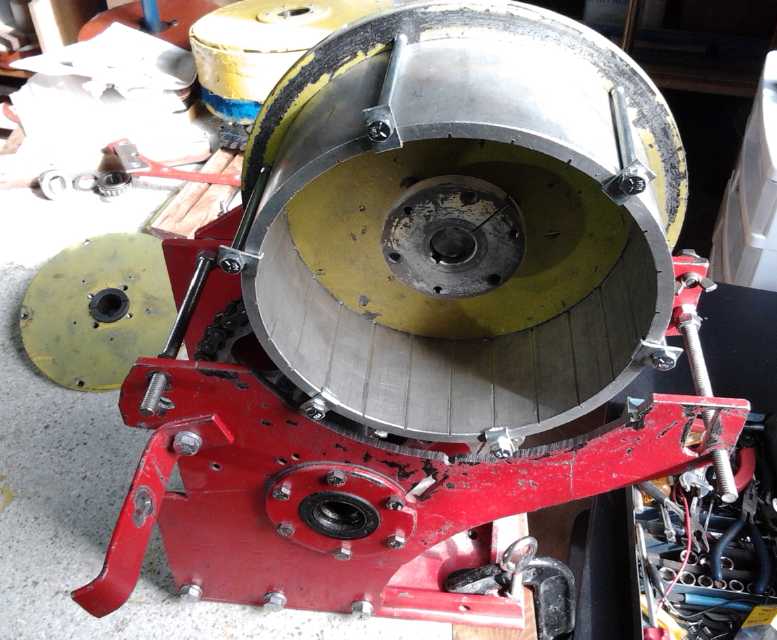 Centrifugal Torque Converter drum with narrow slots,
mounted in the Chev Sprint transmission box.
On the 17th I finally took an old, broken bandsaw blade
(the sharpest one to be found in the bushes where they get thrown) and
silver soldered it together looped through the 8" I.D. torque converter
'drum' ring, installed it on the saw, and cut 24 slots into the inside
wall. For once, it all went more smoothly and easily.
At first I thought I would try this smaller drum converter
on the
motorcycle and save the big one for the Sprint car. Since previously
the motorcycle would only just start moving at 60 or 70 amps with a 4:1
chain reduction, getting a decent ride from a torque converter, at much
lower amps, should at least prove the converter's efficacy.
Then I started thinking about the walls: round plates,
with pressed bearings in the middles, for both walls. The drum would
turn independently of the shaft that would go right through it and turn
the shoes rotor inside. A gear or pulley would attach somehow on one
side. On the other hand... it would be simpler to try it on the car
using
the same configuration as before. If it wasn't quite there with the
small drum, I could reconfigure it all and put it on the bike. If it
did really well, I could put in another gear and drop the final ratio
from 4 to 1 to 2 to 1, which should put it on the street RPM-wise, if
not on the highway.
I had to cut a big arc out of the side wall of the housing
since this drum was too wide to go inside, and I ended up taking the
motor apart to put a new and longer shaft in it. That was as far as I
got for April - but it's good progress.
Then, after a friend needed a battery charger adapted for
NiMH cells, I did 'generic' printed circuit boards to put between AC
power adapters or lead-acid battery chargers and NiMH (or other?)
batteries to adjust the voltage and limit the current to what the
adapter could handle. The component values will vary with the
application, but at least they can all be mounted on a decent board
instead of strung haphazardly on a wire. Not offering chargers has been
a sticky point for those interested in buying NiMH batteries. This
should simplify things.
After that PCB and toward the end of the month, I decided
to do the PCB for a flat panel LED light I'd been considering. Instead
of one or two large LED emitters, it has a dozen or more smaller ones
spaced around the board. Curiously, all of them together cost much less
than single large emitters, and there are no especially costly parts
except the 12 volt power adapter to allow 120 VAC operation. I made a
nice 13 watt prototype light to test. I hooked it to the 12 VDC solar
wiring. There are some things to change and improve such as to find a
diffuser that absorbs less light, but with its practical simplicity,
low parts cost and IMHO simple visual appeal, I see great product
potential - especially as electricity costs rise.
Some see more sales potential in getting specific colors
of LED emitters and making them as grow-lights. It's not what I had in
mind, but it might be pretty simple to offer both. Maybe I'll make a
few and try them in the aquaponics setup. Year round lettuce would be
great!
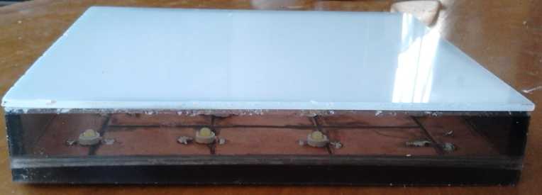
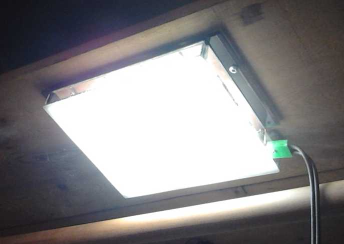 Flat-panel LED light, 1" x 6.5" x 7.5", 12 watts
In Passing
(Miscellaneous topics, editorial comments & opinionated rants)
Collapse warning pamphlets - finances - gardening and aquaponics
I spent one of the first days of April writing a single
page
'pamphlet', Are You Prepared
for the Coming Collapse?, warning of the apparently inevitable
financial collapse,
which will surely lead to a period
of global chaos and devastating supply disruptions. The media have kept
silent about this biggest story of our time, perhaps hoping to delay it
or avert panic. Who wants to hear it anyway? Few are old enough to
remember the disastrous disruptions of the first half of the 20th
century, and few will listen to an individual 'alarmist' or prepare,
but they'll all remember who warned them and many may come knocking on
the door when
there is no food supply and none to spare. So those who are prepared or
preparing are
afraid to try to warn others.
But the more who are prepared, the better for all.
Thinking on this problem, I got the idea to
distribute pamphlets anonymously, quietly dropping one or two here and
there around the neighborhood, and hoping some would reach people who
are listening. But somehow so far I've just put a few on park benches,
on one evening.
I've been burning through money with disquieting speed in
the last year. (Why haven't I finished filling out my SR & ED
investment tax credit forms yet?) Partly it's energy projects and some
overdue home maintenance, and partly it's inflation. Fuel, various
items of food, and even various materials and parts are up
substantially.
On the other hand, Turquoise Energy made a bit of money in
2013 - a pittance, but I trust the trend will continue and expand.
Someone is buying an Electric Weel 'kit' as a large, low RPM generator.
Another person (or two) is interested in an Electric Hubcap or Caik
motor and
controller for a boat. And since I think I have the answer to the last
NiMn battery chemie problem - self discharge - there's the possibility
of battery manufacturing agreements.
One of the other projects is expanding the vegetable
garden. I keep thinking of the CNC gardening/farming machine to make
gardening easier, but without finding a moment to work on it.
Then I saw some info about aquaponics and looked it up on
youtube. Basically the fish waste is pumped around and fertilizes the
plants, and the clean water goes back to the fish. It uses a few
plastic containers piped together for the fish (tilapia are popular but
need warm water) and vegetables, a water pump, and an aerator pump. It
can be done on any scale and seems like a very good way to get both
fish (protein!) and vegetables from a small area, with the inputs
apparently consisting of fish food, vegetable seeds, and much less
water than for a regular garden.
Spark of God Within
Sometime around 200,000 years ago, a brilliant spirit
being, administrator of several hundred evolving worlds, Lucifer, and
his assistant Satan, decided to run things their way and to heck with
the rest of the universe, preaching a doctrine of unbridled personal
liberty. This caught the imagination of the spiritual overseers of
about 3 dozen inhabited worlds - especially very primitive worlds like
Earth was back then. After a very, very long while as we humans would
view it and every opportunity to make their case to all, the rebels
were incarcerated and replaced, but the 3 dozen planets have pursued
stormy courses. 37,000 years ago Earth's rebel overseer, Calagastia,
tricked the new physical representatives of higher order into trying a
proscribed act - to speed up the painfully slow planetary progress by
trying to produce a great leader for one of the more advanced tribes.
(You guessed it: Eve had sex with an Earth native. Cain wasn't Adam's
son.)
Since then, we've been virtually disconnected at the
humanly conscious level from all association with higher beings except
for two brief periods. This planet has become so materialistic the very
idea of there being some sort of spiritual oversight guiding our paths
and planetary progress is thought by many to be silly, and the entire
vital issue is little discussed and perhaps little considered.
But the Lucifer Rebellion was, at long last, evidently
adjudicated in or about 1986 Earth time. Only the rebels' way of
thinking has been left behind. I wrote quite a while back how our
civilization appears to have hit an evolutionary dead end, how the
entrenched have seized power, and have politically and economically
disenfranchised the inventive and those who would bring progress; how
society thus can't make the self corrections and changes that need to
happen to continue evolving towards a bright future.
The turmoil now starting to make itself felt in many lands
is the beginning of a wrenching and rather rapid evolutionary
adjustment back towards the normal paths of love, life and light. This
program planned on high will gradually result in the changes in
attitudes and perspective of most individuals that will make humanity
receptive to major changes in social systems and structures. Future
generations will be contemptuous of 20th century civilization, and the
social order won't settle down for a long age of moral quickening and
progress.
The program will culminate, perhaps long after all now
living have moved on, in the adult physical appearance of a magisterial
son, Serara, a spiritual relative of Michael of Nebadon (AKA Christ
Michael). He may perhaps stay for some human generations, suggesting
ideals of social and political organization - as leaven in the bread to
foster human progress.
It would seem that one of the key things if not the one
key thing, that the celestials presently in communication via various
volunteer contact persons and associated e-mail lists would have us
understand, and which far too many are unaware of, is that every person
of normal mind has within his or her mind a spirit fragment derived
from the first source and center of all things, the uncaused cause, God
the Father. By faith one can come to know and experience
that this is true - through prayer and meditation, seeking, receiving
and following the guidance of the still, small voice that ever says
"This is the way!" This is the doing of the Father's will, which leads
us to do better and to gradually become more divine, even to be all we
can be.
Electric
Hubcap Motor Systems - Electric Transport
Centrifugal Torque Converter
In considering the previous torque converter attempt,
with 5 very large
torque hits per rotation, the motor was greatly slowed with each hit.
This meant transference of much of the impact force to the motor, the
transmission housing, and the body of the car instead of to the output
drum. Again, it was like driving a spike with a tack hammer. The remedy
to smooth out the force would be a fairly substantial flywheel on the
motor shaft. With that, the shaft would probably have started turning
instead of
just the car shaking. I considered buying a new identical steel brake
drum and
making 10 smaller slots in the wall for somewhat smaller hits twice as
often, and adding a flywheel, just to prove the point. This seemed like
a lot of effort and again there was just nowhere a heavy flywheel could
be conveniently added, just for a test.
I then considered the clutch - centrifugal or otherwise -
where the torque of the motor is evenly applied, turning the output
shaft... and making heat. No flywheel is needed owing to the steady,
even forces.
If there were enough very small slots in the drum, there
would be many small torque hits, and the weight of the motor rotor and
the shoe rotor driving the drum could be sufficient flywheel weight for
them.
Even if no single hit was sufficient to move the vehicle, the rapid
succession of lighter hits might do it, just like the 'infinitely'
rapid succession of very minute hits in a clutch.
A 'new' thought for the torque converter was that the 10"
I.D.
x 4.5" aluminum pan drum could mount on a car wheel, making the
originally planned Electric Hubcap configuration, perhaps more easily
than the
Sprint transmission mounting could be modified. But that would mean
that the converter would have to move the car with no following down
gearing. But I hadn't been successful yet even with a 4 to 1
reduction following - why build in an extra challenge?
Another idea that occurred to me was that with the smaller
8" I.D. x 3" pipe, I could try making a converter for the motorbike
first, and then
apply any lessons learned before hacking up the larger one. Since
previously the motorcycle barely started moving at 60 or 70 amps with a
4:1 chain reduction, getting a decent ride from a torque converter, at
much lower amps, would surely at least show the converter's efficacy.
 The E-Hog, a locally (Victoria BC
Canada) converted motorcycle, has a considerable
The E-Hog, a locally (Victoria BC
Canada) converted motorcycle, has a considerable
motor and a 4.125:1 reduction with a huge rear sprocket gear. The fixed
ratio works
well once the bike is moving at street speeds, but in common with my
attempts it has
rather low torque from
a stop, making for slower take-offs. It's a fine bike as built,
yet it's another illustration of the desirability of creating a really
effective variable
torque converter to handle all speeds optimally.
I marked off the inside of the drum with 24 even lines
about an inch apart. This convenient number would mean 24 torque hits
per rotation, and the strength of the hits could be varied not only by
the size and shape of the slots and shoes, but by the number of shoes,
which could be evenly distributed if there were 2, 3, 4,
6, or 8. (There wouldn't be room for 12 or 24.)
On the 17th I finally took an old, broken bandsaw blade
(the sharpest one to be found in the bushes where they were thrown) and
silver soldered it together looped through the 8" I.D. torque converter
'drum' ring. I installed it on the saw and cut the slots in the inside
wall. Then I unsoldered the band to free the drum. For once, all went
smoothly and easily and I wondered - except for having too many things
to do - why I hadn't done it 10 days before.
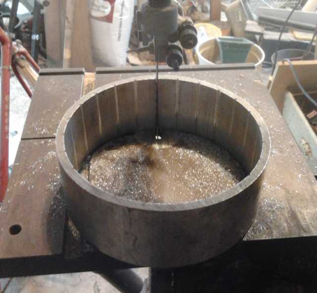 Cutting the slots/slits in the drum.
This was unusual not only for having to put the band together inside
the drum,
but for having to work from behind the saw to observe the cutting.
I had the idea to put a long shaft on the motor, long
enough to run through the converter, with the center disk with shoes
attached to it, and the grooved drum and output sprocket or pulley on
bearings to turn independently but perfectly centered on the shaft.
Then I started thinking about the drum walls: round plates, with
pressed bearings in the middles? The gear or pulley would attach on one
side. It would have to have side clearance and shaft clearance and yet
be perfectly centered. It would almost need a bearing on the outer
end...
As I thought about
disassembling the motor and the considerable reworkings and remountings
to make this, I decided to try this smaller drum in the
Sprint car after all, with the same basic configurations as before.
Faster to do. If it
didn't quite 'have it' in the Sprint, I could try the other route and
redo it for the bike.
 On the 24th I
had my plans, but I decided to run them by
the people at AGO. Well, nix on welding steel to aluminum! (I should
have known - the two metals have completely different melting
temperatures.) But for an drum end, I had
happened to pick a used 10" rotor disk with six threaded mounting holes
(from the first centrifugal converter). These turned out to be exactly
outside of the drum diameter (wow, what luck!), and so could be used
with long bolts and hooks to clamp the cylinder to the disk. (I used
some small angle brackets, with one leg partly cut off, as hooks.) The
machinist from AGO came over after work and we figured out a simple way
to mount
the rotor - any rotor with an SDS taper lock shaft bushing center - for
turning on the lathe, where I dug a groove into one face to hold the
cylinder
centered. I didn't however turn it down to the size of the drum per the
original plan. That would have turned off the mounting bolt holes. (The
10" rotor had about 1/16" clearance over the lathe bed - whew!)
On the 24th I
had my plans, but I decided to run them by
the people at AGO. Well, nix on welding steel to aluminum! (I should
have known - the two metals have completely different melting
temperatures.) But for an drum end, I had
happened to pick a used 10" rotor disk with six threaded mounting holes
(from the first centrifugal converter). These turned out to be exactly
outside of the drum diameter (wow, what luck!), and so could be used
with long bolts and hooks to clamp the cylinder to the disk. (I used
some small angle brackets, with one leg partly cut off, as hooks.) The
machinist from AGO came over after work and we figured out a simple way
to mount
the rotor - any rotor with an SDS taper lock shaft bushing center - for
turning on the lathe, where I dug a groove into one face to hold the
cylinder
centered. I didn't however turn it down to the size of the drum per the
original plan. That would have turned off the mounting bolt holes. (The
10" rotor had about 1/16" clearance over the lathe bed - whew!)
Next, the motor and transmission mounting box was too
narrow to accommodate the 3" wide drum. I cut out a 10.2" diameter arc
from one side for the drum (or even a 10" drum) to protrude through. It
was well I cut it larger since I hadn't thought about the clamping
bolts sticking out beyond the 8.75" diameter.
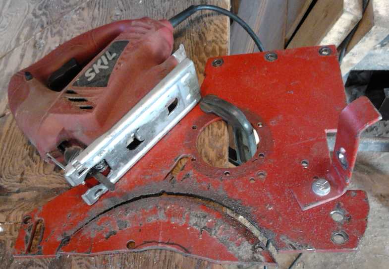 To cut this
1/4" steel plate, I used a jigsaw with a metal
blade, at quite a slow speed and pausing frequently to add more oil to
keep the blade cool. It took a while, but I made a rather clean 10"
long cut, with one (new) blade. The angle grinder with zip disks would
surely have cut it faster, but I'd have spent more time afterward
cleaning up the ugly inside-curved edge with a grinder. And it would
have still been rough. Cutting a whole 7.5" Electric Caik motor rotor
would be a 23.6" cut - tedious but doable with the jigsaw in a pinch,
if you don't want
to wait for waterjet people to get around to it or it's not available.
The 10" Electric Hubcap rotors are 5/16" thick and a 31.4"
circumference cut -
probably doable too, but would probably try anyone's patience and might
consume several blades. But I digress.
To cut this
1/4" steel plate, I used a jigsaw with a metal
blade, at quite a slow speed and pausing frequently to add more oil to
keep the blade cool. It took a while, but I made a rather clean 10"
long cut, with one (new) blade. The angle grinder with zip disks would
surely have cut it faster, but I'd have spent more time afterward
cleaning up the ugly inside-curved edge with a grinder. And it would
have still been rough. Cutting a whole 7.5" Electric Caik motor rotor
would be a 23.6" cut - tedious but doable with the jigsaw in a pinch,
if you don't want
to wait for waterjet people to get around to it or it's not available.
The 10" Electric Hubcap rotors are 5/16" thick and a 31.4"
circumference cut -
probably doable too, but would probably try anyone's patience and might
consume several blades. But I digress.
I didn't find a 1-1/16" center "H" coupling, and I finally
gave up and took the motor apart to change the shaft to a 1.0" one. (I
did learn about "boring bars" for lathes, and found there's a taper
lock bushing size smaller and seemingly better than "H", labeled "JA".
I may employ this size in the cramped quarters of the next Electric
Caik motor.) I made it a very long motor shaft, not only to reach to
the drum shaft through a wider drum, but also so a flywheel could be
mounted on the other side of the motor if one should be required. Then
I got onto other things and that was as far as I got, with the inner
rotor and some chunks of plastic for the shoes lying on the bench.
I plan to drill holes in the end of the motor shaft and
the drum shaft, and insert a pin between them to force them into
alignment.
"Bedini" style
bicycle motor?
With most 3-phase permanent magnet motor systems, the
magnets are in a balanced configuration, two poles, north and south,
for every three coils. In the 1970s John Bedini made a motor with
unbalanced
magnets, and he actually extracted electric power from it, charging a
battery, even as it ran a mechanical load. It's said Bedini was beaten
and threatened ("You'll use oil for the rest of your life or else!")
and subsequently did little work, but with his coaching his system was
demonstrated in the 1990s by a girl at a school science fair (the
"Bedini
SG"), confounding everyone.
I haven't investigated this in detail, but as I understand
it, the process goes something like this: Two like magnet poles are
used at opposite sides of the motor, instead of one north and one south
pole, and two coils. The iron coils and magnets are naturally attracted
to each other, and being unbalanced, there is a half of the rotation
that powers itself as the magnets approach the coils and they pull
together. Furthermore, during this part of the cycle, the coils can be
connected to an electrical load and generate power into it.
When the coils pass the magnets, electricity is applied
for a short period to make the repulsion to push them apart and
continue the rotation. Sometime before the midpoint is reached, the
coils are switched back to 'generate'. The energy stored in the
magnetic field from the powered phase is released to the generator as
the field collapses. This is where energy used turning the motor is
returned. After that it's back in the regular attracting, 'generate'
part of the cycle. The mechanical work done is less than the electrical
input applied, and the electricity generated is also less, but
evidently
together they add up to more than the electrical input. It
probably depends how hard the motor is working, but even under heavy
load it's likely to consume less power than a typical motor system,
owing to there being at least some returned electricity.
I still have the bicycle wheel rim motor in my mind, and
it has a lot of freedom of potential design at this point. Furthermore,
since the bike can be started by peddling, having torque at all points
of rotation isn't a strict requirement. Of course, a bike motor that
uses less electricity or even keeps itself charged would be fantastic.
I'm also not entirely convinced that the results can't be
achieved with
a regular permanent magnet BLDC motor, using a special motor controller
and perhaps two
separate
wires to each phase - neither delta nor wye wired. The Electric Hubcap
and Caik certainly have positions they magnetically pull themselves
into - "cogging" as it's called. By hand it's hard to turn the shaft to
break it out of these positions.
I intend to study
this further and then play with motor and controller design ideas for a
while before actually building anything.
Lithium Ion
Batteries are Heavy?
When I got the eleven 'Thundersky' lithium-ion cells home
(36v, 100 AH, 3600 WH) I weighed them as they seemed quite heavy. The
bathroom scale said about 93 pounds. When I disassembled them, one cell
read 3684g. For all the hype about the high energy density of this
chemistry, that's just 89 watt-hours/Kg, not 140-170 per the usual
published Li-ion figures. And I would mount them in some kind of box,
so they'd work out to around 80. Probably the heavy plastic cases to
protect such large cells accounts for much of the 'extra' mass, but it
shows that the 60-66 WH/Kg I get for NiMH D cell assemblies is
certainly not "eclipsed" by fabulously lighter weight with lithiums.
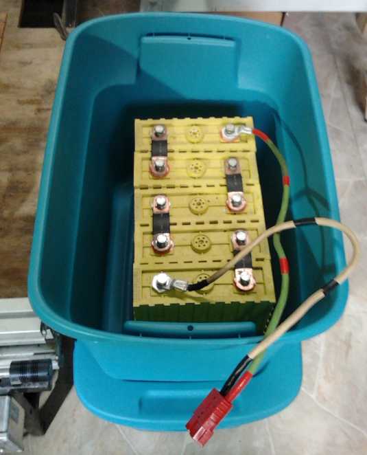 There were 11
cells total. To get "18 volt" batteries I
could use 5 and be perhaps a little low in voltage (16-19 empty-full)
or 6 and be rather high. With 5, I'd get two sets with a cell left
over, so that was the obvious choice. For boating, one set running low
would indicate it's high time to turn around and head home using the
other set. I got two tote boxes to put them in for in the boat, which
measured slightly too small. Sure enough, slipping a battery into one
it cracked in one corner, so I ended up with a totes considerably
larger than required.
There were 11
cells total. To get "18 volt" batteries I
could use 5 and be perhaps a little low in voltage (16-19 empty-full)
or 6 and be rather high. With 5, I'd get two sets with a cell left
over, so that was the obvious choice. For boating, one set running low
would indicate it's high time to turn around and head home using the
other set. I got two tote boxes to put them in for in the boat, which
measured slightly too small. Sure enough, slipping a battery into one
it cracked in one corner, so I ended up with a totes considerably
larger than required.
The left over cell could go into the Mazda as a token
lithium cell to bring it up to a nominal 135 volts. The Mazda would
then have all three typical battery chemistries: PbPb, NiMH and Li-ion.
3-1/2
volts won't add much to the performance, but it should allow for some
comparison between types... and add a challenge to making and
programming the individual battery monitor.
With a voltmeter, I noted that the cells weren't at equal
voltage. Two were substantially lower than the other nine (2.4+v versus
2.7+ for the rest). When I connected a set directly to a 90w solar
panel
four were soon over 4 volts while the fifth was still down at 3.6.
Evidently a charge controller/Battery management
system is important even for a few Li-ion cells in series. Hmmf! I got
an 18.5 volt, 3.8 amp power adapter as a charger, and some 3.9 volt
zener diodes at the local electronics store to put across the cells to
prevent excess voltage. But they're only 2 watts and would probably
burn out with the solar panel and charged batteries.
Electric
Mazda/Lead-Acid Batteries/Mixed Batteries Update:
battery watering, constant voltage float charging, pulse charging
At the electric car show in February, Canadian Electric
Vehicles showed a Mite-E-Truck dump truck with a lead-acid battery
watering system installed. I've heard of these, but they seemed a bit
of a luxury
item to me. On the 13th it occurred to me that I hadn't checked the
water levels in the Mazda batteries in a long time.
Presently the Mazda has two 90 AH NiMh batteries composed
of 90 D cells in tubes, one 100 AH NiMH battery as a soldered pack of
100 D cells (two stacked wooden boxes of 50AH), 5 'regular' deep-cycle
lead-acid batteries with two
pop-off triple cell covers, two sealed lead-acids, and one lead-acid
with six screw-off cell caps.
Nothing could be done with the NiMH dry cells and the
sealed lead-acids even if it was desirable, leaving six.
I had never opened the one with screw-off covers. The
cells all looked as dry as a bone. Perhaps it's supposed to be that
way,
but I added 100mL of water to each cell to get the level just over the
plates, which bubbled air as I filled. (It worked well afterward.)
The five 'regulars' were still full to the max after all
these months. Obviously a battery watering system here would be a waste
of time. This seems like a vindication of sorts for my gentle 'constant
voltage' (13.8 to 14.0 volts) float charging system. After an initial
fill, watering is virtually a non issue.
However, the glowing reports of the retention of
performance and longer life span afforded by "pulse charging" (or
perhaps "supersonic charging"?) at last led me to buy a
pulse charger. It's a pretty slow charger that reduces the pulse
strength as the battery charges, and it seems to me it would do as well
(for lead-acids only) as my
float units, and keep them in optimal condition. The only trouble with
making them the regular PbPb chargers is that each one costs more than
100$ - substantially more than a "reconditioned" battery. I rotate it
around every couple of days to occasionally "pulse" each of the several
PbPb s in the car.
That didn't stop the one battery that was in the car since
the beginning, for a year, from losing mileage rapidly over a few days,
in spite of pulse charging it. (...bought in 2009 or 2010 and it had
sodium sulfate added when new. It sat around a lot until I got the
Mazda.) I removed it on the 24th and the car was down to 120 volts
again. I
caught on fairly soon and I don't think I ruined it with over-discharge
like I probably did to some others (must do that individual battery
monitor!), and I intend to try renewing it.
I found all the tire pressures were down a little, 25 to
32 pounds, and I filled them to "max", 35 PSI. Following this, and also
with warmer weather, the amp-hours needed to go a mile went from
2.2-2.5 down to as low as 2.0, in spite of being short a battery. Wow!
Other Green
Electric Equipment Projects
PC Boards to make AC Power Adapters
into Battery Chargers
When I speak of nickel metal hydride batteries, people ask
about charging. I usually say I just charge them with a constant
voltage float charge, but they seem to want more detail, like a
specific charger and a price.
The simplest way is to use a power adapter, generally
followed by a diode or two to isolate it if there's no power and or to
reduce the voltage to a desired figure, and a resistor to limit the
current when the battery is low, followed by the battery. If the driver
is a "real" battery charger being adapted for a slightly lower voltage,
usually from PbPb to charge NiMH instead, it may need a sense resistor
bypassing the diode in order that the charger senses the presence of
the battery. Various component values are necessary for different
setups. A fuse might be a useful addition.
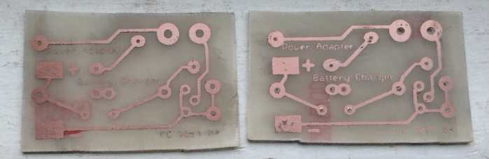 Finally it
occurred to me to make "generic" circuit
boards that can accommodate the common arrangements. Most power
adapters have 'typical' jacks on them, so using the matching socket
means no modifications to the adapter; just plug it into the board. For
the battery end, I just used big solder pads to attach any cable. On
the board are spaces for a fuse, one or two 5 watt resistors or one 10
watter, one or two large diodes, and a sense resistor across the diodes.
Finally it
occurred to me to make "generic" circuit
boards that can accommodate the common arrangements. Most power
adapters have 'typical' jacks on them, so using the matching socket
means no modifications to the adapter; just plug it into the board. For
the battery end, I just used big solder pads to attach any cable. On
the board are spaces for a fuse, one or two 5 watt resistors or one 10
watter, one or two large diodes, and a sense resistor across the diodes.
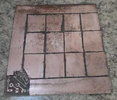
I designed boards on the 26th, printed a sheet with 12,
and etched 3. The patterns were large, but there was some pretty fine
text in the copper, which came out more legible on one board than on
the other two and showed the limits of resolution of the iron-on system.
I found a couple of layout problems and I did a second
board design on the 27th, but haven't made any so far.
Now, for example, to charge my 18v lithium batteries, I
have an 18.5 volt, 3.8 amp power adapter. If one plugged any such
typical adapter straight into any appropriate batteries when they were
low, it would be overloaded.
I'll omit the diode on this one since the voltage is just
right as it is. No sense resistor is needed. Since the cells may go
down to about 16 volts: 18.5v-16v=2.5v. A .66 ohm resistor would thus
limit the current to 3.8 amps when the cells are 'fully' drained. So
I'll append on this one's circuit board just the power adapter socket,
a .68 ohm*, 10 watt resistor or perhaps two of .33 ohm*, 5 watt, which
I may have on hand, and a fuse. The solder pads will connect a cable
with the battery's charging plug on the end.
* For the uninitiated, the reason seemingly odd
resistor values are commonplace is that each one is 20% higher
resistance than the last starting with one: 1.0, 1.2, 1.5, 1.8,
2.2, 2.7, 3.3, 3.9, 4.7, 5.6, 6.8, 8.2, 10, 12, 15, ... and as
electronics manufacturing got better there came to be 10%, 5% and even
1% values in between.
Making a
Prototype LED Flat Panel Light
After I had done the first
PCBs for battery charging on the 26th, I decided I should tackle my
conception of a flat panel LED light using a number of small emitters
apparently to be run at 1 watt: 2.9V, .3A, and 90 lumens. If it had 4
sets of 4 LED emitters in series (theoretically 11.6 volts), it should
work at 12-15 volts, draw a
little over an amp, and put out 1440 lumens. Using a bunch of small
emitters is actually substantially cheaper than using a couple of big
ones - they come in packages of 20 for about 5$, versus using two big
ones for around 10$ each. And they're more amenable to PC board
mounting, since the heat is spread out among the emitters and across
the board area.
Note: One 'failure mode'
drawback of my circuit is that the current is constant, so if one LED
in one of
the 4 legs fails, that leg will go dark, but the other 3 legs will
be driven too hard and will brighten - until they too burn out. Well,
best not to drive them hard enough that any will fail.
I simply divided the main area of the board into 16
rectangles, one per emitter, each forming a big slab of copper
insulated
from all the other slabs by a small gap. This would do the maximum of
heat sinking without adding components. Since my budget version of
Eagle PCB layout wouldn't do a big board, I copied my latest LED driver
board into one corner, and did the big blocks in a paint program.
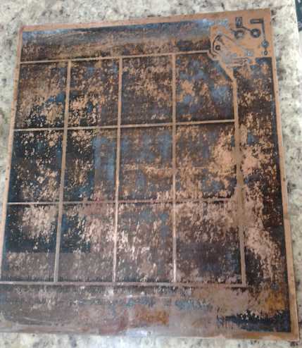 Of course I
couldn't very well do a foot square board with
the laser printer. 7.5" x 10" would have been about the printer's
limit. I picked 6" x 7". When I printed it on the glossy paper, I could
see that interiors of big squares don't have much toner. (It wasn't too
noticable on regular paper.) This translated into blotchy or missing
areas in the artwork when ironed on to the PCB. This is the first board
on which the iron-on transfer method hasn't worked well since I
learned not to rub the iron back and forth but to lift and move it, and
to be really careful to press near the edge of the iron down on each
and every point of the surface... but then I did start rubbing it too,
owing to the large board size. I used packaging tape to cover the
rectangles up for etching. That was a lot of work to do an obviously
hand-made job. Production will probably need
another method. Or perhaps non-solid line pattern squares can made --
which may print out better?
Of course I
couldn't very well do a foot square board with
the laser printer. 7.5" x 10" would have been about the printer's
limit. I picked 6" x 7". When I printed it on the glossy paper, I could
see that interiors of big squares don't have much toner. (It wasn't too
noticable on regular paper.) This translated into blotchy or missing
areas in the artwork when ironed on to the PCB. This is the first board
on which the iron-on transfer method hasn't worked well since I
learned not to rub the iron back and forth but to lift and move it, and
to be really careful to press near the edge of the iron down on each
and every point of the surface... but then I did start rubbing it too,
owing to the large board size. I used packaging tape to cover the
rectangles up for etching. That was a lot of work to do an obviously
hand-made job. Production will probably need
another method. Or perhaps non-solid line pattern squares can made --
which may print out better?
Later it occurred to me I had another laser printer. It
might do better. And I hadn't even set my usual printer to "darkest" -
although its adjustment range is slight anyway. And then that it should
be a good board to do with a dremmel router on the CNC machine, because
most of the copper is retained and only strips need to be removed. I
must make a holder to mount the dremmel on the CNC machine!
 I etched the
board on the 28th - and I left it in too long and over-etched an
already shoddy looking piece of work. I soldered on the 16 LED emitters
and tried it out with the lab power supply. The brightness seemed good,
but it took about 13.5 volts to get full brightness, instead of 11.6.
Once again, it looked like "2.9 volt" LED s aren't necessarily 2.9
volts, or even close to it. Full current would take at least 14 volts
with the driver voltage losses. Evidently I could only put 3 in series
instead of 4, making a board with 12 emitters and 1080 lumens - or just
accept that it wouldn't be entirely full brightness except when the sun
was shining on the solar panels.
I etched the
board on the 28th - and I left it in too long and over-etched an
already shoddy looking piece of work. I soldered on the 16 LED emitters
and tried it out with the lab power supply. The brightness seemed good,
but it took about 13.5 volts to get full brightness, instead of 11.6.
Once again, it looked like "2.9 volt" LED s aren't necessarily 2.9
volts, or even close to it. Full current would take at least 14 volts
with the driver voltage losses. Evidently I could only put 3 in series
instead of 4, making a board with 12 emitters and 1080 lumens - or just
accept that it wouldn't be entirely full brightness except when the sun
was shining on the solar panels.
Then again, I thought, the 16 emitters might total 1080
lumens or more even when it wasn't full brightness, and each emitter
would be driven more gently. 900mA (225mA per leg) * 16 emitters, gives
a value of 14.4. The full 1200mA (300mA per leg) * 12 emitters = 14.4.
But the light value of the 16 is greater because the majority of the
brightness comes from the first half of the current - the second half
gives somewhat less. And emitters driven with 225mA will run cooler
than with 300mA. But when I tried it, it still took over 13 volts to
get 800mA. So much for that idea!
On the 29th I removed one LED from each string and put
wires across the gaps. As might be suspected, it now took about 10.5
volts to reach 1200mA (300mA per string). When the internal constant
current power supply was wired and tested, 12 volts was exactly the
lowest voltage that made full power. Power supply efficiency would be
10.5/12=87% at 12 volts and 75% at 14 volts. A good switching regulator
could do better than the linear for 14 volts, but at 13 or less there'd
be little point to it. If there's 14 volts it's because the system is
being charged (ie, for solar the sun is out), and a few extra percent
power to lights will hardly be noticed. I went back to the supplier
website (dx.com) and found more exact specs for the emitters, which I
hadn't discovered before. They still appear to underestimate the 3.5V
forward voltage drop, but even the "3.2V" figure says four won't work
well at 12 volts.
- Material: Plastic + copper
- With LED white light
- Power: 1W
- Voltage: DC 3.0V~3.2V
- Current: 300~350mA
- Brightness: 80~90LM
- Color temperature: 6300~6700K
- Contains 20 pieces a pack
I still thought maybe a
lower current in the emitters would be preferable. 5 strings of 3 LED s
instead of 4 strings, run at 250mA each instead of 300, would mean a
1250mA total supply instead of 1200, and 15 emitters emitting at this
somewhat lower current would probably be brighter than 12 at 'max'.
Also on the 29th I got a piece of 3/16" 'frosted' plexiglass. It was
actually pretty clear and probably let nearly all the light through,
but one could see the outline of each emitter as a bright spot. If it
was moved a couple of inches away, it was somewhat more acceptable.
Somehow that didn't quite fit my vision of a flat panel. But maybe a
"light box" would be a good adaptation.
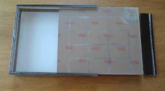 And herein
came an idea with a new advantage: The commercial flat panel lights all
had aluminum edges, and that had been my plan all along. But I could
glue acrylic edge pieces, any height, to the acrylic front, and skip
the metal entirely. These sides could be slotted to slide the circuit
board into, and I could glue acrylic tabs to the edges for screwing the
unit onto a ceiling or wall - a feature lacking in the aluminum edged
lights. Most of the whole unit would glow: light would come out the
sides as well as the face. The whole unit would be substantially
simplified, the materials costs would be low, and it would look nicer
and give a bit more light.
And herein
came an idea with a new advantage: The commercial flat panel lights all
had aluminum edges, and that had been my plan all along. But I could
glue acrylic edge pieces, any height, to the acrylic front, and skip
the metal entirely. These sides could be slotted to slide the circuit
board into, and I could glue acrylic tabs to the edges for screwing the
unit onto a ceiling or wall - a feature lacking in the aluminum edged
lights. Most of the whole unit would glow: light would come out the
sides as well as the face. The whole unit would be substantially
simplified, the materials costs would be low, and it would look nicer
and give a bit more light.
I cut the sides of the box in white on the radial arm saw,
but discovered the white scrap plastic I used wasn't acrylic - it
wouldn't bond to the frosted face with methylene chloride. or probably
with anything else. Rats!
 I visited the
plastic shop the next morning, the 30th. A translucent milky white
acrylic for all faces would be great. They only had 1/8" thickness of
that unless I had it specially cut, so I got that for the bottom and
some 1/4" thick "bronze" acrylic for the sides. I asked about the light
properties of the translucent acrylic, and found one more and a serious
inefficiency: the 1/8" was said to absorb 50% of the light, and the
1/4", 70%. (They didn't have 1/16".)
I visited the
plastic shop the next morning, the 30th. A translucent milky white
acrylic for all faces would be great. They only had 1/8" thickness of
that unless I had it specially cut, so I got that for the bottom and
some 1/4" thick "bronze" acrylic for the sides. I asked about the light
properties of the translucent acrylic, and found one more and a serious
inefficiency: the 1/8" was said to absorb 50% of the light, and the
1/4", 70%. (They didn't have 1/16".)
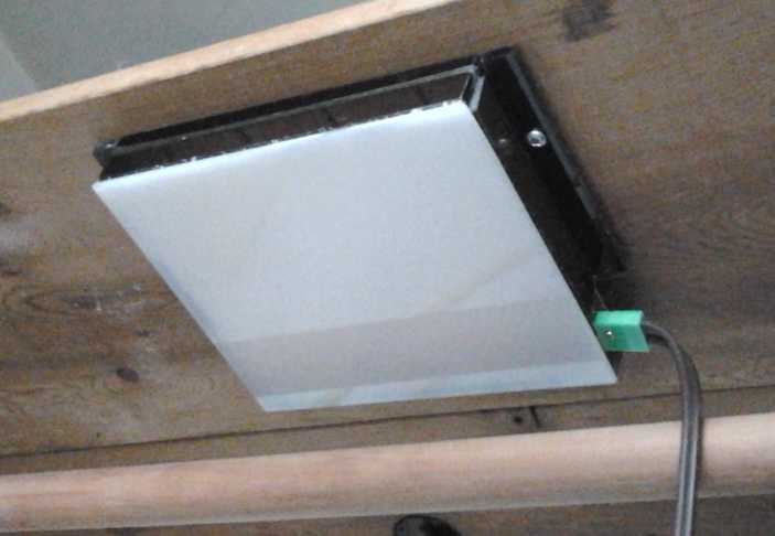 The flat panel LED light, mounted with a couple
of screws
The flat panel LED light, mounted with a couple
of screws
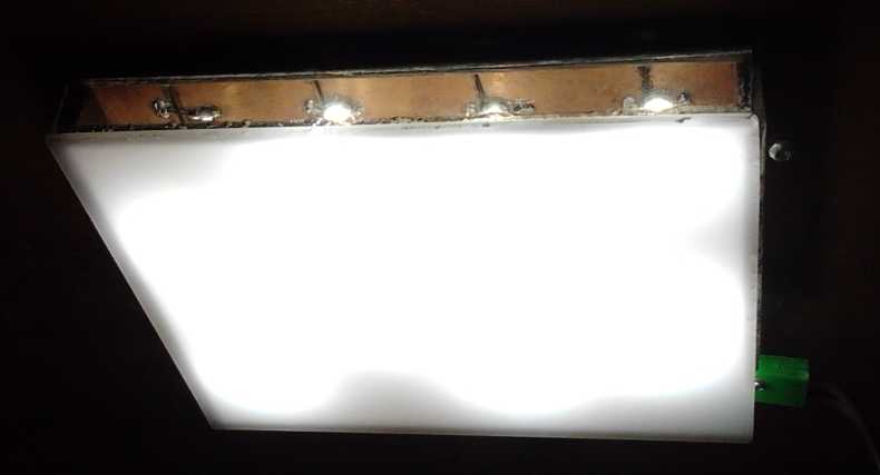 The "bronze"
turned out to look unexpectedly like "clear" with the bright LED s
inside, and they glare out from the sides. Then there's the ugly
circuit board with the missing LED emitters making for an uneven light
pattern. However, it's a prototype for a potentially excellent product,
which I will improve on for the next rendition... and a nice light
regardless, which I will use. I anticipate these will be both less
costly and more desirable than the LED globe lights have proven to be
so far - they're another new form interior lighting can take. But
rising electricity prices will make all LED lights more popular.
The "bronze"
turned out to look unexpectedly like "clear" with the bright LED s
inside, and they glare out from the sides. Then there's the ugly
circuit board with the missing LED emitters making for an uneven light
pattern. However, it's a prototype for a potentially excellent product,
which I will improve on for the next rendition... and a nice light
regardless, which I will use. I anticipate these will be both less
costly and more desirable than the LED globe lights have proven to be
so far - they're another new form interior lighting can take. But
rising electricity prices will make all LED lights more popular.
For testing and temperature readings I mounted it in the
solar PV system wiring closet where there was already a 12V CAT plug-in
and it was within easy reach. I'll be looking for a bottom cover
that'll
transmit more light without allowing the glare of each emitter to show
through.
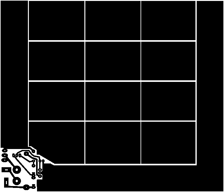 The prototype flat-panel LED light printed
circuit board layout
Thermoelectric Equipment - Experiments
The prototype flat-panel LED light printed
circuit board layout
Thermoelectric Equipment - Experiments
First, the Conclusions...
There's a mishmash of stuff below, essentially my 'lab
notes' written at the times I was doing the paper research and the
experiments. So here are the main findings, which most may not care to
read beyond.
1. I couldn't find 'nanomaterials' Peltier modules with improved COP s
for sale so far. There are a number of patents for them.
2. Laird has some 'improved'(?) peltiers rated for higher voltages for
sale at electronic suppliers (Digikey, Mouser) that may be a little
better than most - but they are costly. DX has some small (15x30mm), '4
volt', 5 amp Peltiers that can add their voltage to a 15 volt (5 amp)
unit to raise its voltage rating, as well as a '24 volt' 6 amp unit and
several '12 volt' units, for affordable prices. Since DX provides no
datasheets with any of these, use is somewhat speculative. Undoubtedly
the '12 volt' units are rated for 15 volts max. like all the others. Is
the
'24 volt' one really 30 volts? I ordered some anyway. They haven't
arrived yet.
3. Owing to heat rise on the module warm side and the need for the cold
side to be below freezing to freeze an ice tray, the temperature spread
is likely to be around at least 30°c with a 20° ambient room --
and higher if the Peltier module generates much extra heat owing to
excessive input power, or in warm summer weather.
4. To get a good coefficient of performance , Peltier modules should be
run at around 50-65% of their maximum rated voltage. For a 12-14 volt
system, modules rated for maybe 20-28 volts, or combinations of modules
to
attain these voltage ratings, use much less power (than typical 15v
max. units) to provide almost as many watts of cooling.
5. Most Peltier modules, and nearly all the lower cost ones, are rated
about 15 volts maximum, intended to pump maximum watts of heat with
12-14 volt systems. But this is an unfortunate choice for typical 12
volt
cooling and heat pumping. The extra power used by the lower COP shows
up as extra heat in the warm side, so except with noisy high rate fans
the temperature differential is
greater and it actually consumes those extra watts to pump the same
amount of cooling to the cold side. Typically it appears there's no
cooling gain at all over using a higher voltage module(s) at 12 volts
with lower
current (and hence consuming less power) to attain higher COP.
In my fridge, power used with a single 15V, 8.5A module
was about 85 watts, and the warm side temperatures were exceeding
40°c.
For a 15V, 6A module, using 60 watts, the warm side was about 35°
and the tray would only partly freeze over.
It has a quiet fan, but a very good heatsink. With two 8.5A modules
(15v+8v) making a 23V rating, power was 45 watts, the warm side was
just 30°, and the ice tray froze as fast or faster as with the 85
watts.
6. Thus 15 volt units - almost the only ones available - don't take
into account the need to conserve power in battery operated systems,
energy conservation and efficiency in general, nor the extra heat that
will raise the temperature of the warm side. Of course, they could be
run at 7-9 volts quite effectively, but for 12 volt power that
introduces power supply issues. At 6 volts of 15, the cooling capacity
gets rather low with a typical temperature spread, so using two
peltiers in
series doesn't appear to work out very well at 12 volts either.
7. Peltier modules pump heat more efficiently across a low temperature
differential, so I thought a two-stage unit with one Peltier on top of
another, each pumping across 15° instead of 30°, might give a
better COP.
The problem is that the warm side module has to dissipate
the heat made internally by the cold side one as well as the heat
pumped by it. So far, for a 30° spread, it looks like things work
out pretty much the same with either single or two stage cooling.
However, this is not the last word. I've ordered more
modules to get more balanced pumping between the stages and try more
actual experiments. Sometimes there are things that don't show up in
the datasheets - for example, when the unit is shut off, less cold will
be transferred from the fridge to the warm side heatsink through two
layers than through one and so it'll stay cold longer.
8. A technique recommended to maximize thermal conductivity is to
metalize the warm side of the peltier module and solder it to the
heatsink. Since graphite seems to conduct heat very well, an experiment
I'm trying is to mix silicone heatsink grease and graphite
powder, to get a much better thermal grease. Ideal contact with the
heatsinks could lower the temperature differential at the peltier
surfaces by a couple of degrees - and maybe double that for two stage
coolers. It seems to be working well, but spreading it thinly and
evenly is still vital - the difference is probably small.
Thermoelectric Fridge Update: another
cracked peltier module
I got on the web to see if perhaps anyone had started making
higher performance peltier modules, and I read that they have a life
span of some sort, with deteriorating performance over time. This was
the first inkling I'd had of that, which
would mean occasional module replacements would have to be figured into
the cost of peltier driven appliances. At the same time seemingly just
to emphasize the point, the fridge started working worse and worse, and
after a couple of days, it would no longer even make ice, just cold
water. (The copper bar right under the modules remained iced over.)
I had been thinking I might change it from 15+8 volt
peltier modules to 15+4 volt ones to get faster freezing of the tray,
but I had only 15v and one more 8v matching modules. I thought of
trying 8+8 (was that really better than 15?), and I took it apart on
the 8th. But a corner of the 8v peltier was cracked. That was of
course the reason it wasn't working well. I thought I had again clamped
them too tightly, but on
further reflection, they don't seem to deteriorate immediately, and
pressing on a corner of the heatsink would stress out the edges and
corners of the peltiers even if they were clamped loosely, potentially
breaking them. It would seem I need to ensure that external stresses
don't couple through to the modules, or they'll continue to get
'randomly' broken.
The choices were to use 15v+8v [the other 8v], 15v+15v, or
a single 15v.
IIRC 15+15 didn't make enough cooling, and the large surfaces caused
excessive transfer of cold to the heat sink when the unit was
off. I put it together as it was, 15+8 with the spare 8, and considered
getting more
options (8v, 4v, 2v) next time I ordered electronic parts. It turned
out after some perplexing experimental results, when I finally read the
numbers on the part, that the "spare 8V" unit was in fact a 12v unit
with the same smaller dimensions as the 8v one. I didn't have a spare 8
volter.
I haven't found any nano layered materials, higher COP
modules - so far. No doubt the lifespan of uncracked peltier modules is
at least several years -- and surely much longer if used at around
1/2 the maximum ratings instead of up near the limit.
The Two-Stage Peltier Cooling Module Revisited
In reading I was reminded that efficiency of Peltier
modules increases rapidly with decreasing temperature differences. (The
piece suggested that they might be used in conjunction with compressor
and gas heat pumping to increase the efficiency.) I had early on
concluded that using two stages instead of one didn't make much
difference... but had I discovered the 'deceit' of the graphs when I
estimated that? And might the result also be improved by the efficiency
increase gained by running the modules at well under maximum
voltage? It seemed to deserve another look.
(The document said:
http://www.thefreelibrary.com/Thermoelectric+technology+assessment%3a+application+to+air+conditioning...-a0186399835
CONCLUSION
Some observations on thermoelectric technology, especially those
relevant to large scale air conditioning and refrigeration.
* Thermoelectric modules are solid-state electronic devices that
directly convert electricity to temperature difference. Thermoelectric
devices have no moving parts and therefore are inherently reliable and
require little maintenance. Furthermore, the lack of refrigerants used
in the systems provides many benefits to the environment as well as for
packaging and safety.
* The use of thermoelectric devices and systems has been limited by
their relatively low energy conversion efficiency. Present commercially
available thermoelectric devices operate at about 10% of Carnot
efficiency if used as home refrigerators, whereas compressor-based
refrigerators usually operate at about 30% of Carnot efficiency.
* A broad search for thermoelectric materials with high efficiency has
been conducted. Currently, there is no known theoretical impediment to
significant increases in thermoelectric energy conversion efficiency. A
breakthrough in thermoelectric materials could spark many applications
that use thermoelectric technology as a safe, efficient, and reliable
alternative.
* Thermoelectric technology is suitable for applications where its
compact size, reliability, absence of moving parts, and silent
operation outweigh its relatively low efficiency. Thermoelectric
devices have been used in situations where the heat load is small
(e.g., <25 W), the required temperature lift is small (e.g.,
<10°C [18°F]), or the variation of the heat load is large
(e.g., train passenger cabin). It is important to note that the COP of
thermoelectric modules increases significantly with decreasing
temperature lift, as shown in Figure 4. [figure wasn't there]
* Instead of utilizing a fully designed thermoelectric cooling system,
it is also possible to use a small thermoelectric system as a subcooler
to improve the performance of a traditional system. This is a "hybrid
system" since it combines a solid-state cooling device together with a
conventional vapor-compression-type air conditioning and refrigeration.)
Now, if one took the 30° spread for the fridge or a
heat pump, and divided it into two 15° stages, being run
(especially the second stage) in the peak efficiency area per voltage
and current, could a higher COP be obtained even with today's 'low
performance' modules? If a COP of 2 could be obtained, a warm side
peltier delivering twice the cooling could sit directly on top of the
cold side one running 1/2 the power (assuming they were the same size
or separated by a block of copper to fully contact both surfaces),
and the temperature drops should be about equal.
I dug into the CUI module datasheet graphs. Again the
graphs were deceptive and difficult to evaluate, since they chart watts
of heat transfer versus temperature for different supply currents
instead of for different supply watts. 1/2 current (all else
being equal) also means 1/2 voltage and hence 1/4 power, not 1/2 power.
I finally printed out a couple of the graphs and started scribbling
numbers on them.
My estimate, which can only be a rough one, was that four
15V modules could be used to attain better COP. Two "8.5A" modules
(40mm square), electrically in series and hence being run by 6 volts
each, would sit on top of two "4A" or "5A" modules (same dimensions,
same wiring) and at 12 volts deliver around 40W of cooling power. Total
supply current would be 5.8 amps, for a 70 watts supply draw. (At 13 or
14 volts, all the figures would rise a little. I didn't work it out.) A
single 8.5A peltier would use about 80 watts to make about 35 watts of
cooling. So the improvement seems to be there: more cooling with less
power. And
there might be somewhat less heat leakage from the cold to the warm
side when the unit is off.
The fridge at present probably has only about 25 to 35
watts of cooling, but it would be nice to up that so it can cool faster
while the sun is out, so 40 watts would be better. Otherwise, the
peltiers could be reduced to say 6A and 4A devices, or 5A and 3A.
Is it worth it? Maybe. Certainly for a heat pump in a
battery powered electric car, all savings in power are valuable.
Logically the next thing to try figuring out was how two
sets of three stacked peltiers, each dropping 10° to make the 30,
would fare. A quick look showed that with the small change in
temperature drop, the 6 modules would use more electricity than 4 and
pump less heat. If the temperature drop was, say 45°, three stages
might become worthwhile.
Being lazy, I stuck an 8.5A and a 6A peltier together,
connected them in series, and tried them out. The voltage balance
looked
reasonable and I installed them in the fridge. I got the following
rough readings:
Supply: 12.25 v
8.5A peltier: 5.20 v
6.0A peltier: 7.05 v
Current: 2.7A (33W in)
Or (unplugging the electric car so the voltage came back up):
Supply: 13.7v
8.5A (warm side) peltier 5.9v
6.0A (cold side) peltier 7.8
Current: 3.0A (41W in)
Next question was how much cooling would that provide? If
it made 20 watts of cooling it would be doing well, and that probably
wouldn't be enough. After a few hours the copper bar had frost, but it
took ages to make ice in the tray, and the coolest area in the fridge
was about 7°.
The next morning, the 9th, I tried wiring the two stacked
modules in parallel instead of in series. With 12.4v in it drew 9.5
amps - 120 watts, and probably making about 30 to 40 watts of cooling
to the fridge. That's a pretty poor coefficient of performance and at
best no more cooling than the theoretical two pairs at half voltage
using 70 watts. Furthermore, it's probably an overestimate, because
with so much power going in, the heatsink temperature rose from the
usual 27-33° to a high measure of 46°, negating the
intended lower temperature difference effect. In fact, it made so
little cooling the ice melted off the copper bar.
It's frustrating that nearly all common (cheap) peltier
modules are rated
~15 volts maximum. This would be of course to get maximum cooling from
a 12 to 14 volt battery supply. However, a much better COP from those
voltages is attained from peltiers rated about 20 to 24 volts.
These seem to be considered specialty products and cost far more. A DC
to DC converter might take the voltage down to 7, 8 or 9, but that
introduces its own inefficiencies and complexity. That
leaves putting two modules in series, which at 12 volts leaves them
running at just 2/5 of their rated voltage, where performance is
marginal for a 30° temperature spread. 1/2 to 3/5 is probably ideal.
In the afternoon I put in the "full deal", two stacks of 2
peltier modules, 8.5A and 6A. (I'd have gone for 8.5A and 4A or 5A, but
I only had one, 5A size.) Current was 5.1 amps, about 67 watts. After
temperatures stabilized, they read 37° - 25° - 0° (warm
side, between peltiers, cold side). It seemed the extra watts had
mainly just raised the high side temperature, and the 6 amp units were
somewhat too large to go under the 8.5 amp ones. Owing to the unequal
temperature distribution it appeared there would be only around 26
watts of heat pumped from the fridge instead of 35-40. In mid afternoon
the water temperature in the ice tray was 5° at the top and 3 or
4° near the bottom. I left it to see how fast it would cool. In an
hour those were only down one degree. It did eventually make some ice,
but most of the tray stayed water and the fridge didn't get under
6°.
But again, really the main reason for low heat pumping,
regardless of COP, was probably using the modules at 43% of their rated
voltage with the 15 volt peltiers in series (6.5v each), with no
intermediate voltage modules available. Where were all the other
possibilities like 10v or 24v?
I also went to DigiKey to look at peltier modules. Here
(and then elsewhwere), I found Laird Technologies peltier
modules, which had more thermocouples for higher voltage ratings.
"The UltraTEC Series is a high
heat pumping density thermoelectric
module (TEM). The module is assembled with a large number of
semiconductor couples to achieve a higher heat pumping capacity
than standard single stage TEMs. This product line is available
in multiple configurations and is ideal for applications that
require higher cooling capacities with limited surface area.
Assembled with Bismuth Telluride semiconductor material and thermally
conductive Aluminum Oxide ceramics, the UltraTEC Series is designed
for higher current and larger heat-pumping applications."
"The ZT Series is a high performance thermoelectric module
(TEM). The module is assembled with premium Bismuth Telluride
semiconductor material that achieves a higher temperature
differential than standard single stage TEMs."
It seems to be vaguely implied in the bolded phrases that
these
are somehow more than single stage peltier devices, but there is no
such indication in the datasheets. Three higher voltage modules looked
appropriate, which
would according to my readings of the graphs provide the following
results with 13
volts and 30° temperature spread (presumably with hot side
temperature 25°c) :
UltraTEC Series UT6,24,F1,5555 ("30V"): Supply 2.4A (31W), 28W pumped
[84-89$]
UltraTEC Series UT8,24,F1,5555
("30V"): Supply 3.4A (44W), 37W pumped
[108-$]
UltraTEC Series UT6,19,F1,4040 ("24V"):
Supply 3.0A (39W), 31W pumped
[66-71$]
ZT Series ZT5,16,F1,4040 ("20V"): Supply 3.2A (42W), 28W pumped [57-$]
ZT Series ZT7,16,F1,4040 ("20V"): Supply 4.1A (53W), 35W pumped [79-$]
[Prices Canadian$ @ Mouser-Digikey, April 2014]
The first three provide almost as much
cooling watts as input watts, and the 24V unit is also very good. This
is excellent for a 30° temperature spread - compare it to the 8.5A
Cui "regular" peltier type:
Cui CP85440 ("15V"): Supply 6.8A (88W), 37W pumped [24$]
But a comparison between 30v and 24v units at lower
voltage and a 15v unit isn't fair.
With a small 15° temperature spread, the specs were even more
impressive:
UltraTEC Series UT6,24,F1,5555 ("30V"): Supply 2.6A (34W), 51W pumped
UltraTEC Series UT8,24,F1,5555
("30V"): Supply 3.6A (47W), 70W pumped
UltraTEC Series UT6,19,F1,4040
("24V"): Supply 3.2A (42W), 52W pumped
ZT Series ZT5,16,F1,4040 ("20V"): Supply 3.3A (43W), 40W pumped
ZT Series ZT7,16,F1,4040 ("20V"):
Supply 4.4A (57W), 54W pumped
A worrisome feature of the
30 volt units, as with putting two 15 volt units in series, was that
they would be operating at the very bottom of their voltage range for
the temperature spread. If in the summer the 30° spread increased
to 40°, the heat pumping would be cut in half, and also by 1/3 if
the supply dropped just a volt to 12. The 24 volt unit wouldn't change
so drastically, going from around 30 to 20 watts at the 40° spread,
or to 25 at 12 volts.
The prices were steep, even as much as putting together
the four 'ordinary'
peltier modules, but the design appeared to do exactly what I was
trying to do, and better, in a single module. And the prices for all
the modules
were up sharply from the last time I ordered, a year or two ago.
Then I went to figuring out how my 'original' two side by
side peltier setup stacked up. The 15v and 8v modules in series
(electrically) made effectively a 23v one, about 50x50mm. According to
the graphs, it should do around 35 watts of heat pumping, with a supply
of around 45 to 50 watts. At a glance it looks as good as the fancy
setups except for one thing: it doubtless transfers substantially more
cold from the fridge to the outside heatsink when it's turned off.
Although two-stage pairs pumping across smaller temperatures pump more
heat, some of the heat pumped by the warm side unit simply goes into
counteracting the heat produced by the cool side unit. (Maybe if the
warm side dropped 20° and the cool side only 10? ...Then the cool
side would make less heat. But then the warm side would have to pump
that across the 20° instead of 15°. Maybe it all comes out
equal regardless of how it's configured?)
In order to keep the fridge cool I put in a 6 amp module
and awaited the arrival of the new choices. I'm still waiting.
This isn't the final word. I plan to try out more configurations and
two stage arrangements. There may be other details that
affect performance that, like the off-state heat transfer, don't show
up in the datasheets.
Electricity (Energy) Production
Magnet Motors:
Magnetic Shielding and flux concentration
It occurs to me that
in considering magnetic shielding, one should examine ceramic "cup
magnets". The rather thick-ish steel cups concentrate the flux around
the edge of the front face of the magnet, and in that limited area, the
field attains the force range usually associated with supermagnets. If
such cups were applied to supermagnets, the flux should be powerful
indeed.
If a magnet motor is going to work, this would be the
means of making it powerful enough to produce a decent amount of power
for its size, rather than feeble power that merely keeps it turning
itself with a small load or none at all. The way the cups are formed
for ceramic cup magnets is thus probably the ideal way to make them for
supermagnets and magnet motors. (Short lengths of steel tube with an
end soldered or welded on might be a simple way to go?)
Electricity Storage
Turquoise Battery Project
Ferric Chloride
I've mentioned painting ferric chloride onto/into the
positive electrode a couple of times. What's it for? It converts to
ferric oxide/hydroxide, and people have mentioned using this as a
positive electrode active substance. I thought I'd add it on spec.
But as someone on a list mentioned, it has another action.
In becoming oxide, it turns
copper into copper chloride - it's usual use is as copper etchant for
making printed circuit boards. This means it eats away at the copper
content of the monel, creating pits and rough surface area and exposing
more nickel on the surface where it can convert to chemically active
NiOOH and nickel manganates, both increasing the electrode capacity
derived
from the monel.
Finally, Cu++ of the resulting copper chloride is the ion
used in the electrolyte of an experimental battery which apparently
recharges the cell
from the ambient
temperature of the room. If such an action can be obtained, it would be
phenomenal. So far, the high self discharge of the cells has prevented
any such action from being observable even if it is present.
Cell with no Graphite Powder?
In order to test whether the graphite powder is the
culprit in the self discharge as suspected, I at first decided to make
a posode
with no graphite, and accept whatever higher internal impedance it
would
have. I didn't get around to it and now I think I'd best find some pure
graphite for a new electrode.
http://www.TurquoiseEnergy.com
Victoria BC