Turquoise
Energy Ltd. News #76
May 2014 (posted June 7th)
Victoria BC
by Craig Carmichael
www.TurquoiseEnergy.com
= www.ElectricCaik.com
= www.ElectricHubcap.com
= www.ElectricWeel.com
Feature: Plan for
complete torque converter transmission (see month in
brief, Electric Transport)
Month In Brief
(Project Summaries)
In Passing
(Miscellaneous
topics, editorial comments & opinionated rants)
* Hundreds of thousands of unsold gas cars fill hundreds of fields all
over the world
* OMG: Nuclear War? USA considers a nuclear missile first strike?
EVERYONE WILL
LOSE! NO MORE WAR!
Electric Transport - Electric
Hubcap Motor Systems
* "Centrifugal Torque Converter" is only a "Centrifugal Clutch"?
* A Bigger Plan: "CVT" transmission with planetary gear torque
converter and
centrifugal clutch
* Magnetic clutch torque converter: a new concept?
* Mushroom outboard: Leg from PP-epoxy composite?
* Individual Battery Monitor
* Mazda RX7 EV news: 18 V, 100 AH, 5 lithium-ion cells
* New concept in aluminum-air cells (can't recharge): install them in
vehicle for when regular range runs out
* Caik Motor: Ready-made Rotors
Other "Green"
Electric Equipment Projects
* Peltier Module Refrigeration
* Flat Panel LED Lights & Plant Grow Lights
Electricity Generating (no reports)
Electricity Storage - Turquoise
(NiMn) Battery Project etc.
* Carbon Black (or graphite) from old dry cells (sigh!)
* Lithium Ion 100 AH Battery Sets
No Project Reports on:
Lambda Ray Collector, Magnet motor, Pulsejet steel
plate cutter (dropping this one until and unless further notice), CNC
Gardening/Farming Machine (sigh, maybe summer...
2014...
2015?),
Woodstove/Thermal Electricity Generator (may abandon),
evacuated tube heat radiators.
Newsletters Index/Highlights: http://www.TurquoiseEnergy.com/news/index.html
Construction Manuals and information:
- Electric Hubcap Family Motors - Turquoise Motor Controllers -
Ersatz 'powder coating' home process for
protecting/painting metal
- Preliminary Ni-Mn Battery Making book
Products Catalog:
- Electric Hubcap 4.6KW BLDC Pancake Motor Kit
- Electric
Caik
3KW BLDC Pancake Motor Kit
- NiMH Handy Battery Sticks, 12v battery trays & Dry
Cells (cheapest NiMH
prices in Victoria BC)
- LED Light Fixtures
(Will accept BITCOIN digital currency)
...all at: http://www.TurquoiseEnergy.com/
(orders: e-mail craig@saers.com)
May in Brief
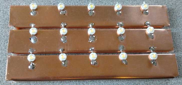
LED emitters soldered to copper sheets - good heat dissipation.
I became rather
enthused by the flat panel LED light design and spent some more days on
it, mostly finding supplies and sources and ordering parts. Since the
prototype alreay worked, I knew it was doable. It seemed
like something relatively simple to make with inexpensive parts, an
advance in ceiling lighting, not available in stores around here, and
hence
that might actually sell well, with the simple appeal of its low
profile, inobtrusive design, and probably at a better price than most
things I've been able to offer for sale so far. And plant growing
lights, which are mostly fairly costly, could be made in the same
design. I got the blue and red LED emitters for these along with the
whites.
When I found a thinner translucent acrylic plastic for the
bottom diffuser, I made a new case for the same prototype circuit
board. It let notably more light through. Then I abandoned the large
circuit board in favor of strips of thin copper sheet, which would
dissipate heat better, and only part of one strip would be the PCB.
With this system I can make lights about 4" wide and any length from 4"
to maybe 10", with 2 or 3 to maybe 8 or 9 series sets of three LED s
for
different brightness needs. Beyond 10" or so, the copper strips might
be a little flimsy. A thicker gauge copper could extend the length even
longer, but at a higher cost, and the current at 12 volts would head
over 2 amps.
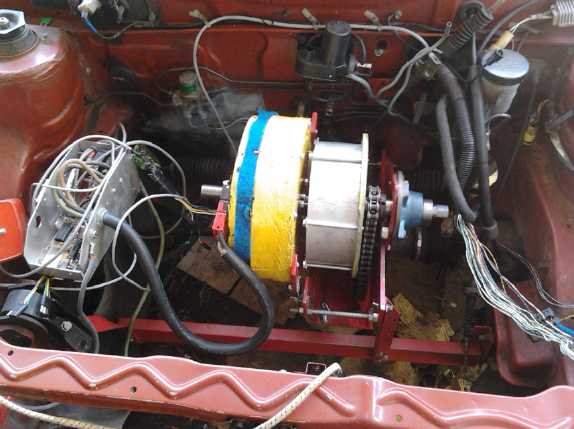
 At the same
time I picked away at the 1/2 finished centrifugal torque
converter, shaping new shafts for the drum and for the motor, which
would butt together with a pin to hold them in line with each other.
Then I made 8 plastic (UHMW-PE) pivoting shoes and mounted them on 4
threaded rods threaded through the input rotor in pairs, one on each
side of the input disk rotor in each position.
At the same
time I picked away at the 1/2 finished centrifugal torque
converter, shaping new shafts for the drum and for the motor, which
would butt together with a pin to hold them in line with each other.
Then I made 8 plastic (UHMW-PE) pivoting shoes and mounted them on 4
threaded rods threaded through the input rotor in pairs, one on each
side of the input disk rotor in each position.
On the 21st I tried it
out on the bench. In the forward direction there wasn't much torque.
Going backward there was considerably more but it didn't seem like
enough. But once again I had neglected to provide for a
means of measuring the torque on the bench.
Then I turned the motor up quite fast, and lost my grip
on the drum. I soon found I could hold it from turning at high speeds,
but just
barely. In all this, the motor didn't seem to be working too hard.
Evidently it wasn't being loaded down enough.
There were 4
pairs of shoes, and room on the rotor to mount 8 pairs, which should
presumably
double the torque and motor loading. In addition if necessary I could
add weights to the shoes, or springs, which
should make them push harder on the drum. The results seemed promising,
and if the car would only move one direction, that would
be good enough for now. First I made a new
drum/output shaft that could hold the torque wrench, and measure the
present levels of pressure... which turned out to be only 5
foot-pounds. That needed to be multiplied by about 20 to put the Sprint
car on the road.
I went with adding weights to the shoes - 3/8" x 2.5"
bolts. I put in larger (5/16") 'axles' for the now heavier shoes, and
actually reduced the number to 3 pairs, 120° apart. The heft of the
shoes now seemed more in keeping with the sizes and forces of other
car-motive components.
Bench testing commenced on the 31st. But I couldn't get
more torque out than the motor had, and early in June I became
convinced that my theory wasn't working and that I had only created an
improved(?) centrifugal clutch. But if that clutch was combined with a
planetary gear torque converter (PGTC) it would be a working system. I
already know the PGTC works once it's turning, but it needs a clutch to
allow it to turn before the car is moving.
Around mid month I put the MnO2 plus carbon black
substance from a dry cell in a jar, and rinsed it with 3 fills of
filtered water
to dilute out the NH4Cl electrolyte, then dried it a few days. Then I
was too busy to get back to it - Rats!
But I wanted to move ahead with the torque converter too,
and there seemed to be no end of other things that needed doing. I
finally saw an accountant about my corporate tax filing, now over 2
months late, that I was having trouble figuring out. He said it was too
hard for him. But he gave me the name of another accountant - who was
on holidays. But I finally saw him and he got me started again by
getting me to call a number at Canada Revenue for statements about my
'payroll account'. (It took a whole day to get through on the phone. I
could have had this straightened out a couple of years ago if Canada
Revenue had an office in BC's capital, where one could talk to someone
when confused.)
On the 30th I was informed that the U-Vic Ecosat
satellite, with the diamagnetics & laser navigation experiments, in
which Jim Harington of AGO Environmental Electronics has played the
leading role, was a go for funding to be launched. Until that day this
was still under consideration and nothing was certain.
My role in the project, at least so far, has been trivial
yet apparently crucial. In looking up some diamagnetics info on
Wikipedia, I passed on a link to a Japanese researcher mentioned in in
an article's references. It looked to me like his work was closely
related. He was contacted and indeed he became involved in and
important to the project.
I'm fairly certain that magnetic drive is the key to
practical travel across the solar system and between the stars. In the
more credible stories of UFO s, awesomely powerful magnetic fields
often seem to be a key feature, causing odd electrical phenomena, and
compasses to go wild. Room temperature superconductors have recently
been discovered here on earth. (For the first time ever, the
researchers had to raise the temperature, to 30°C IIRC, to find the
critical temperature.) If and when these are perfected, it will become
practical to produce such magnetic fields. But exactly how the drive
would work I'm very hazy on.
So as I write this newsletter the LED lights are 'in
process' for when I find time to do the new circuit board, I know in
principle how to do a working torque converter car transmission, and I
think (as I have for 2 months) that the NiMn batteries will work well
if I leave out the doubtless impure 'artist supply' graphite. It all
boils down to finding time to do these things along with other projects
(including aquaponics) and several aspects of arranging financial
affairs -- partly to plan ahead for possible financial and economic
collapse.
In Passing
(Miscellaneous topics, editorial comments & opinionated rants)
Where Unsold Cars Go To Die
 Someone sent me the link below
to an incredible article. It shows photo after photo of acre after acre
of brand new unsold cars, in various locations in various countries all
over the world. There are hundreds of thousands of them, if not
millions, just parked there and deteriorating. It also says there are
10 billion cars in the world - more than there are people.
Someone sent me the link below
to an incredible article. It shows photo after photo of acre after acre
of brand new unsold cars, in various locations in various countries all
over the world. There are hundreds of thousands of them, if not
millions, just parked there and deteriorating. It also says there are
10 billion cars in the world - more than there are people.
Evidently, everywhere cars continue to be produced as if there were
buyers, in
order to hide the lack of demand from the public. This in turn hides
the fact that
economies worldwide are imploding: Relatively few people can afford a
new car. As John F Kennedy said when I was young, "We all drink the
same water, we all breathe the same air." And today all our financial
and economic systems are, if not one, at least intricately linked. No
land is exempt from what's happening... and filling with unwanted cars.
I like to think that there are also
people waiting for electric or plug-in hybrid cars to improve and come
down in price,
who are putting off purchasing a new gas car just as they're
(hopefully)
becoming obsolete. I wonder how these vehicles would be selling if they
were
electric, with a similar or lower price tag than gas? (Ideally with
efficient variable torque converter transmissions, NiMn batteries, and
some sort of 'free energy' charging system.)
I anticipate it's likely that soon, if there's fuel to be
had,
it will
be pretty much unaffordable. The few electric cars on the road now will
become priceless.
Where
the
World's
Unsold
Cars
Go
To
Die
|
Zero
Hedge
Oh my God, the news Gets Worse!
Anyone for Thermonuclear War and Extinction of All Life?
The ongoing financial, economic and environmental turmoil
which must soon lead to a colossal crash is bad enough, but at the
start of June it developed that the Hypocrite in Chief and the
military-financial complex in Washington are talking about a first
strike nuclear attack on Russia and maybe China. Why? Simply because
they don't want any power to rise to challenge American hegemony over
the world. They believe like Nazis that they are "over-men" and all
others are "under-men", and they care not who or how many they kill to
maintain the hegemony and the illusion of "greatness" - a quality which
has been under
continual attack for a over century and which they have now completely
eradicated
from their institutions of national life. Hopefully nuclear war is only
talk and there is in fact some sanity to keep such ludicrous ideas in
check. But on the present administration, no bounds of reason can be
set.
On Greg Hunter's UsaWatchdog.com (can be found on
youtube), Dr. Paul Craig Roberts, a long connected and well informed
figure, says the hubris of the insane people in Washington is so great
they actually believe they can win it. Talk around governing circles is
"What good are
nuclear weapons if you can't use them?" They're building up an ABM
(Anti-ICBM) "missile shield" in eastern Europe. They are surrounding
Russia and China with these and other "military assets" in various
countries and bases. And the situation is all the more perilous
because, being widely known, it may tempt the target countries to
launch their own nuclear first strike before they are themselves hit.
But little has changed in the figures of "Mutual Assured
Destruction" ("MAD") since the 1960s.
Roberts reminds us of studies including a recent one that show that
if even 1% of Russia's and USA's nuclear arsenals are used, the death
toll will be in the billions, not millions. And if either side
lets off less than half its 'nukes', there will probably be no more
higher life on this
planet. Heavy strikes anywhere would unleash deadly radioactivity to
drift around the globe, and also cause a nuclear winter, with
daily temperatures in temperate zones below freezing for about
three years: there would be no food for anyone and most or all food
animals will also become extinct. He also says the
"missile shield" probably won't stop 5% of the return fire, but that
that's irrelevant for the above reasons. Everyone on all sides will
lose everything including their lives, and those responsible will be
found blameworthy before the judges of the Universe.
Here's a notice to anyone and everyone in control of our
affairs
everywhere that may chance to read these words: You have no more right
to lie, steal, defraud, cheat, extort, intimidate and murder than
anyone else. And especially:
NO
MORE WARS!
Electric
Hubcap Motor Systems - Electric Transport
Torque Converter: the Whole Transmission?
Centrifugal Torque Converter - or is it just a Centrifugal Clutch?
Let me start this by saying
that while my intent has been to create a centrifugal torque converter,
I've
never got more torque out than the motor itself had. At the start of
June, I tentatively concluded that what I may have made instead is just
a
new (... and hopefully improved?) design of centrifugal clutch. Unless
I have some further inspiration, I'll go back to the planetary gear
torque converter (PGTC) that
is known to propel the car, since it did so in September 2012 -- but
with this unit
as the clutch, the previously missing component to the PGTC
transmission. That would provide all the necessary pieces for a
complete transmission unit that is known in theory to work -- once I
redesign the housing, shafts & bearings et al again to fit
everything in.
So the drive train would be: the motor driving one of the
planetary's gears, the slipping gear of the planetary attached to the
tension rope & lever, the planetary's output gear driving the
centrifugal
clutch input disk rotor, the shoes hitting the clutch drum and driving
it around (with high torque from planetary gear converter), the chain
from that shaft driving the differential (car's original parts from
here), and the differential to the CV drive shafts driving both front
wheels. I'm not sure which element of the planetary gear will go where.
The centrifugal clutch might work best with a higher RPM than the motor
itself. Or, the slipping gear might somehow be combined with the
centrifugal clutch if I use the right combination, eliminating the
tensioning rope, manual lever and slip pulley.
 I
pecked
away lethargically
on the half done torque converter. On the 5th I drilled holes for
pivot pins for 4 pairs of shoes in the input rotor and cut and mounted
the first set.
I
pecked
away lethargically
on the half done torque converter. On the 5th I drilled holes for
pivot pins for 4 pairs of shoes in the input rotor and cut and mounted
the first set.
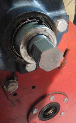
I decided to put a pin between the motor shaft and the
output shaft where they
butted up against each other to keep them turning in line. On the 11th
I
drilled a hole in the end
of drum shaft. The next day I bought a 3/8 x 1/2 x 1" bronze bushing.
On the 13th I threaded the shaft hole for a 3/8" bolt, screwed a bolt
in and cut off its top, leaving a smooth 3/8" concentric pin sticking
out.
Then I drilled a 1/2" hole in one end of the motor shaft
and
inserted the bushing. Theoretically the hole, drilled on the lathe,
should have lined up on center, but I could have done it better
freehand. I took the shaft to AGO and had it - the other end - done
there. AGO not only had a big enough lathe to simplify things, but
something I didn't know about called a 'center drill' (sets of them)...
and more know-how. "Of course your drill wandered off, because you
didn't square off the end of the shaft in the lathe first." That seemed
obvious once stated, but I don't remember it from my electronics
courses at
BCIT.
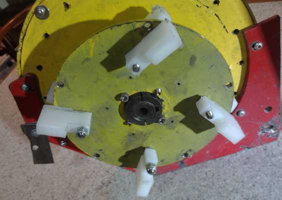
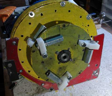
Then I made 6 more plastic (UHMW-PE) pivoting shoes and
mounted them: 4 sets on 4
threaded rods threaded through the input rotor in pairs, one on each
side of the input disk rotor in each position. I used no springs.
Finally I mounted the motor to fit it, took it off and
mounted the rotor disk on the shaft, and finally re-mounted it complete.
On the 21st I tried it
out on the bench. In the forward direction there wasn't much torque at
all.
Going backward there was considerably more but it didn't seem like
enough. (Actually I don't understand why it didn't just jam going
backwards. Later it did occasionally.) I had put the coupling pin in an
existing shaft I found for
the drum that was just right... except not long enough to grind a hex
shape on one end for attaching a torque wrench. Once again I had no
means of measuring the torque on the bench.
Then I turned the motor up quite fast. It didn't seem to
be working very hard.
Evidently it wasn't being loaded down enough. (And in the other
direction, even less.)
There were 4
pairs of shoes, and room to mount 8 pairs, which should presumably
double the torque and motor loading. In addition I could add weights to
the shoes, which
should make them push harder on the drum. The results seemed promising
enough to make more shoes and plan on
that basis - and if the car would only move one direction, that would
be good enough for now. But the first step would be to make a new
drum/output shaft that could hold the torque wrench, and measure the
present levels of pressure.
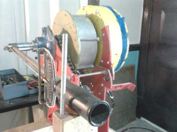
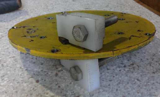
 Setup, with torque wrench to try to divine the
torque figures
Setup, with torque wrench to try to divine the
torque figures
I had that finished on the
24th, again with a bit of help
from AGO to drill the center hole. It turned out the torque was only
about 5 foot-pounds - about the same as the stalled motor. (This low
figure for stall was because I was running it off 18 volts for the
tests instead
of 36.) In the other direction the needle barely moved, maybe 2
foot-pounds.
Obviously the setup had problems. Doubling the number of
shoes to 8 and upping the voltage would still only produce maybe 12 to
15 foot-pounds. With the 4 to 1 reduction following, that might move
the car on level pavement, but it certainly wouldn't put it on the
road. But I was pretty sure the approach, a
disk rotor on the motor turning within a drum on the output side, with
slippery plastic bumping into things at specific points, had potential.
The size of the slots - or should they be protrusions? - and the
makeup of the plastic 'shoe' parts in between, remained wild variables.
 I decided to
try weights on the shoes. The light
plastic pieces would have much more impact with a hefty bolt bolted
through each one, oriented for the weight to centrifugally
push the plastic outward. While it was apart, I would smooth off the
edges of the slits in the drum to a 45° angle. (As usual the raw
aluminum edges were cutting the plastic.)
I decided to
try weights on the shoes. The light
plastic pieces would have much more impact with a hefty bolt bolted
through each one, oriented for the weight to centrifugally
push the plastic outward. While it was apart, I would smooth off the
edges of the slits in the drum to a 45° angle. (As usual the raw
aluminum edges were cutting the plastic.)
The four 1/4" threaded rods seemed too light for heavy
'boots',
so I cut holes for three 5/16" axles. I thus reduced the
number of shoes from four to three pairs, through which I put six 3/8"
x 2.5"
weight bolts. They now had a promising heft to them that seemed
much more in keeping with a vehicle transmission part. I finished two
on the 27th, then had two hectic days and got nothing more done.
 On the 30th I
dug out an old 'right angle blade' scraping tool I've had for
ages and scratched 45° bevels into tops of the slots to smooth the
edges. This gave
them a "Y" appearance. They were then much easier on the plastic.
Probably a 45° angle "V" would be the ideal slot shape.
On the 30th I
dug out an old 'right angle blade' scraping tool I've had for
ages and scratched 45° bevels into tops of the slots to smooth the
edges. This gave
them a "Y" appearance. They were then much easier on the plastic.
Probably a 45° angle "V" would be the ideal slot shape.
As I did it it occurred to me that where I was worried the
shoes would jam in one direction, I could simply shallow out the slope
on that side, ideally a shallow italic sort of "V" shape, worked
down until the shoes wouldn't catch on the shallowed slopes in that
direction. Then I made the 3rd set of shoes.
The next day, the 31st, I fired it up. In the weak
direction it now had about 5 foot-pounds. In the stronger it started
getting more. It was hard to read the dial on the torque wrench. It
vibrated back and forth, since the force was on-off pulsing - as
intended. It seemed to vibrate from about -20 to +30 foot-pounds. I had
the impression of double force or better - 10 or more foot-pounds, and
the motor was turning slower to get it. It was better loaded down and
didn't readily speed up. This time, with 24 pulses per revolution
instead of 5, the pulses were too rapid for the motor to change speed
much, so a flywheel would seem to be unnecessary. 10 foot-pounds still
wasn't enough to get the car moving. 15 or 20 probably would be on
smooth, level
ground, but it still wouldn't put it on the road. 100 would be ideal.
The peak
torque at the moment of impact of the shoes with the grooves was
probably higher than the average. Would the car see the peak force or
the average? - was it worth trying out on the car? I decided to try a
couple more
things on the bench first.
The first thing to try out was higher voltage. Half
voltage is only 1/4 power, and consequently the RPM wasn't getting all
that high. I had a 24 volt NiMH set up and I put it on to charge, then
connected it. (I've blown up too many motor controllers at 36 volts. I
need to improve them.) After trying it out and still watching the
needle bounce
all over, I decided to mount it on the car. Not surprisingly, the car
didn't move.
 The next idea
was more weight. I only had to remove the
motor to modify the shoes - the transmission box stayed in the car. The
weight bolts were
fairly long, and I got the idea to put coupling nuts on them. These
extended past the ends of the bolts and probably doubled the weight or
better. I remounted the motor. It didn't seem to work very well and I
had the impression the battery was low. I put on a 50 amp shunt and a
plug to plug in the voltage and current monitor. Sure enough, the
battery was very low, and I put a couple of 12V chargers on the two 12V
sides. But with the meter I could now see what was happening. 1/2 hour
later I went out and tried again, but the power was still dopping off.
According to the meter a lot more current was being used than I had
expected - up to about 80 amps, which dragged the battery voltage way
down. But
the 50 amp breaker didn't blow, neither did the two 30 amp (total 60
amps)
fuses.
The next idea
was more weight. I only had to remove the
motor to modify the shoes - the transmission box stayed in the car. The
weight bolts were
fairly long, and I got the idea to put coupling nuts on them. These
extended past the ends of the bolts and probably doubled the weight or
better. I remounted the motor. It didn't seem to work very well and I
had the impression the battery was low. I put on a 50 amp shunt and a
plug to plug in the voltage and current monitor. Sure enough, the
battery was very low, and I put a couple of 12V chargers on the two 12V
sides. But with the meter I could now see what was happening. 1/2 hour
later I went out and tried again, but the power was still dopping off.
According to the meter a lot more current was being used than I had
expected - up to about 80 amps, which dragged the battery voltage way
down. But
the 50 amp breaker didn't blow, neither did the two 30 amp (total 60
amps)
fuses.
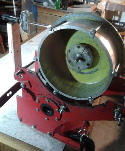
 Testing in the Sprint car
I had to conclude in multiple runnings that the car was
seeing the average torque, which was of course no higher than the
motor's torque. The 'torque pulses' were too brief and too small to
transfer through all the slack in all the linkages and the rubber tires
and start the car moving bit by bit, more with each pulse. At this
point, I've decided to again examine the planetary gear type of
converter, but combining this centrifugal clutch component with it as
the required clutch.
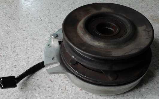
Electro-magnetic
Clutch
Torque Converter?: a new concept
On May 2nd someone thought I should look at a magnetic
clutch - a broken one from a lawn tractor was being replaced. We picked
up the old unit and I wondered how it might apply. Obviously a working
clutch is what the planetary gear converter was lacking, but I'm
presently trying to make the centrifugal converter, which doesn't need
a clutch. On the other hand, the centrifugal converter is similar to a
centrifugal clutch.
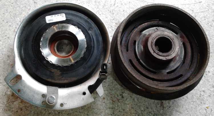 Electric clutch opened. The stationary
electromagnet (left side) is energized
Electric clutch opened. The stationary
electromagnet (left side) is energized
to spring the two clutch pieces (right) together and connect the input
to the output.
The electromagnet contrives to pull the two rotating
elements of the clutch together without itself having to spin, which
greatly
simplifies the wiring. The input has fittings for a one inch shaft such
as those I'm using. However, the output has a V-belt pulley and no
means for attaching a chain drive or engaging a shaft. The whole unit
is also
probably too small for a vehicle. But there may be larger units more
suitably configured.
The output has a springy mounting and is pulled slightly
sideways by the electromagnet to engage with the input. When not
engaged the input element rotates freely, but the output is pulled to
the other side, into contact with two non-rotating permanent magnets
that act as a brake. (It's a clutch for the cutting blades, so they
should stop rapidly when not wanted. For a vehicle motion clutch that
feature would be removed, or selectively engaged as a "Park" drive
lock.)
On the 4th it struck me that I had conceived various ideas
for things that would start a car moving, but wouldn't work because
they would "wind up" or engage, and there was no way to "unwind" or
disengage the system to create a repeating cycle, or else it would
randomly stop in the 'torque stroke' position, from which the car
couldn't start moving. But a magnetic clutch could engage and disengage
rapidly and repeatedly, resolving the impasse.
In fact, it can do much the same thing I'm trying to
accomplish with the centrifugal converter. Used as a pulsing element,
within mechanical limits the electric clutch can engage for any desired
length of time via its pulse width, as often as desired via its pulse
frequency. These times would probably be in terms of fractions of a
second, say 1/20th to 1/2. These two factors, pulse width and pulse
frequency, could be controlled more or less manually at least for
testing, or automatically by a microcontroller monitoring vehicle
speed, motor speed, and probably motor current. And there are other
parameters that could be adjusted, like putting in slots and patterns
like on the centrifugal converter, or using one plastic element to
smooth things and reduce noise. It might or might not need a flywheel
on the motor, depending on how the configuration and pulses work out.
It soon also struck me that this smaller clutch with the
V-belt
pulley, if repaired and used this way, looks potentially almost ideal
as a torque converter for the motorcycle. Perhaps I'll continue making
the centrifugal converter for the car, and try this hopefully pretty
simple idea for the bike. No shortage of projects!
After finding the centrifugal converter as made didn't
seem to be more than a clutch, my enthusiasm for this approach has
waned some. It might still be worth trying.
Mushroom Outboard Motor
It occurred to me one might make an electric outboard leg
out of two pieces of UHMW polyethylene, drilling and milling out the
spaces for the shafts, bearings and the double U-joint where the
direction changes for the prop. It seemed neat and tidy until I thought
about how to shape the outside to a streamlined teardrop profile.
Then I thought of carving a leg out of wood, making a mold
of it, and forming the leg out of polypropylene-epoxy composite. Light,
strong... But I have no plans for actually going ahead with this idea
at this time. No shortage of projects!
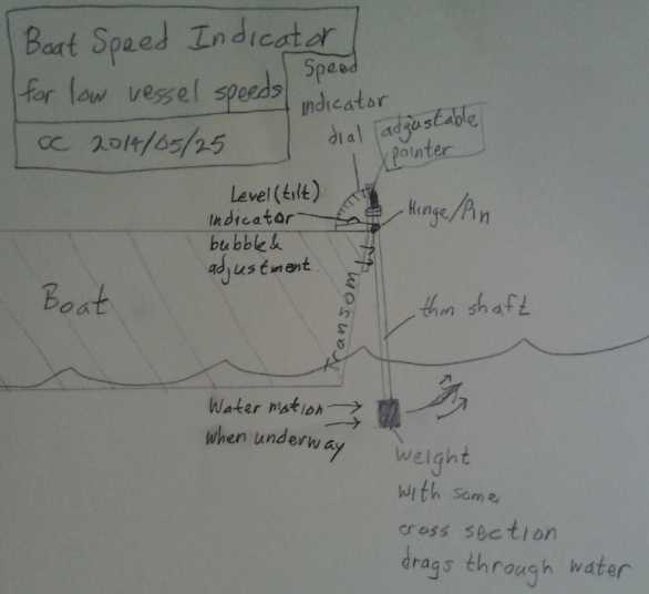
Boat Speed Indicator?
On the 25th, thinking about going fishing, I suddenly had
a new idea for a boat speed indicator for slow boat speeds. Instead of
a pitot tube, this one uses a weight on a pivoting stick. It would be
less susceptible to error from the depth of the transom changing in the
water with shifting weight or waves. But perhaps somewhat susceptible
to error due to the angle of the boat changing (bow to stern). A
disadvantage would be that the calibration would be individual
depending on the weight, length and cross section, and would have to be
determined, from some other speed indication. For somewhat higher
speeds, a heavier weight and a smaller cross section would be used, but
the whole design wouldn't be good for the sort of high speeds where the
typical commercial pitot sort of speedometer is used.
With the pitot tube and vertical plastic speed viewing
tube, the amount the water will rise (above sea level) for any given
speed is a known constant.
EV Individual Battery Monitor
On the 10th I drove the EV Mazda a fair distance, and the
voltages seemed to me to be suspiciously low after too short a
distance. Again I couldn't tell if it was all the batteries getting a
little low together or one problem battery getting very low. I measured
them after I stopped, but nothing seemed amiss. Then, having left it
unplugged for the tests, I forgot to plug the car in and it sat
uncharged all night.
Again a monitor showing the state of each battery would
have eliminated the need for the time consuming checks afterwards and
would have immediately disclosed any problem during the drive. The next
morning I got enthused and decided it was high time to make it.
First I itemized the chief challenges:
1. There aren't 12+ analog inputs on most microcontrollers, and I
didn't want to do some .5mm spaced chip with dozens of pins. I decided
to make the monitor do only 6, 7 or 8 batteries - however many pins
were available. One can install two units to measure 12 batteries, or
else measure 24 volt steps instead of 12, which should at least narrow
down problems to one of two batteries.
2. The voltages are high and floating. Best to insulate everything well
and have nothing metal the user can touch.
3. Each battery is at a different voltage than any other compared to
the circuit. This means different levels of attenuation required and
different voltage ADC rez for each one.
4. The little color display (128x128 pixels) would be a challenge both
to wire and to program. The leed spacing, 12 fingers in less than a
centimeter, will be a real challenge to my coarse toner transfer
circuit board techniques. One would expect there to be a connector made
to plug it into, but I haven't found it.
5. Control pushbuttons. I decided these would be the capacitive type -
just little interleaved fingers of circuit board that are touch
sensitive under software control.
Just writing these out caused much of my zeal to
evaporate.
Nothing was especially hard (except wiring up the display), but it
adds up to a considerable project. As I started in on the PCB design
and it started getting more complex than I'd hoped, it became apparent
that it was going to take considerably more time than I was bargaining
for... and I quit. On the 13th I decided to just buy a bunch of those
tiny, cheap 3-30 volt 3 digit LED voltage displays, mount 12 of them in
one panel for the dash, and hook one to each battery. The colored bar
graphs would certainly be superior, but the voltmeters should fulfill
the essential requirement, at the cost of distracting the driver
substantially more to read all those numbers than to glance at bars and
make sure they're all green and even. (Really I barely have time to
glance at the overall volts, amps and amp-hours now and then.)
Anyway, I've defined the color display for the circuit
board
layout program, which I also want for the fridge, heat pumping and
solar
controls, and I got a start on the circuit board layout if I change my
mind. It would be an excellent product. I may work on it occasionally.
Oh, to have people I could farm out some of the work to!
The little three digit LED voltmeter displays arrived on June 2nd.
I decided to mount just 4 or 5 in a small plastic panel with CAT plug
pins on the back to plug them into batteries, and connect them to
whatever batteries seem most vulnerable or suspect at the time, and
maybe use the 24 volt idea to cover a couple more than the number of
displays. Of course, that won't show unexpected problems in the other
batteries, like unnoticed capacity deterioration, or unplugged or
non-functional chargers.
Hopefully, by monitoring the (presumed) weaker batteries,
I'll be able to extend the driving range of the RX7 (also see next -
lithiums in RX7) by knowing whether it's time to quit as I normally do
now just in case, or whether there's some more safe life left without
possibly damaging one. More on this hopefully small project, I expect,
next issue.
Lithium-Ion Cells
in Mazda RX7 EV
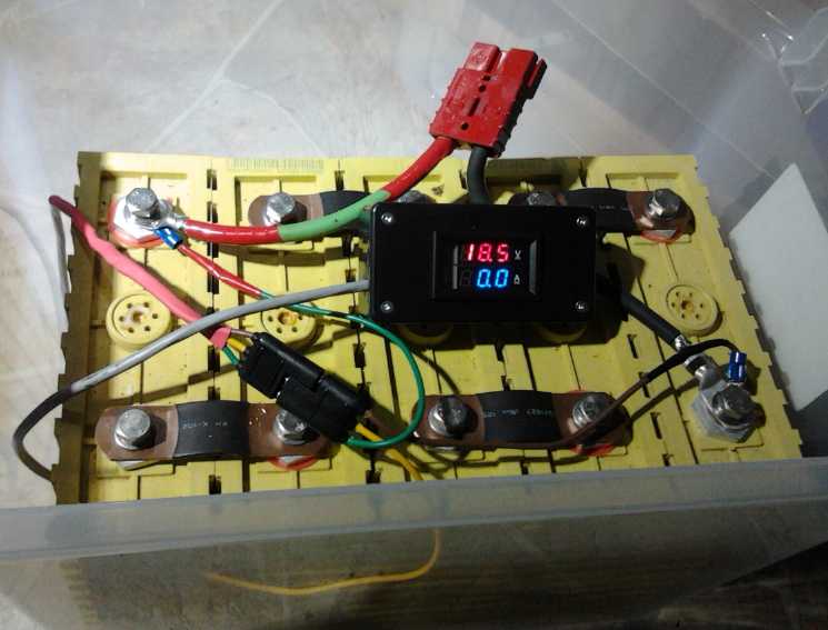
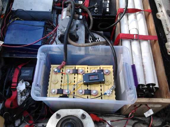 On the 28th,
having used an 18 volt bank of lithiums in
torque converter tests, and then having received a voltage-current dual
panel meter, I decided to try a bank of them in the RX7, where it
looked like one in its tub would just fit where a battery was missing.
This upped
the nominal voltage from 120 to 138, the highest yet, with the cells:
Li-ion 18V, NiMH 36V, PbPb (size 27) 60V, PbPb (size 24) 24 volts. Most
of these are about 100 amp-hours rated, except the size 24s are maybe
75-85 with lower current drive, and are surely now the limiting factor
in the car's range, but larger ones won't fit where they are. If it had
144
volts of size 27s (in good condition) it should theoretically have
35-45 Km range according to Canadian Electric Vehicles, which is much
more than I've actually had to this point. Going up to 138 volts should
help.
On the 28th,
having used an 18 volt bank of lithiums in
torque converter tests, and then having received a voltage-current dual
panel meter, I decided to try a bank of them in the RX7, where it
looked like one in its tub would just fit where a battery was missing.
This upped
the nominal voltage from 120 to 138, the highest yet, with the cells:
Li-ion 18V, NiMH 36V, PbPb (size 27) 60V, PbPb (size 24) 24 volts. Most
of these are about 100 amp-hours rated, except the size 24s are maybe
75-85 with lower current drive, and are surely now the limiting factor
in the car's range, but larger ones won't fit where they are. If it had
144
volts of size 27s (in good condition) it should theoretically have
35-45 Km range according to Canadian Electric Vehicles, which is much
more than I've actually had to this point. Going up to 138 volts should
help.
First I (at last) put together the charger. It wasn't a
good afternoon to try it out, because I had to drive about 3 miles to
an evening appointment. I drove around the block. Performance was
great, but I found that the lithiums had dropped in that short distance
from 18.7 volts to 16.7. They aren't supposed to be driven below 3.2
volts per cell, or 16 volts. They should have had at least as much
reserve capacity as any other battery in the car. Why they should be
down so far so fast was puzzling, and bode ill for a longer trip. I
decided to leave them installed and I checked the overall voltage on
the meter frequently. It's hard to tell what 18 volts of 138
volts is doing, but it seemed good enough all the way that I didn't
stop. At my destination (where I charged it almost 2 hours), and then
at home again, I measured the voltage on arrival and found it was about
16.4 volts. Evidently it drops to around that level rather soon and
then drops little for quite a while. After a trip or two, all 5 lithium
cells read exactly the same voltage (3.31v).
With the higher voltage (and warm weather), the car uses
less amp-hours per
mile - typically 1.8 to 2.3 instead of 2.2-2.5. It's as many
watt-hours, but the additional
voltage/cells will take it farther before the batteries are depleted.
On the 31st I dared a trip to Hillside mall, the farthest
destination yet with nowhere to plug in while there. On the return trip
the voltages were still high enough that I took a detour to another
store, and the whole trip was the farthest between charges yet, 7.8
miles (12.5 Km). On June 4th I made almost the same trip, but took a
detour to specifically extend it, to 9.0 miles (14.5Km). The lowest
batteries (the two size 24 PbPb s and one of the 90 AH NiMH s) were
getting down, and without an individual battery monitor it's dicey to
test the limits too far - you can't be certain when the weakest one(s)
starts being driven too low.
It should also be pointed out that Vancouver Island is pretty hilly and
Victoria city traffic is frequent stop and go. With flat ground, or
fewer stops and starts, or both, the car would consume substantially
less energy.
New Concept: Lightweight Air-Aluminum
Batteries for when regular cells are used up
Alcoa (aluminum company, of course!) has a new plan for
adding air-aluminum cells to EV s. Aluminum has an enticing amount of
energy as a negatrode, a light atom whose alkaline reaction; Al + 3
OH- => Al(OH)3 + 3 e-; moves 3 electrons, at -2.33
volts. (Compare with my 'super energy' rechargeable manganese reaction;
Mn + 2 OH- => Mn(OH)2 + 2 e-; just 2 electrons at -1.5
volts.) I don't know how they prevent the reaction from occurring
spontaneously at such a high voltage, but one assumes they have worked
out some means.
The idea of non-rechargeable cells in an EV has held
little appeal to me, but Alcoa's plan seems very good: Rather than
having
these lower cost but non-rechargeable cells used for regular driving,
they would be the "spare tank" reserve, taking the car as much as 1200
Km farther than the regular rechargeable batteries will take it. When
the aluminum is running low the cells are replaced (or the aluminum in
them is), but that wouldn't
happen except after some accumulated mileage of long trips - trips that
would
otherwise have been impractical or at least less practical in the EV.
It replaces the need for a gas engine (plug-in hybrid), stopping too
often to charge, or having to make the trip in a gas burning car
instead.
Electric Caik Motor: Ready-made
Rotors!
At Princess Auto I found a '7.8" brake rotor disk' fitted
for a 1" shaft for 35$. It's machined nicely and it fits nicely in the
Electric Caik motor housing, and the center takes less space than the
"H" bushing type. In fact, I think I could make the Caik motors 1/2 to
3/4" thinner, under 4". (This should also be true for the smaller "AJ"
size bushings that I recently ran across. Why do the stores keep these
things in the back so you don't find out they exist?) The textured
surface should give the epoxy a better grip than smooth steel to hold
the magnets on. The price contrasts well with an "H" taper lock shaft
bushing for 10-15$ plus having a 7.5" steel rotor cut by abrasive
waterjet for 35-40$.
One possibly negative attribute is that the disk plate is
thinner, about 3/16" instead of 1/4". But I don't really know what
thickness is required to complete the magnetic circuits of the
supermagnets nicely anyway, and just picked 1/4" owing to some gut
sense
of proportionality. I doubt any difference will be noticable. Also for
some reason, there's a key slot, but no set screw hole(s) at the shaft
to lock it in place. That can be remedied.
Other Green
Electric Equipment Projects
Peltier Module Heat
Pumping/Refrigeration
I really hoped to bring this project to some sort of conclusion for a
while early in May, with some new '24v' peltier modules I'd ordered in
April. If I had to work on it, I wanted it to be on the still unmade
solar
control. It was not to be, and the fridge is barely staying cool.
In the warming spring weather, the TEC12706 peltier module
I had put in temporarily continued to barely keep the fridge cool to
7°c, making only a little ice in bottom of the water tray.
On the 7th I got the "24 volt" peltier modules, numbered
C2406. Unfortunately I could find no specs on these units - only the
same text as at DX.com, repeated on several other web pages. It can't
be a
24
volt unit at all, as it draws 6 amps at 12 volts. Most peltier
modules say how many thermocouples are in them and their rating, eg, a
TEC12708 has 127 thermocouples (in series) and is rated at 8 or 8.5
amps. If this
one has only 24 thermocouples either they're a completely different
material or it
should be rated for about 2.8 volts. If on the other hand it has 240,
that would make it a 28 volt unit, pretty much as advertised... but it
doesn't behave that way. It acts as a 12 volt unit, despite the text.
Installed
in the fridge, it drew 5.25 amps (almost 70 watts at 13 volts) and soon
had the heatsink up to 37°c, but seemed to be cooling about well as
the previous unit. It became apparent I had merely replaced one 15v, 6a
module with another. I tested all three units and they were the same.
When I momentarily put 24 volts across one, it drew at least 12 amps.
Furthermore, I then tried the three 4 volt units from the
same order, the
C0405 s, thinking to make a 15+4 volt double unit. They seemed to be 4
volts,
but they only drew 2 amps instead of 5, which wouldn't pump enough heat
or match any other modules I have. If one pumped 5 amps through them,
both sides got warmer, tho unevenly.
This is the first time I've got goods from dx.com that
aren't as advertised, but needless to say I'm not very happy with it.
So I was left trying different things to get decent
cooling, when I wanted to be doing other things entirely. I tried
mixing a lower voltage TEG module with a TEC12708. But it only dropped
it 2.5 volts, and it was thicker, which made it very difficult to get
good thermal contact with the other, main, module. There wasn't room on
the heatsink for 3, 4 or 5 TEG modules to get to a good 12 volt working
voltage.
I found another source
of peltier modules at aliexpress.com, which seems to be an alliance of
east Asian companies - apparently even factories - who ship small parts
directly through the post office, with a central payment system.
Searching hundreds of modules shows only a few that aren't 127
thermocouples for 15 volt ratings. Then, the promising looking ones
were all sold in lots of 10 for over 100$, so one can't try out a
couple of each of 2, 3 or 4 types and find the most satisfactory - if
it exists - without spending a lot of money. I couldn't find any like
the CP85338-7108 - 8 volt
one I used in the 15+8 volt dual module system that worked so well
until the 8 volt module got cracked. (71 thermocouples, I think.) All
the "cheap" peltiers at Digikey have gone up from 17$
to 22, when one can order similar from China for around 5$ - and the
Cui ones at
Digikey are probably made in China anyway.
The frustrating ubiquity of the 127 element/15v peltier
modules was
such
that I started thinking that using them at about 7-10
volts via a DC to DC converter may be the only way this is going to
work well, and that the converter losses would have to be accepted. The
converter could be simplified, and it's output voltage made
programmable, as a programmable part of the microcontroller based
fridge control circuit.
I ordered a very large 62x62mm, 15 amp module. (20$ each,
package of two) That should pump plenty of heat even at half voltage.
(Unfortunately I can't fit two to put them in series - unless I put one
on the underside of the copper bar and use two heatsinks and two fans.)
And for solar use with variable voltage, with extra cooling power one
might adopt a strategy of aggressive cooling to freeze all the ice
during
the day when the sun is providing lots of power (COP be dammed!) and
much less if the supply voltage is down a bit and (hopefully) none at
night.
Flat Panel LED Light
I continued looking for suitable supplies for this project
-- and found them.
Supplies seem to often be much the biggest issue as soon as you're
looking for something not commonly used by many other people and you
don't have
a budget to order from some pricey specialty supplier without giving it
serious consideration first. Consider that I was paying 10$ plus for
LED emitters for the globe lights, with two emitters per light. Things
became much more economical in principle when I ran across smaller
emitters for 20¢, even though 9-15 would be required per light.
This time around I found "Aliexpress.com", an
umbrella sales and marketing agency for many Chinese/Asian export
dealers. White LED emitters similar to those for 20¢ at dx.com
were to be found at
outlets here as low as 10¢ - and with better brightness specs,
according to the numbers given.
There were also several types of emitters for plant
growing lights. They cost a lot more - 30¢ to over a dollar - but
were still affordable since people will pay extra for plant growing
lights. Of course, my lights would be pretty low output for plant
growth,
but the larger ones appear to be quite pricey, so there may be a market
for small, lower cost ones. (Seedlings? Shade-loving plants?) It seems
Earth plant photosynthesis largely
uses two very specific wavebands of light: near ultra-violet to blue in
the band 400-450 or (other sources) 410-470
nanometers (foliage), and red to deep red in the band 640-675nm
(promotes
flowering). Thus it seems
green light is pretty much useless, and white including sunlight is
good only insofar as it contains the blue and red. The balance between
these two bands, it seems, varies with the time of day and with
the season - which may be how plants 'know' when to flower, each at its
'preferred' time. (We tend to think the mechanisms of life are simple,
and it's postulated they all came about by random chance rather than by
design - here's just one more amazingly sophisticated one!) For basic
growing, it's probably enough to have a mix of the two colors, and for
just
leaf growth, just blue.
The blue emitters seemed to all be about 450nm or
'445-455nm'. I'd have preferred something nearer the middle of
the 400-450nm band, but I didn't see any. (After I'd ordered I found a
couple of 430nm emitters.) There were 1 watt and 3 watt
blue emitters... which seemed in my quick scan to have almost the same
lumen figures...
so I ordered some 1 watt 450nm s. In the red were 'high efficiency'
630nm, and 660nm. I chose to get some of the latter as that's at the
center of the band for plants. 630 may perhaps be close enough, but the
660 s specifically said "plant growing".
Then, the 1/8" translucent acrylic plastic was said to
absorb 1/2 the light. But LED s need diffusion. Those
tiny, intense emitters, doubtless harmful to vision, leave sharply
defined spots in front of your eyes, as is typical of too many LED
lights. I was given a sample of a
thinner piece at Plexi-Klass locally, and it seemed to let more light
through. Making a new case for the prototype with it, the light seemed
substantially brighter. Maybe it blocks 20 or 30% of the light. One can
see where the emitters are, yet they're diffused into 'blobs' of light,
not the intense sharp spots. That's success! It's probably better
transmission than my globe lights (for which I had never given the
issue any thought), or at least as good. Lamp shades for incandescent
bulbs absorb light too, some of them a high percentage.
Getting an even glow from the whole light surface would be
tricky with my design and these somewhat 'aimed' emitters. I don't see
it as a real problem. The cure might be worse than the disease. Other
than a thick diffuser blocking much of the light, one might put in a
thin sheet of something to start the diffusion before the bottom cover
- two or multiple layers spaced apart - but the fixture would probably
have to be 2 or 3 or 4 inches thick. (Optimum distance for the single
thin cover seems to be around an inch.)
I disassembled a Chinese flat panel unit that had an even
glow. It had the 60 emitters in strips of 30 along two opposite edges,
shining inward into a 1/4" thick clear acrylic sheet, with a thin
translucent sheet under it. Held up to a light, their translucent sheet
looked just a little brighter than my sample and had similar diffusion.
(Rats, where'd they get it? I suspect they had it made, optimized for
lights.) The aluminum outer edges act as the heatsink for the emitters.
Again no one uses such thin 'translucent' acrylic much -
possibly it's good for almost no other purpose -
and to buy any I had to order a whole 4' x 8' sheet. I was lucky to
find a sample of acceptable material and get it locally, and it's
doubtless much cheaper per
square foot in whole sheets.
There were
also 15cm x 20cm single sided circuit boards at
aliexpress.com, again for a low cost, and I ordered a pack of 10 as
they were about the right size for the lights. Luckily I didn't order
more, because later I thought of simply using thin sheets (.016"?) of
copper in strips, with the LED emitters soldered between them. (When
they eventually arrived, except for the top one, they also appeared to
be cheap phenolic boards, where I'm pretty sure the site said epoxy.)
It'll
cost a bit more, but the first prototype ran too
warm, and copper sheets will be better heatsinks for the emitters,
absorbing heat better and radiating it well from both faces. The gaps
between strips will improve airflow. And it solves the problems with
etching the large boards with large copper areas. Just the end strip
will be circuit board, for the control circuits and connectors.
I'll also improve the cooling airflow, with a ventilation
gap between the top and the ceiling, formed by the mounting tabs.
There I left it on the 9th, awaiting parts, intending to
get on with the torque converter. But I sent someone who was going past
the
rather distant store anyway, to get 2 thicknesses of copper to try out,
.010" and .016". I shouldn't have asked for 3 square feet of each, as
the bill came to 85$. But I got to try it out immediately. Next the new
circuit board "strip" is to be designed and made. But I switched to
working on the torque converter.
Electricity Storage
Turquoise Battery Project
Carbon Black powder... from old dry cells
Having found "aliexpress.com" with a multitude of Chinese
and East Asian businesses listing their products under an overall sales
system umbrella, I checked for "conductive carbon black powder". A
company had what appeared to be the perfect 1.5Kg bag of high purity
powder for about 80$c. But when I went to buy it, the web page said
"can't ship to the selected country" (Canada). They were the only
company selling carbon black, and it seemed none of their products
could be shipped to Canada. No reason was given, nor any alternative
suggestion. Was this some strange delivery issue? Did the president of
the company hate Canada? Or was it some stupid Canadian restriction
passed by those who are elected to represent our interests, to solve
some little problem someone once had, or even might potentially have,
and now in company with thousands of other stupid restrictions
arbitrarily impeding
the ability of all Canadians to do anything but sit and watch TV all
day? Or even to abet some corrupt corporate interest(s) in relieving us
of our money?
Unfortunately, Canadian government interference seems the
most likely. Churchill said
something to the effect that if 10,000 laws were enacted, people would
lose their respect for the law. I suspect there are far more laws than
that today, and I feel more and more that the bulk of them simply limit
our
freedom to do useful things, without having any proportionate - or even
discernible - benefit to society. But I digress.
I finally decided that the path of least resistance might
be to get old dry cells and use the MnO2/carbon black (or graphite) mix
in place of the suspect graphite and some of the KMnO4. It wouldn't be
as concentrated as desirable and the whole un-optimum mix propotions
can't be exactly known, but at least
whatever carbon and manganese is used in them is pure, battery quality,
and won't cause self discharge.
So guessing the actual percentages, apparently the amount
of carbon used is a little over 50% by volume, but carbon being
un-dense, that's more like 30% by weight. If I take 40 grams and add
other ingredients it should make some semblance of an appropriate mix:
28g - MnO2 (or Mn2O3 or MnOOH or Mn3O4 or Mn(OH)2 in various
proportions depending on discharge state)
12g - carbon black (substantially less than I'd like)
18g - KMnO4
18g - Monel
18g - Ni(OH)2
6g - Sm2O3
(Rats, I didn't get to it!)
Lithium Ion
Battery Sets: 2 odd cells out of 11
 "18v" - really about 16v in operation - lithium
battery
"18v" - really about 16v in operation - lithium
battery
When I got the lithiums, I was a bit taken aback to hear
that they had self discharge and had to be kept topped up. I thought
that was a big argument against alkaline cells. Then, of the eleven 100
amp-hour lithium cells, which I got for the boat & Electric Caik
outboard, one seemed to
discharge itself much more quickly than the others, and one wouldn't
charge up to 3.8 volts, refusing to rise above 3.34 and soon dropping
back to 3.31 after charging for any length of time. The 'lossy' one had
to be charged to full separately after the other four in the 18v set
had finished.
This probably shows poor quality control, although the
'almost new' cells might possibly have been subjected unknowingly to
overdischarge or overcharge at some point. It also shows that the
individual battery monitor could be put to advantageous use even with
supposedly identical and ideal cells - that anything was amiss would
have been obvious instead of undetected.
Whatever the cause, I set the low voltage one aside. I had
thought to use that last cell as a token lithium cell in the Mazda
just to be trying out three distinct types of batteries in it: PbPb,
NiMH and Li-ion. That's now out. But I installed the best of the two
sets
of 5 temporarily as an 18 volt battery (really about 16.5v), making
120+18=138 nominal volts. That can be read above in the Electric
Transport section. It improved range and performance, making the
car more useful. After the second or third trip all 5 cells read
exactly the same voltage, 3.31v.
http://www.TurquoiseEnergy.com
Victoria BC