Turquoise
Energy Ltd. News #77
June 2014 (posted July 5th)
Victoria BC
by Craig Carmichael
www.TurquoiseEnergy.com
= www.ElectricCaik.com
= www.ElectricHubcap.com
= www.ElectricWeel.com
Features:
* Flat Panel LED Lights: production steps & a great 'cracked ice
texture' diffuser acrylic
* Turquoise Battery: Self discharge problem of positive electrode
eliminated!
Month In Brief
(Project Summaries)
- distractions - flat panel LED
lights - torque converter, manual transmission et al - Peltier woes -
NiMn
batteries: self discharge of postitve electrode solved - VEVA Electric
Vehicle
meetings.
In Passing
(Miscellaneous
topics, editorial comments & opinionated rants)
- Ooops: 'unsold cars sitting everywhere' was in 2009,
not 2014. - ISIS & Iraq
Electric Transport - Electric
Hubcap Motor Systems
* Suspension for Bicycles! - Loopwheel and Shockwheel -
game changers for cycling and e-cycling?
* Application of my rim motor design to new wheel types
Other "Green"
Electric Equipment Projects
* Flat Panel LED Lights
- some more printed circuit board making techniques
- case production
- 'pebble texture' acrylic diffuser material gives great 'ice
cube' look, passes more light!
Electricity Generating (no reports)
Electricity Storage - Turquoise
(NiMn) Battery Project etc.
* Positive electrode self discharge problem solved: it was the impure
graphite powder.
No Project Reports on:
Variable torque converter transmission, Peltier heat pumping, Lambda
Ray Collector, Magnet motor, CNC
Gardening/Farming Machine (sigh, maybe summer...
2015?),
Woodstove/Thermal Electricity Generator (may abandon),
evacuated tube heat radiators.
Newsletters Index/Highlights: http://www.TurquoiseEnergy.com/news/index.html
Construction Manuals and information:
- Electric Hubcap Family Motors - Turquoise Motor Controllers -
Ersatz 'powder coating' home process for
protecting/painting metal
- Preliminary Ni-Mn Battery Making book
Products Catalog:
- Electric Hubcap 4.6KW BLDC Pancake Motor Kit
- Electric
Caik
3KW BLDC Pancake Motor Kit
- NiMH Handy Battery Sticks, 12v battery trays & Dry
Cells (cheapest NiMH
prices in Victoria BC)
- LED Light Fixtures
(Will accept BITCOIN digital currency)
...all at: http://www.TurquoiseEnergy.com/
(orders: e-mail craig@saers.com)
June in Brief
Various things that needed
doing kept me from getting to green energy projects. One was the
reporting of last
year's project work. My T2 and SR & ED form and other things for
Revenue Canada (CRA) being now 3 months late, and containing a couple
of
things I didn't know how to deal with, I tried to get accountants to do
them. The first one looked it over and said it was too complicated for
him. The next one, after 2 short but
helpful sessions over about 3 weeks, looked everything over and said I
was closer than I thought, and that I should finish it myself to avoid
paying him a lot of money to redo it. A week of part time work finally
finished it
off and I put it in the CRA drop box (the only piece of CRA in town) on
the 24th. After that and an "overdue T4 Summary" I also got done and
posted, I
have only two more overdue things to file for CRA - for now.
Occupying another week's worth of effort (but spread out
over much
of the month) I assembled and wired ten 8-wire waterproof slip rings
for vessel winches under contract for AGO Electronics. Then there were
gardening (unfortunately not the CNC gardening machine), continued
setting up of the aquaponics greenhouse, and other home projects. And
weekly concert band rehearsals ending with a concert in the park and a
barbecue on the 28th. With my alto Supercorder I was of course
the only
one who has invented and was playing their own instrument. (I played
oboe parts, there being no oboe, and I doubled the flutes in places
because the conductor liked the fuller sound... "Flutes can sound so
thin!")
I sat down a few times trying to figure out a mold for the
big Electric Weel motor, and a new bicycle suspension-wheel
system led me to consider anew the best way to make a bicycle rim
motor. And I looked at the variable transmission and how to fit it all
together. However, little was done beyond playing with layout and
design concepts.
To finish this
subject, on July 1st I decided that even tho I finally have what I
think is a workable configuration for the variable torque converter,
there was still quite a bit of work to do to get it going, of which
virtually
none got done in June. To get the Chevy Sprint on the road I would --
hopefully only temporarily -- give up on it, and just go out and buy a
manual transmission. The Sprint would at least be bound to start moving
in first, second or reverse gear. And if I got a commercial motor
controller with more amps, say up to 300, 400 or 500, that just might
give it the power to put it on the street, and I would find out the
real limits of my Electric Hubcap motors. I've been saying they're
"4.5KW" or "5KW", but they might well handle 10KW or more for short
periods - or even for longer for all I know.
With the transmission out of the way, I could concentrate
on fixing up the bugs in my own motor controllers, and on designing and
making motors -- things I've been much more successful at so far than
the
torque converter transmission.
Since that was Canada Day and everything was closed, I did
the shopping the next day, the 2nd. As I bought the transmission and
looked at it, I
realized that I still didn't have the clutch, and the flywheel clutch
plate for the motor side (Duh!), and when I got home, that all the
mountings in the car
were different. I might have to do some welding to fit it on. More and
more I wish I'd found a manual transmission Sprint in the first place.
But if what's missing is a clutch... didn't I just create
a new sort of centrifugal clutch? Perhaps I could use that. Let's
see... how hard might this be? Am I still going to be experimenting
with mechanical transmission stuff after all?
The big 62x62mm, 14 amp
peltier modules arrived around
mid-month and I installed one. It didn't work very well and I took it
apart and redid it, checking for trapped bits that might push the face
away from the heatsink or cold bar. That still didn't do it. I also
attached the control unit I'd bought with it, but since it never got
cold enough to shut off, it didn't do much except make a loud, annoying
beep when the power came on, and show the temperature. It may still
have a setup problem, so I'm not ready to say the module is bad. But I
didn't have
time to keep frigging around with the fridge system, so I have nothing
definite to report.
But near the end of the month, I got a couple of
interesting things done. I made several cases for flat panel LED lights
to
get production going - at least for some samples (and 3 or 4 to install
myself), and I started on the workings for a second light. Then,
looking to see what Industrial Plastics had on hand that I might use
for motor molds, I found instead some "cracked ice" pattern translucent
-
almost transparent - thin acrylic sheets to use for light diffusers.
They look fantastic when the light is off, but almost a bit as if they
were dirty when the light is on. However, they let more light through
than anything else I've seen, and one doesn't normally stare at lights
that are on. I think they'll work out great!
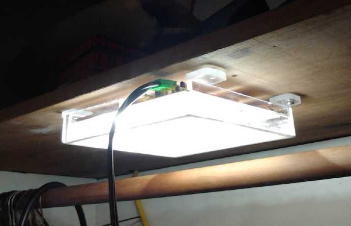
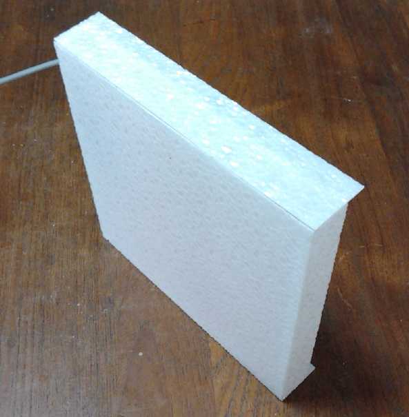 "Cracked ice" plastic diffuser prototype
light
"Cracked ice" plastic diffuser prototype
light
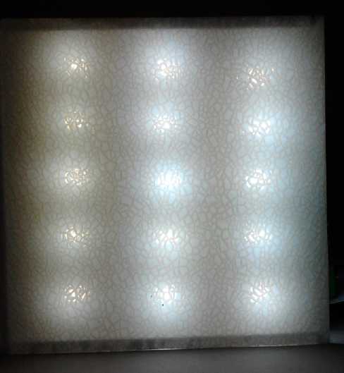
Turned on: Sufficient diffusion with high light transmission
(Left row: old emitters (4500K?). Mid, Right: new brighter, bluer ones
(6000K?).)
I also, finally, made a Ni-Mn battery on the 29th and 30th
to see if avoiding the art store graphite powder would solve the
self-discharge problem of the positive electrode. It did.
Unless
there is still deterioration of the posode over time, which I believe I
solved by increasing the ratio of nickel oxides to manganese oxides (to
form nickel manganates rather than potassium permanganate as the cell
charges and discharges),
the "nickel-manganese moderately alkaline" battery chemistry is now
known
to work with nothing to say it might be impractical for commercial use
for any reason.
But I still don't have a proper battery cell. For some
reason the
negative electrode unexpectedly didn't work right in this particular
cell - not even
in the fridge. Even its zinc powder wouldn't hold its charge. I must
have done something wrong somewhere -- the manganese negatives with
trace additives zirconium silicate and antimony sulfide have been
working well until this one. I'll make
a new one soon and demonstrate for certain everything working together
properly in the same cell.
Finally, in June just after the May newsletter, and on
July 2nd, I went
to meetings of the VEVA electric vehicle - Islands chapter. At the June
meeting was a really well done Honda Del Sol conversion. The July
meeting had a big turnout with quite a lot of electric bicycles.
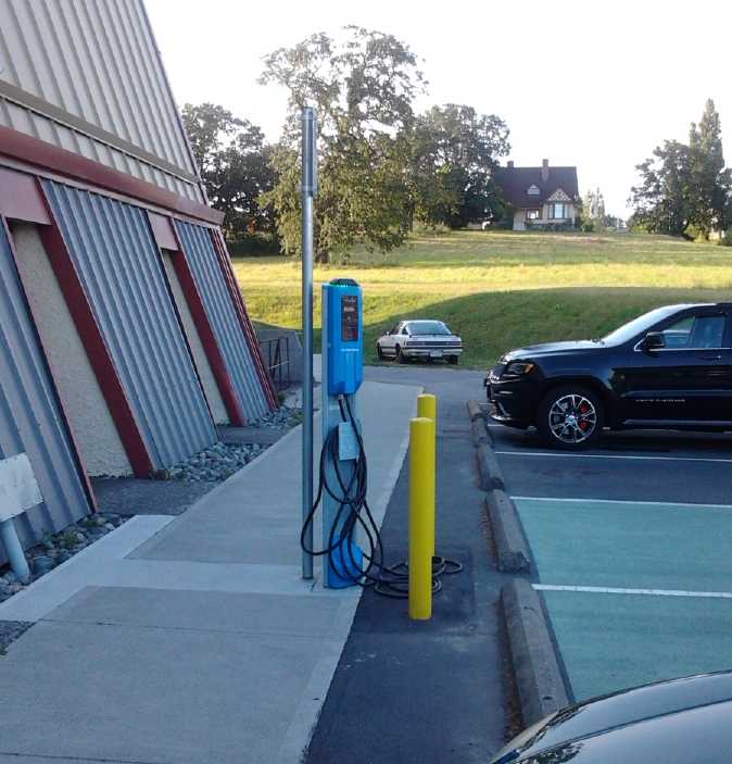 Is there some irony here? The 240 volt
J-1772 electric car plug-in stations look nice, but
Is there some irony here? The 240 volt
J-1772 electric car plug-in stations look nice, but
I had to go park the Mazda, the only EV on the premises, on the lawn
where my 70 foot
extension cord could reach a regular 120 volt outlet, potentially
risking a ticket or tow-away.
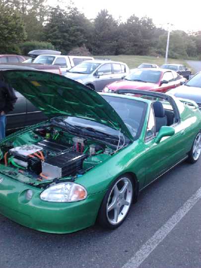
Honda Del Sol EV conversion, very professionally done by an auto
mechanic.
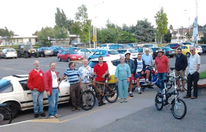
The July 2nd VEVA-Islands meeting. I gave some rides in the electric
Mazda, and
I got to drive the Nissan Leaf,
and leave all the other cars far behind when I took off from a traffic
light.
In Passing
(Miscellaneous topics, editorial comments & opinionated rants)
"Where Unsold Cars Go To Die"? (mistake from last issue)
My apollogies... I should have checked more carefully. The article on
unsold cars was evidently incorrect. The 'countless acres of cars'
pictures were real enough, but
they were from 2009 after the 2008 'crash'. And car makers did stop
production as inventories piled up.
http://www.snopes.com/photos/automobiles/unsoldcars.asp
I must be more careful not to believe everything I read.
 This may well be the type of storm drain that
was
under
the grassy knoll
This may well be the type of storm drain that
was
under
the grassy knoll
where people heard the shots coming from when John F. Kennedy was shot,
and where (I now hear) a puff of smoke was seen in the air after
the
shooting.
It certainly does appear to be a mafia hangout!

When this was made, these prices were probably intended to shock.
They're now the actual ballpark prices for a small car,
and in a year or two they may look like a real bargain.
While the real background story behind the news reports
seems unclear so far, one hears rumors - or is it fact? - that as
ISIS/ISIL (however it formed and whoever provided their military
training and weapons) penetrates Iraq, it's perpetrating murders and
atrocities. So still more inhabitants are fleeing their homes --
joining
Iraqis who fled previously and the one half of the Syrian population
driven from their homes.
How then is this group better than those who invaded
before them in 2003, and the government they set up? Now we have suni
Muslims persecuting shi'ite Muslims instead of the other way around.
(And all of them persecuting Christians.) Sadam Hussein was the last
ruler of Iraq who kept internal peace between the various interests and
religious groups (ditto for Moammar Kadafi in Libya).
Tolerance, forgiveness, patience, benevolence... love...
these are the leadership qualities that would rally citizens to the
cause, or at least permit peace and stability to develop. Instead it
would appear the
populace only has one more prejudiced, dictatorial, manipulative and
well armed group rampaging through their towns and cities, to hate and
fear.
But perhaps one should look beyond the specific case,
broaden the
perspective and ask oneself, "What are the conditions that favor the
formation of such extreme groups?" Is it an isolated event unique
to Iraq, or is there some common thread? How does it relate to the US
led invasion of 2003, US and international relations and events today,
and to the continual American drive to get middle eastern oil and to
prop
up the "petrodollar"? And what drives the aspirations of various
groups around the world to want to separate and form their own
administrative regions (countries) in the midst of growing global
connectedness and political amalgamations such as the European Union?
I think that implicit in
all of it is unfairness, on many levels with many indistinct
boundaries,
and the hope that by becoming independent, more localized control might
somehow
address the unfairness. But (as Kennedy said) "We all drink the same
water; we all
breathe the same air." Mostly today the real divide is between those
with wealth, power and influence - "the 1% of the 1%" - and the rest of
us, who have lost or are losing it all to them. It's a system that
increasingly people simply want out of, and which is starting to be
sidestepped at the individual level by those who are starting to
recognize that they are being manipulated and
fleeced by the greedy.
One suspects that as economic conditions worsen globally,
hardships in various forms are likely to spread. Certainly there are
governments,
including nominally democratic ones, that are out of control
oligopolies/corporatocracies/cleptocracies that badly need to be
replaced. Our
institutions of
governance have structural weaknesses that have allowed corrupt
gangsters to
seize control over them. The ever increasing number of laws and rules
for the populace
don't apply
to the rich and powerful. Not only the gross unpunished fraud robbing
the middle class of its wealth, but the 25 or 30 banking executives
murdered in the last few months (added to the regular persecution of
journalists, politicians and inventors who would "buck the system"),
with no investigations or charges
laid, attest to that. Democratic power by the citizenry has been
essentially lost*.
Can we avoid the temptation to blame each other and split into factions
ruthlessly vying for power or create smaller geographic groupings, and
instead attempt to solve the structural
problems
of our unsustainable social institutions?
It's said there are three core values that socially
sustainable institutions must foster: Quality of Life, Growth, and
Equality. I've mentioned before how our present institutions are unable
to grow
and change to meet the needs of the day, putting our civilization at an
evolutionary dead end. And the other two values, quality of life and
equality, have been under ongoing
serious attack for generations. As individuals we don't have the
continuity to look back 100 or 150 years to realize the many ways we've
been socially regimented, economically controlled and otherwise... is
this the right word?... enslaved. We believe the conditions we're
born into are just and right, "that's the way it is", and as we see
petty measures taken that
restrict freedoms and liberties bit by bit, and adverse conditions
gradually develop, things that we don't really
agree with or like, in the news and around us week after week, we are
like the frog who doesn't notice that the temperature of the water
he's in is slowly, slowly, rising and rising. It all seems normal and
the frog doesn't jump out, and finally the water is too hot and he
dies.
* See of course my booklet Fundamental Principles
of Democratic
Government - Towards Utopian Systems of Governance
at www.saers.com/recorder/craig/FundamentalDemocracy.html
for some ideas.
Electric
Hubcap Motor Systems - Electric Transport
Suspension for
Bicycles
 Various means for
giving bicycles some shock absorption have been around for a long time.
There have been "typical" motorcycle type springs and shock absorbers.
Then there's a spring and shock that allows the seat to go up and down,
springing the rider's body without springing the bike itself. But
except for the inflated tire and padding in seats, these haven't caught
on much with riders.
Various means for
giving bicycles some shock absorption have been around for a long time.
There have been "typical" motorcycle type springs and shock absorbers.
Then there's a spring and shock that allows the seat to go up and down,
springing the rider's body without springing the bike itself. But
except for the inflated tire and padding in seats, these haven't caught
on much with riders.
Now "re-inventing the wheel" is an old saying meaning
wasting effort to create something that's already been created. But
maybe it was already a saying when wheels were round chunks of wood
with a primitive wooden axle and rubbing bearings. We may think of
wheels as "already done to death", but at various points they got steel
rims, spokes, rubber and then air filled tires, and roller bearings:
wheels have in fact been progressively "re-invented" many times.
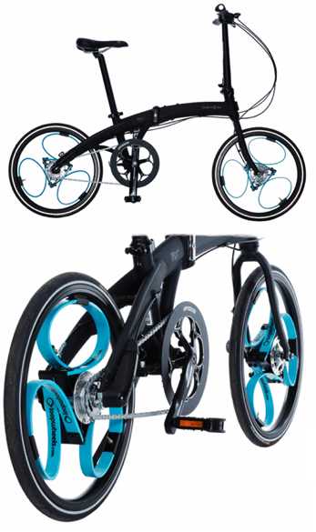
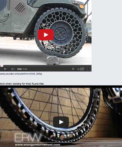
Here is another substantial new idea, seemingly invented
independently first in the UK then in the US: bicycle wheels with the
rim connected to the hub by curved leaf springs instead of by spokes.
This gives the bicycle a springy suspension within each wheel, and
makes the 'normal' bumpety-bump bicycle ride, jarring the rider at
every lump, crack and pothole, apparently even smoother than that of a
motorcycle. Suddenly bicycles -- and e-bicycles -- can be far more
comfortable to ride. Maybe such e-bikes will start replacing
"e-scooters" and "e-motorcycles"... and some riders may even decide
they can replace their cars, or use the bike and drive less.
The earlier invention would appear to be the "loopwheel"
from the UK. And it's not only invented, one can buy a bicycle made
with them. A BBC news report had the reporter riding pretty comfortably
on a rough cobblestone road. The inventor said he worked 4 years on the
composite material for the loop-springs. They're probably lighter than
spring steel.
Link: Loopwheels - For a
smoother, more comfortable bicycle
ride...
At 20" the Loopwheel is smaller than a typical
bicycle wheel, so simply replacing your crate's wheels isn't an option.
The second similar invention, the Shockwheel by
Chet Baigh, appeared on youtube in February 2013.
The ShockWheel
invention by Chet Baigh - YouTube
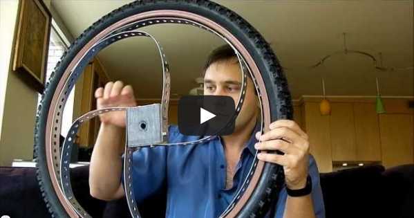 First concept-prototype Shockwheel
wasn't rideable
First concept-prototype Shockwheel
wasn't rideable
 Footage of the second one in use, including on
very large bumps, was the meat of the video
Footage of the second one in use, including on
very large bumps, was the meat of the video
The inventor had only done
a prototype on the front wheel, and doesn't seem to have posted
anything about it since except 'looking for someone to take it
commercial'. Nevertheless it looked like it was doing a very good job
in the video. And he said everywhere people stopped him to ask about
it, and even crowds gathered around. An observation is that the wheel
rim might need to be heavier steel or otherwise beefed up. On the other
hand, maybe not: the Shockweel has four support points while the
Loopwheel has only three, and on both, shocks to the wheels are in
effect cushioned by the springs.
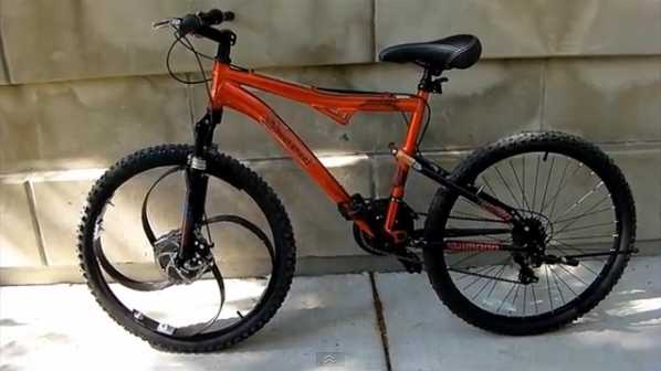
A big advantage to Shockwheel is that it's made to fit a
regular bicycle. I'm sure there'd be a gigantic market for retrofit
wheels.
Assuming it looked sufficiently robust and with any sort of economical
price, I myself wouldn't hesitate. And I might even ride more!
There have been other ideas for shock absorbing wheels.
But they mostly use flexing rubber or plastic parts, and I doubt if any
of them would last very well, or replace a suspension system as well as
the ones above. The one below at bottom may have metal springs, but as
shown it would only be good for small bumps - about like an inflated
tire. (But now I'm starting to think of the many possibilities!)
 I got these from some web site discussing
Shockwheel... somewhere
I got these from some web site discussing
Shockwheel... somewhere
Application to the Rim Motor?
Assuming these types of spring-suspension wheels are the
future of bicycling, the next question for me is: what about that rim
motor with the arc of coils attached to the frame, that I've been
planning to make? The magnet rotor ring was to mount on the spokes of
the wheel. Now there are no spokes, and also the rim bounces around
with bumps and dips on the road. The magnet rotor ring would bounce
along with it. This wouldn't improve alignments to the coils, and 1/2"
of sideways motion of the rim would have the magnets scraping the coil
housing.
This is doubtless going to call for some revisions to the
plan. Perhaps the magnet rotor can be attached to the hub. That would
make a single design, more applicable to a wider range of bicycles
anyway. But looking at a couple of bikes, I'm wondering if a whole
special wheel might have to be made to accommodate both the suspension
springs and the motor. But such a wheel would have double the
attraction to buyers: a smooth ride and power!
As occasionally happens, I may be ahead by not having
built this project yet.
Other Green
Electric Equipment Projects
Flat Panel LED Lights
My flat panel lights, being uneven in brightness across
the face, may have a bit of a hard time competing with the fairly even
glow of the Chinese flat panel lights. At first I thought they might
not really be competitive. But they'll probably be brighter
per watt, and it's a design I can make relatively easily and offer at a
competitive price. Some "cracked ice" diffuser plastic I found near the
end of the month looks nicer when the light is off than flat plastic,
and transmits more light than anything else I've found.
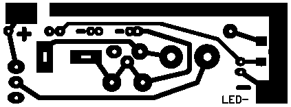
On the 8th I
designed a PCB for the other components. It was mostly a modification
of the previous board as to component placement, dimensions and
connections, but I added a receptacle for typical power adapters ('fat'
pin, center '+', 12v) in addition to the CAT standard plug pins, and
simply in parallel to them.
Circuit Board Making Techniques (the continuing search for
better processes)
 I made a board
the next morning. Instead of printing the
artwork on thin, glossy magazine paper, I printed it on "toner transfer
paper" from "Fab in a Box" (www.pcbfx.com). The first image transferred
poorly,
but I turned down the temperature of the iron and the next one looked
good. It transferred well and the backing paper virtually fell right
off
after a brief soak. All the toner and no paper fiber was deposited on
the board, which seemed to be an improvement over the magazine paper.
It was again a bit light with missing spots... at least partly because
I
forgot again to print "darkest", which in turn is because the print
darkness adjustment isn't shown in the multitude of print setup
options. It's well hidden and doesn't have a big range. The on-line
instructions said they preferred a laminator to an iron, and the
instructions mention some other 'foil' product of theirs that I didn't
buy, to laminate on after the toner transfer.
I made a board
the next morning. Instead of printing the
artwork on thin, glossy magazine paper, I printed it on "toner transfer
paper" from "Fab in a Box" (www.pcbfx.com). The first image transferred
poorly,
but I turned down the temperature of the iron and the next one looked
good. It transferred well and the backing paper virtually fell right
off
after a brief soak. All the toner and no paper fiber was deposited on
the board, which seemed to be an improvement over the magazine paper.
It was again a bit light with missing spots... at least partly because
I
forgot again to print "darkest", which in turn is because the print
darkness adjustment isn't shown in the multitude of print setup
options. It's well hidden and doesn't have a big range. The on-line
instructions said they preferred a laminator to an iron, and the
instructions mention some other 'foil' product of theirs that I didn't
buy, to laminate on after the toner transfer.
When I etched the board I wasn't very happy with the final
result. The general outlines seemed sharp and well defined, but the
copper wasn't shiny and buffing it didn't help. Under a magnifying
glass, many areas that were supposed to be solid copper were etched
partly or completely through in a fine "woven" or "checkerboard"
pattern. The iron
may have been too hot or cold, and the print too light, and I didn't
have the 'foil' stuff. So I thought I probably hadn't given it a fair
trial.
On the 12th or 13th I was driving by Microsec R & D,
where I heard Ed had switched to "a better way of doing boards" a few
months ago, and I stopped in. It turned out he was using the same toner
transfer paper I was trying out, but using a laminator
instead of an iron. He had some very nice looking boards he'd recently
done and said it was as good as the old photo process. And he had the
'foil' as well, but said it just seemed to be a nuisance and he wasn't
using it. "Run it through the laminator 10 or 12 times." It also turned
out that laminators are no longer large machines doubtless costing many
hundreds of dollars as they were in the 1980s when I used to deal with
them, but could be had as a little on-off plastic device for 50$.
50$?!? Why was I bothering with an iron?
On the 15th I printed 9 copies of the artwork in a
vertical column. The print on regular paper was fine, but on the toner
transfer paper it got worse and worse from top to bottom. I did the top
3 "V2" boards - the rest were unusable. The transfer via 12 laminator
passes was good except in a few spots that inexplicably stuck to the
paper instead of the board. I used a felt marker pen to touch these up.
The boards came out no better than the previous ones, with the same
crosshatch patterns in the copper.
Surely the printer was the main problem then. After a
search, I found where to adjust the darkness, under the heading
"Printer Setting" -> "Graphic" -> "Color" -> "Manual color
adjustment". I moved the "black" bar all the way to the right... but
did that mean 'darkest', or 'lightest'? There was no indication. So I
did a test print there, then moved the bar all the way to the left and
did another.
The first one was slightly darker, so I set it back. But
under a magnifying glass, the same crosshatch pattern that was plaguing
the circuit boards was visible on the paper in both copies. Humpf! I
suppose that with the glossy magazine paper and the iron, there was
just enough smear, or enough stuck paper fibers, to smooth out the
pattern and fill the voids. The special toner transfer paper gave
higher resolution that showed the printer's flaws. Evidently with my
printer I should stick with the glossy magazine paper.
Judging by the results, with even the fine crosshatch
pattern showing up clearly, I did better with the iron, carefully
pressing each and every spot right near the edge of the iron, and
lifting the iron to move it, than I did with the laminator. That was a
bit of a surprise. And the paper runs through the laminator so slowly
I'm not sure, after 12 passes through it, it was any faster. But I'll
try the laminator again... after all I now have 50$ invested in it!
I do have one other laser printer, an "all in one"
monochrome unit I had bought to use as a photocopier, and have never
connected to the computer. For the next try I'll use that. In the
meantime I have four poor but essentially usable boards to make
prototype lights with.
Meanwhile, back at the ranch...
 In the
afternoon (of the 10th) I put the workings of the
first light together.
I found a couple of mistakes on the board - I still didn't have the
power adapter socket right and it came out mirror image, and the
transistor pins were backwards. I didn't and don't see why, but I
simply turned it around. I cut a couple of traces and ran a couple of
wires
to make the board work, and corrected them in the layout editor
("Eagle")
for next time.
In the
afternoon (of the 10th) I put the workings of the
first light together.
I found a couple of mistakes on the board - I still didn't have the
power adapter socket right and it came out mirror image, and the
transistor pins were backwards. I didn't and don't see why, but I
simply turned it around. I cut a couple of traces and ran a couple of
wires
to make the board work, and corrected them in the layout editor
("Eagle")
for next time.
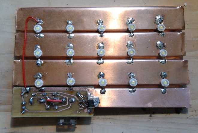
I had spread out the LED s on the copper strips and the
transistor was soldered to a piece of copper as well, but with just
1.15 amps flowing in at 12 or 13 volts - 12 or 13 watts in 15 emitters
(much of which surely comes out as light),
a transistor and a resistor - the whole 4" x 7" works got surprisingly
hot. I think I'll have to use wider copper strips and space the LED s
farther apart. And maybe punch holes in the copper to improve the
airflow. A larger area panel will make shadows more diffuse but it'll
be the same amount of light. This 4" x 7" panel size might be better
with 9 LED s, 675mA, 8-9W. Concerns about simply upping the size are:
(a) While the surface area is the length times the width, the edge
length for
airflow is only the length plus the width (x 2), so airflow doesn't
increase proportionately as the size increases. (One can of course go
for long and thin shape, or thicken the ceiling-to-light gap.) (b) The
copper heatsink sheets are the most expensive component. Larger area
means higher price. But you can't solder the emitters (or anything
else) to aluminum, the cheaper heatsink material.
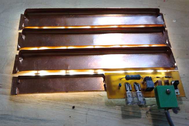
 One further
good thing I noticed on the plus side for the
design as a
whole: Whereas I had been concerned about the unevenness of the light,
with the emitters showing through the diffuser as bright blobs, that
was looking directly at the face. But for a ceiling light,
that
would be standing right underneath it and looking up. Viewed from more typical angles, the bright
spots disappear and a fainter pattern replaces them. At further angles,
a
uniform glow is seen. So for
typical lighting situations, the desired even glow is sufficiently
attained by this layout. I even made the 7x7 box with transparent
sides, since the bulk of the light is aimed downward. That way too, the
light within and its construction can be viewed by potential partners,
supporters and customers - a demo unit.
One further
good thing I noticed on the plus side for the
design as a
whole: Whereas I had been concerned about the unevenness of the light,
with the emitters showing through the diffuser as bright blobs, that
was looking directly at the face. But for a ceiling light,
that
would be standing right underneath it and looking up. Viewed from more typical angles, the bright
spots disappear and a fainter pattern replaces them. At further angles,
a
uniform glow is seen. So for
typical lighting situations, the desired even glow is sufficiently
attained by this layout. I even made the 7x7 box with transparent
sides, since the bulk of the light is aimed downward. That way too, the
light within and its construction can be viewed by potential partners,
supporters and customers - a demo unit.
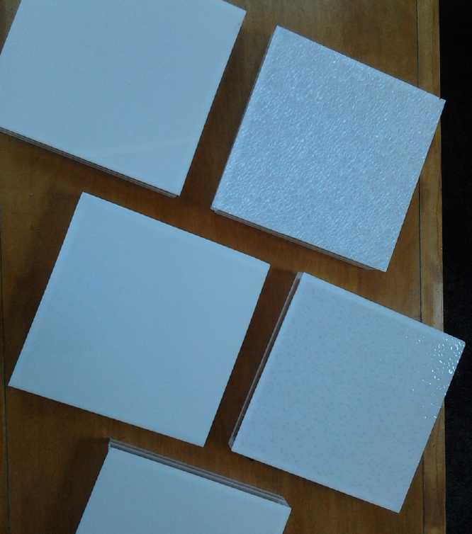
Three of the translucent light cases and the
"cracked ice pattern" ones discussed below.
 On about the 28th I cut enough
plastic pieces to make 5
flat panel LED light cases and assembled them minus the last wall that
holds the light works in place and minus the mounting tabs. It took
about 3 hours. I got better at sawing, finding that one key to
smooth(er) cuts is to not quite cut it through, then snap it off and
sand off the thin bits remaining. I also put masking tape along the
line to be cut, top and bottom. Sharpening the saw blade probably
helped too. But even for home production, I need a way to make it take
less time to cut plastic, not more. The band saw also makes better cuts
than the radial arm saw , even with a coarse toothed band. However, it
doesn't really cut straight lines very well.
On about the 28th I cut enough
plastic pieces to make 5
flat panel LED light cases and assembled them minus the last wall that
holds the light works in place and minus the mounting tabs. It took
about 3 hours. I got better at sawing, finding that one key to
smooth(er) cuts is to not quite cut it through, then snap it off and
sand off the thin bits remaining. I also put masking tape along the
line to be cut, top and bottom. Sharpening the saw blade probably
helped too. But even for home production, I need a way to make it take
less time to cut plastic, not more. The band saw also makes better cuts
than the radial arm saw , even with a coarse toothed band. However, it
doesn't really cut straight lines very well.
On the 30th I did a little shopping looking for a fat
piece of UHMW to make motor molds for the Electric Weel motor and the
Bike Rim motor, but at the plastic shop I found instead some thin,
textured acrylic plastic with a sort of inverse pebbly surface.
(Duralens Cracked Ice Acrylic "22969") It let through more light than
the thin sheet I had bought for the purpose - in fact, I think more
light than anything else 'transulcent' I've seen - and rather than
allowing the sun to show though as a small spot, it broke it into
dozens of tiny points, each of which let through most of the sun's
light.
 So I put
together two more 7x7" lights to see how they'd
compare with the others. One had the texture on the outside face and
the other on the inside. I had the impression it
didn't make much difference. Either way it seemed like a good look and
it seemed to let light through really well. I could see using this on
all sides -- the light would look like a cube of frosty ice! So I cut
edge pieces and glued them over the transparent edges to see the effect.
So I put
together two more 7x7" lights to see how they'd
compare with the others. One had the texture on the outside face and
the other on the inside. I had the impression it
didn't make much difference. Either way it seemed like a good look and
it seemed to let light through really well. I could see using this on
all sides -- the light would look like a cube of frosty ice! So I cut
edge pieces and glued them over the transparent edges to see the effect.
Then, having used the same light workings for all the
tests, I started in on another one on July first. I took the copper
'beams' and punched holes through them for air flow by settings them
over a hole in a piece of wood and then punching them through with a
center punch. This made holes the size of whatever drill bit I used.
This proved quite easy, and contrary to drilling holes, it left them
with jagged copper sides sticking up - extra surface area ideally
placed by the airflow for cooling.
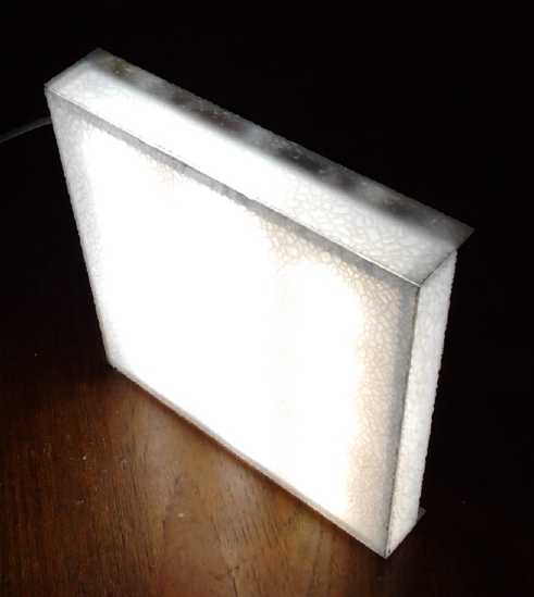
The bright but broken-up pattern of light
through the 'cracked ice' diffuser
Electricity Storage
Turquoise Battery Project
For almost 3 months competing attractions kept me from the
simple test of making a new electrode and battery cell to verify that
the
high levels of self discharge, the last nagging chemical problem of the
whole
Ni-Mn battery chemistry, was
simply due to graphite contaminated with nitrates/nitrites, purchased
at an art supply store. As I hadn't found carbon black so far to buy, I
settled for using the MnO2/carbon black mix from a dry cell. That
leaves the cell with both less carbon black than desired and less KMnO4
than desired, but since it's battery quality ingredients (unless
perchance the KMnO4 isn't pure... egads, another one to check out!), it
should at least work.
On the 29th I finally got to it - I just wasn't going to
let it slip another month! I had worked out a mix in May, the first two
ingredients being the approximate contents of a standard dry cell. But
(without bothering with calculations) there didn't seem to be enough
nickel compared to manganese. Extra nickel doesn't hurt whereas extra
manganese does, so I added 10 grams each more monel and Ni(OH)2, and a
bit more
samarium to account for it, making well over the intended 100g:
28g - MnO2 (or Mn2O3 or MnOOH or Mn3O4 or Mn(OH)2 in various
proportions depending on discharge state)
12g - carbon black (substantially less than I'd like)
18g - KMnO4
28g - Monel
28g - Ni(OH)2
8g - Sm2O3
===
122g
I put in the now usual 40x120mm piece of graphite felt and
shook it all up to impregnate the felt with powder. Then I folded it
into 3 in the 40x40mm compactor box, adding a few drops of Diesel Kleen
and Sunlight dishsoap. I pressed it to 3Mg (mega-grams) AKA 3 metric
tons, in the 20 ton press with gauge, and left it pressing in the press
for a while. Then I torched the surface for a 3-4 seconds, then painted
in a bit of ferric chloride, then matched it with a composite graphite
current collector and wrapped it in watercolor paper.
I looked around for an existing negatrode, but I wasn't
positive which was which now that both 'trodes have graphite composite
current collectors... and anyway it might have become contaminated. I
made a new one, then assembled the cell on the 30th. I used the old
current collectors - not in bad shape - and tossed the electrodes and
their papers and cloths. I put in a little modeling clay around the
slot gaps in the jar so the negode wouldn't discharge from oxygen in
the air getting in.
After a couple of hours charging, I thought that this was
perhaps a bit more like a flooded lead-acid cell than the usual
alkaline dry cell, and wondered if it might benefit from pulse
charging. In mid afternoon I happened across the narrow-pulse pulse
charger I had made some months ago, and (after a little confusion with
the unlabeled connections) hooked it up, with about 6 volts for power
and for charge voltage. I put in a 10 ohm resistor to limit charge
current.
Testing
Voltage came up slowly from under 1/2 a volt as it usually
does, stopping for quite a while at 1.6 to 1.8 volts ("Ni-Zn") while
the zinc powder turned or returned from oxide to metallic form. When
the pulse charger was put on, the reading jumped up to 2.4 volts, but
that must have been peak voltages, or at least above the average DC
level... I think.
Later I found it hadn't charged above 1.9 volts - not an
auspicious sign! In fact, it just didn't want to charge higher. That
sounded like a negative electrode problem, not the plus side. Kind of
like 2012 before the zirconium silicate, when it worked in winter but
not in summer. I put some water in a container and put the battery in
it, then I put in some ice cubes. Gradually the voltage started to
rise. But the ice melted and it was bedtime. The container had
indicated the mix had the right things, but obviously there was some
problem with it.
The next morning, July first, I put in a slice of zinc as
a test electrode. This verified that the voltage from the negode was
about the same as the zinc, the cell voltage being a little over 1.8
volts with either. The manganese wasn't charging. I disconnected the
pulse charger, oscilloscope et al and put the cell in the fridge.
Self Discharge Appears to be Solved!
After the charge had been turned off for a couple of hours
it also looked like there was less self discharge from the posode. I
used the zinc strip to check it against, and I pulled the strip out of
the cell after each test, to prevent cumulative effects emanating from
the minus side. I decided to leave it sitting a day or more and get a
clearer picture. Voltage was 1.76 and it would supply 150mA into the
meter shorted on the 0-300mA scale. After 12 hours voltage was 1.707
and it supplied 145mA, and these figures stayed steady another 3 hours
until I went to bed. The next morning (24 hours) it had about the same
voltage - even up a bit (<= 1.712v) after I wiped the zinc with a
nylon pad. The current drive had dropped to 134-139mA depending on
placement of the zinc. (Using two zinc strips didn't raise it much.
Say, wasn't the electrode compaction supposed to be much stronger?
Where did I get the low values I used this time?) 36 hours: 1.698v,
129mA. 48 hours: 1.690v, 128mA.
Like most if not all rechargeable cells, Ni-whatever
cells do have some self discharge. Especially over the first day they
may lose 10%. The drop with time here is within that sort of range and
quite workable for EV use. The
essential high self discharge problem, which had been leaving the cells
with dropping voltage and little usable energy after a day or so,
seems to be solved.
It would seem the art store graphite powder, probably
impure with nitrates, was indeed the
problem all along. I *think* all problems with Ni-Mn flooded cell
battery chemistry are now solved. Remaining problems are production
problems, especially getting things to stay sealed.
But now, I still
don't have a properly working cell because of the unexpected problem
with the negode! The manganese won't charge even in the fridge, and
even the zinc discharges itself over some hours.
That's surely just some glitch - nickel-zinc is known to work, and
manganese certainly was holding charge previously. (Maybe even from not
compacting it enough?) I'll mix new chemicals and make another one in
the coming days.
http://www.TurquoiseEnergy.com
Victoria BC