Turquoise
Energy Ltd. News #78
July 2014 (posted August 3rd)
Victoria BC
by Craig Carmichael
www.TurquoiseEnergy.com
= www.ElectricCaik.com
= www.ElectricHubcap.com
= www.ElectricWeel.com
Features: Ni-Mn 2-1/2 volt
battery self discharge reduction (see month in brief, Turquoise
Battery project)
Month In Brief
(Project Summaries)
- Flat Panel LED Lighting - Electric Weel Motor/Generator -
Battery Renewal - Car Transmission - EV Individual Battery Monitor
- NiMn Battery Development - NiNi Battery Idea - Electric Caik
Outboard boat trip -
3D Printer repaired.
In Passing
(Miscellaneous
topics, editorial comments & opinionated rants)
- Illustration: "Price of electricity versus gasoline"
- A planeload of people killed to eliminate free energy?
- Slight of Hand: Repeated Insinuations Batter the Brain to
Manipulate Perception
Electric Transport - Electric
Hubcap Motor Systems
* Electric Weel Motor/Generator - Plastic for Molds: at long last, the
project proceeds
* Individual Battery Monitor - El Cheapo version (7-segment voltage
displays)
Other "Green"
Electric Equipment Projects
* Flat Panel LED lights: - assembly, circuit boards...
Electricity Generating (no reports)
Electricity Storage - Turquoise
(NiMn) Battery Project etc.
* Reducing or eliminating the NiMn self discharge
* Lead-acid battery renewal - Learning more chemistry - lower voltages
with higher pH.
No Project Reports on:
Variable torque converter transmission, Peltier heat pumping, Lambda
Ray Collector, Magnet motor, CNC
Gardening/Farming Machine (sigh, maybe summer...
2015?),
Woodstove/Thermal Electricity Generator,
evacuated tube heat radiators.
Newsletters Index/Highlights: http://www.TurquoiseEnergy.com/news/index.html
Construction Manuals and information:
- Electric Hubcap Family Motors - Turquoise Motor Controllers -
Ersatz 'powder coating' home process for
protecting/painting metal
- Preliminary Ni-Mn Battery Making book
Products Catalog:
- Electric Hubcap 4.6KW BLDC Pancake Motor Kit
- Electric
Caik
3KW BLDC Pancake Motor Kit
- NiMH Handy Battery Sticks, 12v battery trays & Dry
Cells (cheapest NiMH
prices in Victoria BC)
- LED Light Fixtures
(Will accept BITCOIN digital currency)
...all at: http://www.TurquoiseEnergy.com/
(orders: e-mail craig@saers.com)
July in Brief
I took things more or less
a work session at a time in the
first half of July, trying to do less "multitaskings" and more "in the
present moment" concentrated efforts, and to prioritize in advance
and not let the most important or timely projects lapse without
progressing. After that I was doing Weel motor pieces, monitoring
battery performance, and miscellaneous project work. It was quite a
productive month.
Flat Panel LED Light
Over several
mornings I put together an improved flat
panel LED light - the inner workings - with an improved circuit board,
higher light output from 12 watts with twenty 2.9 volt LED emitters
driven more
softly: less heat, and better heat dissipation. But it gave full output
above 13 volts. I hope I can bring that down some. OTOH, it's a good
battery saving voltage for off-grid use, dimming more and more as the
batteries get lower.
I found it was simple
to
punch vent holes in the copper strips with a center punch, a piece of
wood with a hole for the punch, and a hammer. This was better than
drilling the holes because jagged sides were left around the holes as
"cooling fins". Then I got onto other things.
At the end of the
month a couple of the 1200 lumen Chinese LED 'light bulbs' quit within
a day of each other (one for the third time), suggesting that replacing
them with my own lights instead of just repairing them might be
worthwhile. That'd also be good real-life testing before trying to
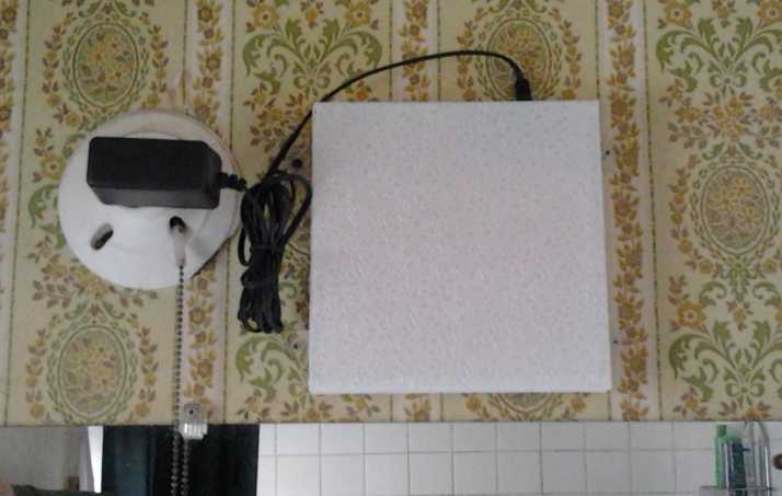
market them. On the morning of August 1st I mounted the aforementioned
light in
the bathroom above the mirror. It was nice to be able to reposition the
light
away from where the window hits the bulb when it's swung open.
 It's okay with the 12 volt power
adapter, but it could have been brighter... about that 13 volts! (And
about that wire...)
It's okay with the 12 volt power
adapter, but it could have been brighter... about that 13 volts! (And
about that wire...)
Electric Weel Motor
 Fortuitously
getting some very suitable UHMW-PE plastic from
Jim Harrington at AGO on the 5th, I made a mold for 1/8 circle pie
sections for
the giant
Electric Weel motor and generator, a long dormant project that I've
been wanting to get on with. Then I cast
a pie piece with it.
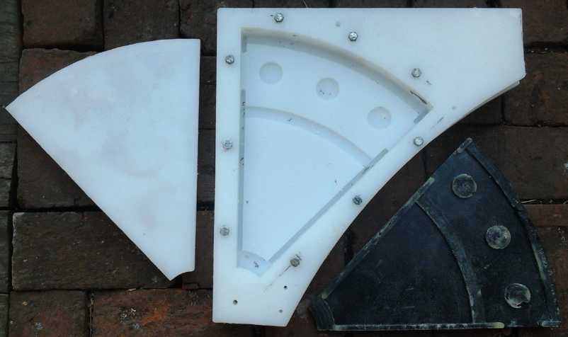
This was a 3-piece mold to get sufficient depth for some side wall
'ribs'.
The piece looked great, but the coil "buttons" turned out too large and
the toroid coil cores wouldn't quite fit over them. I went back over
the G-code for previous motors and found I had made them 10 thou
smaller than the stated 1.250" dimension (1.240") to ensure they'd fit.
Recalling they were a very tight fit even at that, I changed the Weel's
coil button program to make them 14 thou smaller (1.236") and routered
out a new mold piece. Over 10 days
or so ending about the 24th, I cast the remaining 7 sections and had
the full circle, and I also designed and routered a couple of sections
of the next mold. I
haven't epoxied it together into a single unit yet.
Fortuitously
getting some very suitable UHMW-PE plastic from
Jim Harrington at AGO on the 5th, I made a mold for 1/8 circle pie
sections for
the giant
Electric Weel motor and generator, a long dormant project that I've
been wanting to get on with. Then I cast
a pie piece with it.
This was a 3-piece mold to get sufficient depth for some side wall
'ribs'.
The piece looked great, but the coil "buttons" turned out too large and
the toroid coil cores wouldn't quite fit over them. I went back over
the G-code for previous motors and found I had made them 10 thou
smaller than the stated 1.250" dimension (1.240") to ensure they'd fit.
Recalling they were a very tight fit even at that, I changed the Weel's
coil button program to make them 14 thou smaller (1.236") and routered
out a new mold piece. Over 10 days
or so ending about the 24th, I cast the remaining 7 sections and had
the full circle, and I also designed and routered a couple of sections
of the next mold. I
haven't epoxied it together into a single unit yet.
Once this motor is done, I have an idea how to beef up my
motor controllers to get them working reliably even at very high
currents. (I had to admit that my
controller would
probably have blown up to a potential customer.) If that's successful
I'll have
really excellent sets of controllers with three sizes of fabulous
motors.
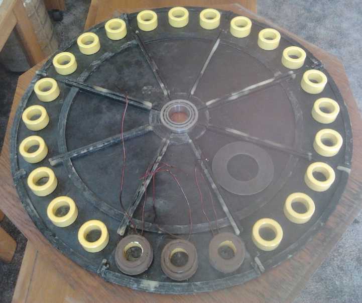 Electric Weel Motor - stator end, ready to epoxy together
Some coils, coil cores, and a shaft bearing are shown.
Battery Renewal
 Finding another deteriorating
battery in the Mazda RX7-EV, I decided it was time to try again
to renew a lead-acid battery, of which I have a number sitting around -
mostly out of the Mazda. This time, I had learned that an important
number I had been using on a chart was in error - way off - and this
had led me astray for years in what I had assumed was happening inside
the cells.
Finding another deteriorating
battery in the Mazda RX7-EV, I decided it was time to try again
to renew a lead-acid battery, of which I have a number sitting around -
mostly out of the Mazda. This time, I had learned that an important
number I had been using on a chart was in error - way off - and this
had led me astray for years in what I had assumed was happening inside
the cells.
Now comprehension began to dawn that the lower voltages I
was so often getting were due not to "shorted cells" in the battery,
but rather to decreased acidity as more neutral sodium sulfate -
perhaps far too much - was added. My renewal "failures" were probably
just failure to understand.
I put the renewed battery into the Mazda. It reliably
provided 5-7 volts for extended periods of driving. It seemed to react
slowly to high loads, dropping in voltage and then rising over a few
seconds while the current stayed the same.
I should probably reduce the concentration of Na2SO4 in
all the batteries I've done and still have, and then maybe add some
acid to them if they still won't hold a good charge.
Car Transmission
I opened the manual transmission I bought for the Chevy
Sprint to see what went into it, but got no farther putting the Sprint
together. There were some very interesting gear arrangements, which are
probably pretty standard. One shaft turned a second shaft which
(depending on the gear selected) turned a third shaft which drove the
differential, and both the input and output shaft had gears turning
both directions at the same time, all churning up the heavy gear oil.
The reasons a typical manual transmission is said to lose 30% of the
input energy started adding up. Each individual meshing gear only had
to lose a few percent when there were so many of them engaged at once.
(Automatics and 4-wheel drives are worse - 40%. Hence my lengthy quest
for something better. Couldn't they at least make them with 99%
efficient flat belts instead of metal gears in heavy oil? But cars are
designed from start to finish to consume fuel - the car companies work
with the oil companies, all under the gangsters who've been running our
society so far.)
Electric Car Individual Battery Monitor
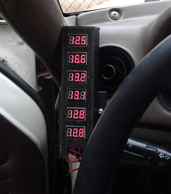 On the 12th I
made a sort of plastic case and put in 6 of
the little 4-LED-digit voltmeters - the "el-cheapo" version of the
individual battery monitor for EV s. The next day I finished getting it
into the Mazda showing the five batteries under the hood and just one
(any one) of the six rear under-trunk batteries.
On the 12th I
made a sort of plastic case and put in 6 of
the little 4-LED-digit voltmeters - the "el-cheapo" version of the
individual battery monitor for EV s. The next day I finished getting it
into the Mazda showing the five batteries under the hood and just one
(any one) of the six rear under-trunk batteries.
The process got exciting when I accidentally touched a
wrench to Ni-MH terminals with 24 volts between them to attach a
connector. It welded itself on for a few seconds, but I managed
to knock it off. The wrench "fingers" that grip the nut were gone, and
a hole was burned into the center of the wrench. Not to mention that
those two nuts will never be turned again. The batteries still seemed
to be pretty fully charged.
The displays showed that some batteries were being charged
to slightly higher voltages than others: 13.7, 13.8 or 13.9. (The
lithium-ion battery was at 18.7.) Optimum for the Ni-MH s should be
14.0
but no more, and they weren't reaching it.
The first drive showed that the lower 90 AH Ni-MH battery
wasn't performing as well as the upper one, dropping substantially more
voltage under heavy loads. I'd suspected that but wasn't sure. This was
an immediate vindication of doing individual battery monitoring. It
also showed that the lead-acid batteries had lower load voltages than
the Ni-MH s, from the start dipping under 12 volts with load when the
Ni-MH s were dipping under 13 volts. So the PbPb s were yielding maybe
5-9% less energy with the same nominal ratings.
Either the lower Ni-MH battery needed looking at or it
just wasn't being charged as high. I may re-make them both as soldered
battery
"packs", as I'm becoming increasingly mistrustful of the bulky "giant
flashlight tube" or "battery stick" batteries where there are more than
maybe 2 or 3 or 4 tubes. It's hard to tell in a permanent installation
if there's a
malfunctioning tube and then hard to pin down which one it is.
In addition the weakest 'size 27' lead-acid battery in the
back was shown to be weaker than the two 'size 24's in the front (both
pretty fair despite being rather small for an EV), dropping more
voltage with load and as the trip progressed. It soon needed
replacing -- but I could see its voltage drop and removed it before I
started running it into the ground. It should be good to renew.
With the monitor showing the weak links, I can work on
improving them and hopefully getting more range out of the car. Of
course, it could use a second monitor to show all the rear batteries at
once. (Ugh!) Since getting a look at all those numbers on the first
monitor is distracting while driving, perhaps this should be an
incentive to do the "real" monitor with programmable green bar graphs
for each battery that turn yellow as it gets low, red when it's really
time to stop, and flashing red if they're probably sustaining damage
under load.
NiMn Batteries
The main focus of the month's Turquoise Battery Project
was to try to eliminate, or reduce to practical levels, the self
discharge that has been plaguing the cells. Such a project involves a
little wok and then oodles of charging, cycling and testing. There was
some success, but it's not clear yet whether the steps taken will be
sufficient, as the cells evidently need a lot more cycling to prove or
disprove the efficacy of the effects.
On the 14th I made a new 'negode' without graphite felt,
after the one last month with felt wouldn't charge. Sure enough, the
felt mustn't have had enough hydrogen overvoltage and was gassing,
because this negode worked.
I thought eliminating "contaminated graphite powder" from
the positive electrode would finally end the nagging high
self-discharge problem. But nothing changed from earlier cells. A zinc
strip test electrode revealed that it was the negative electrode that
was 'leaking'. Somewhere months back I had determined it was the
positive, but obviously that was wrong. It was already fine and nothing
I did to it would help.
Charging a cell for a week or more with sufficiently high
charging current to keep the charge voltage around 2.9 volts, gradually
brought the self discharge down, but acceptable levels weren't attained.
So I made another 'negode', this time with about 11%
zirconium silicate additive instead of the 3% I'd been using. After
just one night's charge, its self discharge was just 1/2 as fast as the
best figure with the previous electrode - 26 seconds per millivolt drop
instead of 13. But it didn't improve with time.
I decided to try something organic. I took the cell apart
again and painted both electrodes with "Diesel Kleen", which contains
tri-methyl benzene (among other things) and doesn't evaporate rapidly
like straight methyl benzene (toluene). This time the cell started
improving with charging and after a couple of days it became
impractical to stand there ticking off seconds - 45 to 70 - waiting for
the meter to drop by one millivolt. Success? But it still didn't
progress to an acceptable level, and then it seemed to regress a bit.
After a load test August 1st it improved a little again. Looks like it
needs cycling, not just charging. I'll be running more tests in August,
and I might add more "methyl-something" if it seems necessary.
AFAIK for the first time ever, a manganese negative has
been induced to charge and to hold manganese's high voltage metallic
charge... at least for a while. I thought I had an earlier cell headed
for success of some weeks, but its zinc current collector corroded away
before proving it. This time I think I have a better idea of what's
helping. If the high self discharge can be adequately solved, it'll be
the highest theoretical energy density ever likely to be attained in a
water based electrode and battery, by a good margin.
NiNi Batteries
At the end of the month I decided to include some of these
in my next 'batch' of batteries. They would be under 1/2 the voltage of
the NiMn cells, about 1.1 volts nominal, actually charging to 1.25 or
so. There are two or three reasons for making them.
First of course is that I haven't necessarily solved the
self discharge problem of NiMn. It looks promising, but in spite of the
major advances already obtained it's possible that I never will, or
even that it's impossible entirely. The lower voltage NiNi cells should
have little or no self discharge. Second is that the lower voltage of
NiNi should allow it to be made as a sealed dry cell - I doubt NiMn dry
cells would be practical. Third is that except for being .1 volt lower
(and hence needing 11 cells for 12 volts instead of 10), they should
actually be better in some ways (with 'everlasting' cycle life) than
nickel-metal hydride, of which larger size production has so far been
suppressed by the corrupt, and also should be the most readily makeable
at home or in small production of any battery.
Boat Trip with Electric Caik Outboard
On the 30th, after preparations (some going back some
weeks), I finally took my 14' aluminum boat with the Electric Caik
outboard out on a fishing trip. There was a breeze and some distant
whitecaps
could be seen, but it wasn't that bad where I was. The waves still made
me
seasick, but
weren't splashing over the sides. After 20 minutes or so I reeled in
the
line and went back in (no fish). My Chinese voltage and current
meter with 50 amp shunt did fine on voltage, but the current readings
bounced around
wildly. Evidently it can't handle pulsed circuits. The Electric Caik
motor RPM with a 16 volt lithium battery
never got over about
1700, so there was no chance of accidentally over-revving (unless it
ran out of charge and I had to switch to the 24 volt NiMH.)
I didn't measure the motor temperature, but I took the
hood off as soon as I got back. After this considerable run, the motor
still felt cool... except that the heads of the coil holding bolts
were hot (not finger burning, but getting up there). They are of course
heated by magnetic induction from the magnet rotor... oh yah, and from
the magnetic switching of the coils. I had reduced the
bolts from 1/4" to #10 to pick up less magnetism, but it seems they
still get hot. I think I want to find a way to make motors with even
less - ideally no - 'extra' metal bits in the path of the rotor.
Plastic clips?
I started thinking of putting the coil clamping bolts
for the Electric Weel inside and outside where the magnets
pass, but having none in line with them. (And definitely outside the
coil cores!) Originally the bolts held the
coils in place as well as clamping them, but with the coil holding
buttons molded in, the bolts
don't have to be inside there any more, just somewhere to clamp the
body
pieces together. I can probably change the bolt configuration template
on the Hubcap and Caik motors too, tho there's little room in the Caik
to really get them clear of the magnet fields.
3D Printer: Repaired
To end up a rather successful and progressive month, I
ordered and received a new "Melzi" circuit board from RepRapPro, and in
the evening
after the fishing trip I installed it in the 3D printer, adjusted
things,
and successfully
printed out a trinket. Yay! The printer had been offline for almost 14
months and I really need it to make some things - more CAT plugs and
sockets, and I want to try making frames for electrodes for the NiMn
2.5 volt (and NiNi 1.1 volt) salty electrolyte cells, to keep the paper
edges from bursting
open and leaking briquette substance.
In Passing
(Miscellaneous topics, editorial comments & opinionated rants)
The price of electricity to run a car
Someone made this picture up to illustrate how much less
it costs to run an electric car than a gas one. I think it was at
11¢/KWH. Sure beats a dollar and a half per litre!
A planeload of people killed to eliminate free energy?
Someone has told me that the Malaysian passenger jet that
famously disappeared over the ocean 3 or 4 months ago had a team of
people on board
that had created a "free energy" device -- likely a
'lambda ray
collector' (TE News #69,70,71). Perhaps they were in southeast Asia
looking for
manufacturing arrangements.
This is just a rumor as far as I know, but it certainly
would be a convenient way to dispose of a whole team, the inventor
and all involved, if they were all on the same flight, without raising
immediate suspicion that getting rid of yet another free energy
invention was the motive. And it's a very good explanation for why the
plane would have crashed without even a distress call or a signal from
the 'black box'. It was probably blown up with a bomb or otherwise
booby-trapped so that no one would get off a distress call. The crew
and the rest of the passengers were then just 'incidental' casualties
-- and cover to obscure the motive. Who would suspect?... but I've
heard before of airliners apparently being downed to kill just one key
person on board.
The perpetrators of this crime against humanity - if
indeed that's what it was - may be "rich" and "powerful" and able to
elude human
justice, and laugh it off or even brag about it in their inner circles,
but they will still have to answer for it on high when their mortal
days have ended. When they come face to face with the universe
outworkings of what they have done, they may well condemn themselves
for the lives they have lived and their evil deeds.
They are cunning and ruthless, but even in the material
sense they are blind fools.
They want to prevent progress, seemingly taking some sort of
satisfaction in ruining
the beautiful planet they live on, and without stopping to think that
the reason they aren't running around barefoot and hunting
deer with sticks and rocks is because of the sort of inventive people
they work so desperately to put out of action.
As for the newer Malaysian jet disaster, the one shot down
over the Ukraine... the airline and the crew were certainly playing the
odds, flying through a war zone in an airspace where multiple aircraft,
albeit military, had been shot down on previous days. The issue had
come up, and some airlines were re-routing their flights. Others didn't
want to pay for extra fuel and time.
As for who fired the fatal missile: Western Ukraine,
Eastern Ukraine, and Russia all have the same missiles. Russia
has been trying its best to stay out of the conflict - except to accept
the stream of refugees coming across the border. Considering Western
Ukraine has been raining destruction on Eastern with aircraft and that
Easterners have naturally been shooting back at the aircraft, the Kiev
government is by no means blameless, regardless of who fired the
actual shot.
Slight of Hand: Repeated Insinuations Batter the Brain to Manipulate
Perception
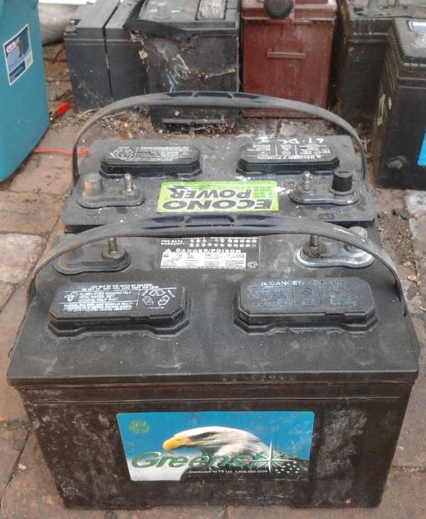 One of those
lead-acid batteries I was renewing has a
large sticker with the head of a sharp-eyed eagle and the word
"Greens". Another
nearby had a green sticker saying "Econo Power". What's not to like
about "green", "econo" and "power"? And what could be
closer to nature, be more powerful, and see things more clearly, than
an eagle? But the labels make no actual claims to
denounce. They are tools in a subtle form of
decept also carried out via other means such as mainstream media.
One of those
lead-acid batteries I was renewing has a
large sticker with the head of a sharp-eyed eagle and the word
"Greens". Another
nearby had a green sticker saying "Econo Power". What's not to like
about "green", "econo" and "power"? And what could be
closer to nature, be more powerful, and see things more clearly, than
an eagle? But the labels make no actual claims to
denounce. They are tools in a subtle form of
decept also carried out via other means such as mainstream media.
With the repeated misleading association of such positive
terms and
icons with perhaps the most negative common battery type - the least
green, least economical [over time,
and without battery renewal], and with almost the lowest power
for its weight - a perhaps subconscious association is formed in the
mind between these opposites, and one gains by osmosis the impression
that lead-acid is "seen clearly" as a
green, economical and powerful battery type. At the same time,
derogatory remarks about other battery technologies by those making a
good living off short-life lead-acids, and probably by paid shills and
spokesmen, blow up molehills
of near trivial weaknesses into mountains of seemingly expert
criticisms of other chemistries. And
still further, the corrupt have shut down nickel-iron and large cell
nickel-metal hydride production entirely in the west, with the
molehills and other misleading propaganda as excuses for why, to soothe
the public and deflect popular outrage. The fact that these types are
unavailable and it appears no one uses them seems again to support such
assertions by osmosis, since the obvious logical conclusion, especially
by the young and innocent who naturally assume that fair play rules in
our world,
is that if other types were better they'd be produced and in common
use. The news
repeatedly has stories about exciting new battery developments... which
never seem to get onto store shelves. Lithiums are tolerated because
the demand
for better batteries is too high to quell, yet their high cost chills
the mass market while at the same time diverting attention and
inventive and economic
energy from other better types.
Whenever someone makes a decision regarding batteries, all
the misleading associations and misrepresentations, presented
repeatedly whenever and wherever
the subject arises, are in the subconscious, working to cloud impartial
judgment. Yah, green, economical and powerful lead-acid is the only way
to go!
And this same technique is used in many areas. The USA is
trying to pick a fight with Russia. It's managed to get Poland to
accept placements of its ludicrous "anti missile shield" installations.
It's spent billions of dollars to destabilize the Ukraine, in order
dominate it economically, and to move in and up to Russia's border.
Everything that's happening there is being repeatedly blamed by US
politicians and their spokesmen
on "Russian aggression" with no evidence (even when asked to present
it) that Russia has done anything aggressive. Indeed, Putin has been
most restrained in his responses, to the point where author and former
assistant treasury secretary Dr. Paul Craig Roberts
[PaulCraigRoberts.org] thinks leaving Russians in the Eastern Ukraine
(historically part of Russia) to the mercy of the attacks by the Kiev
government is going to backfire on him. And yet, surveys show that the
majority of people in the USA believe Russia is to blame for what's
happening - Surely those ongoing claims, repeated and repeated in the
news with
apparent conviction, must be backed by facts, not just hot air? Some
haven't learned from Iraq and Saddam Hussein's non-existent "weapons of
mass destruction" that the aggression is coming from their side, that
it's all lies and the USA has become the USSR, or as some put it, the
"USSA". (Joke losing funniness... Q: How do you know a politician is
lying? A: His mouth is open.)
Shortly after writing this, I ran across an hour long
youtube video lecture, Propaganda and Manipulation: How Mass Media
Engineers and Distorts Our Perceptions. It goes into the insidious
techniques mentioned and others, and examines the often
devastating results.
Perhaps I should repeat my own bit of 'propaganda' to set
the message into the subconscious of anyone with any influence who may
chance to read these words:
No More Wars!
Don't start them, don't provoke them, don't join in them. No foreign
military power is going to invade North America and we have no
legitimate reasons to be trying to dominate and control nations abroad
- much less to be invading and killing people and turning whole
societies and
peoples into chaotic messes with many millions of refugees who have
nothing to eat and nowhere to go. Violence begets violence. And I must
include Canada in this, since our government of late has been showing
all the signs of being led by the same bankster-gangster methods and
motives as the US government.
We've known
for decades that if wars continue, they'll sooner or later escalate
beyond one-sided massacres, and probably destroy all life on our
planet. As it is, they're definitely contributing to and speeding up
the coming global financial, economic and population collapse.
No More Wars!
No More Wars!
No More Wars!
Electric
Hubcap Motor Systems - Electric Transport
Huge Torque, Low
RPM Electric Weel Motor-Generator Project
Resumed at last!
On the 5th I showed the LED
light to friends. I happened to mention I had found the "cracked ice"
diffuser plastic while looking for some big "offcut" chunks of UHMW-PE ("ultra-high molecular weight polyethylene")
to make motor molds with. I was told there were some big scrap pieces
of UHMW under the stairs at AGO, and we went there. I picked up just
what I needed, and there's more if I need it. This was great since it
would have cost me hundreds of dollars for just enough UHMW at
Industrial Plastics. (One problem is that I needed about 14"x14" and
IP will only sell in multiples of 12", ie, a 24"x24" piece, to get it.)
As it was, the
pieces were the oversize outside corners
left over from cutting very large rotors - about 16x16" with a huge
quarter circle bite out of one corner leaving only 4" sides on each
side of the bite. The plan was to make a 1/8 of a circle (or octagon)
mold, and mold 8 identical "pie" pieces that would form the complete
octagon or circle for each motor. I thought these plastic pieces would
be too small for the largest mold sets, but after a couple of hours of
drawing on one with a felt pen (and erasing with alcohol), attempting
to design a good pattern for the outer stator end ring, as well as to
hopefully fit it on the plastic, I found I could lay out a very good
one, with ample outside margins, by skewing it at 22.5° so the
"pie" slice lined up with one edge. In fact the size and shape of the
plastic pieces was almost ideal for the mold. This got the long-stalled
Electric Weel motor project back in motion at last.
Whereas all my previous molds have a one piece "dish" on
the bottom to make a flat ring, this motor is so big I wanted to put
some fairly tall radial ribs ("spokes") in it to stiffen it up - even
5/8" or 3/4" tall. My biggest concern about this motor is the stiffness
required to hold the axle and hence the magnet rotor, when the bearing
is at the center and the magnets are so far away at the outer rim. Just
a little flexing of the outer cover and the magnets will start rubbing
on the inner stator wall - which they pull toward magnetically. The
UHMW plastic is just under 7/8" thick, so to have such ribs sticking up
above the rest, meant bolting two pieces together to get a deep enough
mold. And if I put the ribs at the edge of each octagonal slice,
they'd provide the maximum thickness of edges to epoxy (and perhaps
screw or bolt) the 8 pieces together into a complete circle with.
I figured bolting two thicknesses of UHMW together for the
deep dish - and then prying them apart when the casting has set - would
make removing the castings much easier than with a very thick single
piece mold. (It was still surprisingly hard to pry the pieces apart,
and I finally started waxing the mold before casting.)
The next step was to set up a G-code program for the CNC
drill router to cut it. I did this, and then cut the two 'dish' pieces,
on the 6th, finishing rather late in the evening. The top cover piece
followed on the 8th. Offsetting the radial lines and circumferential
curves by the radius of the router bit made for some tricky
trigonometry for all this, since it slightly changed all the angles and
cut lengths, and made inner angles different from outer.
Fortunately, even slight errors made the cut lines look
noticeably "off" on the CNC program display, and all errors got
corrected (or got approximated closely enough), except that the inner
diameter edge didn't seem quite right. Luckily it's a short segment,
and it overlapped the top cover rather than leaving a gap. I filed and
scraped it out a little to get it to fit. (Later I found I had entered
co-ordinate "1.354", as "1.345".)
On the 9th I looked over back issues of TE News (like
maybe #38 to #42) to decide how much epoxy resin and polypropylene
cloth to use. It's been so long since I made a motor I didn't remember.
It seems I eventually picked about a 4 to 1 ratio of epoxy to cloth by
weight, and maybe 500g of epoxy and 125g of cloth would be a good
amount to use. 8 pieces will then be 5 Kg for the stator end cover.
That's very light for such a huge motor. If it's stiff enough. The
whole motor, with so many heavy coils and magnets, a huge metal rotor
plate and a fat axle and bearings, will of course be heavy, but this is
about the lightest possible composite body material, and it'll probably
be very easy to manage compared to other motors of such power. And one
suspects, 'amazingly' light compared with other motors of similar
torque.
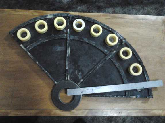
First 3 pieces of 28"
diameter Electric Weel ! Ruler is 16" long.
 On the 10th I put nine threaded
bolt holes around the
edges to hold the two bottom "dish" pieces of the mold together, and
cut strips of polypropylene cloth to make four 125 gram bags of strips.
On the 11th I tore a bag of the polypropylene strips into 6" x 6"
squares,
mixed 500 grams
of epoxy, and stuffed the mold, using the "kneading" technique with
vinyl gloves on to mix the fabric and epoxy. It turned out well enough
- slightly bulged in the center, and with a little missing cloth and
epoxy in spots in the tight corners. The first one came out easily
enough by
unbolting the lower mold pieces and prying them apart, with some more
prying on the part itself. (Subsequent ones got harder to remove, until
started I waxing the mold.) The 625 grams of composite material seemed
about right.
On the 10th I put nine threaded
bolt holes around the
edges to hold the two bottom "dish" pieces of the mold together, and
cut strips of polypropylene cloth to make four 125 gram bags of strips.
On the 11th I tore a bag of the polypropylene strips into 6" x 6"
squares,
mixed 500 grams
of epoxy, and stuffed the mold, using the "kneading" technique with
vinyl gloves on to mix the fabric and epoxy. It turned out well enough
- slightly bulged in the center, and with a little missing cloth and
epoxy in spots in the tight corners. The first one came out easily
enough by
unbolting the lower mold pieces and prying them apart, with some more
prying on the part itself. (Subsequent ones got harder to remove, until
started I waxing the mold.) The 625 grams of composite material seemed
about right.
But the next day I tried fitting a coil core over the
buttons. It just wouldn't go. Either I had made the previous motor coil
buttons a few thou undersized to fit well, I had a number slightly
large on this one... or the radius of the router bit was actually
slightly over .125". The diameter measured .252" with a micrometer, or
.126" radius. That didn't seem like enough to account for the problem -
it might even be measurement error.
That put a slight monkey wrench in the works. Instead
of casting more pieces of the motor and moving on to the next mold, a
revised section was needed for this mold. I did that on the 15th or
16th, and had a half circle on the 18th.
On the 18th I also designed and routered the first piece
for the mid-ring mold, the separator between the coils and the rotor,
and the 2nd piece on the 19th. This would again be in 8 segments.
I trimmed the button edges on the first piece with a
'dremmel' tool with a steel cutting bit with straight sides and a
square end that also cuts. This technique worked very well and I must
remember it for whatever future PP-epoxy trimmings are required.
Talking with a friend on about the 17th, the idea came up
to build up the outside face of the motor, noting that the pieces that
weren't uniform thickness, with more epoxy and PP cloth in the thinner
spots. Then, even better, to epoxy some PP strapping along the joins to
attach the pieces together, along with simply gluing the seams with
epoxy. That should make very strong joins and my confidence in the
robustness of the design has risen. In fact, I changed 500g epoxy +
125g shredded PP cloth per piece to 400g and 100, which makes thinner
pieces, but is easier to stuff into the mold.
I finished the last of the 8 pieces on the evening of the
25th. But I didn't get them glued together.
Electric Weel Stator End Pieces
Eight 45° "pie" pieces with toroid coil mounting 'buttons'
showing 3 finished coils and 21 unwound coil cores,
1.75" 'trailer' tapered roller bearing, and one
of the washers to clamp the bearings with.
With 24 flat molded pieces plus a huge rim to make, this
isn't
going to be a cheap motor/generator to produce. On top of all the
mechanical and electromagnetic parts, the molded body is a huge amount
of
work, and I can see 300 or 400$ of epoxy and PP cloth going into each
one. It'll weigh quite a lot, but the design and composite body will
surely make it much lighter than any similar sort of motor, and the
efficiency should be excellent.
EV Individual Battery Monitor - El Cheapo version (7-segment
voltage displays)
(Batteries top to bottom:
a size 27 lead-acid (rear), 5 cell lithium-ion, two NiMh
90 AH D cell tubes, and two size 24 lead-acid, that
seem here to be more charged than the rest.)
On the 12th I opened the
drawer with the little 7-segment display
voltmeters (a very few dollars each from China, found somewhere on
aliexpress.com), and decided it was high time to make at least the "El
Cheapo" individual battery monitor. I got out some ABS plastic and
methylene chloride solvent to 'glue' it with, and made a case of
sorts that I could screw in 6 little displays in a vertical column.
Then I found an 8-wire cable, poked another hole in the rubber gland
with the main hood-to-dash wiring, and pushed it through.
I didn't like hard-soldering the wire to the displays in
the case, but it was a lot easier than finding plugs and sockets to do
it, especially on the weekend with the electronics store closed and
with the 3D printer still off-line, so I could neither buy nor make
them. (I finally ordered a new "Melzi" control circuit board from
ReprapPro for the 3D printer. Their techs said from the sound of it,
the cheap Chinese board I got was a "version 1" and it looked like it
had a common version 1 hardware problem - that the temperatures would
never read
right. They apparently came out with a beefier "version 2" board a
while back.)
And I soldered CAT click-lock plugs (still have a few!)
onto the other end of the wire to match the sockets placed on every
second battery when I put them in the car. Unfortunately they were on
the wrong every second battery in the front of the car (#2 & #4),
and instead of being able to see all 5 batteries, I just hooked up 3
(#2, #3, #4) via two plugs: one of the smaller "size 24" lead-acids,
and the two 90 AH D cell Ni-MH long tube batteries.
The first thing notable was that there's no way to turn
the displays off except to unplug them all. I don't suppose they'd
discharge the batteries in any length of time that might be a concern.
Also of note is that the red LED displays can't be read in sunlight,
but are overly bright at night. An LCD display would be better.
I put the display up pretty high on the left side of the
dash where I thought it would be easily visible. Instead from driving
position it was perfectly covered by my left hand on the steering
wheel. I had to shift to the right to see any of the displays. Awkward
to see equals easy to be unduly distracted and have an accident.
(I totalled a nice car and injured myself badly that way once, with a
poorly functioning add-on intermittent windshield wiper control,
mounted too low down.) Nevertheless I went for a 4.2 mile round trip
drive, with Tillicum mall
at the
far end. I then moved it to the far left. That was better, but really
the
only place easy to see is where the factory instruments are, behind the
middle of the steering wheel.
Even displaying 3 batteries was rather revealing. When I
started out, the size 24 lead-acid quickly dropped below 12 volts. The
Ni-MH s dropped below 13 but stayed about a volt higher than the PbPb.
They also soon began to differ from each other. By the time I neared
home, one was dropping well below 12 volts under high loads, but the
other was going down below 11. When there was no load, they both
innocently read about 12.9.
So I can already see that one of the Ni-MH s isn't
performing as well as the other. It may have
a disconnected tube or a couple of poorly connecting tubes, or there
may be a problem with one or some of the cells. Alternatively, it may
be that it just isn't being charged to quite as high a voltage as the
other - when still on charge before I started they read 13.8 and 13.7
volts. And 14.0 is optimum float charge voltage, so they may be both
undercharging a little.
I'm less and less enamored with the bulky "battery stick"
tubes for high capacity batteries with many tubes. (Still great for 10,
20 or 30 AH, and for single AA cell tubes!) And probably ditto for the
3D printed cases. Now that I can make soldered together batteries that
seem to be safe and reliable (see some back issues(s) of TE News for
the techniques), I think I prefer them.
Also perhaps noteworthy was that the Ni-MH s were giving
a little more for their rating than the lead-acid simply by their
somewhat
higher voltage. 13/12 or 12/11 volts = 8-9% more energy. But what about
the
larger "size 27" lead-acids in the back of the car?
The next day I changed the wiring around a little and had
5 of the 6 displays showing the 5 batteries in the front of the car,
with 3 plugs, on every second battery #1, #3 & #5 as planned. The
front is the most interesting to monitor because it has lead-acid,
Ni-MH and Li-ion batteries and mostly they're also the smallest
amp-hour rated and so are the range limiters if there are no weak
batteries in the back. The 6th display I wired independently and put it
on the known weakest battery in the back, then for a trip on the 100 AH
Ni-MH to compare it to the two 90 AH ones. Once I knew how low it was
going, I soon replaced the weakening battery before it started being
damaged. Previously, I would have attributed the voltage loss while
driving to general drop by all the batteries.
I replaced that with a "renewed" battery with very low
voltages (very last article in this issue). I've recently heard that it
takes a long time, many cycles, for the voltage to rise up towards
'normal', and with a continual display of the voltage I should be able
to see this. The voltage held after charging but before use has risen
from 10.1 to 11. Perhaps the load voltages - under 5 to 7.5 volts
depending
on load - are rising too, but it seems imperceptible so far.
On the 27th I noticed from its voltage display that one
NiMH battery was getting low and didn't seem to be charging. It took a
fair amount of sleuthing (after changing chargers a couple of times) to
track down a nut with one of the charging wires that hadn't been
re-tightened after installing the monitor. (Probably forgotten after
the wrench welding incident.) The loose wire had made connection up
until that day.
The monitor is showing its value for revealing unsuspected
trouble.
Other Green
Electric Equipment Projects
Flat Panel LED Lights
Early in the month I put together a light with a set of
twenty 2.9 volt LED
emitters - 5 wide (in parallel) by 4 deep (in series). This should give
much the most light with about 12-14 watts input. With the total
current of 1 amps, each emitter will see only 200mA, well below its
rating, providing best lighting efficiency with least heat, and the
total voltage will be about 11.6 volts. I'm counting on these emitters
lasting and maintaining their 2.9 volt forward drop with full
brightness for a very long time at this relatively low power level.
Brightness is attained by the many emitters rather than by forcing each
emitter to output as much light as possible.
Current regulation isn't perfect, and the 'dropout'
voltage is a little higher than might be desired. On the other hand,
one might consider the operation to be ideal for lead-acid battery
powered systems. It gives target brightness (1 amp) at about 13 volts,
in fact hitting about 1.2 amps at 14 and up. Below that it starts
dimming to save battery power, dropping to half current (55%
brightness?) at 12 volts, very dim by 11 volts, and shutting off
entirely around 10.
I'll try different resistors to try to get full brightness
at 12.5 volts and up (and no extra for going higher), with a steeper
slope to still hit the same targets at 12, 11 and 10 volts. Power
supply efficiency at 12.5 volts would then be 11.6v/12.5v=92.8%, which,
in this case, is better than switching regulators.
But I got onto the motor and battery projects and let this
one slide. I shouldn't as it's probably the simplest project that has
good commercial potential.
 According to
theory, high power supply efficiency plus
high emitter efficiency plus high light transmission through the
'cracked ice' diffuser should yield about the most light per watt
attainable anywhere. It seemed to run cooler than the previous 12
emitter light, and was certainly bright for 12 watts.
According to
theory, high power supply efficiency plus
high emitter efficiency plus high light transmission through the
'cracked ice' diffuser should yield about the most light per watt
attainable anywhere. It seemed to run cooler than the previous 12
emitter light, and was certainly bright for 12 watts.
Some may consider the 6000K emitter light to be rather
cold (bluish), so I'll see what emitters I can find that are 2.9 volts
at 4500-5500K. Personally I now dislike the orange or yellowish light
(3000 K) of typical tungsten lights and "warm white" LED emitters, but
I suppose I should offer them - everyone has their own tastes, and a
mix of emitters in one light shouldn't be ruled out.
When a Chinese LED light 'bulb' quit for the third time I installed the
light in the bathroom above the mirror. The 13 volts requirement with a
12 volt power adapter didn't help the brightness any, but it's
adequate, and with the low heat and vertical air flow it should last a
lot longer than I will.
Electricity Storage
Turquoise Battery Project
The immediate question for this month was of course why last month's negative
electrode wouldn't charge. I was pretty sure the very same jar of
chemical powders had worked in previous electrodes. I had made this one
with graphite felt in it. Didn't that work before? On the other hand,
the previous cell with the contaminated charcoal in the posode hadn't
worked well enough to know if anything else was wrong. But hadn't I
used graphite felt in the negode before that?
What with all the other projects and despite their exiting
prospects, I've been working on these cells so slowly I can forget what
I've done. My newsletters are also my own logs. I went back to TE News
73, the last cell that worked half decently. (The next month was the
charcoal experiment.) Sure enough, I had mentioned perhaps trying out
the graphite felt in the negode to improve conductivity - but hadn't
done it. The felt was probably the trouble, so I would make this
negode with the same chemicals and no felt and see if it worked. It did.
But what would be the difference between the graphite foil
current collector that worked, and graphite felt that doesn't? For one
thing, this graphite foil is actually a composite material. But isn't
graphite, graphite? Could its hydrogen overvoltage change depending on
form?
The other difference is that the current collector is
painted with osmium doped acetaldehyde and the felt isn't. Osmium,
being a very heavy element in the 6th row of the periodic table,
probably has a high hydrogen overvoltage. (Good luck finding it in an
overvoltage table!) This is most likely the key.
I took apart the old cell and electrode assembly, and
painted a previously cut graphite foil current collector with the
osmium doping. On the morning of the 14th I made the negode briquette
using 25g of the same powder. (plus Sunlight dishsoap & water.)
Pressed to 10 Mg it made a 5mm fat briquette, much more than a match
for the "+" side. Since that was probably fat enough to limit the
current substantially, I then did a thinner one with 12.6g (~2.7mm).
Finally with 8.65g left over, I did a third even thinner one (~1.8mm).
This was doubtless still plenty of substance and I used it. I singed
all three with a propane torch (so I'd have a couple to use for the
next
cells), wrapped the thinnest one in watercolor paper, and assembled it
with the previous posode, paper, macramé cloth between, plastic
end cover plates, and a new cable tie. Worthy of note was that there
was no purple permanganate color in the electrolyte of the previous
cell, nor black crap (MnO2) coating everything. It probably wasn't
optimum percentages, but at least it wasn't too much Mn. But I put
fresh KCl solution into the same jar and put it all together.
Starting at 1.237 volts at 11:11 AM, 70mA of charging
current soon brought the voltage up to about 2 volts, where it would as
usual have to charge some zinc back from oxides to metal before going
on to the higher manganese metal voltage levels. Before attaining this
desirable state without wild fluctuations, I had to scrape the rust off
a couple of the alligator clips off with a knife - the salty
electrolyte always manages to wick up the terminals to the clips and
corrode them. By 12:12 it was
2.085v. By 2 PM it was 2.3v and would supply about 1.5v/1.5A for a few
seconds into a 1 ohm load. In another day it was just at about 2.65
volts, and it had self discharge over a few hours when the charge was
removed. What was wrong?
I started to think, that nitrates and nitrites are
soluble. To run a self-discharge "shuttle" as
they're said to do, the ions must drift back and forth between the
electrodes. I took the cell apart. The
water looked cloudy, and there was some whitish sludge on the bottom,
which seemed to indicate impurities of some sort from somewhere. (Again
there was no purple permanganate color.) So I started thinking, that I
should be able to dilute dissolved nitrates out by changing the water.
Never mind mixing electrolyte: just fill the battery with water and let
it sit a while. Then change the water, and do it a few times to dilute
out all solubles.
On the third or fourth water change, the bottom paper of
the posode broke open along its length, spilling Ni(OH)2. Nickel
hydroxide electrodes are infamous for swelling in the cell after
they're made.
Evidently there was a lot of uncharged turquoise electrode substance
[Ni(OH)2]. I opened the
electrode assembly and stuck in some more pieces of paper to cover the
gaps.
All those dilutions didn't seem to help. But, whereas I
had somehow been thinking the self discharge was in the posode, in the
previous cell the posode had shown no self discharge against a zinc
strip, the same voltage reading being attained whenever the zinc strip
was inserted, over a day or two. I attributed this to elimination of
impure graphite, yet the new cell, with the same posode, had the same
self discharge as usual.
Perhaps the graphite had nothing to do with it. I tried the zinc strip
against both electrodes, and to my surprise it was the negode that had
the self discharge. I thought I had checked this long ago and found it
was the posode, which after all has almost twice the reaction voltage
it had in pure alkali. How had I come to that conclusion? Evidently
I've been worrying about the wrong electrode!
What else? I recalled that the self discharge seemed to
diminish over time. But the zinc current collectors of previous cells
had eventually corroded away, so the cells didn't last long enough for
longer testing. Now I had the graphite foil collectors.
Could it be that changes were taking place, perhaps in the
trace additives, with charging and or discharging? For example, I read
somewhere that Sb2S3 would readily convert to Sb2S2O, the "least
oxidized form" of antimony, in reducing conditions. On the 18th I
decided to try relatively strong charging, taking the cell up to about
2.9 volts overnight. By morning the self discharge wasn't stopped, but
it was indeed much slower. Was sufficient charging all it needed to get
it working?
The next day I kept using smaller series resistors, hence
more charging current, to keep the voltage near 2.9. In a few hours 10Ω
became 1.5Ω. But the power adapter was unregulated, and when I checked,
80mV over 1.5Ω was still only 54mA. Hopefully the dropping resistances
meant more and more of the Mn was becoming metallic and hence had
increasing conductivity. I tried a 10Ω load test (200+mA), which
previously had dropped below 2.0 volts immediately or within a few
seconds. It ran 40 seconds.
The time on charge to reduce the self discharge toward
acceptable levels was measured in days and longer. From dropping by a
millivolt every 2 seconds it went to one per 5, 7, 8 and 10 seconds on
successive days, gradually holding higher voltages longer and longer.
As the last part of a manufacturing process, that's acceptable. this
seemed great for a bit, but it stopped rising above about 13, although
the time it would deliver 2+ volts to a 10 ohm load rose to 2'40" and
finally to 3'35".
What else could I try? So, it was the negode that was
discharging. I had found that 1% stibnite (antimony sulfide) and 3%
zircon (zirconium silicate) had allowed the manganese negode to charge
and hold charge, and at room temperatures - something apparently no one
had accomplished before. But in my triumph, I had only done fairly
short term tests to see the voltage attained, not looking for a gradual
loss of charge. I hadn't tried varying the proportions, and I hadn't
tried any more substances that might help.
On the 24th I decided first to try more zircon. I crunched
up the 25g electrode with mortar and pestle, and added 2g of "Ultrox"
(pure zircon). That's 8%. It had 3%, so it now had about 11%. If zircon
would make a difference, that should be enough change to see, if not to
solve the problem. I made a new negode with half of this powder. I took
the cell apart to re-use the posode and entire assembly again with the
new negode.
Things are never simple... the old negode was fine, but
the electrolyte was a greenish color and full of guck. (It appeared to
be floating insolubles - the liquid gradually cleared some.) The edges
of the posode, all the paper, had corroded or been pushed away and
stuff was leaking out. I peeled the remaining paper away.
I wrapped the '+' briquette and current collector in some
white polypropylene non-woven, with several layers around the edges and
a couple across the front. Then I put new paper on over that. (Perhaps
there's something I could paint on the paper that would preserve it.
Maybe lime, titanium dioxide, or zirconium oxide?)
I reassembled everything with the 11% negode, added fresh
solution, and put it back on charge overnight. The next morning, the
rate of self discharge was half what the previous electrode had been at
its best - a millivolt drop every 25 seconds or so. I smelled chlorine,
so I reduced the charge voltage to about 2.8 (from 2.9). But instead of
improving with time, it got worse. (and the air still smelled of
chlorine.)
What else? My thoughts drifted to... maybe something
organic? But what? I had experimented with methyl benzene - toluene,
and had used it to improve the graphite powder's conductivity. It was
something I could try on the existing electrodes. In the posode, it
should oxidize to form a benzoate. The negode was the 'loser', but
benzoate is soluble and it should migrate there. What would it do
there? But toluene evaporates quickly. It might vanish before I even
got the cell together again. On the 26th I got out the "Diesel Kleen",
which contains tri-methyl benzene but evaporates very slowly, and I
painted some onto both electrodes.
After a while there didn't seem to be much improvement...
but maybe a little. But it still worked. The next morning tho, the
27th, the time to lose a millivolt was up to 45 seconds or so, so the
voltages were staying higher considerably longer. I started to think
the chloriney smell had something to do with the reactions causing the
gradual improvements.
On the morning of the 28th it didn't seem much better, but
by late afternoon was dropping a mV in 50-60 seconds. It was getting
impractical to stand there watching the meter and counting seconds.
But it held at 2.57 volts or so after 5 minutes, up from 2.52 and then
2.55 in previous days.
At the risk of frequently missing the mark and
inconvenience (as the varied reading times below show), I decided to
check the voltage after 30 minutes off charge. (I should put all these
readings into a chart or table. I don't have time.)
First recorded reading
on the 28th was 2.512 volts. Morning of 29th: 2.532 (and 2.487 after an
hour - Probably I used a higher charge current overnight), and in the
evening 2.515 volts. 30th AM: 2.517 (80': 2.475; 2 hours: 2.411). I
slightly upped the charge current. 5PM: 2.522 (70' 2.486v; 80' 2.476v;
3 hours 2.312v). 31st AM: 2.515 after 35' and 2.499v after 60'. 5PM:
(2.467 in 80') August 1st AM: (2.500 in 41') PM: 2.506. For a few days,
there seemed to be gradual improvement, and acceptable levels of self
discharge seemed to be
approaching. Then things started sliding back again.
There may be
'incidental' adverse factors. On the 31st I found the water level was
down some. When I topped up the water, the charge voltage dropped and I
had to
increase current a bit to stay around 2.85 volts. The next day, it
looked like the alligator clips weren't making good contact and moving
them around changed the readings some.
Also, I've been charging and charging, rather than
cycling. Running a load for a while might help perk things up. I
ran a 50 ohm load for 20 minutes after the self discharge test on the
night of August 1st, then put it back on charge. The next morning it
held 2.513 volts for 30 minutes, a 7mV improvement over the previous,
and 2.485 after an hour, also up considerably. In the afternoon it got
better even without another discharge: 5' - 2.561v; 30' 2.517v. I did
another discharge. (Perhaps the
higher
readings of the 29th were also after a load test.) On August 3rd AM it
was slightly better again, 2.523v (30') and 2.492 after an hour. So it
looks like
cycling and not just charging are what make the improvements. Whether
cycling eventually truly solves the problem will have to be for next
month's
report.
I don't have any clear idea what's happening. Doubtless
the tri-methyl benzene forms something along the lines of potassium
benzoate in the posode. Potassium benzoate is soluble, so some should
work its way around to the negode. Also I painted the Diesel Kleen
directly onto the negode. What happens there? My best guess is that
every time a manganese atom absorbs OH- from H2O to become Mn(OH)2, if
the active chemical is present, the reaction that prevents further self
discharge takes place then with the free "H+", and gives off the
chloriney smell. That reaction obviously affects the negode and maybe
the KCl electrolyte, and may have anything to do with any or all the
various organic compounds employed: ingredient(s) in Sunlight dishsoap,
the borax dumped into the electrolyte, or even the osmium doped
acetaldehyde. It's seems definitely related to the Diesel Kleen
(probably to the tri-methyl benzene in it) because it wasn't working
very well until I painted it onto the electrodes. In fact, I suspect
that a number of things with a "methyl" or "methylene" in them would
work, such as toluene, methyl-ethyl ketone, methylene chloride or
acetone. It's not related to calcium hydroxide because I didn't use any
in this cell. But something is working!
Source of Conductive Carbon Black
I finally got on line for a search again, and wrote to a
company that said they have
conductive carbon black, BariteWorld.com. Yes, they would sell a small
quantity - 125 $US for a one pound can ("but huge reductions
for larger quantities"). I'm ordering it.
Making Large Battery Plates, Batteries
Making three negodes at once was perhaps the first time
I'd done
more than one electrode
of the same type (all negodes) in a row. It was certainly much easier
without having to wash the compactor, containers and all, and cut
new pieces of plastic liner, for every electrode. If I was making 10
cells at a time, I can see it would go much faster than making 10 cells
serially.
It also occurred to me that a good way to make larger
batteries might be to make multiple 40x40x3mm electrode briquettes and
simply mount, say, 4 butted together on an 80x80mm current collector.
As long as the backing was stiff enough not to flex in the middle, any
size 'plates' could be done. I might try 2 or 3 wide by 1 tall for
starters.
For higher voltages, multiple single plate thin cells
could be sandwiched, and only the outer end walls would need the
stiffness. I might try 2 or 3 wide by 1 tall for starters. (Note: But
if chlorine is being consumed in the process of eliminating the self
discharge, one might want a fair quantity of electrolyte and hence a
larger case than otherwise required - just as the plastic jars I'm
using hold a lot of liquid for the size of the electrodes.)
As they seem to be working now, but take time to "work
up", perhaps it's time to make a small batch. In two I'll try Diesel
Kleen on just one electrode (one +, one -) and see which one doesn't
stop self discharging after a while.
My main misgivings now are the structural strength of the
electrode terminals, leaks, and the fact that just about everything I
use to wrap the posode disintegrates. The positive charge is so high it
seems to oxidize nearly everything away, and the swelling which nickel
electrodes are well known for seems to rip open the weakened edges. Wax
(applied melted around the edges) soaks surprisingly well into the
briquette and passivates (waterproofs) too much of it. But the
non-woven polypropylene cloth ("landscaping fabric") seemed to be
holding out so far.
 External Leaks:
Water and salt wicks up the terminals,
and somehow even the
marble over the filling hole becomes encrusted with KCl salt.
The plus side shows green stuff, which may be nickel hydroxide,
or perhaps copper chloride (which would be soluble) formed
when ferric chloride is painted onto the briquette.
(Orange modelling clay was used to attempt to seal the terminals.)
Internally, it's hard to keep the posode from oozing out substance.
Plastic Posode Frames
Now that the 3D printer is working again, I think I'll
make little plastic frames with bars along one face again, for the
posodes. The frames should stop them from oozing substance out the
edges.
Nickel-Nickel 1.1 volt Batteries
In pH 14 alkaline solution, nickel metal just won't
oxidize, as Jungner found in his survey in 1899 or 1900. This is in
fact the raison d'être for alkaline
batteries: nickel can be used to plate metal current collectors in the
posodes, and they won't dissolve. No other metal works, and nickel
doesn't work below pH 14. In salt electrolyte, every metal oxidizes
away, and so carbon or graphite current collector structures seem to be
the only ones that work.
This same characteristic prevents nickel from being used
as a pH 14 alkaline negode. Once the nickel compound is charged to
metallic state, it won't discharge (oxidize). But in a salt solution,
this no
longer applies.
Substances used so far for commercial alkaline battery
negodes all eventually deteriorate for one reason or another. I
identified two elements that can make negodes for 'everlasting'
cycling batteries: manganese and nickel. Neither of them has either a
soluble nor an electrically insulating chemical state anywhere in the
negative to zero voltage range, in the alkaline range but below pH 14.
Manganese's high reaction voltage makes it very enticing, yielding
cells of well over 2 volts. After some years, I have got it to
charge readily, but I've been unable - so far - to reduce the self
discharge to practical levels. Nickel has a rather low potential which
will yield cells that only charge to about 1.25 volts, but that low
voltage should also make it virtually self-discharge free. They should
make good dry cells as well as wet cells.
I believe Ni-Mn can be made to work. But in order to
ensure a practical 'everlasting' battery from the Turquoise Battery
project, and one that should work readily now, I've decided to make
some Ni-Ni cells along with the Ni-Mn ones. They'll be simpler to get
working, and they might well make a great replacement for NiMH, and be
easiest to make at home.
Lead-Acid Battery
Renewal
Old Misconception Corrected
Back when I
started renewing lead-acid batteries, I was under a considerable
misconception. I thought they couldn't go alkaline, or even less
acidic, because of a graph I downloaded, supposedly based on the CRC
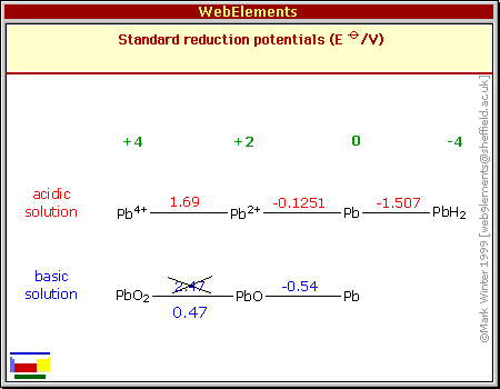
handbook, that had a major error: it showed the alkaline reaction
voltage from Pb valence 4 to Pb valence 2 (In this case PbO4 to PbSO4)
as being +2.47 volts when it's actually only +0.47 volts.
It's amazing how this one little number screwed up my
thinking on the whole subject for several years. 2.47 would have meant
spontaneous self discharge, and that lead couldn't work in alkaline
solutions - in fact, doubtless only in pH 1 acid. Thus, when people
talked about "converting lead-acid to alkaline" I thought they didn't
understand the chemistry, that it wasn't possible. But it was me
that was in error.
Instead, the less acidic the solution is, the lower the
voltage should be, down to .47 - -.54 = 1.01 volts with alkaline
electrolyte, or 6 volts for a normally 12 volt battery. This now (aha!)
fits with the lowered voltages I observed when I added an excess of
sodium sulfate.
This in turn may explain some of the "failures" where
everything seemed fine until the voltage suddenly started to drop
during charging and cells seemed to short or something: The voltage
wanted to be lower and the chargers kept trying to bring them up,
perhaps until
they started frying them, since they were really already fully charged.
Also, when I would see 11 volts instead of 13 or 10
instead of 12, I would assume a cell had shorted out. I was continually
perplexed by these supposed "failures" of cells in the batteries.
It seems possible that batteries with "too much" sodium
sulfate, or perhaps too little acid, probably work fine but might need
a custom charger for their specific voltage. I could also see this
might complicate the individual battery monitor, too. 10.5 volts is
alarm territory for a typical lead acid, but that might fall to say 9.0
or even lower for less acidic renewed ones, and an alarm at 10.5 would
be a nuisance.
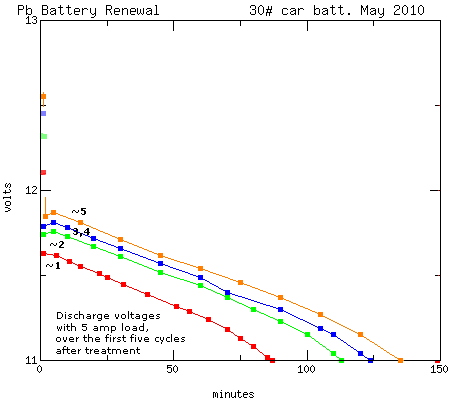
But this seems to be a moving target. On the second
discharge, voltages seemed to be even lower, but third charge ended a
bit higher. The third discharge seemed to hold voltages a little
higher. This is what others mentioned, and I'll revert to this graph
from TE News #28, which shows how voltages rose for me in one renewal
over 5 charge-discharge cycles:
Now seeing the chemistry a little more plainly, it would
appear that the reduced acidity accounts for the reduced voltage. But
the battery should become more acidic as it pulls sulfate off the
plates
during charging and discharging, as part of the renewal process, thus
raising the voltages. The half reactions forming acid are the regular
ones, with the voltages modified by the pH neutral Na2SO4 salt.
2 H2O + PbSO4 => 2 H+ + PbO2 + H2SO4 + 2 e- [+1.7v in acid]
PbSO4 + 2 H+ + 2 e- +> Pb + H2SO4 [-.35v in acid]
and of course if there's enough acid, the Na2SO4 + H2SO4 will no doubt
dilute to 2 NaHSO4 (sodium bisulfate), which is pH 1.
Will the battery always become fully acidic again? It
probably depends on the quantity of sulfate that comes off the plates,
and the quantity of sodium sulfate salt that was put in. Is "full"
voltage and strong acidity the aim, or will the renewed battery last
far longer if it's somewhat less acidic? It would take a lot of testing
over time to be sure of that, but it certainly seems batteries with
sodium sulfate (or, second best IMHO, AlNa(SO4)2 - alum) last far
longer
than plain acid ones.
An interesting aspect of this process is the rising
starting voltage (squares at left edge). I had back then a "cheap" old
charger with lower current that wouldn't try its best to fry batteries
that wouldn't quite come up to voltage, allowing the battery to survive
a few cycles without manually cutting off the charger. At first, the
battery wouldn't hold over about 12.1 volts, but by the fifth cycle it
was over 12.5.
Knowing now about the reduced voltages with rising pH, and
that the pH can in fact rise without without causing mayhem, it would
have been nice if I had graphed it down to 6, 8 or 10 volts instead of
cutting it at 11.
A Battery Renewal
Since I bought the Mazda and tried, seemingly
unsuccessfully, to renew some batteries to use with it, I've avoided trying to do any more. In early
July another battery in the Mazda was getting weak. I was driving it
quite a bit, and on the 9th I decided to try renewing a weak one one I
previously removed - as per my original plan for making them last well
- before I again had to run out and buy another one.
I took two seemingly identical batteries and drained the
acid. I couldn't remember which was the right one. One had relatively
clear liquid; the other was black. I turned them sideways and sprayed a
hose with a pressure nozzle into the cells. The one was clear. The
other continued to emit black liquid as long as I cared to spray it.
Then one of my renters said that one was one he had picked up to trade
in, and he had set it with my little collection (along with another
that didn't look familiar). No wonder I was confused!
Of course I renewed the one from the Mazda with the clear
water. I used Britta filtered water. For sodium sulfate I used some
from a big pail I had made last year by neutralizing battery acid with
sodium hydroxide. (It's a rather violent reaction that froths strongly
and may suddenly foam acid up in your face if you add a little too
much. I did it to get rid of some sodium hydroxide I didn't want. I
don't recommend it - I've met a blind chemistry professor. Potassium
hydroxide has more gentle results. OTOH, of course the end product is
sodium sulfate for renewing batteries with.) This had bits of crud in
it and I had to filter it through coffee filters. I'm also not sure why
the pail had three layers: a fine white powder on top, solid white ice
under that, which would turn into similar powder if scraped, and then
yellowish ice in the bottom half of the pail, which imparted its color
to the water when dissolved. The yellow seemed to settle out after a
while (hours), so it may have been particulate impurity rather than
dissolved.
Having - apparently - unsuccessfully renewed some of the
previous batteries before they had enough sulfate built up on the
plates, I was nervous this one might not work out either. The battery
had (rather quickly in this case) become weak, but were all six cells
weak, or only some or even one of them? Each cell might be a different
case, and if some weren't ready for renewal, the whole thing might
again not work. It all seems trickier than when I first heard about
renewing batteries.
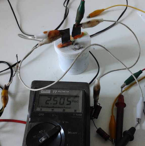
But there seemed to be nothing to do but refill the cells
with sodium sulfate in water. Initially it read somewhere around 11.85
volts. I put the supersonic pulse charger on it. After a while it was
up to 12.4 volts, but a while later it was down to 12.15 again. That
actually seemed promising - it could mean a cell that at first wasn't
conducting well had firmed up. After about 10 hours of slowly rising
voltage, it was over 14 volts and a while later said "full" and the
charger had dropped it to 13.2 for a float charge. The fact that it
took so long to get to full charge seemed to bode well for it having
good capacity. By then it was dark out.
The next day I tried some discharge tests at 10 amps. The
first one lasted 15 minutes and then the battery was under 10.5 volts.
Then I charged it a few hours again. This time, the voltage rose to 13
volts, then it went down to 12.3 and didn't seem to want to rise. Was
this another shorted cell? I ran it again at 10 amps, and it dropped to
11 volts quite rapidly, but below that, the drop slowed a lot. At 10.5
volts, each 10mV drop was taking 4 times as long. It started speeding
up again only when it was below around 9.6 volts, and it hit 9 volts
only after 40 minutes had elapsed. Right about that point the voltage
started dropping rapidly and I shut it off. It recovered to 10.84 volts
after a while, which seemed a little too high to indicate a cell might
be shorted. I put the charger back on, and it rose slowly right from
there, hardly rising even a millivolt until it was charged into it
rather than jumping up.
On the evening
of the 11th, I ran it at 10 amps for 50 minutes, at the end of which
time it was happily putting out 7.5 volts with only a very gradual
drop. When I think about it, as sulfate goes onto the plates forming
lead sulfate, there's still just as much sodium as with a full charge,
so as there's less and less sulfate in solution, more and more would
become NaHSO4 and then Na2SO4, and the pH would rise and the voltage
would drop. And at some point, as the sulfate in solution is exhausted,
one would even start to get NaOH - alkali. All this would produce just
the low voltage but still pumping out amp-hours condition I
was seeing. It may be these varying pH levels that cause the
crystallized sulfate to come off the plates and renew the battery.
I charged it overnight, and in the morning it was charging
at just over 14 volts. It would seem pulling the sulfate off the plates
in charging was making it acidic again, raising the voltage. In the 10
amp discharge test, it dropped rapidly under 12 volts, then the drop
slowed, but it was down to 10 volts in 20 minutes and in an hour to 8
volts. Repeated tests over several days showed it would run happily run
for at least three hours at voltages down to 7 volts and below, but it
didn't seem to be rising with cycling.
This Pourbaix diagram, showing Pb voltages
versus pH,
finally clued me in that the chart (far above) was wrong.
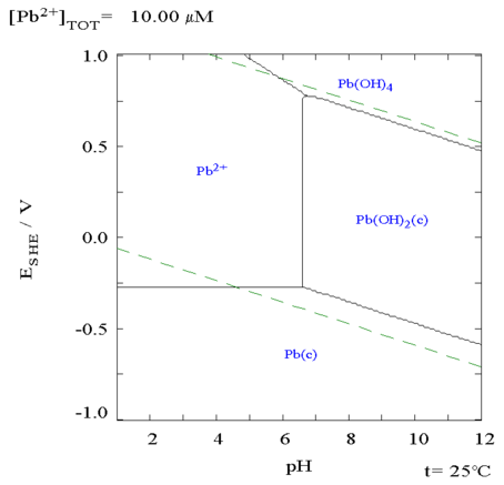 The pourbaix
diagram shows that at neutral pH, the
potential of Pb-Pb is only a little over 1 volt/cell, or 6 or 7 volts
for the whole battery - hardly changing at any pH above 6.5.
Notwithstanding that the test strips still show pH 1,
the acidity is - judging by the voltages - probably quite weak.
The pourbaix
diagram shows that at neutral pH, the
potential of Pb-Pb is only a little over 1 volt/cell, or 6 or 7 volts
for the whole battery - hardly changing at any pH above 6.5.
Notwithstanding that the test strips still show pH 1,
the acidity is - judging by the voltages - probably quite weak.
After a few days of this seemingly unprogressing (but
revealing) cycling, I decided to put the battery in the electric Mazda
regardless of the low voltages.
It was suddenly much easier to see what batteries were doing in the car
with the individual battery monitor (however crude) showing 6
batteries: the front 5 and any one in the rear - of course the renewed
one for now. I would quickly know if
it dropped off to still lower, or even negative, voltage under heavy
loads.
In the first test drive on the 19th, I went about 3.5
miles.
The initial voltage was 10.7 and dropping after I unplugged the car,
but it soon went down to 7+ with lighter loads, and down to about 6 or
less when I needed power and 'hit the gas'. (not that I
drove anything but frugally on the first trip - later it was going
under 5 volts under heavy loads.) Once it was down to those voltage
levels,
there was no notable continuing reduction over the 3.5 miles. Before I
treated it, it had gone flat rapidly after 3 or so
miles, a distance shrinking notably with each drive. So apparently I
renewed it successfully but turned it into a
lower voltage battery. What's it worth as such? Typically I see 11.5
volts under moderate (for a car drive) load, and this one's showing 7.
On the face of it, the lower voltage
means it's 7/11.5=61% as much energy. With heavier loads, the voltage
drops seem worse, but that's not most of the time. Nevertheless,
perhaps 55% is a more realistic figure.
This assumes the amp-hours stay the same. There's the
theoretical based on the number of molecules, and then there's what's
actually attained. Lead-acid battery performance drops a lot at higher
loads, increasingly with the load. My "85 amp-hour" size 24 batteries
may give 85 amp-hours at about 4 amps (20 hour rate), but in the car
where they're forced to deliver bursts of 150 to 200 amps or more,
they're
pretty
much pooped out before they've delivered 20 amp-hours, limiting the
car's driving range.
What if the sodium sulfate electrolyte causes them to work
better at high loads than acid does? Then the lower voltage could be
compensated for by higher available amp-hours, and the practical
difference could be much less than the theoretical. That would take
some test drives, evidently longer ones, to determine.
And cycle life is another important question. I understand
the 'converted' battery will go for hundreds of cycles and may be used
quite freely, where with the original acid they're only rated for
around 120 cycles at 60% depth of discharge -- and then only if
recharged immediately and never discharged too far.
It may be worth trying out mixing sodium sulfate and acid
and getting something that renews but holds more "normal" higher
voltages, but hopefully provides better current(?) and still lasts a
long time.
Pb-Pb is more than heavy enough per unit of energy as it is! Somewhere
is probably an "optimum" compromise.
Another observation is that once the battery is charged it
will rise up to 14.4 volts, but it quickly drops back down and it's
probably a waste charging it above 11 or 12. A common 12 volt power
adapter is probably all it needs for a float charge, instead of having
to hunt around for
uncommon 14 or 15 volt adapters.
On the other
hand, I hear now from someone that EV-ers say renewed batteries
gradually come up to voltage again, slowly, after many cycles. The
individual battery monitor in the car will show me this as and if it
happens. I may have put in too much sodium sulfate and it'll stay low.
The after-charge 'hold' voltage has gone from around 10.1 to 10.7
volts. If the voltage under load is improving it's imperceptible so far.
I also put sodium sulfate in the other battery. But my
ultrasonic
pulse charger to charge it with was tied up in the car with the first
one, so the second one just sat. I couldn't see resurrecting my awkward
home-made setup, so finally
bought another pulse charger on the 29th. Oddly, this battery that so
much black
lead stuff washed out of in the rinse, appeared to work better than the
first (higher voltages) and on the 31st I swapped them to see how it
would fare in the car. On the second trip, which was long, voltages
dipped down into the 2 volt range under heavy load. It whould be easy
to see if that improves! Both batteries seemed slow to react. They
would drop down heavily when power was needed, then the voltage would
rise up some even with the same current being drawn.
I'll have to see what another few weeks of use does. I
also found a third 'identical' battery to renew, and have a couple of
previously treated 'failures' still kicking around to try out, now
expecting the lower voltages that they've produced.
I ran a 4-headlight load test on the first battery
(supposedly 10 amps but probably closer to 7 amps at the lower
voltage), and it ran great for 4-1/2 hours from 7.29 to 7.00 volts. No
doubt it would have happily continued several more hours down to 6 or
less. Maybe I'll draw out some more of the solution (using the
hydrometer) and replace it with more H2SO4 and see what that does.
http://www.TurquoiseEnergy.com
Victoria BC