Turquoise
Energy Ltd. News #79
August 2014 (posted September 2nd)
Victoria BC
by Craig Carmichael
www.TurquoiseEnergy.com
= www.ElectricCaik.com
= www.ElectricHubcap.com
= www.ElectricWeel.com
Month In Brief
(Project Summaries)
- Electric Hubcap Motors are more powerful than previously thought!
-
Electric Weel - Turquoise Battery Project - Write-ups
& Website - Shopping & supplies - Aquaponics Greenhouse &
LED Lighting - VA Wind Turbine?
In Passing
(Miscellaneous topics, editorial comments & opinionated rants)
- Research and development tax credit programs - New video on financial
system - Overpopulation & Epidemics
Electric Transport - Electric
Hubcap Motor Systems
* Major magnet rotor improvement!
* "Bedini" unipolar motors?
* Huge Torque, Low RPM Electric Weel Motor-Generator Project
* Lightest magnet rotors
* J1772 car charging plug
Other "Green"
Electric Equipment Projects (see month in brief: LED grow
lights)
Electricity Generating (see month
in brief: VAWT.s)
Electricity Storage - Turquoise Battery
Project (NiMn, NiNi), etc.
* Improved plastic electrode pockets: two-piece 'boxes' with 'lids'
* Nickel-Nickel cell tests
* Lead-acid battery renewal update
No Project Reports on:
Variable torque converter transmission, Peltier heat pumping, Lambda
Ray Collector, Magnet motor, CNC
Gardening/Farming Machine (sigh, maybe summer...
2015?),
Woodstove/Thermal Electricity Generator,
evacuated tube heat radiators.
Newsletters Index/Highlights: http://www.TurquoiseEnergy.com/news/index.html
Construction Manuals and information:
- Electric Hubcap Family Motors - Turquoise Motor Controllers
- Preliminary Ni-Mn, Ni-Ni Battery Making book
Products Catalog:
- Electric Hubcap 4.5KW BLDC Pancake Motor Kit
- Electric
Caik
3KW BLDC Pancake Motor Kit
- NiMH Handy Battery Sticks, 12v battery trays & Dry
Cells (cheapest NiMH
prices in Victoria BC)
- LED Light Fixtures
(Will accept BITCOIN digital currency)
...all at: http://www.TurquoiseEnergy.com/
(orders: e-mail craig@saers.com)
August in Brief
Electric Hubcap family motors are more powerful than suggested
previously
The main concern with motor continuous power rating is
whether the motor gets
too hot at a given power. They're usually rated for the power they'll
handle without gradually exceeding their maximum temperature. The
materials of my motors (in particular the epoxy) are only rated for up
to about 65°c which is much lower than steel body motors, but being
highly efficient and having good cooling they
make little heat.
The concern for intermittent power rating above the
continuous power rating is how much power they're wasting, since
efficiency drops more and more as power is increased. Typically peak
efficiency is at 10-20% of full rating. Usually the high end testing is
ended when the power loss reaches 50%.
Judging from the almost trivial
motor temperature rises in the Electric Caik outboard at
1200-1500
watts in actual operation on the water, it appears that's a low
percentage of potential power and so I've been rating my motors
extremely conservatively. They could probably do
four
times the power I've been saying for short periods without overheating
(and without exceeding 50% loss), and maybe as much as double for
longer if
not
indefinite periods. At the risk of
maybe going overboard the other way, that would be: 12/6 KW
(Caik), 18/9 KW (Hubcap) and 48/24 KW (Weel). Very roughly assuming efficiency losses of 50% and 25% at
such high levels, output power would be 8/6 HP, 12/9 HP, and 32/24 HP.
Such figures might put a new complexion on what people decide they can
use Electric Hubcap type motors for.
Proper testing for which I have had neither the proper
equipment nor time to do so far would obviously be valuable. I've been wanting to buy a commercial BLDC
motor controller that won't blow up if I drive them to the levels
indicated above,
in lieu of beefing up my own controllers to 500+ amps capacity without
failing, which
they've hardly managed 1/5 of so far. So far, I've been putting it off
until I
(presumably) get my annual SR & ED tax credit from Canada Revenue
Agency.
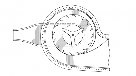
Electric Weel
Motor/Generator
 Large and Small:
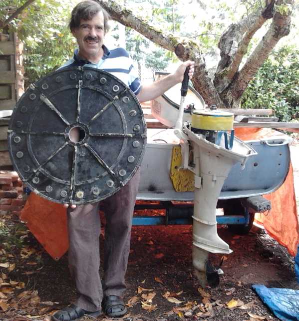
The newly made stator end piece for the huge torque, 28", 24(?) Kw Electric
Weel motor,
compared to the size of the outboard's 9", 6(?) Kw Electric Caik
motor.
In the early part of the month, I was molding a piece per
day, occasionally two, for the giant Electric Weel motor, and fastening
the pieces made in July together with polypropylene strapping and
the left over epoxy. Towards the end of the month I had two of the
three body pieces completed, the stator end piece, and the center piece
with a thick rotor side rim to safely enclose the rotor and stop any
magnets that might potentially come loose from flying out with
potentially deadly
force.
In spite of good intentions, the one additional mold piece
needed for the rotor end cover isn't made yet. (Two pieces from the 3
piece mold for the stator end cover can be used for both ends.)
This huge motor is certainly a lot more work than the
small units, with 24 moldings of body pieces instead of 3, then they
have to be epoxied together, plus a much larger rim that needed three
epoxy mixings instead of one. It's taking over 200 dollars of epoxy.
In a discussion, I also came up with a great way to
improve attachment of the magnets to the rotors: cut slots through the
rotor plate just inside from each magnet, and wrap the epoxied
polypropylene strapping right around the magnet and rotor plate from
inside via the slot to ouside around the rim. If I also balance the
rotors carefully, I think the Caik motor should be safe at at least
3000 RPM this way, whereas I've been reluctant to take it above around
2000 so far. This will be a major improvement to the whole family of
motors.
For the Electric Weel specifically, I got the idea
to use lexan plastic for the huge (26" OD) rotor instead of steel to
lighten it. Only outside where the magnets need steel backing will have
a steel ring. Even with the rotor lightened by having a 1/8" main body
with a 3/16" outer ring instead of being thicker throughout, the motor
with a steel rotor will weigh about 100 pounds (...that's the exact
figure I came up with in estimating it), and the plastic one can drop 8
or 10 pounds off that. Pounds count for handling and installation, and
in an EV it improves range that little bit.
 Electric Weel body parts so far, in
assembled position - now it
Electric Weel body parts so far, in
assembled position - now it
just needs the top (rotor) end cover... and all the other parts.
The first Weel is already spoken for for
use as a large, low RPM generator for a novel floating river
hydroelectric project by Rick Linden of Coastal Geosciece Research
Corp. (http://www.coastalgeoscience.ca/
- a website even more in need of update than mine!)
Being made specifically as a generator for lowest RPM, each rotor
magnet will
alternate polarity and it can't be used as a motor.
As
I
think
about this project, I wonder if it has the
potential to replace river dams with more environmentally benign
floating structures. One thing working against this idea regardless of
the efficacy of the generators themselves, is that dams usually are
used to store winter rain water or snow melt for the dry summer season.
But it
could probably harness river and stream water that wouldn't otherwise
be harnessed at all. A hydro dam magnifies and harvests nearly all the
energy at one point in the stream, or perhaps it should be said, of the
section of the stream that the reservoir backs up to. Each floating
unit won't harvest a major portion of the flow, but they can be
placed up and down a river to harvest it at as many points as are
desired or seem useful. The aggregate just might rival a
showpiece dam project. Or it might complement it because if a dam
holds back water for summer, floating units downstream will also have
water flow to work well in summer.
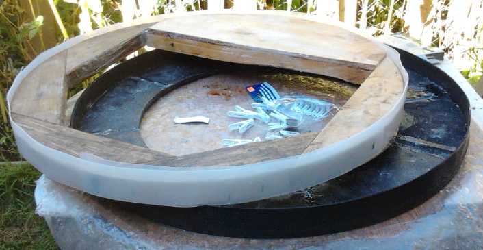
Turquoise Battery Project
With the 3D printer repaired, on the 4th I printed a bunch
of electrode containers... each pair improved a bit over the previous
as I saw flaws. But leaking electrodes from July's batteries, which I
finally abandoned for that reason, got me thinking about an idea for
improved
plastic battery electrode 'pockets'... something like little boxes...
where the sides
of the box slide over each other, so that no matter the exact thickness
of the electrode materials, there'd be no gaps around the edges. If it
seemed helpful, I could even glue the edges together. (Fearing the
usual paper deterioration I'd rather not glue prototypes and then be
unable to open it to replace the paper, but it's doubtless the way to
go for production.) But somehow I hadn't had time to get it done.
 On
the evening of the 11th after dinner, I finally decided I just had to
get this together. Working around some frustrating idiosyncrasies of
the 3D printer - actually mainly of the printing program - I had a
workable pair done by about 1:30 AM. (It occurs to me I should download
a new version of "Pronterface" in case there have been any improvements
that would help.)
On
the evening of the 11th after dinner, I finally decided I just had to
get this together. Working around some frustrating idiosyncrasies of
the 3D printer - actually mainly of the printing program - I had a
workable pair done by about 1:30 AM. (It occurs to me I should download
a new version of "Pronterface" in case there have been any improvements
that would help.)
I made a nickel negative electrode that crumbled, then
another one, and put it in one of the new boxes. By then the end of
the month was approaching and I decided to leave it until my conductive
carbon black arrived to make a better positive side from. Supposedly
that should have been shipped on the 24th, but it hadn't arrived by
September 1st.
Electrode boxes that I hope should serve to
prevent leakage
of electrode substance into body of battery cell
Write-ups & Website
From the 12th to 17th I was busy writing up info Canada
Revenue Agency ("CRA") wanted to have preliminary to a technology
review and inspection of
Turquoise Energy's facilities, the first since their initial visit over
four years ago. There was a deadline for submitting it. I finally
mailed off about 40 pages of info on the 17th, a little about finances
but mostly about the projects claimed last year.
Having done a sort of an 'overview' writeup on each
project, I plan to use the material to update the Turquoise Energy
website. I've put more about the tax credit funding subject, and its
stormy history, in "In Passing".
And I finally started a rewrite of the Turquoise Energy
web site on the 31st. A couple of weeks previously, Jim Lawrence came
over and went into web page CSS coding with me. CSS 5 has new features,
created
since he had done up the website for me in 2011 in CSS 3, which make it
far simpler to do what he did then. In several frustrating hours I had
the commands worked out to create similar article frame borders in two
columns
to what he had done then, but which were then so complex they got
messed up
every time a change
was needed. I kept the upper part of the page with the menus and links,
and the footer part with icons and links to twitter, facebook, etc, and
the appearance of the main section but with the new CSS 5 coding. Of
course, after three years most all the projects are much
farther along and needed or still need major revisions. It'll take a
couple more sessions before I can upload the new main page, and then
the other pages can follow one at a time.
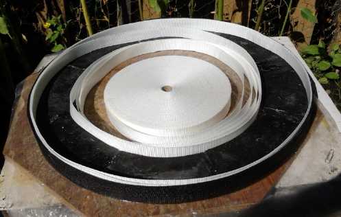
Shopping - Supplies
I spent the whole day of the 21st shopping for various supplies, in
particular for the Elecric Weel motor, and a cheap flux core wire feed
welder to help with building a new 'box' for the variable torque
converter transmission. I find the considerable time I have to spend
either visiting stores or sitting on the computer looking for and
ordering things this somewhat
frustrating, as well as seeing the money go out, when I want to get
building. But one can't build without parts and materials. I got a
great deal at a tent and awning store on
1.5" PP strapping for the rim of the rotor compartment (the immediate
concern) - a 60 or 70 yard roll of white that the clerk said had been
'kicking around a long time' and had become a bit discolored, for about
1/3 of the regular by-the-yard price.
Aquaponics Greenhouse - LED Grow Lighting
Access to the greenhouse is
through the garage wall for security.
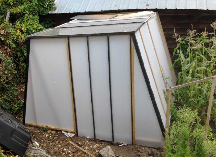 Making the
greenhouse dragged out through the whole
summer, since I didn't put much time into it. Finally I put on the last
outside "coroplast" panel on the 29th. There's still work to do on it,
but I now have an enclosure.
Making the
greenhouse dragged out through the whole
summer, since I didn't put much time into it. Finally I put on the last
outside "coroplast" panel on the 29th. There's still work to do on it,
but I now have an enclosure.
It seems the federal government would love to see
food being grown in the arctic in greenhouses, since it costs a fortune
to have it flown in for workers and residents in the far north. I got a
5 meter RGB - LED strip light from Jim Harrington on the 23rd, and it
seems I've
sort of been volunteered to work on ways and means for the lighting. It
can be cut into sections or bent around, and it even has a remote
control. I also have the
blue and red plant-grow wavelength LED.s I purchased myself for flat
panel grow lights.
Victoria isn't the frozen north, but it's certainly a
challenge to try and keep a greenhouse warm and lit and grow food here
in the winter, so maybe things worked out here could be applicable. If
I'm to keep tilapia fish for aquaponics, the water certainly needs to
be kept warm, and so does the greenhouse to grow plants. The tilapia
tank (to
be) is an apartment size fridge (insulated!) that holds water nicely if
it's lying on its back, as I found when I first saw it that way lying
on an
old pickup truck. The idea for an insulated fridge or freezer I got
from "cold weather aquaponics" on
youtube, where others are also working out the challenges of growing
food in cold climate greenhouses. If I'm able to contribute anything
new or special to that work, it'll probably be in the LED grow lighting
area and maybe renewable energy supply. (Perhaps I should contact
them...?)
The adhesive backed lights could simply be stuck to the
underside of a metal strip -- eg, aluminum angle irons. These would let
all the light shine down from above the plants, while the vertical part
placed at the front would shield the LED emitters from peoples' eyes.
This much sounds simple enough.
Aquaponics is apparently an excellent way to provide food
for people from small spaces with very minimal inputs in supplies:
fish food, water (but it's mostly recycled), energy and labor.
Vertical Axis Wind Turbine
 I have again been thinking some about the VAWT idea. It has occurred to
me to make a very miniature version on the 3D printer. Or I'd make a
larger "real" version with the top and bottom pieces (and maybe a
center piece?) to hold the blades cut precisely on the CNC router.
I have again been thinking some about the VAWT idea. It has occurred to
me to make a very miniature version on the 3D printer. Or I'd make a
larger "real" version with the top and bottom pieces (and maybe a
center piece?) to hold the blades cut precisely on the CNC router.
And I ran across an interesting so-called "bladeless"
turbine. Of course it isn't bladeless, but the blades are inside a
housing something like the one I envisioned a while back to "aim" the
wind at the blades better, but still more elaborate and allowing more
efficient wing-like blade shapes.
Of note, where I would orient this unit with a vertical
axis and a vane so the housing would pivot about the shaft axis to face
into the wind, the authors had it horizontal. In that case the entire
unit would pivot including the generator at one side.
It should work about the same either way, but with a
vertical axis the generator can be in a fixed position underneath with
no need for slip rings to wire it.
In Passing
(Miscellaneous topics, editorial comments & opinionated rants)
R & D Tax Credit Programs (Canada, history)
In July I got some notice from CRA of several pages,
saying that they wanted to do a finance and technology audit on
Turquoise Energy's work. Being in the middle of projects I ignored it
for 3 weeks, then read it and discovered there was a 30 day response
time limit. From about the 10th to the 17th I was busy writing up the
info they wanted preliminary to an inspection of my facilities and got
little done on the actual work beyond molding 2 or 3 more sections of
the big Electric Weel generator. I finally mailed off about 40 pages of
info, a little about money but mostly about the seven projects TE
claimed
for last year. When I first submitted SR & ED investment tax credit
forms in 2010, someone from CRA came to make sure I was doing what I
claimed, and this is the first time since then they've wanted to do an
inspection. I think that the Turquoise Energy News monthly reports
being on line has been considered sufficient proof for quite some time.
Notwithstanding the time it took me to get this together,
seemingly the same as if my 20000$ tax credit claim for 2013 was for a
million$, Canadian taxpayers
should be pleased
that the SR & ED tax credit program, based on a percentage refund
of resources
already invested by companies in R & D, is doubtless a pretty tough
program to scam. And it's about the only government program open to
those doing quite speculative inventive work. Most funding sources
forget there's "D", development, in R & D, and it's much harder to
get funding for creating new products than for "R", research.
I remember the early 1980s... 1984 or so (the fermenting,
enthusiastic early days of
computing) when "Scientific Research Tax Credits" ("SRTC"s) were frist
introduced and Frank Hertel scammed 70 million dollars
of taxpayer money with vague, then unworkable promises of remote power
meter
reading, and Fitsch(sp?) of 'Fitsch Research' got 35 million. (Both
fled to Venezuela with their 'winnings'.) Any number of smaller players
also scammed millions, while those actually doing R & D couldn't
get funding except through these high profile companies in trying to
make themselves look legitimate.
Hertel had a history of bankrupt companies behind him in
Germany, as anyone who bothered to read his resumé and check out
his references would have
discovered. An astute prospective employee came back laughing after his
interview and said the whole thing was an SRTC funding scam.
Where was the government's "due dilligence"?
Fitsch research tried to hire me in late 1984... not when
I
applied, but some months later. I got an interview when, as it turned
out, they were about to be audited to justify the lavish amounts
bestowed upon them. They wanted me to start immediately
and go to California and design IC memory chips. I had good experience
designing products using IC chips, not actually designing the chips.
And it all seemed too rushed. Where were they when I was free and had
offered my talents 3 or 4 months before -- and why hadn't they
interviewed people in good time? A month or so later Fitsch was in the
newspaper as the sheriffs were removing the furniture from their
offices. I expect I'd have never got a paycheque and would have been
left to hitchhike home from silicon valley.
Another Documentary on the crooked money system: Century of
Slavery: History of the Federal Reserve
In a similar vein to Mike Maloney's educational Hidden
Secrets
of
Money
Episode
4 now comes James Corbett's Century
of
Slavery: History of the Federal Reserve, 'an intense 7 months of
work' according to Corbett. It's been released free at
CorbettReport.com and on YouTube.com, and there's a full 90 minute
version or a condensed 55 minute version (which is the one I watched).
Corbett goes into more detail about the specific history of banking and
money in the USA than Maloney in this very watchable and informative
documentary. Both producers stress that the best way to help yourself
prosper and keep from being inexorably bled by the deliberately
complex and
confusing ponzi game financial system, is to educate yourself
about how it works.
Financial and Economic Collapse and Epidemics
As economic conditions worsen and the financial system
implodes, and with worldwide travel, it becomes more and more likely
that some of the various serious diseases in the news - such as MERS,
Ebola (evidently it's airborne, BTW), Dengue fever, and various
virulent forms of
flu - are likely to start sweeping across populations weakened by
overcrowding, poverty and shortages of nutritious food. With a still
growing global population (even tho that growth has at last slowed
considerably except in a few countries), and grossly inequitable
distribution of wealth, a crash of global systems and
with it the "population bubble" has in fact become inevitable.
In the middle ages black plague, coming "out of nowhere"
via rats brought from Asia in ships, gradually killed over half the
population of Europe in the only recorded century so far of global
population decrease. (It was said that while no one was immune, the
"lower and meaner" sorts of people were disproportionately affected. We
might suspect that many of these were less "cultured" groups with
poorer nutrition and lower
standards of hygiene... such as it was back then.)
In 1919 and 1920, at least Germany and parts of Europe
were starving, and an influenza epidemic killed more people (tho
worldwide)
than the devastating first world war (fought mostly in Europe) that it
followed. Antibiotics now available can mitigate bacterial diseases,
but viral ones like flu still can still sweep through populations, as
we all well know. Flu vaccines are apparently not very effective, and
also
vaccines have been implicated as a major cause if not the major cause
of autism. (An interesting study showed the great flu epidemics were
also
statistically linked to schizophrenia: it was noted at a British
psychiatric institution that schizophrenia was commonly grouped into
very specific age groups, which correlated to mothers being apparently
4-5 months pregnant at the time of a flu epidemic. Since the
correlation wasn't noticed until decades after, when the patients were
adults, it wasn't determined whether the pregnant women had to contract
the flu, or merely be exposed to it at the wrong time.)
Vast tracts of the interior of my large province of
British Columbia were planted with nothing but pine trees. A usually
minor pest, the pine beetle, started multiplying and spreading until it
infested the whole province, killing vast pine "forests" (plantations?)
provincewide. (I expect most farmers can tell us the hazards of crop
monoculture.)
Starfish have been in the news a couple of times in recent
years now. First
it was because they had been multiplying in numbers to the point where
it was feared they would utterly destroy all the world's coral reefs.
But this
overpopulation bloom has now brought a plague on the plague of
starfish, and they have been lately in the news again, this time for
dying off en masse of some
disease that rots them away.
When any species has grown in numbers too large for the
available resources to sustain (in the human case,
farming and land for all purposes), epidemics strike. Instead of a
leveling off of population with barely enough for everyone, there is
disease and a
population collapse. With seven and a half billion people in the world
today many vast areas are overpopulated compared with what current
societal and technological conditions can support. Diseases will soon
have a golden opportunity to wipe out maybe 2/3 of this mass of
people to produce a second century of global population drop, and a
very substantial one. I won't say the planet can't support this
population. If seawater were desalinated and the deserts turned into
gardens, if resource distribution and population distribution were
equitable, it might. But would the population then cease to grow,
or would it continue increasing until it was unsustainable at an even
higher level?
As it is, the three cosmic core values (quality of life,
growth and equality) are out of reach for too many people. The
reduction of pressure from our species
will be a welcome relief to the Earth. The lesson taught by the global
devastation will probably not be lost on the remaining populations
everywhere. They will probably decide that having children in
uncontrolled numbers isn't a right, and maybe that improving all the
human races by selective breeding to reduce the proportions of
"challenged" children
and increase those of the more intelligent and physically fit, only
makes sense. The Universal Father loves every person equally, but he
doesn't need for large percentages of them to continue being born with
various
built-in
genetic problems that detract from their personal growth potential and
from building the utopia that every
inhabited world should become.
Electric
Hubcap
Motor
Systems
-
Electric
Transport
Magnet Rotor Mechanical
Improvement!
My magnet attachment setup for the magnet rotors was the
best I could come up with at the time. But all along, I've been
somewhat
uneasy about it. The polypropylene strapping is strong stuff, but
keeping it attached to the rotors and the magnets glued to it, all
withstanding high centrifugal forces at higher RPM.s without something
delaminating, has been
something of a challenge. It was worst with the first attempts at the
Electric Caik rotor, where the slick coatings on the new magnets let
them
slip right out of the 'sleeves' at a very low RPM, and even after
sanding them to give the epoxy a better grip and re-doing the rotor, I
decided I didn't want to run it above 2000 RPM when I had originally
intended 3000.
I've thought of a new pattern or two for the strapping
that would cover the outer end so the magnets couldn't slip out. I
haven't made a new rotor since, so this never got put to the test. But
the whole thing, epoxy, strapping, magnet and all, could still
delaminate and pull away from the rotor with enough centrifugal
force. Some way to definitely attach the inner end of the strapping so
it absolutely couldn't pull off with any force less than required to
rip the very strong strapping itself would be much better.
In considering the magnets for the Electric Weel motor
with its two-piece rotor on the 11th, I finally thought up a truly
better answer: make a slot through the rotor just above the inner end
of each magnet. The strapping can be pushed through the slot and
wrapped right around the magnet on the rotor vertically (from inner
slot to outer rim), overlapping itself on the back side, and of course
all
epoxied into place. Even a loose magnet couldn't slide out, and the
strapping would have to tear to pull away from the rotor at the inner
end.
With this arrangement, which I will adopt for
all, the
rotors will be much more robust and able to withstand considerably
higher RPM s without flying apart. Maybe I'll have the Electric Caik
motor doing 3000 RPM or more after all... and maybe even get the 14'
aluminum
motorboat up planing!
After over 6 years of motor development, here was a place
to fix a remaining real design weakness that's been nagging my
thoughts! Counting moving the bolts farther from magnetic fields so
they don't get hot,
that'll be two new improvements, and of course the motors will be
better
than ever!
Rotor balance didn't matter much under 2000 RPM, but it
does anywhere much
above that. One can figure out where the imbalance is by putting the
rotor on an
axle and setting it on the axle between two perfectly level
rails. It'll roll until the heavy side is down. Weight would then be
added to the top side or removed from the bottom.
Unipolar
"Bedini"
Motor-Generators
There's "efficiency" from 0 to 100%, but with some systems
such as heat pumping, there's also "coefficient of performance" which
yields energy performance substantially in excess of the input energy.
Could there be such a thing with motors as well? Could my 95% efficient
motors be radically improved? John Bedini seemed to have demonstrated
it in the 1970s with his unipolar motors.
The more I considered it, the more I liked the idea. With
a regular motor, when a permanent magnet is between two coils, the coil
behind pushes with an energization the same polarity as the magnet (eg,
both south), while the coil ahead is magnetized to attract the magnet
(ie, north). But the iron in the coil itself also attracts the magnet
regardless of polarity, even if the coil isn't energized. If only the
coil behind is energized to push, the coil core ahead still pulls on
the rotor magnet, and regardless of polarity. The motor has magnetic
"cogging" and wants to jump to certain points of rotation where magnets
line up with coils.
Furthermore if the coil isn't energized, it can be used to
generate electricity just where the magnetic attraction pulls the
rotor, and
also the collapsing field from when it was energized can be recaptured.
With light mechanical load, Bedini seemingly had it generating as much
electricity as it used, charging a second battery even while
being driven from the first. The rumored Japanese e-bikes I heard of
last month, evidently using unipolar motors, apparently have far
greater travel range than others.
One could make a motor controller to do the Bedini 'trick'
with
bipolar magnet rotors - but with double the MOSFET drivers in order to
activate each phase independently north or south. With unipolar rotors,
they only need to repel one polarity so they only need to be activated
in one direction, making the controller much simpler instead - with
half the
MOSFET legs (3) instead of double (12) of the common BLDC controller.
The "Y
point" of the coils is tied to the battery plus voltage ("B+") instead
of left floating. The
three phases of coils are then actuated independently just by pulling
the other side to
ground. So the 3-phase bridge changes to 3 pull downs, eliminating
the high-side mosfets - half the heat-making power transistors and the
complexity they add.
Tying the "Y point" to B+ has another benefit: when the
magnetic field collapses after powering the coil, the voltage reverses.
With the Y point floating at 1/2 the supply voltage, this voltage
doesn't get higher than the battery voltage unless it's greater than
1/2 that voltage already (and even then perhaps it just pushes the Y
point around a little), so some of the resupply of power back to the
battery is lost. With one side of the coil at B+, all unused energy
(above the .5v reverse diode drop) is returned.
Furthermore, a 'regularly' configured motor has to go fast enough to
generate more voltage than the battery in order to passively recharge
it. But with one end of the coil at B+, the coil's back EMF would
generate electricity above the battery voltage whenever it's off and
the polarity is right. (Do I have that right? There seems to be
no ground reference for the coil voltage at this point. This may be
where Bedini charged a second battery - because the circuits didn't
work out for charging the same one supplying the motor. To charge the
same battery might need some sort of charge pump or an isolated output
DC to DC converter. This needs more thought.)
A complication with the control arises with the magnet
sensors. With alternating north-south magnets, the hall sensors can be
pretty much relied on to switch back and forth at the center points
where the field crosses zero. There are unipolar hall sensors, and even
with
unipolar magnets, south and north fields alternate if the sensors are
strategically placed, but the fields are unlikely to be even lengths. I
can see having to go back to the optical sensors I was using before I
found out about Hall sensors. Those of course will have to be mounted
in the rotor compartment rather than more conveniently in the stator
compartment. If I adopt lexan plastic rotors, a new idea mentioned in
"Electric Weel Project" below, they could perhaps be painted with the
appropriate stripes, and the LED.s and sensors be placed on opposite
sides of the rotor.
Huge Torque,
Low
RPM Electric Weel Motor-Generator Project
On the 8th I got
back to this and I wrote the G-Code (mostly by cutting and pasting from
the lower piece) and made the 3rd piece of the stator-rotor division
mold with the CNC router. Again the parts would be in eight 45°
pieces to be fastened together into a complete ring. On the 9th I
finished tidying it up and drilled and threaded holes for bolts to
clamp it together. I let the first piece harden up well before removing
it, thinking it might just pop out easily, but I almost wrecked the
mold getting it out. After that I waxed
the mold.
On the 10th & 11th I made a piece each day and 2 on
the
12th. I finished on the 19th, skipping the odd day because of the time
spent to write the CRA info. At the same
time, I used the epoxy that squeezed out of the mold to start gluing
the outer end (8 pieces molded in July) together, strengthening the
seams with PP strapping on the outside. It's hard to do more
than one in a work session because the epoxy in the mold has to set.
Also it takes a while to clean out the mold and get everything ready
for each one. It's far more work to do this large motor than the small
ones!
When I do a second unit, I can use the different molds and
maybe do 2
(or even 3?) pieces at a time. (if I buy a bunch more 4" C-clamps.) But
I took this one slow to see how
the molds worked
out - I might (and did) want to change something.
Also probably worthy of note is that owing to some of the
parts turning out a bit dry of epoxy, I'm changing the ratio of 4
epoxy to 1 polypropylene cloth, to 5 to 1. That's by weight - the light
cloth is still over half of the bulk.
On the 21st I needed supplies in order to proceed, and
spent the day shopping. But I got a great deal on
1.5" PP strapping for the rim of the rotor compartment - a 60 or 70
yard roll of white that the clerk said had been
'kicking around a long time' and had become a bit discolored on one
edge, for about
1/3 of the regular by-the-yard price.
The next day (22nd) I decided I'd do the outer part with
2"
strapping instead of 3", and alter the form for the top. Now the entire
rim would be even height, and the cover piece would be the full motor
diameter and made with a lip just inside of the rim to 'lock' it into
position. This was in
fact the reason I hadn't made the top mold piece(s) yet - just in case
the design changed before I got there!
 I
didn't have enough 2" strap and bought 15 yards at
regular price. Then I made a big wooden ring to fit inside on top of
the center body ring, to wrap the epoxied strapping around to make the
outer part of the rim. (The wooden form was also modified - lower -
because of the rim change.) I made it out of 2" boards screwed
together.
These would be waxed
and a liner strip of 1/16" thick polyethylene plastic would be wrapped
around the wood, to keep the epoxy from sticking to the wood. In the
worst case, unscrewing some of the boards from each other should free
up the wood from the rim after the epoxy hardened. (Wasn't necessary.)
I
didn't have enough 2" strap and bought 15 yards at
regular price. Then I made a big wooden ring to fit inside on top of
the center body ring, to wrap the epoxied strapping around to make the
outer part of the rim. (The wooden form was also modified - lower -
because of the rim change.) I made it out of 2" boards screwed
together.
These would be waxed
and a liner strip of 1/16" thick polyethylene plastic would be wrapped
around the wood, to keep the epoxy from sticking to the wood. In the
worst case, unscrewing some of the boards from each other should free
up the wood from the rim after the epoxy hardened. (Wasn't necessary.)
On the 23rd I epoxied the center body ring pieces
together. The main trick to this was to make sure the 24 sets of coil
buttons matched and the coils fit on both sides. With the stator end
ring already made, later adjustments would be difficult. Luckily
PP-epoxy has just a bit of flex. The other
trick was to get them even so nothing stuck up to where the magnets
rotate. I bought some plastic clothes pegs. I ended up just using the
angled pieces as shims to adjust heights to evenness, but they were
probably the best thing I could have used.
 On the 25th I
waxed and then set up the wooden ring on the
motor body center ring piece (I had to wait for Monday to buy some PE
plastic to line the outside edge). I painted epoxy onto the outside of
the body center ring and onto the 2" wide webbing, and wrapped two
layers around the outside. Since the center ring's outside edge is 1/2"
thick, the webbing stuck 1-1/2" up above, forming the outside edge of
the rotor compartment. After a few hours I pulled the wooden ring out
of the middle.
On the 25th I
waxed and then set up the wooden ring on the
motor body center ring piece (I had to wait for Monday to buy some PE
plastic to line the outside edge). I painted epoxy onto the outside of
the body center ring and onto the 2" wide webbing, and wrapped two
layers around the outside. Since the center ring's outside edge is 1/2"
thick, the webbing stuck 1-1/2" up above, forming the outside edge of
the rotor compartment. After a few hours I pulled the wooden ring out
of the middle.
 For wrapping the inside of the rim I "spooled"
the strapping within, then started painting it with
For wrapping the inside of the rim I "spooled"
the strapping within, then started painting it with
epoxy and pressing it against the now solid outer rim to form a thick
solid wall.
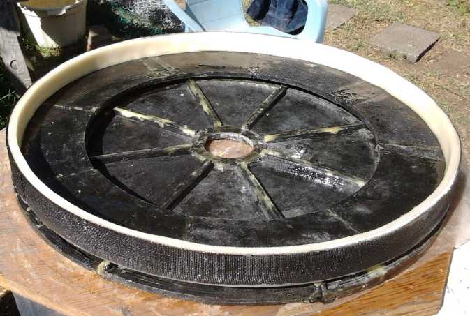
Electric Weel
axial flux Motor or Generator composite body, 28" diameter:
Stator end is under midsection with thick rotor compartment rim (white).
(The pieces are held at finished spacing by unwound coil cores, not
visible.)
Material: "Advanced" molded composite of epoxy, and polypropylene cloth
ripped
into 6" square pieces or 2" & 1.5" polypropylene strapping or
"webbing" (rim).
On the 26th I used 390 grams of
epoxy in three mixings and
7 layers of white 1.5" strapping wrapped around the inside to thicken
the rim
to 1/2". (it was a bit more - I'll do 6 layers next time.) I tried to
paint fast, but the day being
unusually hot and sunny for Victoria BC, first little tub of epoxy
started to smoke and set up before I had finished. I salvaged the brush
by putting it in the freezer. For the second two, I moved out of the
sun, and I kept the plastic tub of epoxy in a slightly larger plastic
tub of ice water. I tried to make a little video of Electric Weel
Motor Construction as I went, but without a camera person I
couldn't show doing the actual work - I'd have gummed up the camera
with epoxy.
When I was done I set the piece in the sun to set. With
the black plastic outside and white inside, the sun facing side got
quite hot and was soon set, so I turned it around. A while later it was
solid, and I sanded off some sharp edges with the belt sander. It had
been an all day project, with breaks for breakfast, coffee, and later
to lop off some blackberry canes that were threatening access to my
carport.
Despite good intentions, I didn't get to laying out and
making the mold piece for the rotor end cover pieces in August. The way
I did the rim, two of the three pieces for the stator end can also be
used for the rotor end, and only one new piece needs making.
Lightest Magnet Rotors? - Electric
Weel Total Weight Estimate
With a 26" diameter rotor, a 5/16" thick steel rotor would be horribly
heavy. I've thought of various ideas for making it lighter. The way
I've done the first one is with a 1/8" steel disk, with a 3/16" ring at
the outside where the magnets are, welded together and making 5/16"
thickness to carry the magnetic fields. I then had pieces of 3/16" disk
left over: an 18" disk that I had planned to use for the center of one
end of the plywood body, and a ring about the right size for a bicycle
wheel magnet rotor but only about 1.5" wide when I have all the 2"
magnets and coil cores.
Before that, as an earlier TE newsletter or two show, it
first occurred to me to make the whole thing as a
frame, welded together. 'Spokes' with transverse cross section would
give it more structural strength against warping and bending. That was
actually my first plan, but as I put it together, I was losing
confidence in
the strength of my structure at higher RPM.s, and at the same time, I
found the CNC waterjet steel cutting companies and did the above
mentioned design.
Now it occurs to me that a lexan plastic rotor, perhaps
bolted to a steel center disk to connect it to the shaft, would
probably be lightest. This would then have a steel ring on the outside
where the magnets go. I may even cut off the welds on the present rotor
and
keep the 3/16" ring but replace the center disk with lexan.
Weighing the parts (# = pounds), I find:
Coil end of body - 8 #
Ring part of body - 3 #
Coils - 23 #
Shaft (short), SDS bushing, bearings, bearing holders, seals - 12 #?
Magnet rotor (metal) - 27 #
Attempting to estimate the total weight, I get:
Total body - 25 #?
Total Wiring - 26 #?
Rotor (metal) with magnets - 37 # ?
Shaft etc. - 12 # ?
Total: 100 # even.
That's no doubt quite light for such a motor, at the
bottom
end of what I thought might be expected, and it'll certainly be easier
to handle than 150 or 200 pounds. But the plastic rotor would shave a
few
more pounds off it.
(Let's see: area of circle = pi * radius^2
= pi * 13"^2=530.9 sq". Area * .125" thick = 66.4
cubic".
The outer 3/16" ring is about 10-7/8 I.D. so 371.5 sq". inside
has no metal.
530.9 - 371.5 = 159.4 sq". * 3/16" thick = 29.9 cubic"
66.4 + 29.9 = 96.3 total cubic".
rotor 27# / 96.3 cub" = .28 #/cub".
ring 29.9 cub" * .28 #/cub" = 8.38 # weight of ring
8.38 # - 27 # = 18.6 # weight, of main rotor piece, removed.
)
Add the weight of the lexan and center hub for it, about 8
pounds, and the total weight reduction of the motor is about 12 pounds
for a total of about 88 pounds. That's probably worth it, although it's
still winch territory rather than "by hand" to install. And it's a
little less steel to rust. OTOH there's now only 3/16" thickness of
steel to carry the magnetic fields instead of 5/16". Since I don't know
the optimum thickness anyway... I'll just ignore that!
It would be nice to eliminate the steel altogether. I
could then make the rotors by layering lexan type plastic (for the
inner hub), glued with methylene chloride, and having the CNC router
precision cut everything including rectangular holes for the magnets.
But that's probably not feasible magnetically.
When I went to Industrial Plastics they had some pretty
imposing prices for the lexan. It looked like it might be a couple of
hundred dollars. I wandered around to their off-cuts bins and shelves,
where, as I remembered, they had quite a lot of scraps of something
called "impact modified acrylic plastic" - probably as good as lexan -
in pieces cut at odd angles for some job that was never completed: all
7.50$ each or two for 10$. They weren't big enough for this large
rotor... but from the larger sizes two of them glued together with
methylene chloride would be, with half the rotor from each piece. I got
about 14 sheets (70$), all the ones that would work, adding to 4 I had
bought earlier for flat panel LED lighting. The seam between the pieces
will have another piece a few inches wide backing it, also melted to
the main pieces with methylene chloride, eliminating possible weakness
at the seam. In addition, the 'lexan' will be thickened around the hub
to several thicknesses with a key slot on each side to secure it to its
axle, and without an SDS bushing, thus almost eliminating the weight of
that hub. (Hmm... under a pound, it seems.)
I plan to cut the 'lexan' rotors with the CNC router
machine. This cutting includes the center hole with the key slots, the
outer rim, rectangles that the magnets will fit into (thinnest rotor
and most secure magnets!), and slots for the PP strapping. With the CNC
router and all cut in one G-code program and one operation, everything
will line up "perfectly" with itself. The seam cover and other hub
pieces will be done separately and all melted together (with methylene
chloride as always) while mounted on the axle to prevent any possible
misalignment.
J1772 Car
Charging Plug - other safer charging plugs?
With the 3D printer finally working again, on the morning
of the 12th I printed out a plastic shell for a J1772 plug, the plug
all those
EV charging stations use, for the Mazda. I don't know whether the
charging stations will kick out at the slightest imbalance between the
two
lines, or whether there's enough slack that it will work if I put half
the chargers on one line and half on the other, using the ground as a
neutral. But I intend to try.
A safe outdoor charging plug that doesn't turn the power
on until it has a secure connection is a good thing, but it seems to me
dysfunctional to make the "standard" for it so that it's apparently
unusable by the majority who have 120 VAC chargers, simply owing to it
being missing a neutral pin. (I don't think you'll find a 240 VAC
battery charger in a "box store" at a good price in North America
unless it's a dual voltage one, will handle any voltage from 120 to
240, or is a special order... much less a model specific charger for
your particular e-bike or whatever.)
I had a hard time finding out the pin lengths and
diameters.
One site implied that the large pins were 3.6mm diameter. I gathered
the small one just might be about 2.5mm. It didn't seem like much to go
on. I didn't get it done.
In the absence of any agreed practical 120VAC EV standard, I
keep trying
to think of a way to make a safer 120V EV plug-in. The best I've come
up with so far is a regular socket (with a ground fault
detector-breaker of course), but one where the last couple of
millimeters of insertion of the plug pushes a button in the socket that
activates a relay that turns the power on. The main problem I foresee
with this is that people can plug the plug end in first, and then their
extension cord is live before plugging in the vehicle end. Also the
extension cord can easily be stolen while the vehicle is charging
unattended. If on the other hand this switched socket is itself on the
end of a (four wire) cord of sufficient length, that would greatly
reduce the likelihood that people would use an extension cord.
Perhaps the simplest arrangement of this sort would be a
cord with a shortened blade for the live line connector. Then the
ground and the neutral would make connection first, and the line only
in the last couple of millimeters. I could see a grounded plate over
the end of the cord as well - or on the socket - surrounding but
(definitely!) not touching the live line. If there were any arcs in
dampness, they should go to the metal plate rather than the fingers.
Electricity Storage
Turquoise Battery Project
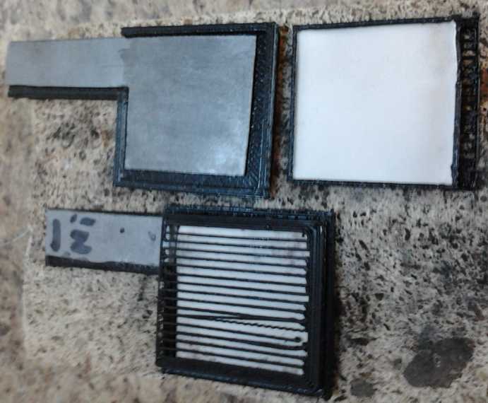
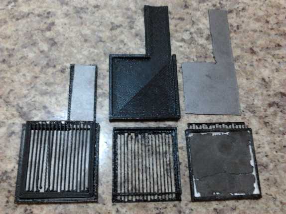
Electrode Frames - Better 'Pocket Electrode' Design
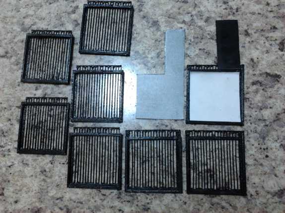 Near the
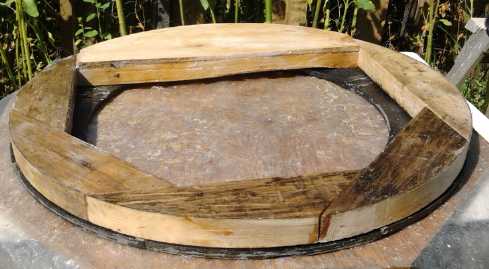
start of the month I made some plastic electrode holding frames. I kept
coming up with minor changes while printing them, and over some hours
came up with quite a
few (image to left).
Near the
start of the month I made some plastic electrode holding frames. I kept
coming up with minor changes while printing them, and over some hours
came up with quite a
few (image to left).
Then on the 6th or so I got an idea to make two part electrode frames
that fit together like a two piece
cardboard box, one's edges fitting just inside the other. The rear side
would be solid plastic (replacing separately cut ABS pieces), with the
terminal supporting tab as a piece of that. If the sides were a little
shorter than the thickness of the electrode, pressure on the faces
would clamp it together 'perfectly', and there would be little chance
anything could leak out except through the porous face - with the thick
watercolor paper covering it. A thinner briquette wouldn't have a
hollow space to expand into, and a thicker one wouldn't create gaps at
the sides. If experience shows any stuff still manages to get out the
edges, they can be glued together.
This hearkens back to nickel-iron 'pocket electrodes', but
in plastic - something I've wanted to attain for quite a while, but
only now at last found this good design for. One difference is that the
porous front face won't be strong enough to retain expanding electrode
material without bulging, so pairs of electrodes will still have to be
clamped securely together. (Even Edison made pockets of round
perforated "pencil" metal tubes so they couldn't bulge.)
On the night of the 12th I worked through some frustrations with 3D
printer quirks in designing the 'boxes', and printed 2 of each part
before 1:30 AM.
Nickel Manganese Tests
I put in a zinc strip during a load test to check
electrode voltages against. I had assumed that the manganese had been
discharging most of its energy over a few hours. Thus the rapid voltage
drops in a load test would be due to lowering Mn negode voltages, and
the drop slowed somewhere under 2 volts because the zinc conductivity
additive would start to discharge, turning the cell to Ni-Zn.
That wasn't what I was seeing with the zinc strip, so I
continued the test down to lower voltages. Now it appeared that it was
the posode that was rapidly dropping voltage during the test, until the
voltage was under about 1.6 volts. The Mn stayed about .4 volts more
negative than the zinc strip. Below about 1.6 volts, the negode started
losing voltage - much more slowly than the previous voltage drops -
while the posode steadied. I think it went from the nickel-manganate
and nickel hydroxide voltage down to the manganese dioxide reaction
voltage, and then down to the Mn2O3 voltage. When it was down to a
volt, the
negative was almost down (up?) to the zinc voltage. (But I also suspect
the zinc strip was also changing voltage over time.)
I have some ideas about this, but basically I'm not sure
what will happen. So far I'm not seeing any further improvement in the
self discharge, but I'll continue the deep discharge tests to low
voltages. They may well be making some beneficial changes, especially
in the posode.
The next test (5th. 15:00 PM) showed little improvement in
the self discharge (30': 2.518v), but my thoughts turned back to the
borax which would probably form some borohydride in the negode. I
dumped in about 1/4 teaspoon - twice what I'd put in before. Now
something came back to me: the first electrode had been slowly
improving. With more zircon (11%), the second one had started out
better, but didn't improve. I would have changed the electrolyte unless
it looked clean, which is unlikely. I don't remember adding borax the
second time. No borax, no gradual improvement!
 I note that
the little bits of white (KCl?) and green
(CuO?) stuff that were exuding from the electrode terminals grew into
fluffy crystal forests after the addition of the borax. (I've always
seen polyethylene, and glass, as hydrophobic, but somehow even the
glass marble on the lid becomes salt encrusted.) By the 8th, the cell
was definitely holding higher voltages longer at first. But over an
hour and more, it was losing considerably faster. It was as if there
were two causes of self discharge. One was decreasing, but the other
was increasing. I opened the cell.
I note that
the little bits of white (KCl?) and green
(CuO?) stuff that were exuding from the electrode terminals grew into
fluffy crystal forests after the addition of the borax. (I've always
seen polyethylene, and glass, as hydrophobic, but somehow even the
glass marble on the lid becomes salt encrusted.) By the 8th, the cell
was definitely holding higher voltages longer at first. But over an
hour and more, it was losing considerably faster. It was as if there
were two causes of self discharge. One was decreasing, but the other
was increasing. I opened the cell.
The electrolyte was black! Perhaps the same chemical
reactions that were reducing the self discharge of the negode were
contaminating the electrolyte and causing the second type of self
discharge? But this could presumably be solved by changing the
electrolyte. I put the electrode assembly in water for a while to help
dilute the electrolyte held in the electrodes, and did so. The crystal
forest on the lid quickly disintegrated in the water.
Then I realized that there was only one cable tie holding
the electrodes together instead of two. It was nearer the top, and the
bottom had swelled up and was releasing black electrode powders. This
was the last battery made before I got the 3D printer working again, so
the electrodes were merely wrapped with watercolor paper, which had
broken open again, and some PP nonwoven cloth that didn't have enough
fibers to prevent leakage. The electrode pockets are looking more and
more attractive!
I used a little more paper and 3 layers of fat
macramé cloth between them and stuffed it all together again.
But I'm starting to think more definite results might need to wait for
a new cell made with the glued 'box' pockets described above. (I only
wanted to run a test here not get into more battery making work but the
morning has gone - I was trying to work on the Electric Weel motor!)
Nickel-Nickel Cells
The nickel-manganate positive has almost double the
voltage in salty electrolyte that it would
have in
strong alkali. Choices for a really good negative side are more
difficult: iron, cadmium, zinc and metal hydride all eventually succumb
to gradual chemical changes and deteriorate, or even short out the
cell. Some other metals with good reaction voltages, eg vanadium and
chromium, have various soluble states and will rapidly dissolve.
Two especially promising metals that look like they should last
'forever' are
manganese and nickel.
The reaction voltage of manganese is so high it's hard to
make it
work, as the ongoing thread of these newsletters shows. No one else has
even got it to charge and hold a charge. I've accomplished that, but a
gradual self discharge has prevented practical cells so far.
Nickel metal has the unique attribute that it won't
oxidize
in pH 14
alkali even at a positive voltage, so it's never been considered for an
alkaline battery negative. Instead it's been used for non-corroding
current collectors -- which is the reason alkaline batteries became
popular. But (as I finally understood) it will
oxidize at any lower pH, so it can
be used as a negode in salt solution, at least with a graphite based
current
collector even if no metal works. Like Mn, Ni should last approximately
forever in a negative
electrode to make 'perpetual' cycling batteries. The chief drawbacks of
NiNi
over NiMn are higher cost and over a volt lower reaction voltage,
making cells only
around 1.1 volts nominal. On the
other hand, this voltage is so low self discharge should be no issue,
and sealed dry cells should be practical.
There's another factor: The current drives of my Ni-Mn
cells seem rather low. Whether this is just my constructions or
inherent in the chemistry is unknown at this point. It might be that
Ni-Ni would have a higher current capacity, perhaps even a much higher
drive, than Ni-Mn. This might mean that Ni-Mn would be great for low
current devices, but not for high loads such as electric transport.
Ni-Ni might turn out to
be as good as or better than nickel-metal hydride for either dry or wet
cells, and would be far easier and safer to make at home or in small
production.
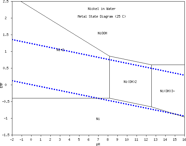 At any pH from about 8 to 12-1/2, a cell with nickel in both electrodes
should charge to about 1.25 volts and last an indefinite number of
charge-discharge cycles. (I'm not sure where the Ni(OH)3- shown at pH
13
and 14 comes from - it doesn't seem to apply in today's alkaline cells.
I also don't know how pH.es below zero and above 14 are obtained.)
At any pH from about 8 to 12-1/2, a cell with nickel in both electrodes
should charge to about 1.25 volts and last an indefinite number of
charge-discharge cycles. (I'm not sure where the Ni(OH)3- shown at pH
13
and 14 comes from - it doesn't seem to apply in today's alkaline cells.
I also don't know how pH.es below zero and above 14 are obtained.)
The first thing I did, on the night of the 3rd and the morning of the
4th, was to make the electrode frames. Hopefully these could
drastically
cut or eliminate the oozings of electrode materials into the
electrolyte.
The next question was just what form the nickel electrode
should take. With such a low reaction voltage - about .1 volts less
than hydrogen - there should be no need for overvoltage raising
ingredients.
Should there be a metal to improve conductivity, and if
so,
what? Did nickel need one, or would pure charged nickel metal itself be
plenty conductive? Zinc electrodes generally have no conductivity
additive and have very low internal resistance. I couldn't think of a
metal I'd want to use except maybe copper. If I used that, perhaps
monel would be a good form. But copper has a lot of soluble reactions.
Then again, with such a low reaction voltage, would carbon
black or graphite be suitable? And if so, what about using graphite
felt? And would a graphite foil current collector need doping?
I decided to go for nickel oxide (nano particles) for the
nickel substance, and graphite felt with a graphite foil current
conductor for the first try.
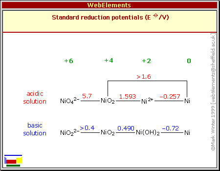 The usual battery reaction to NiOOH valence 3
isn't shown in this chart,
The usual battery reaction to NiOOH valence 3
isn't shown in this chart,
Instead its voltage of .49 is shown as going to NiO2, nor is a valence
6 shown anywhere else.
This may be more errors in the charts I was using all this time until I
discovered Pourbaix diagrams.
Nickel Negode
Working out amp-hours, pure nickel (discharging to nickel
hydroxide) would have 914 amp-hours per kilogram. This high figure
surprised me, given that nickel hydroxide as a positive is just 289
theoretically... and realistically maybe 1/3 of that. But why should
it have? Zinc is 820
and manganese is 976. Nickel is between them in atomic weight and all
of them move 2 electrons per reaction. Nickel discharged to
hydroxide in the negative side, counting the "(OH)2" mass, would be
579, or nickel oxide (NiO), my planned starting form, would be 718. If
the voltage seems low, at least that's good amp-hours! The NiO should
charge to Ni metallic nano particles and then
discharge to nickel hydroxide and never be NiO again.
It seemed there was nothing else to add unless it was a
percent or two of "vee-gum" - a bentonite clay to "glue" the briquette
together a little better. But better than what? Zinc electrodes were
flimsy, but nickel ones might be fine with nothing, and it would have
the felt anyway.
On the evening of the 4th, I put the felt in a small jar,
filled it with powder, tapped and refilled until the felt seemed
saturated. The triple felt layer was about 1.75g, and the nickel powder
in it was about 10.5g - so about 7 theoretical amp-hours. Then I
dripped in some Diesel-Kleen, Sunlight dishsoap and water and pressed
it to 10 Mg (mega-grams - tons), 625 Kg/sq.cm and left it in the press
for a while. When I took it out, unlike most electrodes it was somewhat
flexible instead of brittle. This may be from using too much liquid.
Some
oozed out in the press.
My [pottery supply store] nickel oxide was black,
indicating that it was non-stoichiometric, which means that some nickel
atoms might be at valence 3 (or 1 or 0?) rather than 2 and the crystal
structure isn't entirely regular. This is probably an advantage in
conductivity over green (stoichiometric) nickel oxide... unless it has
deleterious impurities. I chose it over my turquoise colored nickel
hydroxide also because it was more dense. I thought the fluffy
hydroxide might charge to rather loosely packed metallic particles,
reducing conductivity.
However, whatever form it starts as, it will all discharge to
hydroxide. Maybe I should go back to adding thiamine for a better size
balance between charged and discharged?
Posode (with graphite powder)
Next I pressed the posode. Since the graphite didn't
seem to be the cause of the self discharge, I used some powder with
graphite that I still had in a jar. (When I get the fine conductive
carbon black in a month or so, I think it should at least double the
current capacity over graphite powder. For now I just want an electrode
that works.) I pressed it to 8 Mg. It was only 5g of the lighter powder
in the felt, and it compressed to a thinner electrode. This is
backwards, since it needs at least 1.5 times the active material to
match the negode's amp-hours, even in theory. If it gives 1/2 an
amp-hour I'll be thrilled. Oh well. "Works" is the main point here.
Assembly
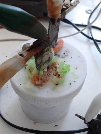
I left the electrodes to dry overnight and on the morning
of the 5th I singed them and then assembled the cell. This time I
remembered to paint the calcium hydroxide layer onto the posode current
collector sheet. I didn't however do the osmium doped acetaldehyde.
This was probably a mistake, as the initial current capacity seemed
very low and the cell had to be charged quite slowly - 30mA and it was
almost at 2 volts. This was also probably from using straight nickel
oxide with no metal in the initial negode. (Why don't I think more
often to put in zinc strip to help see which electrode is
doing what?)
 Putting both
electrodes in the little frames made the work
easy. The frame edges took the place of wrapping the paper around the
briquettes, so just little squares of paper (~41x44mm) were needed for
the active faces. These were placed in the frames in advance with one
edge folded up a bit, then the briquette dropped in. Behind each one
goes the current collector, and then a heavy piece of plastic to hold
everything stiff. A cable tie wraps it all up into one layer cake
assembly. A bit of RTV silicone glues the graphite foil terminal tab to
the plastic tab piece.
Putting both
electrodes in the little frames made the work
easy. The frame edges took the place of wrapping the paper around the
briquettes, so just little squares of paper (~41x44mm) were needed for
the active faces. These were placed in the frames in advance with one
edge folded up a bit, then the briquette dropped in. Behind each one
goes the current collector, and then a heavy piece of plastic to hold
everything stiff. A cable tie wraps it all up into one layer cake
assembly. A bit of RTV silicone glues the graphite foil terminal tab to
the plastic tab piece.
Next holes, slots, are made in the lid of the jar for the
terminal tabs. When they are pushed through, They're glued with heat
glue or RTV. If desired, a round hole is put in the lid for a filler
and inspection hole. This is covered with a small glass marble (from
Michael's Crafts store floral arrangements section). But the hole isn't
vital. The jar can be filled first, and can be unscrewed and opened,
with the electrode assembly attached to the lid, not to the jar. (Good
for changing the initial electrolyte if it gets dirty, too.) A pinhole
for emergency venting might be nice - otherwise I'm sure something will
give to release any dangerous pressure buildup without a blow-up.
Next!
After a while and the usual internal leakages of materials
- and self discharge somehow just as bad as the manganese in spite of
the much lower voltage - I gave up testing the cell. I decided to
assemble a new one using the new plastic electrode 'boxes' that would
hopefully last. On the 19th I made a briquette with monel pressed to 10
Mg - no graphite felt. It was so crumbly that I dropped it back into
the mortar for remixing, and got out the Veegum (a bentonite clay),
intending to add a few percent. On the 23rd I finally got back to it. I
added around a gram of VeeGum. (somewhere in adding and subtracting and
forgetting I managed to confuse myself as to just how much it was - .75
or 1.75g.) Considering the crumbling briquette and thinking how hard
monel is, I pressed it this time to 15 Mg instead of 10.
Before making the posode, I decided to wait a few days for
the conductive carbon black I ordered, which was to arrive just about
the end of the month. But it still hadn't by September 2nd.
Lead-Acid Battery Renewal
The second battery I renewed (of three seemingly identical
size 27 batteries) behaved rather differently from the first in the
Mazda. Of course lower voltages are to be expected from higher pH, but
they both got about the same electrolyte. They would both eventually
charge up to full voltage, but the first one, as soon as it was used,
would drop down to about 7 volts. Under load it would drop to 6, 5 or
even 4 volts, but it stayed about the same while driving several miles.
The second one only went down to 10 volts. But over about 3 miles the
voltage dropped more and more, until the voltage display was winking
out at about 2.5 volts under moderate load and it may have been going
to zero or even lower. I tried not to stress it too hard, but to drive
anywhere I kept finding it failing on the return trip.
For a while, neither of them seemed to improve markedly
over time - the first to get to higher voltages, nor the second to
either go higher or to last longer. (If it's deteriorating further it
would be no surprise.)
Finally the second one started going to higher voltages,
and one day (25th?) it stayed high longer, but I drove too far that day
(owing to a rather long detour) and it rapidly went down to nothing
again after a certain point. I stopped and disconnected it on the way
home since I was doubtless damaging it. But now the voltage (with no
load) stayed up higher longer, and on the 28th I reconnected it to see
if it
was better, the same, worse, or essentially shot. It didn't seem to
last as long. On September first, with the car having been plugged in
and no
driving the previous day, the battery started out at just 10 volts,
notably
lower than it had been doing. It dropped fairly rapidly and I had to
disconnect it again. I can only assume the pulse charger hadn't kept it
up once it got it there. It may have decided the battery was bad and
quit or
something.
It will be interesting to try the third battery, which I
haven't refilled yet.
http://www.TurquoiseEnergy.com
Victoria BC