Turquoise
Energy Ltd. News #80
September 2014 (posted October 5th)
Victoria BC
by Craig Carmichael
www.TurquoiseEnergy.com
= www.ElectricCaik.com
= www.ElectricHubcap.com
= www.ElectricWeel.com
Features:
* Unipolar 3-phase brushless
motor configuration offers greater performance and inherently
better
motor controller economy, efficiency and reliability (see bottom of
Month in Brief and or Electric Transport - Unipolar Motor
and Controller)
* Government Program for Sustainable Energy Development: Lots of
Hype, no Support (SDTC Funding Workshop & Critique - see month
in brief)
* Simple Ocean Wave Power System (originally from TENews #59 -
see month in brief)
Month In Brief
(Project Summaries)
- Solar panels: cheaper and cheaper! Get yours now because the
low prices may not last. - Electric Hubcap motor family developments -
peltier fridge notes - Sustainable Development Technology Canada (SDTC)
funding workshop at University of Victoria (UVic) & Ocean Wave
Power - Unipolar motor
& controller.
In Passing
(Miscellaneous topics, editorial comments & opinionated rants)
- Electric Transport's Effect on Power Grid - New Institutions
must have Provision for Future Growth - Pandemic: Worst Case Scenario
Video - Shoot the Messenger! - Truth on the Internet
Electric Transport - Electric
Hubcap Motor Systems
* Electric Weel project progress: body molds done, body done,
bearing holders done.
* Variable torque converter transmission
* An ultra-efficient manual transmission with flat belts?
* Unipolar Brushless Motor and Motor Controller
* Kelly 300 amp BLDC Motor Controller
Other "Green"
Electric Equipment Projects
* CNC Gardening Machine: Tools
* Aquaponics & LED Grow Lighting Project
Electricity Generating (no reports)
Electricity Storage - Turquoise Battery
Project (NiMn, NiNi), etc.
* Conductive Carbon Black Arrives (no other developments)
No Project Reports on:
Lambda
Ray Collector, Magnet motor,
Woodstove/Thermal Electricity Generator,
evacuated tube heat radiators.
Newsletters Index/Highlights: http://www.TurquoiseEnergy.com/news/index.html
Construction Manuals and information:
- Electric Hubcap Family Motors - Turquoise Motor Controllers
- Preliminary Ni-Mn, Ni-Ni Battery Making book
Products Catalog:
- Electric Hubcap 7.2 KW BLDC Pancake Motor Kit
- Electric
Caik 4.8 KW BLDC Pancake Motor Kit
- NiMH Handy Battery Sticks, 12v battery trays & Dry
Cells (cheapest NiMH
prices in Victoria BC)
- LED Light Fixtures
(Will accept BITCOIN digital currency)
...all at: http://www.TurquoiseEnergy.com/
(orders: e-mail craig@saers.com)
September in Brief
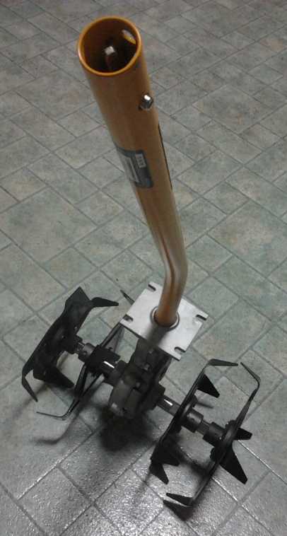 I found a
small Ryobi brand "Extend-It tools" rototiller type cultivator I figure
I can use for the
CNC gardening machine on the 4th at Home Depot building supply. A
couple of days later
I bought the electric power head for it. (Later in the month I got the
"Extend-it" 'weedeater' attachment that I think could have several
CNC gardening uses.) I'm excited by the cultivator, which if it works
well - and probably in conjunction with a couple of other tools like
something to carry off rocks and roots - could make easy work of
preparing a lawn or other unprepared or neglected plot for gardening.
With the top guard removed as shown, I think it could be dug right
under
the ground for deeper cultivation than if used by hand. If it proves
too hard to turn, some of the tines can be removed - who cares how long
the machine takes to finish the tilling?
I found a
small Ryobi brand "Extend-It tools" rototiller type cultivator I figure
I can use for the
CNC gardening machine on the 4th at Home Depot building supply. A
couple of days later
I bought the electric power head for it. (Later in the month I got the
"Extend-it" 'weedeater' attachment that I think could have several
CNC gardening uses.) I'm excited by the cultivator, which if it works
well - and probably in conjunction with a couple of other tools like
something to carry off rocks and roots - could make easy work of
preparing a lawn or other unprepared or neglected plot for gardening.
With the top guard removed as shown, I think it could be dug right
under
the ground for deeper cultivation than if used by hand. If it proves
too hard to turn, some of the tines can be removed - who cares how long
the machine takes to finish the tilling?
It's a start at answering what sort of tools might be
mounted on the CNC gardening machine. Apparently I won't have to make
them all myself after all!
After that, September developed into a month concerned
largely with several aspects
of the Electric Hubcap Motor & drive system. And I spent a
worrisome amount of money.
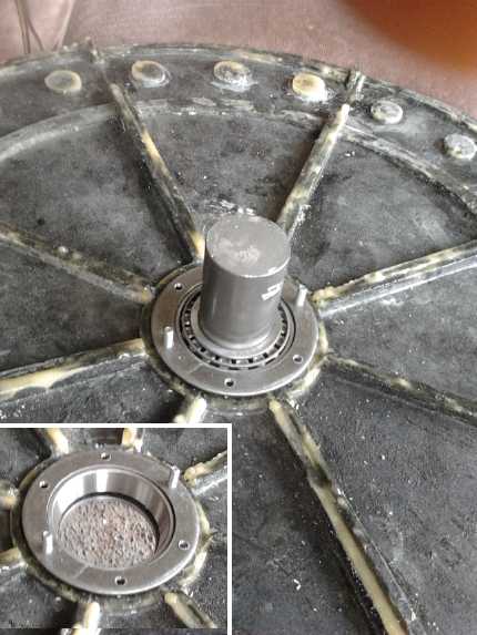
 * I made the last mold
piece and molded the 8 pieces for the rotor end
of the giant Electric Weel motor or generator. Then I did the shaft bearing holder
drill template and the holders
for one end. (The uneven thicknesses and the flatness got better.)
* I made the last mold
piece and molded the 8 pieces for the rotor end
of the giant Electric Weel motor or generator. Then I did the shaft bearing holder
drill template and the holders
for one end. (The uneven thicknesses and the flatness got better.)
* I gave more thought to implementation
of unipolar motors and motor
controllers for them, ordered electronic parts, and started designing
the unipolar motor controller circuits and circuit board. (More below.)
* I also thought about a way to make an ultra-efficient vehicle
transmission using 99% efficient flat
or poly-V belts instead of gears. There would be two or more pairs of
pulleys (think drill press pulleys, eg: small-large (start-up, low
speed);
medium-medium (city driving); & large-small (highway)), each with
its own belt. Idler wheels rotated into position using the single line
shift stick would engage the desired belt, while the other belts would
(ideally) stay loosely sprung out and not even touch their pulleys.
Such a transmission would have almost no losses, compared to the
typical 30% power loss of most manual transmissions. But when I started
trying to fit the design using cardboard pieces, there seemed
to be complications to making it for the Sprint without starting from
scratch, and besides, the variable torque converter should be
better.
 * Then I figured out a
simpler way to lay out the transmission extension for the
variable planetary gear torque converter: use short pieces of steel
rectangular tubing (2" x 3") as "stand-offs" to mount the motor to,
thus extending the effective
width
of the transmission box by 3" to avoid considerable reworking. A 3"
shaft will carry the
output of the planetary converter to the inner drive rotor of the
centrifugal clutch. This will have to hang between the ring gear and
the output shaft, rotating independently of the output shaft with a
bushing keeping it centered. (A bearing would be better but difficult
to mount with the present arrangement.) Near the end of the month I
began assembling and mounting these "stand-offs", but at a snail's pace
among other tasks.
* Then I figured out a
simpler way to lay out the transmission extension for the
variable planetary gear torque converter: use short pieces of steel
rectangular tubing (2" x 3") as "stand-offs" to mount the motor to,
thus extending the effective
width
of the transmission box by 3" to avoid considerable reworking. A 3"
shaft will carry the
output of the planetary converter to the inner drive rotor of the
centrifugal clutch. This will have to hang between the ring gear and
the output shaft, rotating independently of the output shaft with a
bushing keeping it centered. (A bearing would be better but difficult
to mount with the present arrangement.) Near the end of the month I
began assembling and mounting these "stand-offs", but at a snail's pace
among other tasks.
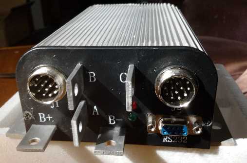 * Finally, on the 13th I
ordered a Kelly BLDC motor controller that
would put out 300 amps at 24 to 36 volts. This should allow me to test
my motors up to much higher powers than my own controllers, which I
still haven't perfected. They tend to burn out somewhere still
under 100 amps.
* Finally, on the 13th I
ordered a Kelly BLDC motor controller that
would put out 300 amps at 24 to 36 volts. This should allow me to test
my motors up to much higher powers than my own controllers, which I
still haven't perfected. They tend to burn out somewhere still
under 100 amps.
For example, 200 amps at 36 volts would be 7200 watts
(headed for 10 HP) for the 36 volt Electric Hubcap motor. That should
easily
move the Sprint car on level ground with the 4 to 1 chain reduction,
even without the torque converter.
And now I expect I won't bother perfecting my BLDC
controllers assuming
the unipolar brushless motors work out well. They use a different
controller - and
one that would inherently be cheaper to make and much more reliable.
(That by itself attracts me to the unipolar motor idea.)
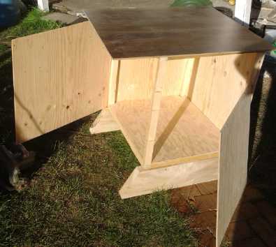 In the second week somehow I
volunteered to make a
sawdust-proof computer cabinet for the Victoria Makerspace's new CNC
router machine. I want to be in touch with this project in order to
learn more myself for setting up the CNC gardening machine. Somehow for
a week I seemed to get little else done. It seemed a bit extravagant to
put my own projects aside for a week, but I made a very nice cabinet.
In the second week somehow I
volunteered to make a
sawdust-proof computer cabinet for the Victoria Makerspace's new CNC
router machine. I want to be in touch with this project in order to
learn more myself for setting up the CNC gardening machine. Somehow for
a week I seemed to get little else done. It seemed a bit extravagant to
put my own projects aside for a week, but I made a very nice cabinet.
It ended up with a nice kitchen countertop piece for the
top and a unique arrangement of two blocks with two pins at the
front-right corner (that I thought was pretty clever!) to hold the two
easy-access doors closed. Pulling either pin releases both doors.
Unfortunately I neglected to take a picture of the completed unit.
And I have learned a few tidbits about CNC drives.
On the 14th I put another
battery in the electric Mazda
RX7 - one I had renewed when I first bought the Mazda and now belatedly
realized the lower voltages didn't mean it has a problem. The second
battery had higher voltage than the first, and started by giving about
a 3 mile range. That seemed to improve to about 4 miles over the weeks,
but I got tired of having to stop and disconnect it during longer
trips.
This "new" (3rd) one has the low voltages of the first one I tried a
month or two ago, and it seems to be giving maybe a 3 mile range
initially. I hoped that would improve, but I think I left it much too
long on charge and then discharged it too far while driving, several
times, reducing the performance instead. That seemed a pity since it
doubtless had the potential.
I decided to keep using it a while, then I thought about
cycling it with the 'pentagon' headlights as a load. Say... That's what
I did with the first battery, the one that seemed to work consistently
once it was in the car.
On the 15th the conductive carbon black for making battery
electrodes at last arrived. A big (6 L) pail was over 1/2 full of
featherweight, very conductive powder. I didn't find time to make the
electrode and put a cell together.
Also that day, just to drive the car
and cycle the battery, I went out and bought ice cream and frozen
chickenburger patties... then a very large roll of polypropylene
("landscaping") cloth for making motors, a piece of 2" x 3" steel
tubing for making the variable car transmission (my intended purchase),
and - when I found out the price - two 250 watt solar panels to mount
facing west for catching the afternoon and evening sun. It turned into
another expensive day of shopping!
The price of solar panels has dropped so fast it's hard to
realize how the economics is changing - about 30% per year. In 2010
they became cheaper per kilowatt than making new nuclear plants, and
the capacity seems to have crept up from typically 225 watts per panel
to 250. The parts for a 250 watt off-grid or grid-tie system are now in
the hundreds of dollars instead of thousands, and the payback time has
halved again - probably to under 5 years in sunny climes, and even less
where electricity is quite costly like Hawaii. I had been
waiting to hear about some discount panels being dismounted from
somewhere, but when I finally asked and heard that brand new, mint
condition panels were now 255$ (wholesale price for Turquoise Energy)
instead of 500$ I broke down and bought them. The price has to level
out now tho, since just an aluminum framed tempered glass window that
size could easily cost that much even without any solar cells in it.
Also, the low prices may not last. According to Harvey
Organ (interviewed on USAWatchdog.com) the world's
available silver stocks are dwindling rapidly owing to its use in
making solar panels and other electronic goods, jewelry and other uses,
and increasingly purchases by consumers as monetary instruments to
hedge against fiat currency collapse, especially in Asia. The Shanghai
exchange where most
of it is traded has reportedly gone from 30 million tons to 2.9 million
in a year. (The SLV and LBMA exchange traded silver funds reportedly
have only an ounce of actual silver backing every 50 to 100 claims, so
there's little actual silver to be had in the west. The prices of
silver, gold, oil and other key items are manipulated downward with
"naked shorts" paper trades by banks (that they can never deliver on)
to prevent people from noticing that the
currency is starting to lose its value month by month now more than
year
by year. So the price of silver won't rise until there's none to be
had. Then it'll
skyrocket.) Perhaps other metals can substitute, but the trend for the
next few years looks like production costs will be rising.
On the 16th I cast the last piece for the body of the
Electric
Weel generator, the rotor end cover, and epoxied the 8 pieces together.
It's taken perhaps 300$ of epoxy resin and 30-40$ of polypropylene
cloth, and headed for maybe 100 hours of labor. I can get the labor
down some, but I don't plan on building another one any time soon
(unless of course someone wants to order a kit, which will probably be
around $4000). I
also temporarily put up one of the panels on a low roof facing west and
charged the Mazda EV via solar for an hour later in the evening than
usual. Spreading the panels east to west seems much better than having
them all face south. For my roof, 2 facing east, 2 south and 2 west
might be optimum. It would be too hard to move the four already up on
the south, but as the scary high and steep roof works out, it should be
easy to put the two new ones on the west side.
On the 18th I had the bearing holders (4-1/2" washers)
reamed out to the desired inner diameter. And I started in on the
unipolar motor controller circuit design in the evening.
On the 19th I finally bit the bullet and spent the whole
day and evening on the main page for the web site. It still had a
number of deficiencies, but it was better than what was there and I
uploaded it. And the MC33035 motor controller chips arrived. I didn't
get much project work done on the weekend except to make a small table
for the aquaponics setup, but I spent a very late Sunday night (21st)
doing a few more things to fix up the web page, adding some content and
eliminating some obsolete menu links that would cause confusion. I'm
calling the short blurbs about various projects on the main page
"introductions" to the subject.
(http://www.TurquoiseEnergy.com/)
On the 20th I made a small table for the aquaponics
drain-down bed, but I didn't get much else done on the weekend.
On the 22nd the Kelly 300 amp BLDC motor controller
arrived. With the 300 amps it's rated at, the Sprint car should have
started moving on level ground even without variable torque reduction
beyond the 7 to 1 reduction from the chain drive and planetary gear.
On the 25th I made the hole drilling template for the
bearing holders for the Electric Weel, drilled one set, and mounted it
in the Weel to check the fit. It fit. I'll just buy the washers rather
than having the holders waterjet cut, as I'm only planning to make one
more, to electrify the Toyota 4runner truck, unless customers can be
found who will pay a considerable sum for kits. (That's not impossible
-- in addition to having the best, I expect I'll have virtually the
only unipolar motors and controllers being made, and they'll be an even
better combo than regular bipolar BLDC.)
The Electric Weel is an exciting project and a huge and
valuable motor or generator, but I'll be glad to have the first one
done and to move on to other things for a while before I make a second
one.
On the 24th and 26th I cut the "stand-off" 2"x3"
rectangular tube pieces, for mounting the motor away from the Sprint
transmission box to gain width for all the parts. By the 29th I had
located exact positions and drilled some mounting holes, and fit them
on.
Finally on the 25th I took the renewed battery out of the
Mazda, since its short range was keeping me from using the car much. On
the 26th, instead of buying another lead-acid, I put the other 16 volt
lithium in, and then it was up to a theoretical 140 volts. I drove 4.7
miles to buy a power adapter to charge the new battery, which seemed
well charged when I put it in. I plugged it into one of the two 'spare'
voltmeters on the dash to keep an eye on it. So now there's two 16 volt
lithiums, three 12 v NiMH.s, four size 27 lead-acid, and two size 24
lead-acid. I tried to figure out a way to replace the two smaller
lead-acids with the larger size, but couldn't find room unless I
replaced the two with just one.
On the 27th I tried out the aquaponics setup with a 12
volt "utility pump" I had purchased for 50$ because earlier I had found
that the circ pumps seemed to ooze rust. I can't say I wasn't warned in
the store about the iron pumps, but it was really rusting far faster
than I'd expected. I guess I should have sprung the extra 100$ for a
brass one. The utility pump was noisy and pumped water far faster than
was needed, and reducing the voltage to 6 or even 2.4 helped only in
degree: it was still noisy and I doubt it was made for continuous
service. It's a pump to occasionally move a lot of water fast - not
what I needed at all. Furthermore, the little fridge leaked onto the
floor when just partly filled. It didn't seem to leak when it was out
in the greenhouse. Fixing up the pipe exit gland area won't be easy.
Funding Workshop: SDTC Critique & Simple Ocean Wave Power
On the 29th I went to an all morning SDTC funding workshop
put on at the university. It's my understanding that SDTC was created
by parliament to fund prototype stage development of sustainable energy
projects where it's too late for university research
funding but too early
for private or commercial investment - the forgotten "D" of R & D.
But now they
say they won't fund ideas that are
just on paper - you have to have something built. Instead of
"prototypes" they now speak of "pilots", and instead of "inventors"
they want "entrepreneurs". That would seem to me to be a violation of
their
mandate. And they went on from there to demand "a consortium of
companies, at least one of which would be a customer for the finished
product" - hardly the scope of an entrepreneur trying to start
something. The presenter frankly admitted when questioned that an
individual, or even an individual company, had no chance of getting
funded. What? A consortium of companies is to be involved at
early stages to build prototypes where commercial or venture
capital would be unavailable? A prototype is usually built by an
individual, who may or may not contract out specific parts of the work
to others (since no one can do everything or have all the specialty
equipment to do everything).
As usual, creating a business plan and supplying mostly
one's
own money to qualify for getting just 1/3 funded are the criteria for a
successful application. Since the whole reason SDTC was created was
that no
other funding is available at the target stage, where is the applicant
supposed to come up with other 2/3 of the funding? If someone with a
renewable energy vision got that far, the efforts to get
there would be such a distraction from those required to design and
build
prototypes that the intended focus on developing a product or system
would be entirely
lost and the work sidetracked, while the money obtained would go for
office staff to maintain the corporate facade window dressing demanded.
As I've said before, inventors with an idea they wish to
pursue are almost by definition unemployed people -- otherwise they're
working for someone else on some other task and have no time to pursue
their own vision. Asking an unemployed person who's looking for funding
to create something new, to supply 2/3 of his own salary to qualify for
receiving the last 1/3, isn't a path that's likely to allow anyone to
invest their time and
put their creative talents to use. On the other hand, asking an
established corporation to come up with a grand vision for a new
sustainable energy device is equally unlikely to provide any positive
results. Sometimes a vision can drive a new enterprise. But the old
enterprise is normally commercializing some other previous vision, not
generating - or even accepting handed to them - new ones that would be
sidelines to their present business. Existing enterprises normally buy
patents to suppress new technologies that would compete with their
existing business, not to develop new products.
A rep from Schneider Electric spoke at the end to
talk about their SDTC funding experience, which helped them obtain the
money
they needed to expand into a new area of power metering. But he said
they had to have
someone work full time to fill out the forms and meet all of SDTC's
requirements in order to get funding - which was for only 1/3 of the
amount required, the company having to supply 2/3 plus the salary of
that worker. Once again, you have
to already have lots of money in order to qualify for funding, and
unless you're
after at least a million dollars it would be more work to apply than
the value of a successful application. With cash already coming in from
sales, customers waiting and a relatively developed product line, this
project really started almost at the commercialization stage, which
could have, and obviously did, find other funding. I question that they
couldn't have done it without the SDTC money.
Near the start the presenter asked how many people were
considering a
submission by SDTC's October 15th deadline, and of maybe 25 to 30
people
(at least a few of whom were actually already building interesting
clean
energy prototype designs from their own meager resources),
two raised their hands. He asked again after the presentation, and it
was down to
one! Everyone laughed.
As long as governments refuse to invest in Canada's
talented inventors and visionaries, even those with long experience and
excellent track
records and having designs in line with what the government wants made,
with
money to live on and to make prototypes - most often the
price of a modest salary plus a limited budget for parts and small
specialty parts contracts - the funding gap identified by parliament
will remain untouched, the payback from the costly funding programs
will be very limited, and the government won't
help achieve the nation's sustainable energy goals and hopes. Why
should everything start with entrepreneurs with no product? Wouldn't it
make more sense to start with talented inventors and developers who
create new product prototypes, and then link the products thus
created with talented entrepreneurs who'd like to start manufacturing
businesses, or with governments and utilities who need to build the
infrastructure that the product could enable?
As far as I can see, the tax department's SR & ED
program remains the only realistic source of funding for inventing, and
without other sources of money it's difficult to work that up into even
the amount of a decent pension - out of which must come the funding for
the projects as well as a living. And even that has just shrunk
markedly - now they say they won't even accept rental of shop and lab
space as an R & D expense.
Of course I hope to sell motors, controllers and
generators like
hotcakes, and others of my products as they mature, or, better, to have
others do that, and they'll then be worth vastly more than the time and
very
modest sums I've been able to invest in creating them and the pittance
SR & ED has invested in me to do so, but The Best is
usually developed from concept to market-ready over several years, and
for some things like ocean wave power, the entrepreneurial model just
doesn't work to start with. In addition to funding, the government has
to push the regulatory hurdles out of the way and grant foreshore
access, and say "This is to be
done." (Can anyone imagine a new entrepreneuring company, or any
company or even a consortium of companies, trying to build a dam on the
Peace River, to be connected over hundreds of kilometers of
transmission towers to the power grid, without the government behind
it? - and inventor Nicola Tesla's induction motor-generator on which
such projects are based is now century old, proven technology. And no
private entrepreneur wired the world with the internet without
government involvement. The scope is too large and the land use issues
are insurmountable.)
At the beginning someone from the university gave a brief
presentation
of the various researches going on there, and as the list went on I
realized that over the past almost 7 years I've also done work on every
one of the same project topics mentioned except metal oxide fuel cells,
along with
my other projects such as motors and controllers. Of course there's a
lot more there than that quick skim indicates, but going just by the
project topic lists one might get the impression that I do more R &
D than the university.
I think my new chemistry
batteries are generally a better bet than any fuel cells for
electricity storage.
Among the university's projects mentioned, I was doing but dropped
magnetic refrigeration, because I think improved Peltier modules under
development for
solid state refrigeration will make magnetic methods obsolete
(unless for large industrial installations) before they're even on the
market. I was familiar with the UVic work up to the point I dropped it.
I had a very different approach that I thought would work better for a
lower cost. And while I
made a nanocrystalline titanium dioxide borosilicate glaze/frit to
improve solar collector performance (for any glazed collector - PV, hot
water...), I never put it to the test or went any farther with it.
Hopefully UVic has gone much farther with their solar performance
improvement material.
An NSERC (National Science and Engineering Research
Council) rep was also there, and he mentioned they had a program to
fund a university researcher (who is probably already getting
a salary)
with 25000$ to work on solving a company's specific scientific or
technical
problems 'for 3 or 4 months', free to the company. 25000$ is more
than my annual income, but not being with a
university I'm not eligible. As a company Turquoise Energy might
perhaps contract someone else and he could rather casually be
granted 25000$ to do research for me,
but I can't get anything towards a salary for myself to do the same
research. Again no funding for inventors. - except the tax department's
SR & ED tax credit program, where I have to spend weeks on
paperwork to justify every detail in order pry what will now amount to
half the above sum out of CRA annually.
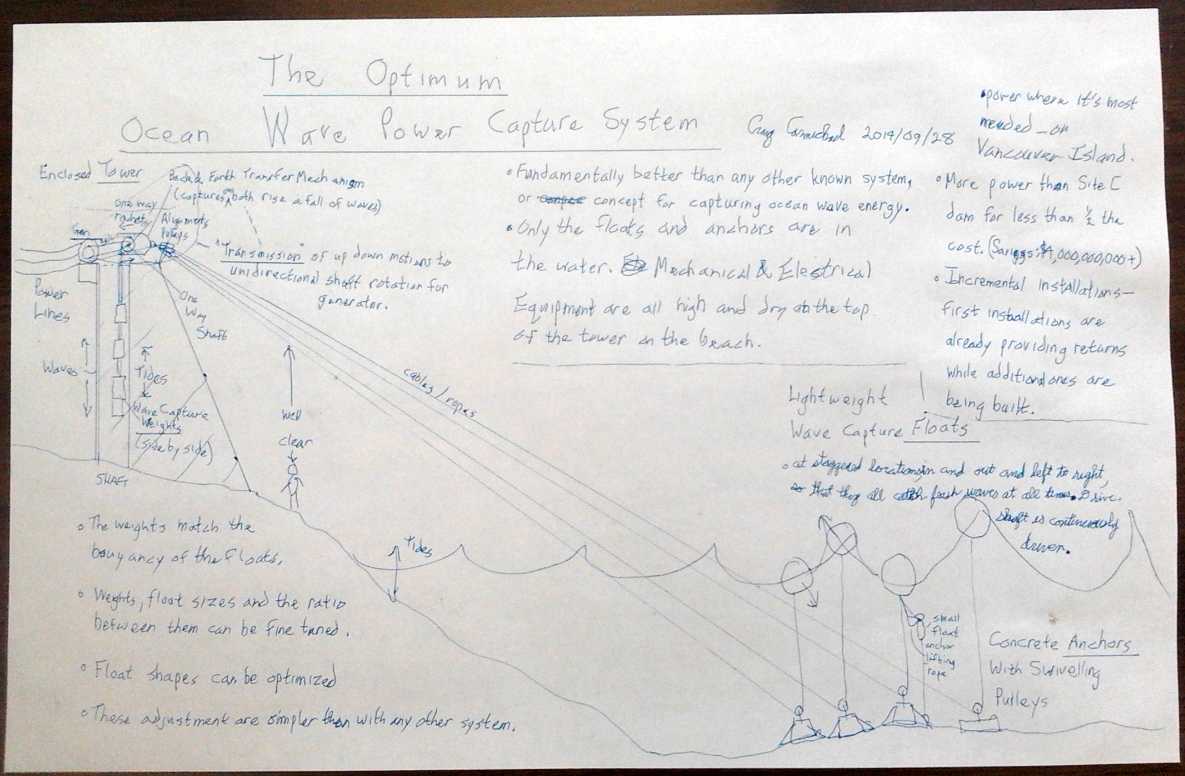
I drew a sketch of the ocean wave power system on an 11"
x 17" sheet of paper the day before (below), and I gave it to the
presenter at
the end to
take away with him. I put in as scattered bullet points, the
various technical features and the advantages and the potential, since
I knew I wouldn't have time to say much. (I
added my contact info to the sheet after I took the picture, and I also
gave him my
card.)
I pointed out in my brief moment with him that the design
had sat on the shelf for two years (I showed it in TENews#59), and I
said that if I personally had to go through all the rigamarole they had
to
get funding, it would sit for the next twenty as well. Perhaps he'll be
impressed by the potential of doing something with the generating
capacity of the Peace River Site C dam for 4 billion dollars instead of
8
billion, and figure out some way through all the BS.
But the presentation
certainly gave me the impression that there was no overriding sense of
mission, of trying to accomplish Canada's real energy goal objectives.
There was no list of "preferred project areas" that might be fast
tracked as being in line with near-term targeted government objectives.
They seemed much more interested in
their own convoluted application process and seeing that all their
arbitrary "i"s are dotted and "t"s crossed, and in running a funding
lottery for grand looking "duly diligent" but costly
"megaprojects" rather than in finding individual talent, in actual
practical and
economical designs, and in potential for achieving paradigm shifting
results. Maybe there's a big
political component to who gets funded, or maybe it's like the NRC/IRAP
program, where the
main concern appears to be how much money a university can get out of
it: Money granted to non-university applicants is, in the eyes of the
university NRC/IRAP reps,
"wasted" or even "stolen". Should a project somehow get IRAP funding
and be a success apart from the
university, it's somehow an affront to the university that someone else
did it, and with "their" stolen money. I've seen it: money for various
UVic student software projects, nothing for an accomplished inventor
trying to put an electric motor on a car wheel. Anyway those are my
impressions and experiences. "Don't bother applying." was the message
to me, and rejection the only result when I did once apply (in about
1997).
If all these people had to spend 10% as much time to
justify their own salaries annually and document how the money was
spent, of the same justifications and documentations they put other
people to, even to disburse much lesser amounts than that, they might
be more sympathetic and come up with some better and more realistic
solutions.
Simple Ocean Wave Power (better diagram)
 Germany is rapidly adopting renewable energy; here they've put
windplants
in the sea near Heliogoland Island.
Germany is rapidly adopting renewable energy; here they've put
windplants
in the sea near Heliogoland Island.
I get something of a laugh out of marine wind plant
installations like this, because there's doubtless more energy, more of
the time, in the waves beneath the towers than there is in the wind,
and an installation can be concentrated into a smaller area. There's an
episode of "Mega Builders"(?) from Discovery Channel where such a giant
windplant farm is being erected in the sea, and the waves are wreaking
havoc, trying to batter their ships and equipment to pieces while they
try to work - and that's in the calm season.
Ironically the wave power would be much
easier to install at sea than the wind towers. Just lower the anchors
with the floats attached and run the cables to the shore. Everything
else is done on shore. (Of course, a tower with multiple floats could
be
sited offshore if it was advantageous.)
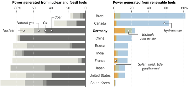 Sea Waves could add a good bit to Canada's
"renewables" side alongside "Hydropower"
Sea Waves could add a good bit to Canada's
"renewables" side alongside "Hydropower"
Time was spent towards the end of
the month ensuring that I could be self sufficient and still carry on
with the projects even if supply distributions should disrupted for
some period of time, and of course that ate into present project time.
On October 2nd Canada Revenue made their scheduled visit
to see what I was doing and ask questions. Apparently a new policy is
that rents can't be considered part of R & D expenses. That'll
knock my refund, essentially my income for my work of 2013 already six
months late, down from about 20000$ to 15000$. With only 15000$ to
claim as salary next year, the 2014 claim and refund will be still
smaller - maybe less than I spend on materials to keep the whole thing
going. A disability pension would pay more, without all the accounting
and paperwork. I may have to start collecting Canada Pension at age 60,
and it could be hard to pay down my growing debts unless I start
selling a lot of product, which has shown no sign of happening so far.
It may be that the government - probably pretty broke itself - is
trying to slash even this meager source of funding. And now they want
me to account for my activities day by day. (At least they didn't
demand hour by hour.) I'm not sure whether to make "Month in Brief"
into a daily diary or put it in a separate section. "Month in Brief"
has been getting less and less brief as time passes.
In the afternoon I refitted the lower gland for the
aquaponics tank (apartment fridge on its back), which had leaked in the
previous try, with a more solid threaded unit instead of a simple
rubber compression fitting. (Why should it be amazing to me that some
little thing like that would take two hours?) This is the one joint
that, if it leaks, will drain all the aquaponics water onto the floor.
It now occurs to me that it didn't have to be at the bottom - anywhere
underwater would have worked as long as the pump intake gets water.
From 10:30 PM I worked on this newsletter for nearly 3 hours.
On October 3rd I fitted out some more pipe and attached
the pump. Since the iron circpump had been emitting quite a lot of rust
when I tried it even for short periods, I took it apart. I thought of
trying to use the Caswell hand plating system and nickel plating it,
but I settled for scouring out the loose rust and spraying the insides
with polyurethane spray paint. Somehow, in spite of all the plastic
plumbing fittings I'd bought, whenever I went to do anything I had to
go buy some other little bit. As I generally wait to fit in such
shopping with some other trip to get more things done at the same time,
this definitely slowed things down. I bought a metal garden hose
attachment as an aerator to spray water back into the tank. Evidently a
tank full of fish can start suffocating in 20 minutes with no water
circulation and aeration. That's pretty critical. I'll have to give
thought to a separate battery and inverter, hooked to the solar PV
system, in case of a power failure.
Peltier Fridge Note: needs a defrost cycle?
When I change peltier modules to some new configuration, I
keep getting what appear to be good results with the fridge... then it
gradually deteriorates. For a while I started thinking the modules
themselves must have quite short lives.
I think what's actually happening is that water condenses
under the
peltier module and turns to frost, which builds up, pushes the module
slightly away from the copper bar, and the thermal conductivity drops.
Once pushed away a bit, there's room for even more water to get in. Ice
expansion may also be the reason I've had a couple of cracked modules,
rather than tightening the screws too hard or the assembly being hit by
anything.
This time, I turned it off a while for the ice to melt,
then retightened the clamp bolts (to the point where I was afraid it
might crack), and turned it on again. The temperature dropped from the
9.5° it had been for some while to 7° in something under a
day, which is better but I think still isn't as cold as it was when I
first installed it. It formed just a bit of ice in the tray, which it
hadn't for some time.
The solution is probably to have a short defrost cycle,
perhaps daily, allowing the copper bar to thaw, or even reversing the
voltage and having the peltier module briefly heat it up and hopefully
dry it off. That means that even if it needs to run most of the day to
keep the fridge cold, it needs that computer control I haven't made
yet. Two out of four times I've defrosted it manually I've forgotten it
all day and it got pretty warm inside.
FWIW the set of two Cui peltier modules of equal
thickness,
8.5 amps at 15 and 8 volts electrically in series (hence rated for 23
volts max on the 12 volt supply and with 212 thermocouples in series),
was the most successful setup so far, using the least amps and watts
to make the most cooling. That's the combo that froze the whole ice
tray and brought the temperature (at the cold end) down to 2° or
even lower, albeit in the winter when the kitchen itself was rather
cold. I'm still looking for economical
peltier modules to get a 20-24 max volts rating instead of the pricey
Cui modules from Digikey, but it's very hard to find Peltiers with any
construction
besides 15 volts/127 thermocouples.
The Unipolar Motor and Motor Controller
The 3-phase unipolar motor is similar to the usual BLDC
motor, but all the rotor magnets face the same way: instead of
N-S-N-S-N-S- it's N-N-N-N-N-N- (6 magnet poles for 9 coils). Bedini
claimed to get more energy out of his single phase version than he put
in, and I think the focus on this claim obscured another important
detail: It would appear that this unusual, non-intuitive configuration
is actually better for brushless motors with solid state controllers.
It has several advantages over the regular bipolar one.
First, the three phases are driven separately and in only
one direction, the "Y point" now being connected to the B+ supply by a
fourth wire. One phase is driven at a time in a three step sequence,
the same as the bottom half of the usual 6 step bipolar sequence. When
"magnet 1" gets past the phase "A" coil, "A" turns on to repel it. As
it approaches "B", A turns off, but at this point "magnet 2" has now
passed "C", and "C" turns on to repel it. As "magnet 2" approaches "A"
again, "C" turns off, but now magnet 1 has passed "B" and "B" turns on
to repel it. As the coils are only energized to repel rotor magnets,
not to attract them, the core iron isn't driven repeatedly through its
zero point of magnetic hysteresis, so iron losses are reduced. (Not
that Electric Hubcap motors have significant iron losses anyway.) The
iron in the unenergized coil cores attracts the magnets naturally as
they approach, helping to pull the motor through some points of
rotation with less torque ripple.
But the biggest advantage is in the solid state motor
controller. Since it only has to drive the coils in one direction, the
common 3-phase "H" bridge isn't required. Only low side drivers are
used. It's probably the only motor that can be run both directions
without a bridge circuit in the controller, the direction being
reversed by reversing the drive sequence (which is done simply by
inverting the rotation sensor signals). This does several things:
1. Eliminating the high side drivers reduces the cost of the controller.
2. It cuts the internal heat and energy loss of the controller in half.
3. When magnets are being pulled toward unenergized coils, those coils
generate electricity, which (according to Bedini) can be utilized.
4. Since any voltage generated by the coils (including the coil
turn-off decay voltage as well as the above) is reverse polarity and
hence always goes above the B+ voltage that the other end of the coil
is attached to, it can be fed into batteries to charge them. (But how
to
charge the batteries that are driving the motor isn't
entirely clear so far since these coil voltages aren't referenced to
B-.)
5. No high-side floating supply charge pumps with their complications
are required.
6. Glitches can't short the B+ supply to ground, which condition
usually blows
mosfets or the entire controller.
7. The control chip and other circuitry is less likely to blow even if
a mosfet(s) blows (especially if B+ is below the voltage rating of the
controller chip such as the 40 volt MC33035), so repairs are more
likely to be limited to
replacement of the blown transistors... which are less likely to blow
in the first place.
In Passing
(Miscellaneous topics, editorial comments & opinionated rants)
Yikes! I'm actually embarrassed that I've written all the
stuff and vented all the opinions below! Anyway, I wrote them and here
they are.
Electric Transport's Effect on Power Grid
Here's a link to an article by Guy Dauncey, who started
the BC Sustainable Energy Association some years ago. He goes
into figures about how much load mass adoption of electric transport
(EV cars) would add to the power grid... and it's really not a lot
extra: around 12%. Certainly nothing like detractors of electric
transport would have us believe. I was once told "50% more" by an
engineer. There are lots of ways to generate or save that much
electricity and more... like Solar PV panels, wind power and LED
lighting.
www.bcsea.org/blog/guy-dauncey/2014/07/25/could-bc-become-100-renewable-energy-region
?
New Institutions Must Have Provision for Future Growth
In viewing all the many man-made horrors and travesties
occurring around the world, we must remember that the basic problem is
that we haven't evolved solutions, systems that prevent such things
from
occurring. We have antiquated and increasingly unworkable democratic
systems that have no provision for growth, for evolving to suit
the needs of
advancing civilization. These have been increasingly "hacked into" by
corrupt special interests to bend public decisions to suit their ends.
(It's been said that hardly a US federal law has been passed in decades
except to benefit some corporate interest or other.) And restrictive
laws are rarely rescinded, increasingly hemming people in and
destroying individual freedom
of action. One can hardly do anything without technically breaking some
law or other. What's wrong? There are many ways to look at it.
From one perspective, there are systemic problems with the
setup of governing institutions. Many countries such as Canada still
haven't separated
their executive and legislative branches of government, making both
branches somewhat dysfunctional.
The "illiterate's X" single ballot voting system is far
more unfair than is generally realized. It promotes and empowers
partisan political groupings ("political parties") ahead of talented
individuals, even when no "party" has more than time-worn rhetoric to
offer.
With only party candidates really being electable, anyone who would
hold office spends a political career trying to work his way through
and up a party hierarchy -- years during which he can't present his
vision to the legislature, and in which he is open to influence and
compromise by the corrupt. He must cast aside his ideals to finally get
to where he wanted to be years previously, by doing their bidding and
thus gaining their support and party endorsement. A legislature is
supposed to be where ideas are proposed and debated and decisions made,
by a representative cross section of the electors, not a bunch of yes
men to rubber stamp decisions really taken elsewhere behind closed
doors.
Simply ranking the choices 1, 2, 3 on the very same ballot
and recounting until one choice has over 50% (which gives the same
result as running multiple "X" ballots) would solve that problem at a
stroke - provided the executive and legislative branches are separate.
If individuals were ascendant over political "parties", we
could start electing lawyers who would fine tune the system, doctors
who would really care about people, and inventors and visionaries who
might have ideas
for better systems.
And we concentrate far too much power in the hands
of a single individual, who then virtually dictates what will happen,
and nothing happens if it's not on his personal agenda. And when that
one person is given carte blanche immunity from regular law
he is in effect invited to commit crimes and to force the nation to
obey him in committing those crimes. If anyone should be bound strictly
to the law and be subject to checks and potential swift arrest for
violations, it is the chief executive. The legislature also should
specifically have the power by majority vote to immediately arrest the
chief executive even without a judicial ruling, since leaving him in
power while such a matter is under discussion is to invite him to
dissolve the legislature as Hitler did, or manipulate it into
submission.
A legislature shouldn't try to run things - it's a place
for debate - but executive governing functions somehow need to be split
up more - more functions should be delegated without having to refer
them to the chief executive except in unusual circumstances.
Compounding the problem, there's generally no effective
provision anywhere for citizens to initiate referendums, where the
public's will can be clearly made known. The US statewide initiatives
are an excellent step in this direction, the most promising political
advance in my lifetime, and in some US states the
public has caused laws to be passed or rescinded that no "political
party" would have sponsored. This needs to be extended to the federal
level as well as local, and to every country.
And obviously we now have the internet, which could make
casting votes simple and cheap, which ought to be opening up new
opportunities for social progress and institutional change at the
governance level. The Department of Progress which I have
proposed would be charged with looking at ideas that are presented from
any source, testing them at lower levels (municipal, state) if
feasible, and presenting worthy
improvements for legislative enactment.
From another perspective, people today seem socially
uncaring and too much wrapped up in their own little affairs. Why?
Partly because the corrupt or overgrown institutions sponging off the
productive require that so much of the day
be spent working to make ends meet. For many, getting up at the crack
of dawn
has been replaced by getting up while it's still dark out, and then
making a long drive to work. What other reason but economic slavery can
there be for people, now both men and women, to work longer hours today
than decades ago, in spite of all the labor saving devices that have
been
invented over this time? People are either working too long hours or
they're unemployed. Where's the balance?
The ancient but
still extant (last I heard) British
law of Attainder, in effect the right of parliament to vote to seize
the
'attainted' properties of someone who owns far too much (on pain of
being beheaded and the property seized anyway), needs to be generally
applied. There is only so much it's
reasonable for a person (or any entity) to have, and equality
needs
to be applied, by confiscation if necessary. When one person owns four
houses in a town, three people have to rent instead of owning. When 1%
own half of a country and have 1/2 the national
income, the other 99% is immensely impoverished. No such situation
should ever be allowed to develop.
But partly the populace allows
themselves to be
diverted by entertainment media... this is again fed by the fact that
they are too tired after work to do much fresh thinking or acting. And
partly they are too often overmaterialistic and overextend themselves
to attain
material goods beyond what they really need, and keep
themselves working those long hours to pay for it all.
From another perspective, our educational institutions
don't seem to teach much on the subject of how things are run, and so
ideas for how they might be run better aren't getting into young minds.
Finance, economics and politics, subjects that affect our lives
so greatly, aren't taught at any basic level. In fact, corrupt
interests see to it that they are left off the curriculum. In the USA,
certain "foundations" (Ford, Carnegie and others) worked for decades,
successfully, to prevent the
US constitution from being taught in schools. Thus the social ferment
that should lead to such better institutions and methods as mentioned
above isn't present in the population. Education is the only path to
real individual and social progress. Let the population be enhanced
with knowledge and thinking skills instead of "dumbed down". Let youth
understand the ponzi scheme financial system and problems with other
institutions to help them invent better institutions. Let the three
core values: quality of life, provision for growth,
and equality, be inculcated in
the next generation and institutions be judged by them.
But many people do have a sense that something is
wrong, and that their governments and societies are out of control. The
Basques and Catalonia have long desired to separate from Spain, Quebec
almost voted to separate from Canada quite a few years ago, and
Scotland has just had a similar referendum to Quebec's again with
evenly split results. Ukraine and the middle east are in turmoil. Lots
of separatists are elected to the European parliament, and over 1/5 of
Americans now think that having their state peacefully secede from the
union might possibly be a good idea.
Many people think shrinking the administrated area will
render the government more responsive and accessible to their needs.
But all these splintering
movements, even if fully and peacefully achieved, will solve nothing
unless the structure of the new government is set up along lines that
grant power to the people and fully engage them in decision making
processes - such as those presented above. Advancing the structures is
a major key to fixing things, with or without breaking existing
administrative units into smaller ones. Let the advance be the key, and
let the governing institutions of the whole country advance on pain of
otherwise having a break up and seeing the splinter group be better and
its citizens happier, healthier and better off than those in the main
body. Then either way there's progress.
Pandemic: Worst Case Scenario
I watched a long documentary including a movie that
illustrated the points made on youtube called SHTF - After
Armageddon . It paints a bleak picture of the world after an
epidemic wipes out a large portion of the population all at once. The
sequence I think is more likely is the economic deterioration (well
underway now), the global financial collapse (on the verge) followed by
breakdown of distribution networks, and hunger and famine which will
finally lead to epidemics (plural) and a more gradual population
collapse. (On the other hand, Ebola is looking very scary!)
I think it's exaggerated. But it does say it's a "worst
case scenario". I don't think the power, water,
phones and internet will stay down too long if they are lost and that
we'll go back to 1800's conditions and horses for decades or longer.
But then, it focused on
Los Angeles, which, with desert all around, could indeed be a terrible
place to be when food distribution is interrupted. It opened my eyes to
some of the problems, chaotic conditions and long term changes that are
likely to occur. They also missed some fairly obvious or new individual
solutions such as travelling by bicycles (electric or not, they give
essential evacuation or migration mobility without gasoline), electric
machines for farming like the CNC
gardening/farming machine, and aquaponics.
It may well be that national and even state and regional
government will break down and there'll be a temporary return to local
governmental conditions, as portrayed. If so I'd like to see that grow
rapidly on
Vancouver island into a modern type of island-wide government based on
all the new principles, and then a restoration of the rail service for
a basic island-wide food & trade distribution system, even if only
by using an old steam locomotive from the logging museum until new
lightweight electric cars can be made and the track electrified or with
'free energy' devices on board for power. (If the movie is at all
accurate they may need armed guards
on board for a while in order to travel safely!) But it may prove
necessary for a time to ship cargo by sailboats, which will also be the
obvious means for shipping to and from the mainland.
Unions of such new local or regional governments may unite
or upstep
the remnants of larger state/province and national governments along
the
lines of the new principles and the three core values, and there will
be - already is - celestial help in helping people educate themselves
about how to achieve progress along these lines.
Shoot the Messenger! - Truth on the Internet
If "ISIS" is beheading American journalists, they would
seem to be in harmony with the US government. 'The messenger' is being
killed, discredited, jailed or otherwise
shut up whenever he or she dares try to bring a message to the public
that isn't
what a government wants the public to hear. In the USA only the few
approved propaganda networks have unfettered access to the public to
keep them in blissful ignorance of true states of affairs financial,
economic, and political. But Washington isn't alone. I saw for
example on the Al Jazeera website a plea to Egypt to release their
reporters from Egyptian jail with the phrase "Journalism isn't
terrorism.", and two RT reporters were thrown in jail for a while in
the Ukraine. On sufficient protests they were released without comment.
Canada has forbidden its scientists from speaking to the
public who fund them and for whom they work without prior approval,
just
"so that the minister of science doesn't have to read something
unexpected in the morning paper." Of course, this means a fight with
the bureaucracy for which scientists have no stomach, and long delayed
approvals, in order to convey every little piece of news and
interesting - or important - or urgent - discovery or event.
It is said that in war, the first casualty is truth. False
flag events, false accusations, misrepresentation and inflammatory
rhetoric show this is already true before the war starts. But
governments no longer have a monopoly on public communications. Those
who want to find out what's really going on now go to the internet: to
youtube, RT, Aljazeera and a host of private sources and specific news
and opinion websites. In addition to scores of journalists interviewing
various experts (especially economists and financial specialists)
telling quite different stories
than those the 'major media' focus on, one can find for example Putin's
speeches and interviews as easily as Obama's, and decide for themself
by the stark contrast who is a militaristic aggressor and who is
working for freedom, peace, dialogue and due process of international
law. (I suppose Assad is there too. Who's actually heard his side of
the story?)
Electric
Hubcap Motor Systems - Electric Transport
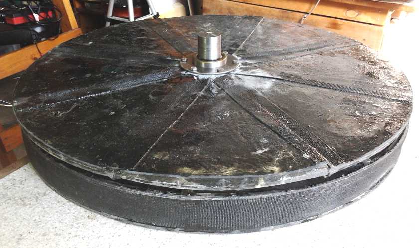
Electric Weel Motor-generator
Project
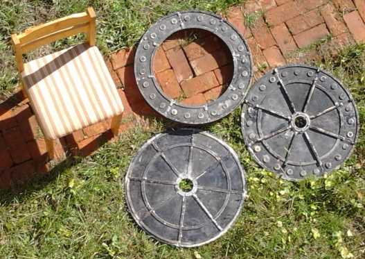
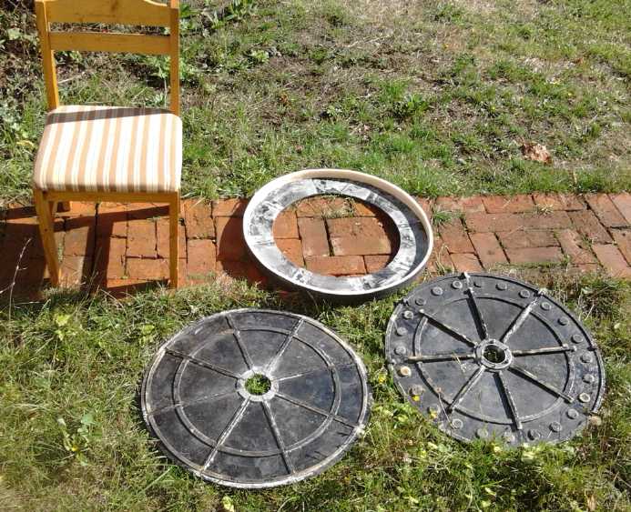 The 28" O.D. Weel Motor/Generator body pieces
with a chair for size comparison
The 28" O.D. Weel Motor/Generator body pieces
with a chair for size comparison
Put together (with a few coil cores for the spacing)
On the 3rd I wrote the G-code,
tested it with a few dry
runs on the CNC drill-router, and then routed out the lower mold piece
for making the rotor end
cover. (This is the "end bell" in traditional motor terms, but it's a
flat plate.) Again the G-code was
mostly cut and paste, from the stator end cover, but there were a few
new points of that nasty trigonometry for cutting the arcs, where
the radius of the router bit (1/4") has to be accounted for in two
dimensions. I'm sure there's modern software to do this
automatically. I decided I should help set up the new Makerspace CNC
machine and learn more in the process, especially about stepper motor
drivers and modern CNC
related software that they've probably all read up on.
After that there was cleaning it up, drilling and
threading the bolt holes to hold the upper piece on, and waxing it so
the workpiece would come out easily. I keep thinking there must be
spray wax, but I never could find any, so I end up brushing on a rather
thick and uneven layer of parafin, melted on the stove.
On the 7th I finally made two sections of the rotor end cover
with the
new mold, and another on the 8th. (On a small motor, three moldings is
the whole motor body except the rotor compartment rim. This is
looking like a great motor or generator, but whether it's really
practical may just depend on people being willing to pay several
thousand dollars for one, or on them ordering their own molds instead
of the actual bodies, and molding their own bodies on their own time.)
I had decided last month that the parts needed more epoxy
to polypropylene cloth, partly because some were a little dry, and
partly because I was noticing at various times that they had more flex
to them
than was probably desirable. Since the epoxy by itself is pretty stiff,
a little more should help.
Mixing 5 parts epoxy to 1 of PP cloth (by weight) I found
that more epoxy oozed out of the mold, probably not changing the final
ratio very much. I've always squeezed the mold parts very tightly
together with the C-clamps. For part #4 and probably on, I decided to
clamp the part less strongly - just enough to be sure the air was
squeezed out of it. The last three in particular (14th, 15th &
16th) were thicker and indeed seemed better.
On the 17th or 18th
I had the bearing holders, 4-1/2"
diameter washers, reamed out to the required inside diameters at AGO.
Then I found that the Victoria Makerspace lathe has a larger 3-jaw
chuck than mine and I could probably do it there next time.
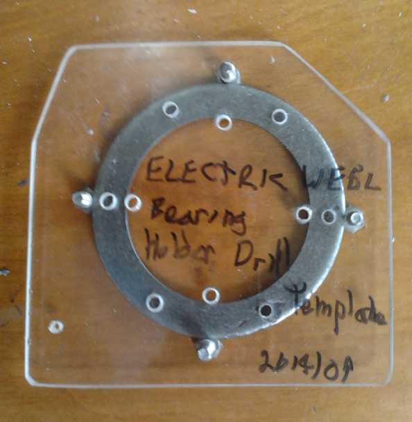 On the 25th I did the hole drilling template to drill the
6 bolt holes in these bearing holders to mount them in the motor body,
and I drilled out the two pieces and the body with it. Then I expanded
the outer and body holes to 1/4" and threaded the inner holes for 1/4"
NC bolts (1.5" long with locking nuts), and mounted one bearing end
temporarily to check the result. The customer did the other one and we
both did some of the spray painting of the body, finishing a couple of
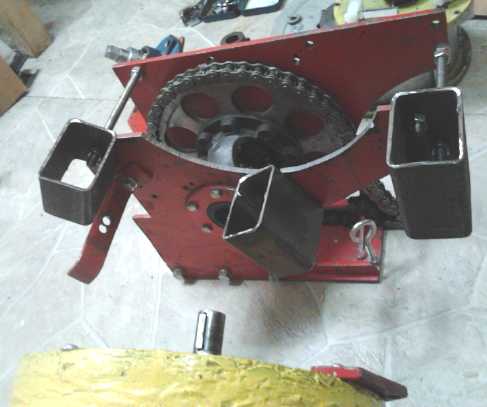
days into October. I also helped him with a piece for a chain drive
sprocket for transferring the 'paddle wheel' turbine rotation of the
floating hydro power machine to the generator. After the bearing
holders are galvanized and painted, and the holes drilled for the body
case bolts, the body of the Weel generator will be complete. (The case
bolts will need a CNC cut drill template.)
On the 25th I did the hole drilling template to drill the
6 bolt holes in these bearing holders to mount them in the motor body,
and I drilled out the two pieces and the body with it. Then I expanded
the outer and body holes to 1/4" and threaded the inner holes for 1/4"
NC bolts (1.5" long with locking nuts), and mounted one bearing end
temporarily to check the result. The customer did the other one and we
both did some of the spray painting of the body, finishing a couple of
days into October. I also helped him with a piece for a chain drive
sprocket for transferring the 'paddle wheel' turbine rotation of the
floating hydro power machine to the generator. After the bearing
holders are galvanized and painted, and the holes drilled for the body
case bolts, the body of the Weel generator will be complete. (The case
bolts will need a CNC cut drill template.)
Planetary Gear
with Clutch Torque Converter Transmission Project
At one point, for a few days, I thought again about doing
a
manual transmission with flat belts. It would still be 'ultra
efficient'. But on closer examination, it looked more difficult to
build than anticipated. I leave my ideas for it written up in the next
topic below.
As I considered that, I suddenly thought that instead of
making the transmission box
itself wider (wider is necessary whatever I build) I could just get a
couple of
short pieces of 1.5" x 3" square steel tubing, bolt them solidly to the
outside
of the box, and put some bolts through the other side for the motor to
bolt onto. The motor mounted on the tubing "stand-offs" is then 3"
farther from the
far end. This extra width provides for putting a 3" shaft from the
planetary
gear output to hold the input rotor for the centrifugal clutch. It
should be just the right width. (Or the
tubing could be any size from 1" to 3" as required to link some
'regular' sort of automotive clutch.)
To repeat here, the components for the variable torque converter
transmission are:
- motor.
- planetary gear (or other three-element gear that would do the same
thing(?))
- A mechanism controlled by the driver to implement controlled slipping
of one of the gear
elements, making the ratio between the other two
variable. This is the 10" pulley on the planets assembly with 3/4"
polypropylene rope looped around it and connected
to the original automatic transmission shift lever to tension it.
- a clutch: either some sort of manual clutch or (hopefully) the new
large, low RPM
centrifugal clutch.
- flat or poly-V belt, or chain drive (as-is), to the original
differential and
drive shafts.
The clutch is necessary because it seems (from my trials
in 2012) that the variable planetary gear only starts working and
giving the variable ratios as expected once all three gear elements are
in motion, which can't be done if one is connected to the wheels and
the car is stopped. All I can think of for the reason for this is it's
something like a "divide by zero error" when one element is stopped.
Whatever the problem is, it shows no sign of working until the car is
moving, and then it does and the car will continue slowly moving with
very little power. (I found a September 2012 video of the best example
of this sitting forgotten on a video recorder. With probably under 1 KW
of motor power the car went a few feet over rough lawn including a bit
of a rise into the shed. I should upload it for viewing!)
The clutch could possibly be eliminated by instead
putting a
large flywheel on the motor shaft, to store enough energy that the
revved up motor can get the car
to start moving while it slows, without the
variable torque conversion, by applying tension to the slipping element
once the
motor is spinning well. But this is probably harder to operate.
I had the major things made except the short shaft and the square tube
motor
mountings. I'd also have to redo the mechanism for slipping the
planetary ring gear. The linkages won't fit where they did before
because it's
been moved
over 3", and from inside the box to hanging over the outside.
Sometime in the 3rd week I got some 2" x 3" rather heavy
rectangular steel tube. (close enough to 1.5" x 3" - or maybe better!)
I cut three short lengths of it
(about 3") for a 3 point 'stand-off' motor mounting. I started with a
metal cutting abrasive blade on the radial arm saw, because it makes
straight cuts and because I saw the guy cut my piece of tube with a
big, high RPM circular abrasive blade. But his must have had a lot more
horsepower behind it, or something non-obvious that was different from
my setup. I very slowly cut the first piece off on the 23rd, and part
of the second piece on the 26th, and finally I gave up and used the
angle grinder with a zip disk. It may not make very straight cuts, but
there's no comparison in cutting speed and I was wasting my time. I was
soon done the second piece and the third. I got things lined up and
drilled some holes on the 28th, mounting two of them. I didn't seem to
find much time to get things done.
An
Ultra-Efficient
Manual Transmission Project?
As I've said, I think I've figured out the components for
the variable torque converter transmission. Notwithstanding that,
earlier I
wasn't entirely sure of all the major construction details to make it
all work
effectively, and I'm still worried about lubricating the planetary gear
if I
do get it on the road, and perhaps heating of the slipping element. So
I thought to finally get the Sprint on the road I'd simply buy a
regular, lossy transmission at an auto wrecker. But with the car having
been an automatic transmission model, there are big differences to the
mountings, and after I got the transmission I realized I'm still
missing some clutch parts. And besides, it just wouldn't have the sort
of range the ultra-efficient transmission would give. Why would I want
another vehicle like the short range Mazda?
Then I thought the transmission might still have, in all
those rotating and counter-rotating gears, some gears that might do the
job of the planetary gear in a mechanically better way. But too much
was hidden away inside, and when I tried to disassemble it, I couldn't
get one of the end bearings off, and being unable to get it off, I
was unable to proceed. I have bearing pullers (which got one stubborn
one off), but I suppose they
heated the bearings up and expanded the metal when put them on, and so
they're extremely difficult to get off - even with heat since one
can't now heat the bearing without heating the shaft. (Hmm... maybe I
can cut it off with the angle grinder? I didn't think of that at the
time.)
So I thought about another plan entirely. Flat belts or
poly-V belts have very low losses. Flat belts are said to be 99%
efficient. One could make an "ultra efficient" transmission where flat
or poly-V belts are selectively pushed against their pulleys by an
outside idler pulley. They might be just stiff enough that if not
engaged, and with a proper shroud, they could mildly spring open and be
entirely or virtually
out of contact with their pulleys. A different set of pulleys with a
different idler would actuate each "gear", a small pulley driving a
large one for a low gear and a large one driving a small one for a high
gear. A single lever such as an automatic transmission lever would
press the different idlers against the belts depending on its position,
with the idlers offset at different angles from a shaft pivotted by the
lever.
My plan for making this was to have:
- The top of the transmission 'box' widened out to 10 or 12" to
accommodate longer shafts.
- a long motor shaft with the first set of three flat belt pulleys,
with a
third bearing at the far end wall.
- a second shaft parallel to the first, with the other three pulleys on
it, about 10" away. A bearing at each end. (Think of a drill press here
with triple or more pulleys for different speeds.)
- The second shaft would also have the chain drive to the car's
original differential and drive shafts (as is), with about a 3 to 1
reduction ratio. A rather heavy belt drive could also be used. This
would be the most efficient and also eliminate chain lubrication
concerns.
- A third parallel shaft, connected to the shift lever, would hold the
three idler pulleys or 'sheaves'. (The idlers might need to have some
springyness to allow for belt variation and stretching.)
The car would thus have three speeds, low for getting
moving (0-30 Km/Hr), medium for town speeds (eg 20-70 Km/Hr), and high
for highway speeds (60 Km/Hr up). Reverse will hopefully be
accomplished by just running the motor backwards in low, although the
idler would ideally be on the other side of the pulleys for reverse.
(I'd make the unit with room to put one there if required, if possible.)
Note that if the final chain drive has a 3 to 1 reduction,
the transmission belts only see 1/3 of the final torque, of course at 3
times higher speeds. The chain drive ratio can be adjusted without
changing the flat belt pulleys: decreased to as low as 2 to 1 if it
works out better, or increased to 4 to 1 if necessary.
Also note that a gentle clutch action is accomplished as
belts disengage and engage when going between speeds, and this might be
used manually from a stop if necessary to help get the vehicle moving,
eg, on a steep hill.
This plan seems pretty straightforward, so hopefully one
wouldn't spend years at it.
On the 7th I put the transmission box in the car to eye
things up.
I wasn't sure how it was going to go or where things would fit
together, then I got the idea to make cardboard templates and make sure
everything fit together. Much easier to make those and then do another
one when changes are required than to start by cutting and welding
steel, and then discovering things don't fit the way you thought!
In fact, they didn't fit the way I had intended, to the
point where it began to look more complicated again. With the motor in
front, the idler pulleys would have to be underneath where there was no
room for them, instead of on top where I wanted them and where there
was
lots of room. If the motor was at the back, the idlers would be on top,
but that would change
everything else.
Once again I started reconsidering the whole thing. Maybe
the variable torque converter, in addition to being the best, would be
no harder to mount. I reverted to that and almost immediately thought
of the above mentioned square tubing motor mount "stand-offs" idea,
that suddenly made the variable converter probably the easier to do.
Unipolar Motor
& Controller
Motor: convert one
To convert a 'regular' Electric Hubcap type BLDC motor
to unipolar requires a new magnet rotor with a unipolar configuration,
attaching the "Y" point of the coils with a fourth conductor to the
battery voltage (B+), and desirably, replacement of the hall magnet
sensors with optical sensors. (Hall sensors could still work, but
without definite magnet polarity reversals where the transition is
exactly
between two magnets, to get N-S transitions at the right places would
be tricky. They'd have to be placed at some exact and unknown points
that could only be located (at least by me) by moving them around and
observing the transition points as the rotor is turned by hand and
estimating whether the points seem even. Those
points are unlikely to be at convenient mounting points.)
It occurs to me to put two projects together: I want to
re-do the Electric Caik rotor in the outboard with the new
PP-strapping-thru-slot magnet fastening system, expecting to make the
motor
safe for at least 3000 RPM instead of 2000. If I do a new rotor, I
could
also make
it with unipolar magnets and try out the unipolar system with it.
The usual 3 coils per 2 magnets configuration
seems to apply. But if the magnet poles are each made of two magnets
and all the magnets have equal spacing, there'll be 8 poles of one
magnet each instead, and a ratio of 4 magnets per 3 coils, or in other
words N-N-S-S-N-N-S-S- can be four opposite poles, but N-N-N-N-N-N-N-N-
with the same eight evenly spaced magnets, is eight like poles instead
of four. Doubtless that won't work. The magnets either have to be
bunched into pairs, or only 4 magnets should be installed. Perhaps this
is a place for the larger 2" x 2" supermagnets?
One potential concern about unipolar motors is that there
might be considerable torque ripple, in particular, segments of
rotation with substantially less than full torque. But this concern
pertains mainly to the ability of the motor to start turning under
load, and an outboard's load starts at zero and increases with speed.
If the car transmission has a clutch, that is also not a concern there.
In the bicycle the rider can push off or peddle to get started, so it's
not a problem there either. And on further consideration the ripple may
not be as pronounced as I was at first thinking. Some coil/phase is
always on at all points
of rotation, and where the repulsion is weakest, the magnet is most
strongly attracted to the core of the next coil. Magnet configuration
counts too. The larger magnets will probably make it smoother.
It may also be desirable to change the coil windings, or
else reduce the battery power voltage, since each phase now gets the
entire battery voltage instead of 1/2 of it. (because two phases were
in
series through the "Y" point. Now that's tied to B+). A 3-step sequence
replaces the 6-step
sequence, but it's with exactly the same low-side activations.
With, eg, a lowered 24 volts to the coils of each
phase from a
24 volt supply instead of 18 volts with a 36 volt supply, to get the
same power of 7200 watts will require 300 battery amps instead of 200.
One might also consider motor coil resistance to be halved, counting
any given phase to B+ instead of across two phases. Batteries can be
increased in amp-hours capacity or more
cells/batteries can be put in parallel. After all, 24 volts can be
obtained from just two 12 volt batteries or four 6 volt 'golf cart'
batteries, which overall battery capacity will have to be multiplied to
give good vehicle range anyway.
To use higher voltage, I could probably fit 30 turns (3
layers) of the #11 wire
on each coil instead of 21 without making the coils too bulky -- except
maybe for the Caik motor, where things are very tight. There the wire
gauge might have to be reduced. For existing motors the lower voltage,
higher current option seems attractive unless the back EMF lowers the
maximum RPM too much.
Of course, there's a couple more small complications: It
needs a different motor controller, and the hall effect magnet
polarity sensors will best be replaced by optical sensors.
Unipolar Motor Controller
Thinking back to
the old MC33033 chip that I used a few years ago in my first fairly
successful motor controllers, its big drawback - aside from production
having reportedly (by Digikey)
been cancelled - is that it has no proper high side N-channel MOS gate
drivers. But with a unipolar motor, only low side drivers are needed. And evidently only the DIP type package was
canceled, not the whole chip. Mini-dip surface mount versions are still
available. I much preferred the socketable DIP.s, but if reliability of
the controller is excellent that may not be of real concern. On
checking the datasheets, the MC33035 with four more pins
(24 vs 20) has a "fault" output, which could probably be used to
terminate and restart each 'PWM' cycle 10-50 uSec after overcurrent is
detected, to enable the improved variable frequency 'CRM' current ramp
modulation, or some hybrid of CRM and PWM, instead of fixed frequency
PWM.
With one side of each coil tied to B+ and the other side
only driven low, the unipolar controller may be unique in that it
doesn't need driver bridges to run brushless motors, and even more
uniquely, it can drive the motor both forward and reverse without them.
Three-phase bridges inherently have the possibility of shorting battery
power to ground through any one of the three legs, burning out the
mosfets and other driver components. So, however reliable typical BLDC
controllers can be made, these will be intrinsically more reliable as
well as simpler and cheaper. (3-phase frequency drive controllers also
have 3-phase bridges and the potential of shorting power to ground, so
this design is also simpler and more reliable than AC controllers too.)
I noticed that the MC33035 comes in two versions: 30 volts
max or 40. For a few days this warped my thinking -- that they couldn't
be used with motors much over 24 volts, considering "36 volt" lead-acid
batteries will charge at over 43 volts. (and so I ordered the 40 volt
units thinking 24 volts.) Then I remembered that with no high side
drives, they only need drive the low side mosfet gates, which
themselves are generally rated at maximum 20 volts regardless of the
voltage drain to source. 20 volts max rating would be fine for any
motor voltage. Still, if the chip's maximum rating is above the supply
votlage, mosfet blowouts *shouldn't* take out the controller chip with
them, probably making repairs easier and cheaper.
The drive current from these low side drivers is only
100mA, which is fair but less than most power MOS gate drivers. I think
it just means I won't bother with gate resistors. Anyway slower
switching means smaller switching transients.
With the BLDC controller two phases are always in series.
In the unipolar controller, one end of all three phases is tied to B+
so each phase gets the full battery voltage - twice the voltage it had
before. That means the B+ supply voltage for the given coils should be
substantially reduced, ie from 36 to 24 volts or even 18 - maybe even
12 volts for the Electric Caik. On the 17th I
decided to buy a tube of 30 MC33035.s (40 volt version) to experiment
with, and on the 18th I started in on designing the circuit schematic
and PCB.
And ...not to get sidetracked... I'm wondering: are N
channel mosfets the only reasonable choice of coil driver? What about
NPN IGBT power transistors? Or even darlington NPN power transistors?
They might switch faster with the same gate/base drive or be more
reliable. It guess it all comes down to individual device switching
characteristics and ON resistance or Vce on, and Hfe for the
darlingtons (or two transistors to get sufficient Hfe with lowest Vcesat.).
Kelly
Controller 300 amp Brushless DC Motor Controller
I seem to have excellent "world class" motors, but all
along my controllers have been a weak point, burning up with 36 volts
supply at somewhere under 100 amps. And if I find the
unipolar motor system is better, improving the regular BLDC controllers
will
be pointless since I won't be using them.
In order to be able to test the motors as-is under higher
loads, on the 13th I finally ordered a Chinese 24-36V, 0-300A BLDC
motor
controller. I could see driving these motors at 200 battery amps,
perhaps continuous... 36 volts, 7200 watts (Hubcap) and 24 volts, 4800
watts (Caik). With 200
battery
amps the Sprint car would have started moving on level
ground with the 4 to 1 chain reduction, regardless of other torque
conversion. (200 amps should give 30 foot-pounds @ ~~1.5 foot-pounds
per 10 battery amps, * 4:1 chain reduction = 120 foot-pounds at the
wheels.)
The other component to being able to test is to have
something that loads the motor down enough to use such currents. That
may be coming with the higher RPM outboard (unless I convert it to
unipolar), or just another motor on the
motorcycle, which needed 80 or more amps to get it moving at 4 to 1
reduction. Or perhaps some sort of dynamic brake for formal lab/bench
testing?
But it's the Sprint car with the variable torque converter
transmission that I really want to get moving and then hopefully onto
the road that'll need the amps. So I started getting on with the
transmission.
The controller arrived on the 22nd. I immediately scraped off the potting on
the screws
and opened it up for a look inside. It had quadruple TO-220 case
transistors for each part of the bridge, standing up and with the
drains or collectors connected to aluminum bars. (Say, won't those get
hot? - They're not connected to the case heat sinking.) Three
of the bars were longer and stuck out the side as terminals
for the motor power connections. I may use that part of the layout in
my
next controller. But I'd prefer copper bars. The propensity of aluminum
to
corrode and lose contact may explain the frequent failures of
bike & electric scooter controllers, since poor contact can cause
those sorts of glitches that short the power through one mosfet leg on
the
3-phase bridge. There was a lot of silicone rubber in there, which
prevented me from seeing the numbers on the driver transistors.
(...which also all faced inward so I had to use a dental mirror too.)
At one point I thought I saw lettering on one I'd rubbed the goop off,
but couldn't read it. I couldn't get the mirror, a magnifying glass and
a light into the tight channel all at the same time. That seems a pity.
The control chip couldn't be seen - probably under the goop - but there
was what looked like an AT Mega/Arduino programming port (3x2 header
pins) by one side. There were seven 1000uF capacitors rated 63 volts,
all at one end. (I've been using 270uF, spread out next to each bridge
leg. I use 100 volt ones as probably being more able to take current,
since some 100uF 63V caps had actually popped in one of my earlier
controllers.)
I think the silicone was all to keep machine screws and
nuts from turning and vibrating loose rather than deliberately trying
to hide the numbers... but it so effectively hid the printing I could
be
wrong. Gooping things up to prevent them from vibrating loose is
probably another part of the design to copy, tho. Maybe heat glue for
me.
The connector end. (the other end is blank.)
The RS232 port instead of USB betrays that the design
contains an AT-MEGA microcontroller "brain", for which
RS232 is the simple communications system - except at the
computer end where few new machines have RS232.
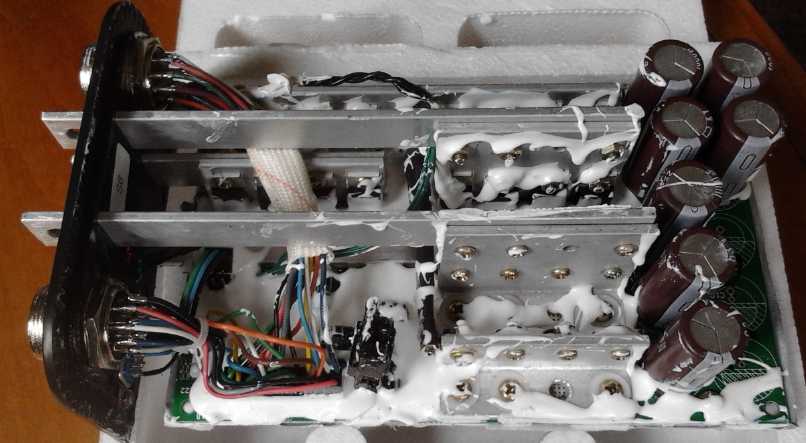
Note how the heatsink rails from the transistors extend out the end to
become the power wire connections.
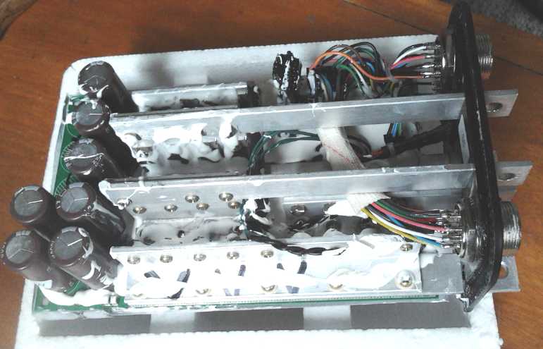
View from the other side.
A unipolar controller would cut the number of power transistors in half
from 24 to 12.
"Green" Electric Equipment Projects
CNC Gardening Machine: Tools for
the carriage
Last spring I dug up a couple of short rows of my front
lawn and planted wheat, and a row of barley. Both grains grew nicely
and
yielded seed. Next year I'd like to be more ambitious and do a wholely
larger area to get useful amounts. But it would take a lot of manual
work to dig up a whole good section of lawn with a shovel and prepare
it to plant. Yet it would be too small an area to bother bringing in a
tractor, even if one were available. It might be feasible with a
rototiller, but I think it would probably be most practical with the
CNC gardening machine.
As I occasionally think about the CNC gardening machine
idea, I try to imagine what sort of tools will attach to the tool
carriage. The most important thing is a cultivator - the really
backbreaking job is tilling the soil in the spring before planting,
especially on unprepared ground, eg, ground that has been a lawn. I've
thought of trying to adapt rototiller parts, small plows, and post hole
augers to perform this function, or even to have it simply drag a steel
rod through the ground.
At the start of the month I discovered my brother had a
small
electric rototiller. I had never seen such a thing, only fairly large
gasoline powered ones. Where from?... Home Depot. I went out there on
the 4th and found they had the rototillers ("Ryobi" brand, 240$), but
also electric or gas "Extend-It line" power heads that fit a number of
tools including
the same rototiller mechanism with a pipe extension, for 110$. This
seemed like the very thing needed and I bought one. The tines were just
7" in diameter (and stamped out of fairly thin steel plate), but with
the pipe
head and by removing the guard (since no one would be near it while it
worked) it could be dug in right under the ground to go deeper. It had
4 sets of tines, but if it proved too hard to turn the soil, or if it
pulled or lifted the whole CNC carriage assembly against its will, 2 or
even 3 of them could be removed. Since the computer will do the work,
we don't care much how long it takes to do it. Another thought is that
if a computer is controlling the motor, the tines might be made to
churn back and forth instead of simply spinning. A third thought is
that if it was too hard to turn, tines of even smaller
diameter could be made, eg, 4", 5" or even 3" -- whatever would work
easily,
along with the machine digging it right into the ground to cultivate at
any desired depth.
Next, the loosened dirt will be full of weed or grass bits
or
clods. Something like a coarse pair of curved 'pitchforks' that come
together like a jaw with saber teeth can pick them up - pick up
whatever they may latch onto - then they can spin or shake to release
dirt, then carry whatever they're still holding over to one corner and
dump it.
For a simpler tool, the machine could just rake the dirt
back and forth, pulling whatever came with it over to the sides.
Or, something I saw once that seemed quite effective, was
a big drum screen that turned slowly. The dirt (hand shovelled into it)
fell through as it turned, while rocks and plant parts gradually moved
along the length and fell out the back end. Perhaps one of these could
be worked into the picture, but with the gardening machine picking up
and dumping in the weed clods, and then returning clean soil.
The closest Home Depot had no electric power heads. The
next day (5th) I decided that since it needed power of
some sort, I would go to the Home Depot store in Duncan, where there
were said to be three of the electric power heads in stock, and get the
one made for it. It also occurred to me that if I didn't get around to
doing the gardening machine by next spring, this 45$ part would at
least allow me to use the tiller by hand.
That 125 Km round trip winding over Malahat mountain and
through the hills, with road construction delays, finding the store,
getting lunch et al, pretty much shot the work day. I was amazed to
find that this small town seemed to have more and bigger box stores
than Victoria, and Home Depot was in just one of two or three giant box
store clusters, this one well beyond the town itself, with many more
stores along or near the main road/highway in between.
On about the 24th I decided that a 'weedeater' attachment
might also be very useful, for mowing a lawn or reaping grain, or
turned vertical to cut an edge or to whack weeds between plant rows,
right at the ground. I went back to the closer Langford store. They had
just one unit of one of the two 'weedeater' models. It cost more than I
hoped, 90$, but I bought it.
Aquaponics
& LED Grow Lighting Project
It seemed to take all summer to get the greenhouse for the
aquaponics done, and now it's fall. I have no workable plan for making
the greenhouse heatable for the winter. I got the apartment size fridge
for an insulated tilapia fish tank earlier, and now I have obtained a
larger, but still not "full size" fridge I saw on a boulevard - if it
can be made waterproof.
With that in mind, I thought it might be best to
use the small one indoors for baby fish and the large one in the
greenhouse - but only in summer months. I would set up an indoor
aquaponics system in the battery lab, which has a south wall with
windows. (LED lighting is great but some actual daylight would be
helpful if not essential.) Facing facts, that's probably the only real
chance of getting a system working any time soon, and indoors would
probably be the best place to have it in arctic dwellings too, so that
nothing external would have to be heated.
The fridge/fish tank would be on the floor under the
windows, and the plants above on two levels, on a table and an upper
tier with the LED lights not very far above them.
Later I was reminded
that in the arctic
the sun doesn't stay toward the south: it goes around in circles, from
south at noon to north at "midnight". Maybe some tracking mirrors? And
it may not be seen much or at all in winter.
On the 16th it occurred to me the small fridge could be an
insulated flooded plant tank, which would prevent loss of heat there as
the water went through the system. For this winter I'll stick with the
indoor plan. On the 20th, having decided I didn't like any table I had,
I made one for the drain-down plant growing tub.
Electricity Storage
Turquoise Battery Project
On the 2nd I e-mailed Barite World to see what had
happened to my order of conductive carbon black ordered in early
August. (He had said he'd be on holidays until the 24th.) The response
was something like "Yes I got the money. I'll get around to it this
week." (Arg! Hey, it's all waiting on this, eh!)
It finally arrived on the 15th, in box containing a sealed
black pail of about 6 litres. I expected to open the pail and find a
small plastic bag with the one pound of product in the bottom, but
there was no bag. The amazingly lightweight conductive carbon black
filled this big pail to a little over 1/2 full.
Furthermore, dipping the leeds of the ohmmeter into the
bucket of loose, flowing (and drifting into the air) powder gave a
reading of 48 ohms. Pressing them against the side of the pail to
compact the powder brought readings down to the ones of ohms level.
Graphite powder in a jar gives the tens of ohms readings,
or sometimes over 100, but it's much denser. I'm sure this conductive
carbon black is the best stuff!
No loose active chemical powder has given me any ohmmeter
reading. Only if it's well pressed together is there any real sort of
conductivity.
Much as I wanted to get the project going again, the
Electric Weel motor had priority and I
didn't get anything done.
http://www.TurquoiseEnergy.com
Victoria BC