Turquoise
Energy Ltd. News #81
October 2014 (posted November 3rd)
Victoria BC
by Craig Carmichael
www.TurquoiseEnergy.com
= www.ElectricCaik.com
= www.ElectricHubcap.com
= www.ElectricWeel.com
Features: Aquaponics! (see October
in Brief, Other Projects)
Month In Brief
(Project Summaries)
- Aquaponics - Solar Panels, CAT wall socket & LED "clear
cracked ice" diffuser - Variable Transmission - Unipolar Motor -
Coursera: free university education! - Wind Wave and Tides course.
In Passing
(Miscellaneous topics, editorial comments & opinionated rants)
- Another "History of Money" video - Let's BE the Government -
Population
Control - Spiritual Teachers and Students
Electric Transport - Electric
Hubcap Motor Systems
* Variable Torque Converter Transmission
* Unipolar Motor & Controller
Other "Green"
Electric Equipment Projects
* Aquaponics & LED Grow Lighting Project
Electricity Storage - Turquoise Battery
Project (NiMn, NiNi), etc.
* Reason for self-discharge: Oxygen entering cells?
* Next Cell - not very good (so far)
No Project Reports on:
Electric Weel Motor-generator, Lambda
Ray Collector, Magnet motor,
Woodstove/Thermal Electricity Generator,
evacuated tube heat radiators, CNC gardening/farming machine.
Newsletters Index/Highlights: http://www.TurquoiseEnergy.com/news/index.html
Construction Manuals and information:
- Electric Hubcap Family Motors - Turquoise Motor Controllers
- Preliminary Ni-Mn, Ni-Ni Battery Making book
Products Catalog:
- Electric Hubcap 7.2 KW BLDC Pancake Motor Kit
- Electric
Caik 4.8 KW BLDC Pancake Motor Kit
- NiMH Handy Battery Sticks, 12v battery trays & Dry
Cells (cheapest NiMH
prices in Victoria BC)
- LED Light Fixtures
(Will accept BITCOIN digital currency)
...all at: http://www.TurquoiseEnergy.com/
(orders: e-mail craig@saers.com)
October in Brief
Aquaponics
 Sometime near
the start of the month when I was spray
painting the Weel generator, I thought to also paint the inside of the
iron circpump for the aquaponics with polyurethane spray. That seemed
to completely stop the plenteous rust it had been emitting - a night
and day difference. On the 4th I set up the aquaponics tank and filled
it,
then spent more time draining it and fixing leaks.
Sometime near
the start of the month when I was spray
painting the Weel generator, I thought to also paint the inside of the
iron circpump for the aquaponics with polyurethane spray. That seemed
to completely stop the plenteous rust it had been emitting - a night
and day difference. On the 4th I set up the aquaponics tank and filled
it,
then spent more time draining it and fixing leaks.
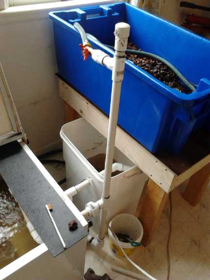
Studying some aquaponics videos reminded me that one needs
a sump basin to take up the sudden outpouring of water from the
drain-down bin. It has to be the lowest point of the system, and the
pump pumps water to the rest of the system from it. The
fish tank has to drain into it from its surface level.
On the 10th I drained the tank and installed another
bulkhead pipe connector at the surface level for this. I purchased a
"13 gallon" rectangular plastic 'bucket' for the sump. It was just the
right height - the same height as the fish tank. Later I realized all I
had to do was run the pipe from the one at the bottom upward to surface
level outside the tank, and also that all lower bulkheads could be
"shut off" if
necessary without a valve, simply by screwing a plug into the threaded
inside end. Water exiting from the bottom is better because it should
suck out fish poop, so I changed it. (It does, but only with extra flow
- a 'cleanout cycle'.)
Over Thanksgiving weekend between my brothers Ian (a
one-time salmon farmer with a degree in aquaculture) and Stuart (a
biochemist, visiting from Toronto) and me, we determined that brook
trout might be an excellent choice of fish for my locale. They're
actually a species of char, and evidently tolerant of warmer water than
other trout. I had previously rejected trout, thinking they'd need
water too cold for good plant growth. But there's videos of people
doing
aquaponics with rainbow trout, so I was probably wrong. OTOH, the trout
videos didn't give much info and they didn't seem to show off their
vegetables that I recall. But it seems likely there are brook trout in
a lake near here.
I decided to stick with the tilapia indoors with LED
lighting plan for this winter, and see if I can find some brook trout
minnows in the spring. If so I'll make an aquaponics setup probably
with an outdoor "trough" pond in a shady place, and flow the water
through plant beds either outdoors or in the greenhouse. The summer
tilapia setup would be entirely in the greenhouse. Having two
aquaponics systems I'll be able to see which works better after a year
or two, or if it's worth maintaining both. or neither.
 On the 13th I
'mounted' a 200W aquarium heater in the
fridge/tank and heated up the water from 20°c to tilapia
temperature, about 25. I didn't get the half dozen fish until the 19th,
after doing more of the plumbing. Contrary to advertising, they were
from a tank of 16° water full of algae, and already 6 to 8" long...
but they were the smallest fish available from two aquaponic peoples'
selections.
Many of the rest
looked like very good meals already. The next evening, considering that
I had no plants growing yet, I went to my brother's and got some
duckweed from his pond. He warned me that it was very hard to get rid
of. His pond water was also teeming with some tiny 'bugs' that on close
inspection looked
like very tiny freshwater shrimp. I put them in the tank but all was
gone in a few hours. I added some more, and this time saw the fish
gobbling up the duckweed - and no doubt they were eating the shrimp. No
wonder they didn't seem very interested in the fish food! The only
place I could try to keep the remaining duckweed was at one end of the
drain-down tank, which I didn't fill completely with lava rock. The
shrimp,
however, gradually disappeared. I think maybe the water was too warm
for them - or else the duckweed wasn't what they ate and they had no
food.
On the 13th I
'mounted' a 200W aquarium heater in the
fridge/tank and heated up the water from 20°c to tilapia
temperature, about 25. I didn't get the half dozen fish until the 19th,
after doing more of the plumbing. Contrary to advertising, they were
from a tank of 16° water full of algae, and already 6 to 8" long...
but they were the smallest fish available from two aquaponic peoples'
selections.
Many of the rest
looked like very good meals already. The next evening, considering that
I had no plants growing yet, I went to my brother's and got some
duckweed from his pond. He warned me that it was very hard to get rid
of. His pond water was also teeming with some tiny 'bugs' that on close
inspection looked
like very tiny freshwater shrimp. I put them in the tank but all was
gone in a few hours. I added some more, and this time saw the fish
gobbling up the duckweed - and no doubt they were eating the shrimp. No
wonder they didn't seem very interested in the fish food! The only
place I could try to keep the remaining duckweed was at one end of the
drain-down tank, which I didn't fill completely with lava rock. The
shrimp,
however, gradually disappeared. I think maybe the water was too warm
for them - or else the duckweed wasn't what they ate and they had no
food.
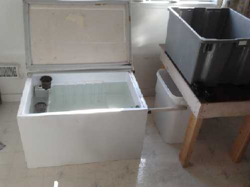
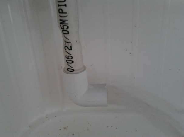
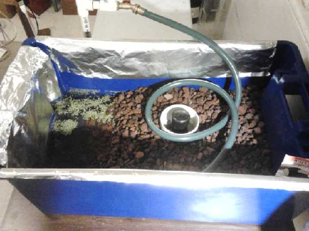 The drain-down bed with some duckweed at one
end and red lava rock grow media.
The drain-down bed with some duckweed at one
end and red lava rock grow media.
The top of the bell syphon is seen as is the hose from the water circ
pump,
and aluminum foil to help reflect whatever sun is to be had.
With sprouts now coming up, this bed definitely needs some LED grow
lights.
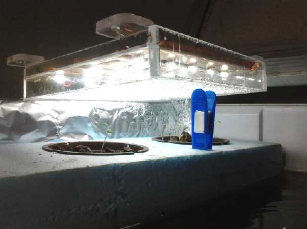 Later I planted some lettuce in
the flooded bed directly in the "freezer compartment" of the fridge
fishtank. There was so little light it started growing tall and
spindly. I finally got an LED light over it, which was no more than
adequate from a few inches away.
Later I planted some lettuce in
the flooded bed directly in the "freezer compartment" of the fridge
fishtank. There was so little light it started growing tall and
spindly. I finally got an LED light over it, which was no more than
adequate from a few inches away.
The disadvantages of growing the plants directly over the
fish tank started to show: First, the fish could get in and will
doubtless eat the roots as the plants grow. Second, I won't be able to
close the lid at night when they get taller. Third, I can't have the
light on and close the lid. Finally, they're not in the daylight from
the window. I'll probably make a separate floating plant bed, on a
shelf at the windowsill or even higher up in the window, and move them.
And I think I'll attach a couple of foot square mirrors on
swivel mountings to the window frame, that can aim whatever daylight
there is onto the plants - and from above. But as for
light, the 1 watt per square foot range of insolation implied by the
solar panels' performance
in the usual heavy overcast might be fine for vegetation on Ganymede or
Titan, but Earth summer garden vegetables will turn yellow and die.
(Full
sunlight square on is about 100 watts/sq.ft.)
Solar PV
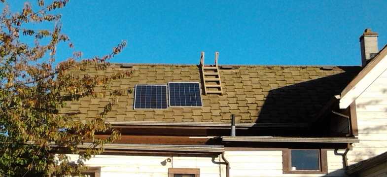 On the 7th I
installed one of the two solar PV panels on
the 45° slope west facing house roof to extend the solar power into
the evening. To catch maximum sun all day, my ideal would be an arc of
panels tilted north-south by the angle of the latitude, ie flat at the
equator, 35° (facing towards the sun) at 35°, etc. In the
east-west direction, the east end panel might be also tilted, eg, for 5
panels: 60° towards the east, the next one 30°, then level,
then 30° and 60° west. Practicalities supervene. I have the
south and west slopes covered. One panel on the east slope could help
cover early morning, but it'd be a bigger project to get one up there
safely.
On the 7th I
installed one of the two solar PV panels on
the 45° slope west facing house roof to extend the solar power into
the evening. To catch maximum sun all day, my ideal would be an arc of
panels tilted north-south by the angle of the latitude, ie flat at the
equator, 35° (facing towards the sun) at 35°, etc. In the
east-west direction, the east end panel might be also tilted, eg, for 5
panels: 60° towards the east, the next one 30°, then level,
then 30° and 60° west. Practicalities supervene. I have the
south and west slopes covered. One panel on the east slope could help
cover early morning, but it'd be a bigger project to get one up there
safely.
I intended to put up the other panel, but I couldn't find
the angle bracket pieces I'd cut to mount it. I kept thinking they'd
turn up somewhere, but finally on the 30th I cut another set of four,
drilled the holes, and screwed them onto the collectors. On the 31st
there was a sunny break and I put it up on the roof. Seeing where the
shadows were trending, I mounted it a little higher than the first one.
(Some cherry tree branches are going to get clipped.)
I had disconnected the panel from the lower roof and I
wasn't going up in the ucky attic (full of fiberglass dust etc) twice,
so I
hadn't connected the first panel and neither of them was doing anything
useful. In the typical west coast overcast weather the four south
facing panels weren't doing much either, and the auxiliary battery
charger was often taking much of the load of the peltier fridge and the
new
LED 'flat box' grow light for much of each day. The two new west facing
250 watt panels will rendered some assistance in the afternoons now
that they're hooked up as of November 1st & 2nd. (I
had to go up twice after all.)
Then there were a couple of little 12 VDC power projects,
both done in a day:
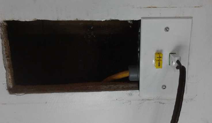 CAT Standard 12 VDC wall outlet in standard
electrical box,
CAT Standard 12 VDC wall outlet in standard
electrical box,
powered from solar PV system and installed for use with the aquaponics
setup.
(Later the remainder of the pre-existing hole in the wall was covered.)
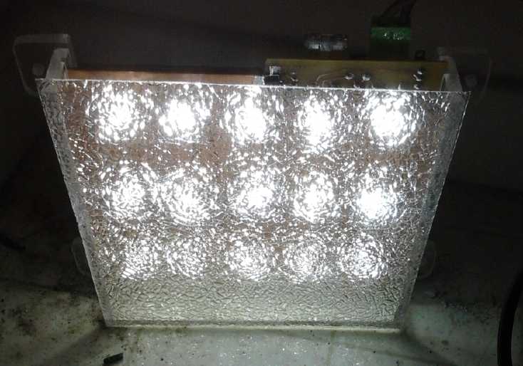 LED light" Previous diffuser was replaced with
"Clear Cracked Ice" diffuser plastic for use as plant grow light.
LED light" Previous diffuser was replaced with
"Clear Cracked Ice" diffuser plastic for use as plant grow light.
(I think this type of diffuser might be good for space lighting if the
light is mounted on a fairly high ceiling.
It breaks up the worst of the intense point source LED light, but less
effectively than the translucent version.)
I'll be making more of these with the 450nm blue and 660nm red LED
emitters especially suited for plant growth.
I'll mention in passing that I put together another cell,
with the more conductive carbon black, on the 23rd. It hasn't performed
well, probably largely because the posode was too thin to be held
properly compressed in its space. I wasn't able to put much time into
it. I'll have to get back to it next month.
Variable Torque Converter Transmission
 I eked out a
little time to work on this, and made the
mid-shaft section that couples the variable planetary gear output (ring
gear, with a spline socket center) to the input rotor of the large
centrifugal clutch. I first got one half made from regular 1" shaft,
then I realized that, the new shaft being short, I could use the
original splined shaft that came with the gear set. I had to cut it in
two places, turn the non-spline end to 7/8" O.D. and make the bushing
hole again, but
the result was pretty much ideal - much superior to milling one end of
a round shaft to a
pentagon shape to roughly "fit" the spline socket.
I eked out a
little time to work on this, and made the
mid-shaft section that couples the variable planetary gear output (ring
gear, with a spline socket center) to the input rotor of the large
centrifugal clutch. I first got one half made from regular 1" shaft,
then I realized that, the new shaft being short, I could use the
original splined shaft that came with the gear set. I had to cut it in
two places, turn the non-spline end to 7/8" O.D. and make the bushing
hole again, but
the result was pretty much ideal - much superior to milling one end of
a round shaft to a
pentagon shape to roughly "fit" the spline socket.
After I got that cut to length, I set the motor on its 3
inch "stand-offs", marked out the holes, drilled, and then threaded
them. Shaft alignment seems pretty good - cetainly better than with my
previous configurations.
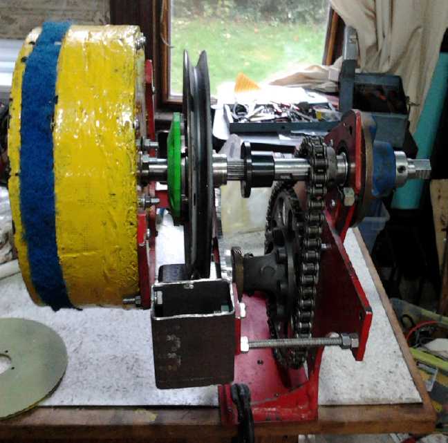
The view shows the assembly without the centrifugal clutch
disk & drum, which mount on the black bushing and on the shaft next
to
the chain, respectively. The large pulley is the slipping gear of the
torque converter, to have the tensioning rope from the 'gear shift'
lever wrapped around it.
Unipolar Motor
 With the
promise of at least a better motor and controller, and even better, the
probability of it doing more with less energy, I set to work on the
unipolar Electric Caik motor and the controller, to be tested as an
outboard motor. Changes to the 'regular' bipolar BLDC motor are a
unipolar magnet rotor and an optical interrupter rotor position sensor
system. The more common hall effect magnet sensor system would be tough
to position and adjust properly without clear and obvious north-south
magnetic field transition points. I made the rotor and created a small
interrupter drum (slots
yet to be cut) for the optical system from a suitable PVC plumbing pipe
fitting.
With the
promise of at least a better motor and controller, and even better, the
probability of it doing more with less energy, I set to work on the
unipolar Electric Caik motor and the controller, to be tested as an
outboard motor. Changes to the 'regular' bipolar BLDC motor are a
unipolar magnet rotor and an optical interrupter rotor position sensor
system. The more common hall effect magnet sensor system would be tough
to position and adjust properly without clear and obvious north-south
magnetic field transition points. I made the rotor and created a small
interrupter drum (slots
yet to be cut) for the optical system from a suitable PVC plumbing pipe
fitting.
I balanced the rotor as best I could anticipating that I
would run it at higher RPM's than previous rotors - and attain higher
boat speeds.
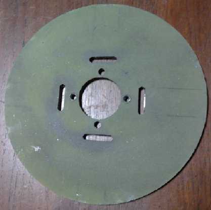
Above: Unipolar Magnet Rotor - four magnets...
with
the new thru-slot radial epoxied strapping wrapping
that should be safe for higher RPM.s (3000 instead of 2000?)... and
four large spaces between.
 Drum fitting (to be slotted) on shaft for
optical rotor/magnet
position sensor system.
Drum fitting (to be slotted) on shaft for
optical rotor/magnet
position sensor system.
I also did considerable design work in the last week on an
MC33035 based unipolar BLDC motor controller and the PC board for it.
The motor won't run without the controller! Of course some creative
design (and a CMOS 4000B logic NOR gate chip) was needed to allow CRM
instead of or in addition to PWM, but at newsletter time the schematic
is mostly complete and the board layout is largely figured out, but
much trace routing and some layout logistics remain.
Coursera.org and "Wind Wave and Tide" renewable energy course
 I started
taking a course from University of Toronto via www.coursera.org , "Wind, Wave
and Tide", about generating electricity from those sources.
Coursera.org allows anyone to take courses or even get a university
education free, on-line, from their home computer. It features many
world renowned lecturers.
I started
taking a course from University of Toronto via www.coursera.org , "Wind, Wave
and Tide", about generating electricity from those sources.
Coursera.org allows anyone to take courses or even get a university
education free, on-line, from their home computer. It features many
world renowned lecturers.
While I have
my "Diploma of Electronics Engineering Technology" and a number of
sundry courses [far] behind me, this is the first course I've ever
taken from a university. And actually, I'm only doing the lectures and
'practice questions', not sitting for exams and labs to get the
certificate. But I now largely understand what drives the world's
winds! It seems that Savonius VAWT rotors that I've been
considering making don't make particularly efficient use of the wind -
only about 60% of a propeller type. But that's not bad, and they're
better at low wind speeds and in gusty or variable winds that keep
changing direction.
I
came up with the idea to make a darieus-segment sort of VAWT with
auto-pivoting blades, that would self-start. Then I found on youtube
that Alex Erauw (Belgium) already has a savonius-darieus hybrid VAWT
that turns 3 times
faster than other savoniuses, or in other words almost 3 times the wind
speed. Perhaps it extracts more of the available wind energy, and it
appears to have fixed blades - simpler than my idea. If so it achieves
what
I was after. But the video didn't show the airfoil details clearly, and
he says they're pretty critical. Then another video also from Erauw
shows a fixed position 'wind funnel' structure with four openings (Open
to "the four winds"?), that he claims doubles the wind speed going into
the turbine. Wind power is proportional to the cube of the wind speed,
so this would be extremely valuable in low average wind areas. It would
appear Erauw is at the forefront of vertical axis windplant design -
when I see an interesting design on youtube it usually turns out he
made it.
But another design from Germany shows a wind shield aimed
by a vane, shading the 'lee' (counterproductive) side of the rotor -
just such as I proposed some months ago. The wind shield could probably
be combined with the wind funnel as a pivoting funnel-shield. On the
other hand... whatever the design it has to stand up to whatever wind
comes at it when there's a gale, and the simpler designs with the
shortest shafts are most likely to stand up without making overly heavy
constructions. And a larger but simple turbine, even if it doesn't make
optimal use of the wind, will provide as much power as the optimized
but smaller one and maybe for less cost. It's like the ideas to have
solar panels track the sun: it's now cheaper just to buy extra panels,
and fixed mountings are more robust, safe and trouble free.
Of course I'll have to leave VAWT construction to some
later date when I have more time. And I should look at
this week's segment of the course, which evidently covers practical
siting and design costs.
----
I had intended to get the body hole drilling templates
done on the Electric Weel motor/generator, but didn't. In November I'll
also be doing a revised one for the Electric Caik (unipolar edition),
so maybe I'll do them both then, since they both need similar
spreadsheets, G-code setup and CNC drill-router work.
In Passing
(Miscellaneous topics, editorial comments & opinionated rants)
I looked at a number of movies on youtube about the state
of affairs on the planet. One I thought was especially interesting was The
Impending
Collapse
of
the
Global
Economy. It was more an in depth
history of money of the USA from the times leading up to the American
revolution on. It seems there were a lot more well organized, well
funded manipulations and political murders by greedy banksters over the
decades than one
would ever suspect.
As the movie repeatedly pointed out, it seems clear that
an agency of government, hence responsible to the people, should be the
issuers of a nation's money supply and that nations shouldn't incur
debts. Banks should never be allowed to lend out more money than they
have on deposit.
The quantity of the money supply, and its original issue
as credit rather than as debt, is the critical point, and if issued by
greedy private interests, they create easy credit, then dry it up to
create depression and crises and buy up peoples' assets at low cost.
However, when governments try to start printing money
presidents get shot, credit from banks suddenly dries up on orders
'from the top', and normal mortgage and loan renewals are denied, to
rapidly create mass foreclosures, business failures and deep
depressions in the economy - which the public is then led to attribute
to the printing of money by the government instead of by a private
central bank.
If people don't understand what's happening and support to
the hilt proper ways of doing things, if politicians are easily swayed
or too timid to act, will the parasitic plague of banksters continue
killing presidents, bribing elected and civil service officials,
stealing peoples' farms, houses and pension funds, and swindling
everyone double through inflation and sudden money supply or credit
contractions?
Electoral system changes and referendum calling ability by the populace
are some of the answers.
One sees time and again the public winning
some big fight, and the vested interest party coming back after it
seems to be all over, on some modified tack, and having worn the public
out, they eventually get their way. Here in Victoria a manipulative
lawyer wanted to make a "mega-yacht" terminal in Victoria Harbor, a
harbor that is really too small for current needs. Organized public
outcry stopped the project. Now, two years later, the instigator has
moved the project a couple of hundred yards down the shore and rapidly
started building it without anyone knowing it was coming. No doubt he
quietly got some sort of permit from someone without any publicity or
hearings, perhaps by misrepresentation, to sneak it by to be presented
as a fait accompli. The pile drivers can be heard working furiously.
The banksters fought several times to gain control
of the US money supply, from the days it was a colony onward, finally
losing it only to come back and try again a few years later. The
repeatedly bashed population and string of murdered presidents gave up
in 1913 and the "Federal Reserve" (privately owned bank - not federal
and with no reserves) has more or
less ruled the USA ever
since.
If any such projects affecting the public might have to
pass a referendum called whenever and wherever enough people demanded
it, before it was started or yet still after it was in operation, the
proponents would at least have to try to make a good case publicly, and
bad plans such as private control of the money supply would be stopped
dead in their tracks every time they raised their ugly heads, until the
greedy give up and accept their equality with others.
Then again, we could also change the whole money thing.
It's said that on some planets, there is no money. Instead what is
controlled is what people are allowed to own. The 'richest' are
permitted up to four times as many possessions as the 'poorest'. Excess
can be confiscated. This works because really everyone has plenty, and
the population is controlled to prevent development of scarcity. There
are "trusts" rather than private corporations. No way would these
societies put up with a few people controlling most of the wealth. Of
course, such developments may be premature here... or not. I'm not sure
how this would work on Earth in regards to, say, art collections or
manufacturing and farm land or collective properties, but it sounds
like a great idea worth exploring.
Listening to videos and drawing conclusions, unfortunately
usually negative, about how things are being run and how they're
working out, is one thing. But figuring out anything productive to do
about them is another matter. But at some point recently I had a
brainstorm: start an e-mail discussion group to talk about anything of
interest in my muicipality, Esquimalt BC Canada. On the 15th I started
the group "Esquimalt Online", Esquimalt@yahoogroups.com , and, an
election being on with candidate posters up everywhere, I made a poster
for the front boulevard: "Esquimalt Online" - Join the Discussion - and
instructions for joining. That didn't seem to get anyone joining and I
decided it needed more explanation. As I wrote on the 17th:
Our institutions of governance,
set up in simpler times and without provision for change and progress,
are today archaic. We have the internet for rapid communication, a more
educated population, and many conflicting ideas - some pushed by
special interest groups - of what it might be good for a municipality
or other government to do or not do. Yet we have almost no input and
increasingly we are being controlled by out of touch governments
instead of controlling them for our own collective benefit. We have the
right and increasingly the need to participate in decision making
processes, and to not have all governing power be concentrated into few
hands with little public input.
We need a vehicle whereby the peoples' representatives can be informed
by the people collectively what we want them to do, or to not do; what
bylaws, regulations, policies, and public works we want or do not want.
At a "meet the candidates" meeting, I gave out 1/2 page
pamphlets, on the above lines. A number of people said "Great idea!",
but still no one signed up. I think the idea and implications of
actually being able to run a government instead of being run by it is
too different for people to immediately grasp. I shall persevere. Next
sign was to be something along the lines of:
=============================================
Let's
BE THE GOVERNMENT
of Esquimalt!
In 1.s we are ignored.
In 10.s we have a voice.
In 100.s, if we have a consensus,
what we say we want, will be done.
Join Esquimalt Online today!
e-mail to:
esquimalt-subscribe@yahoogroups.com
=============================================
I thought this e-mail discussion group format had the
potential to be "version 1.0" of the governing vehicle.
But someone told me there are already discussions going on
on facebook. Not being a social media fan so far, I haven't done
facebook. I signed in once and now get daily spam from them. But I'll
join if facebook is at last unmuzzling Esquimalt's
"silent
majority". If it's working, great! If it doesn't seem to be what's
needed, I should at least be able to advertise the e-mail group there.
I sometimes wonder why no
one of authority has taken up the conversation about global
overpopulation since it was realized the "population explosion" was
approaching, in the 1960.s
and 1970.s. Then I think: if people were admonished to have fewer
children, the more socially responsible and intelligent would probably
realize that was right, and would have fewer children, while the
irresponsible and unthinking would carry right on having large families.
Thus, the most desirable genetic stocks would selectively
be reduced
and eliminated from the population while the least desirable would
proliferate. This would be a disaster for civilization. And this in
fact does appear to be happening. At least, the 'developed' nations
have
birth rates well below replacement levels, while other groups in
already overcrowded "third world" lands continue to proliferate, and
the
overflow is continuing the undesirable population expansion and
flooding into the 'developed' lands, changing the
character of their populations. The ancient Greeks seemed to be a more
capable people than the modern ones. What will the species as a whole
be like in a few thousand years if this should continue?
Yet, enforcing size limits on all families would gain
little
traction in today's world*. How then can responsible people even
attempt to address the question?
Under these conditions, the population growth continues,
putting increasing pressure on the world's land and resources until
pandemics and a
collapse are now inevitable. Ebola seems to be new, but hemorrhagic
fevers were probably part of the "black plagues" of some centuries ago,
and we still don't have 'antibiotics' for viruses.
Even after such a collapse, putting limits
on family sizes will be a hard sell -- but such a hard experience as
the
world will have passed through will make the vital need for limiting
population
understood much more clearly than it is today, and I trust people will
then bite the bullet and enforce such a measure to prevent a similar
future calamity. At the same time, hopefully the obvious desirability
of having
more people who are more capable and spiritual will be worked into the
equation.
* China's one child policy is an
important exception, the one
such plan in effect. Problems notwithstanding, it has doubtless had a
big impact in reducing family sizes and slowing
China's population growth. China had 1/4 of the world's population in
the 1960.s, and today (notwithstanding China's rise from "3rd world" to
economic stardom, and further population growth) it's closer to 1/6th.
I usually take pieces of what I find and put it into my
own words. I don't think I could do this quote justice:
"A true
spiritual teacher knows that there really aren’t teachers and students.
All are involved in the same learning process, sharing the lessons and
the understandings, to together achieve the goal of perfection. Every
soul you meet on your path is your teacher and your student because the
goal of the ages – perfection and the likeness of the Father – is a
goal that can only be achieved in collaboration, since all are part of
God and all are one. The actions of one human being may be outstanding.
The actions of humanity working in harmony under the guidance of God
can achieve the impossible, even turning a backward material world into
a kingdom of true perfection and beauty." www.1111angels.net
Daily
Log
(time accounting, partly for CRA - SR & ED purposes)
1st to 4th: Worked on TE News #80. Spray painted Weel
generator & inside of the iron circpump for the aquaponics with
polyurethane spray. Then I set up the aquaponics tank and filled it.
5th: The compression fitting leaked so I replaced it with a bulkhead
pipe
connector.
6th: That leaked a little so on the 6th I drained the
tank with the pump and tightened the nut a little more. That seemed to
cure it.
7th: I installed one of the two solar PV panels on
the 45° slope west facing house roof to extend the solar power into
the evening.
8th or 9th: except studied some
aquaponics videos.
10th: I drained the tank and installed another
bulkhead connector, this one at the surface level. Purchased a "13
gallon" (US or Canadian gallons?) rectangular plastic
'bucket' for the sump. It was just the
right height - the same height as the fish tank - except that it was
1/8" too tall to fit under the table where I wanted to put it. I
unscrewed and broke the glue on two side supports of the table and
ripped 1/4" off them, then screwed them back on. The bucket now fits
under those two sides: It can be pulled out the front or the table can
be pulled away to the right. I then went to look at aquaponics
plumbing diagrams.
(Thanksgiving weekend: discussion about aquapoincs)
13th: I 'mounted' a 200W aquarium heater in the
fridge/tank.
14th: I tidied up some construction/finishing
details around the greenhouse door, then spent the afternoon shopping
for supplies, including a centering drill bit for the lathe. In the
evening I drilled a centered end hole for the bushing in the 'in
between' shaft for the variable torque converter transmission, which
I'd cut to length and faced square the previous day.
15th: made splined shaft for the variable
torque converter transmission (see report). I didn't get the keyway
done for the rotor's "H" taper lock bushing, and I left the hole
slightly undersize. The next morning (16th) I attempted to mill the
keyway, but found the end mill to be dull. I bought a new one and while
I was there I looked for a boring bar to ream the hole to precise size,
but the store didn't have one. On the way home I picked up a couple
more pipe fittings for the aquaponics. I phoned another store. It had
boring bars, in sets, and I bought one.
The new end mill didn't work any better than the first
one, immediately starting to get dull. The shaft steel was too hard for
them!
16th: I put together some of the pipes in the aquaponics system.
I came up with the idea to aerate the tank using a pipe with the end
closed off and some tiny holes drilled in it for the water to spray out
of, instead of the garden hose sprayer. I made this and it seemed to
work well, but the top pipe hole in the tank was a little low down, so
some fittings - or a bend in the pipe - would have to be used to raise
the holey pipe up above the water level. Surprisingly, the #56 drilled
holes seemed a bit on the large size. I had thought they'd probably be
too small.
17th: I visited AGO and asked the machinist about
the key slot milling. He said I needed a carbide toothed end mill. I
hadn't looked for those at the store the previous day since I didn't
know there was such a thing. I wasn't sure I could get one, so he
loaned me one. I was also given some coolant to keep squirting on the
tool as it slowly cut, at "under 900 RPM". Then people kept visiting me
all afternoon, one after the other, and I had to go out in the evening,
so I
still didn't get at milling the slot or the hole.
Also 15th to 18th: I worked on starting a new
e-mail group, "Esquimalt Online", to discuss municipal issues. Since
this isn't directly related to energy issues, I've put it in the "In
Passing" section.
18th: got the aerator spraying properly.
19th: Business breakfast; had to buy parts; finished most of the
plumbing; In the evening I went
out of town to where the tilapia were for sale and bought six.
20th: I got the shaft finished and tried fitting it onto the
transmission. It didn't quite fit and I cut 1/4" off the end. In the
evening I went to a pond and got some duckweed with tiny 'shrimp' and
tiny
snails.
21st: Fitted gear and taper-lock ("H") bushing to the center shaft, and
the Electric Hubcap motor to the transmission housing with the shaft in
place; measured up where the shift (tension) cable might go.
2nd, 23rd: Put together a Ni-Ni battery cell. Made bell syphon for
aquaponics and got it working.
24th: Fixed some broken links on the web site and re-uploaded the motor
controller making manual, which had somewhere got deleted. Finished
bell syphon housing and added some lava rock to plant bed. Battery
isn't working well or holding charge (see report).
25th: Put lava rock in aquaponics drain-down bed, made new housing for
bell syphon and adjusted, cut slots in rotor for making improved &
unipolar Electric Caik motor.
26th: Made venturi in lower pipe to improve bell syphon (successful).
Prepared Caik rotor and mounted magnets on it. Went to a 'suppressed
propulsion systems' meeting.
27th: Balanced Caik rotor. Read about a new monopolar motor being made
in Brazil. Did much e-mail about projects.
28th: Worked on Unipolar motor controller schematic & PCB layout.
Tried 5m LED RBG strip light for growing plants. It wasn't very bright.
29th: Wired 12v house circuit from solar panel. Reconstituted 2nd LED
light with new diffuser. Trace in light's PCB burned out - repaired.
Found PVC plumbing part that can work for drum style optical slots for
Unipolar Caik motor, drilled and hacked it to fit on shaft. Worked on
controller schematic and PCB.
30th: Installed mounting brackets in second solar panel.
31st: Put up 2nd west facing solar panel.
Nov. 1, 2: Wired in the solar panels.
Nov. 3: Worked on unipolar motor controller circuit design, finished
this newsletter.
Electric Hubcap Motor Systems - Electric Transport
Planetary Gear
with Clutch Torque Converter Transmission Project
Full as the days were, I really wanted to move ahead on
this and get the Sprint car going. I made some progress but didn't get
it finished before deciding the unipolar motor was probably even more
revolutionary and should be built ASAP.
 I was putting
together the case width extension with the
motor "standoffs", and I thought to line the motor up I should next
make the
mid-shaft, a 3" extension coupling the variable planetary gear output
and the large centrifugal clutch input rotor. I cut a piece of 1" to
length (3.25") and did a center hole in one end for the bronze bushing,
but I've never liked having to cut a pentagon cross section shape - the
one thing I can make that will fit (if "fit" is the word) in the
planetary's 25-segment spline socket. The previous pentagon was a
little crooked, tho done as carefully as I could with the angle
grinder. This time I had the milling machine and could ensure flat,
square faces, but I still didn't like the arrangement. It seemed too
likely to wear out and start slipping.
I was putting
together the case width extension with the
motor "standoffs", and I thought to line the motor up I should next
make the
mid-shaft, a 3" extension coupling the variable planetary gear output
and the large centrifugal clutch input rotor. I cut a piece of 1" to
length (3.25") and did a center hole in one end for the bronze bushing,
but I've never liked having to cut a pentagon cross section shape - the
one thing I can make that will fit (if "fit" is the word) in the
planetary's 25-segment spline socket. The previous pentagon was a
little crooked, tho done as carefully as I could with the angle
grinder. This time I had the milling machine and could ensure flat,
square faces, but I still didn't like the arrangement. It seemed too
likely to wear out and start slipping.
Then it occurred to me that I could use the original
splined shaft that came with the gear set. It couldn't have been used
(as the longer output shaft) in the previous configurations, but now it
was a
short mid shaft. I spent the 15th and 16th cutting, turning and milling
it to be what I needed. It wasn't an inch diameter, but the requisite
uneven sections turned down smoothly on the lathe for a 7/8" I.D. "H"
taper lock shaft bushing for the clutch rotor.
In spite of the progress, the intriguing potentials of the
unipolar motor diverted me from the transmission towards the end of the
month.
Transmission Assembly,
without centrifugal clutch rotor disk and drum.
(The disk mounts on the black taper-lock bushing on center shaft and the
drum on the output shaft beside the chain sprocket, fitting over the
input disk.
Big slip pulley for controlled slipping of planetary gear torque
converter is seen at center; yellow Electric Hubcap motor at left.)
Unipolar
('monopolar') Motor
& Controller
Revolutionary potential
The point about simpler, cheaper, inherently more
reliable motor controllers wasting half the energy (and so getting half
as warm) compared to typical bipolar BLDC motor controllers decided me
that unipolar is a better configuration - at least, well worth trying
out.
But then there's the other point: John Bedini's
'monopolar' (unipolar)
motors seemed to get more energy out than expected; seemingly even more
than went in. They amazed a good number of educated people, which tends
to suggest the unexpectedly high performance is more or less proven.
Then there's Troy Reed, who said in a 2011 youtube video
he "can drive around all day" in a converted car with his new motor,
which seemed to draw considerably less current on the road than most...
but he didn't explain what the motor was. (It's said he was
assassinated in
2012. I was unable to verify this in a brief search.) Then there's the
rumored new Japanese e-bicycles from about 2012 that get a couple of
hundred
kilometers range instead of tens of kilometers, apparently with
unipolar motors.
Such monopolar motors should certainly be good at
reclaiming
remaining coil 'flyback' energy as the coils are switched off, and
obviously unenergized coils can generate electricity as the magnet
approaches them, perhaps reclaiming other energy. Plus there's the
lower iron losses, and lower motor controller losses.
If none of this proves to make any major difference,
unipolar still looks like the way to go. If it does, the potential is
revolutionary. We might start
seeing cars having ranges of 500 kilometers on a charge,
with no more battery watt-hours than cars getting 100-150 Km or less
today.
It would make a number of things much more practical than today, such
as electric commuter trains without overhead wires, solar electric
boats, and electric ferries.
This was my thinking until on the 27th an e-mail arrived
about a new motor, that appeared to provide still more evidence that
it's all true
and works better than regular motors.
The new Keppe motor is described at
keppemotor.com/about/faq.html
. They feel their motor is so good they're calling it "new physics"
principles. It gives the following performance chart:
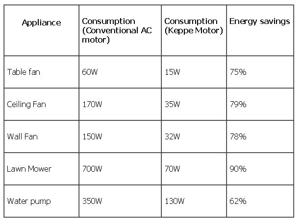
The performance
improvements appeared to be broadly in keeping with the previous
claims and rumors. Again the motor controller - and in particular,
power pulsed on and off in resonance with the coil resonant
frequencies - plays a key part.
On reading further, I discovered a major error in their
claims. They noted that while an AC motor might be efficient at rated
load, it still drew a lot of current even with no load. This is
observable with an ampmeter, and it confuses a lot of people. But the
AC current with no load is almost 90° out of phase with the AC
voltage, and simply
multiplying volts times amps doesn't give watts. The volt-amps may be
high, but the actual watts of power works out to a low figure for an
idling motor. (Multiply the volt-amps by the cosine of the phase
difference to get watts, IIRC.) So it would appear they are
overestimating the power consumed by other motors. This doesn't
necessarily negate all the savings or say their product isn't good, but
it does bring the amazing claims more into line with "normal physics"
reality.
But
I had already decided I would simply have
to do a unipolar rotor for the Caik Outboard and get the project
moving, this month, even before finishing the variable
transmission, and I had started work on it.
So far the Keppe motor is only made in small sizes -
fractions of a horsepower, and I know of no other unipolar motors in
production at present. Unless someone else jumps in before I finish, I
may have the only multi-horsepower sized units. It seems like an
excellent track to be on!
Unipolar Motor Construction
 On the 25th I
milled slots in the last remaining waterjet cut Electric
Caik rotor blank for the radial magnet strapping (or 'webbing'). (I
forgot about the "ready made" '7.8" brake rotor' from Princess Auto. I
could have equally used that.)
Since
it's to be unipolar, there'd only be 4 magnets so I did 4 slots just
over an inch wide. I had planned to drill a starting hole and make the
slots with a jigsaw, but having just milled the key slot for the
transmission, I thought of milling and of how much cleaner a job it
would do. Since I used a 3/16" end mill bit (my smallest), that's the
width of the
slots. Anyway it leaves lots of thickness for two layers of strapping.
(When I did it, the strapping only overlapped on the back side - I
didn't double it through the slot. But I used 1.5" wide strapping
instead of 1".)
On the 25th I
milled slots in the last remaining waterjet cut Electric
Caik rotor blank for the radial magnet strapping (or 'webbing'). (I
forgot about the "ready made" '7.8" brake rotor' from Princess Auto. I
could have equally used that.)
Since
it's to be unipolar, there'd only be 4 magnets so I did 4 slots just
over an inch wide. I had planned to drill a starting hole and make the
slots with a jigsaw, but having just milled the key slot for the
transmission, I thought of milling and of how much cleaner a job it
would do. Since I used a 3/16" end mill bit (my smallest), that's the
width of the
slots. Anyway it leaves lots of thickness for two layers of strapping.
(When I did it, the strapping only overlapped on the back side - I
didn't double it through the slot. But I used 1.5" wide strapping
instead of 1".)
I considered using 2" x 2" magnets, but I have just 7 of
them, and if I save them for a larger motor needing 6, that motor will
probably have more torque, whereas the problem with the Caik outboard
is getting enough RPM, not torque. And the Caik's rotor being so small
(7.5"), curved arc magnets would be a lot better if a larger size is to
be
used. Putting two magnets side by side is almost impossible because
they repel each other so strongly. So I sized them for very strong
single 1" x 2" x 3/8" magnets... which I have lots of.
The next day I scraped the paint off the rotor where the
magnets and strapping were going (see the magnet loosening problems of
the first Caik motor rotor in issues... about maybe January 2013),
sanded the rotor and the magnets so the epoxy would stick well, and
mounted the magnets with the new configuration, presumably safe for
another 1000 RPM (Caik to be rated 3000+ RPM instead of 2000+) or
better. I used
1.5" wide strapping and had only milled 1" slots, so I cut 1/4" notches
in the strapping. When things were half set and flatness on top of the
magnets was assured, I slipped aluminum brackets over the magnets to
push the strapping down over the sides of the magnets.
To balance the rotor for
the anticipated higher RPM.s
(27th), I mounted it on an axle and put the axle between two parallel,
level straightedges. In theory it would naturally roll until the
heavier side was down, and a little of the leftover epoxy (kept in the
freezer
overnight and not quite set yet) could be brushed on the
top side for weight until it showed no preference of orientation.
In practice, the shaft wasn't quite round and the rotor
would sit one way up or the opposite. I found a better shaft, which
wasn't perfect either, but by rotating the shaft inside the rotor
center and trying 2 or 3 times gave a fair consensus that one
particular side was lighter, which I marked with a felt pen. I put on
the epoxy without gaining too much. Then I stuck a couple of short
pieces of PP strap in the epoxy between magnets, one on the back and
one on the magnet side, still without getting a balance. It was better
than it was initially. Then I sanded a bit off the double-layer of
strapping on the back side of the two 'heavier side' magnets. I don't
think it's perfect, but it seems pretty close now. It may change a bit
when matched with a shaft that has key slots and a key.
The second
challenge to making the motor is the optical
sensor system for the magnet positions. A slotted disk or a slotted
drum has to mount on the motor shaft and spin with it, and three LED
and phototransistor pairs have to be positioned on opposite sides of
those slots. The drum type is superior for this application because the
shaft can be inserted from the rotor end and won't hit the optical
components, which have to be installed first, on its way past.
Having been working with plastic plumbing fittings, I
thought that there might be one that would work as a drum. I went to
Rona and found one: a PVC pipe coupling with 1.5" pipe glue-on on one
end, and .75" inside threaded at the other. The .75" threaded pipe
fitting is in fact just under 1", and I drilled it out with a 1" drill
to fit over the 1" motor shaft. The 1.5" end has a rim about the right
diameter to cut the slots into, and have the phototransistors inside
the rim
(still clear of the shaft) and the LED.s outside, on a flat circuit
board on the inside of the stator end cover. The threaded end was too
long and I cut it shorter with a hacksaw. Then I drilled in through one
side and tapped it for a long 1/4" set screw to clamp it onto the
shaft. This same fitting should work for all Caik and Hubcap motors
with 1" shafts.
The next job will be the optics circuit board. And after
all this time but having switched to hall sensors until now, I still
haven't identified proper part numbers for optical couplers to use with
interrupter slots - I've used ones from old computer mice, but I threw
the rest of the old computer stuff out a while ago since I hadn't
touched it in years and needed the space.
Unipolar Motor Controller
I hadn't worked on this since September. On the 26th I
showed the ideas to a couple of people, one of whom mentioned part of
Bedini's key was to pulse the motor on. The next day on reading
the Keppe motor material, it appears it also pulses the motor,
at a resonant frequency. I had my circuit in mind, with an in-line
coil to transiently store motor coil energy, but I hadn't considered
this resonance idea, which could attain the maximum magnetic field
with the least electrical energy. Now I began to realize that the PWM
frequency might be a key to this, so I decided to incorporate a
variable PWM frequency control in the design. (I hope the optimum will
prove to be a relatively low frequency to minimize switching losses.)
The CRM could be separate from that (PWM-on AND CMR-on =
CoilsEnable-on), to ensure maximum currents didn't exceed ratings. But
the controller is so much simpler and more fault tolerant that I expect
good results from the first design.
I got back to the circuit design and PC board layout on
the 28th and did some work on it every day after that. After trying out
a couple of layouts, I started to realize that the way the Kelly
Controller laid out the coil drive transistors was very good. It seemed
counter-intuitive that they weren't bonded to the heatsinks, but only
to aluminum bars that stuck out the ends as terminal posts, to which
the power wires were attached. But the heavy copper power wires should
themselves be good heat sinks, carrying heat away from the transistors
and even from the whole controller.
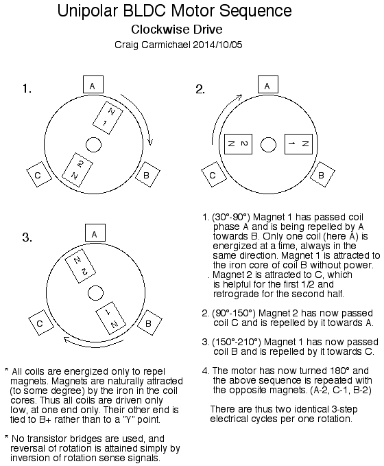
I'm not sure I explained the commutation sequence very
well last month, and a picture can be worth many words. So here's the
sequence, in a diagram.
"Green" Electric Equipment Projects
Aquaponics
& LED Grow Lighting Project
 I worked away
on
this project up until mid month, gradually getting the plumbing set up
for the tilapia and plant bed in the upstairs battery lab. I got the
aquaponics part done, but didn't get to the LED lighting.
I worked away
on
this project up until mid month, gradually getting the plumbing set up
for the tilapia and plant bed in the upstairs battery lab. I got the
aquaponics part done, but didn't get to the LED lighting.
On the 14th I also realized that I could have used the
lower opening in the fish tank after all and not made an upper one,
just by bringing the pipe up vertically outside of the tank to its
surface height, before turning it horizontal to drain into the sump
tank. In fact, that's probably a better arrangement because it'll suck
up fish poop from the bottom of the tank. Furthermore, since the
bulkhead connectors are threaded on both sides, instead of having a
valve for the (hopefully) rare occasion of shutting off the water in
the fish tank or sump tank, I can just screw in a pipe endcap on the
inside. The only disadvantage is you have to get your hand and arm wet
to do it.
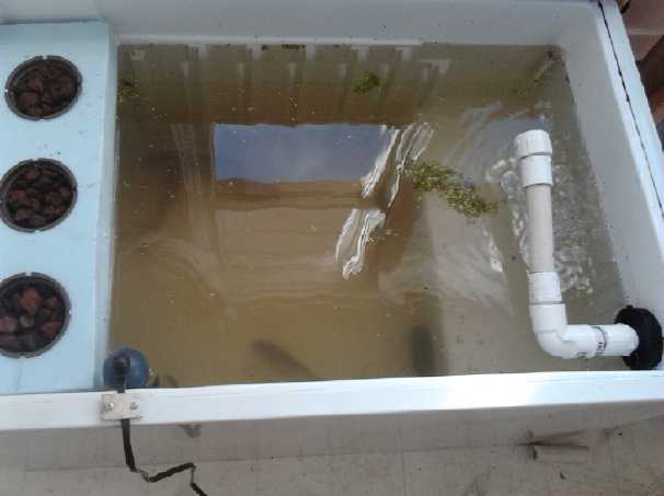
On the 16th I filled the
sump by pouring water into the tank and watching it pour out through
the overflow from the bottom. It poured more slowly than I expected,
the level in the tank rising an inch before there was a lot of flow. I
think I'd use 1" pipe instead of 3/4" next time.
I didn't want to have to add a separate air pump, and
while putting together
some piping from the pump, I came up with the idea to aerate the tank
using
a pipe with the end closed off and some tiny holes drilled in it for
the water to spray out of, instead of the garden hose sprayer. I made
this and it seemed to work well, but the top pipe bulkhead hole in the
tank was
a little low down, so some fittings - or a bend in the pipe - would
have to be used to raise the holey pipe up above the higher water
level.
Surprisingly, the #56 drilled holes seemed a bit on the large size and
the spray a bit coarse. I had thought they'd probably be too small.
(18th) I tried heating up the aerator pipe and bending it so it would
be higher up, but it wasn't enough. So after a couple more trips to
Rona for fittings that somehow still weren't in the growing pile of
them, I put in a threaded elbow that I sanded down the corners of so it
would turn past the wall of the tank, aimed it up a bit, and screwed
the aerator into that. At last everything seemed to be working except
the bell syphon for the drain-down plant bed. I did a couple of little
experiments with that, and found that with the sump bucket being only
50 liters and the fish tank filling fuller than expected, there wasn't
a lot of water left in the sump to fill the drain-down bed, which was
around 100 liters. Yet if I filled it fuller, it might flood if the
pump shut off and everything drained down. Estimating that the bed
could fill twice as full once the lava rock was in it, that still made
for only a 6" bell syphon height and maybe 7.5" bed depth in the 12"
tall container. I'll put a compression fitting at the sump's entry from
the fish tank water. That way I can add a few more liters of water and
allow the sump to fill a little above the hole if it's completely
drained down - which won't be the case in normal operation. Next time
I'll use a sump tank with more capacity - at least the same as the
drain-down beds or in this case 100 liters (~25 gallons).
Then I cut a piece of 2" polystyrene foam to 17" by 5" and
with three holes for 4" pots, for three lettuce or other plants to sit
in the fish tank covering the freezer compartment. I filled three
hydropnics pots with the porous lava rock obtained early in the summer.
Having flooded roots in the water limits what might be grown, but the
compartment will keep the fish and light away from the roots.
With the pump running there were after a while patches of
tiny bubbles covering large portions of the water's surface, promising
that the fish would be well aerated. The lava rocks in the flooded bed
were moist right to the top, well above the water line.
The next day (19th) I picked up the tilapia (and 3 pounds
of fish food). I went went to the appointed house, and found that the
"6
inch" tilapia were more like 10 to 12 inches. This struck me as being a
bit much fish to start out with, notwithstanding his own crowded tank.
The seller said
not to worry, a friend had some smaller ones. On the phone I heard "3
inches". We drove there and out of a big circular tank full of algae
and covered with wood in
a dark greenhouse, he started netting fish. They were 6 to 10 inches by
my estimate. How are they measuring these things - the height? After
throwing back
several larger ones and trying again, we finally got a half dozen of 6
to 8 inches. Sex was pot luck - but luckily with 6 at random there's
only 1 chance in 32 they're all the same sex. I forgot to ask how to
tell them
apart... but there's always youtube. The water in the tank was only 16
or 17°c, and he said blue tilapia could take down to 10° before
they'd expire -
cooler than nile tilapia (12°). So much for "25 to 30°"! They
would eat
and do less in colder water. The range now seemed much more tolerant.
Since the pail water was cold and I'd heated the system to the
recommended temperatures, it took an hour to equalize temperatures
before I dared release the fish into their new home, adding and
removing a
little water from time to time. I kept the algae water for the bacteria
and as I had no other plants growing yet. I lowered the thermostat a
couple of degrees. They seemed to get on well, and seemed to become
more active at the higher temperatures even before release from the
pail.
While at the second house, I asked about making bell
syphons for drain-down tanks. His system was pretty close to what I'd
planned, but he showed me a flare on the top of the inner 1/2" PVC pipe
that he said helped get the suction going, and he had an 8 to 10" x
1/2" PVC
pipe sticking out under the bottom that also helped the suction action.
As with my plan, he used a bulkhead connector through the floor of the
plant bed, a 2" closed end cover pipe with cutouts around the bottom,
and a 3" pipe around that to keep the grow media away. And he said that
the water flow had to be adjusted so that it worked. Too slow (or too
fast?) and the bed wouldn't empty.
In the morning (20th) when I opened the (almost) closed
lid/fridge door, the fish darted around and then all turned sideways
and dove through the crack into the freezer area with the floating
plant pots 'lid', where I'd thought they'd have trouble getting into.
Within a day there was a lot of fish poop drifting around. I reduced
the flow to the plant bed, which increased the water flow to the fish
tank but didn't seem to raise the level much this time, and the poop
gradually started drifting out the outflow pipe and (at least some of
it) settling on the bottom of the sump tank.
The next evening, considering that I had no plants growing
yet, I went to my brother's and got some duckweed from his pond. He
warned me that it was very hard to get rid of. His pond water with the
duckweed was also teeming with some tiny critters that looked like very
small freshwater shrimp, and some tiny snails. I put some in the tank
but all was gone in a few hours. I added some more, and this time saw
the fish immediately gobbling up the duckweed salad with shrimp and
escargot. No wonder they didn't seem very interested in the fish food!
On the 22nd I planted leaf lettuce, counter lettuce and
spinach in the 3 pots in the fishtank.
Within a couple of days, the aerator pipe was repeatedly
getting clogged. It was definitely time to get the bell siphon going
and put the lava rocks in the plant bin, which could then do some sort
of job as a solids filter. So far, the pH of the water was reading 6 or
so on my broad pH range 'litmus' paper.
 After expanding the bottom
slots on the bell pipe a couple of times and sanding away part of the
'hex nut' fitting in the bulkhead adapter, to let more water get by
more easily, the bell syphon essentially seemed to work (23rd), but
until I put in the lava rock I couldn't extend the pipe to the desired
height, as the required water volume would empty out the sump tank
first.
After expanding the bottom
slots on the bell pipe a couple of times and sanding away part of the
'hex nut' fitting in the bulkhead adapter, to let more water get by
more easily, the bell syphon essentially seemed to work (23rd), but
until I put in the lava rock I couldn't extend the pipe to the desired
height, as the required water volume would empty out the sump tank
first.
Later, (26th) I put the lower pipe in the oven and
tightened a pipe clamp around it to squeeze a section near the bottom
into a venturi. This seemed to help get the suction started without
preventing it from stopping once the bed was drained, which a long
horizontal pipe had done. It was still something of an adjustment to
have it work right, and I ended up with a short horizontal pipe on the
bottom after all. I ended up with the water cycling about every 12
minutes. The water certainly pours out when it's syphoning. It created
a definite swirling in the sump bucket. If I had bought a cylindrical
sump bucket instead of a rectangular one, it would have been a great
swirl filter, which is cleaned occasionally by scooping accumulated
crap off the bottom at the center.
View with plumbing essentially completed.
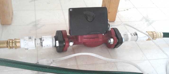
The circulation pump, set to "Low" flow.
The cast iron pump emitted a lot of rust until it
was spray painted inside with polyurethane spray.
The intake hose is a special one that won't suck closed,
collapse, from negative water pressure.
 Closing the fridge door at night to retain
warmth seemed like
Closing the fridge door at night to retain
warmth seemed like
a good idea at first... until I realized the fish would need air!
Light: Mirrors (but no smoke) and LED
lights (with smoke)
When the lettuce started sprouting, the leaves pointed
toward the window and they were spindly. There really wasn't enough
light. Lighting became a
focus because they'd die or at least grow poorly unless something was
done. (Several leaf lettuce plants sprouted, and just one counter
lettuce [similar to romaine]. The spinach didn't come up.)
On the afternoon
of the 27th, I set a mirror behind the plants. There was really no
sunlight, but it brightened things up. In a couple of hours I
noticed the leaves were pointed more toward the mirror. Making use of
whatever daylight is available may not be very high-tech, but it might
change things considerably. Instead of a mirror I can use aluminum
foil, and shape it to reflect light toward the plants - preferably from
above - during a good part of the day, or make a mechanism to have it
follow the sun. I put some foil around the inside of the drain-down bed
container and that pretty much used up what I had.
The lettuce sprouts were growing tall and spindly. They
definitely weren't getting enough light. On the 28th I tried a 5 meter
strip of LED RGB lights with remote control. I just draped it above the
plants, back and forth. But it wasn't very bright. On the 29th the sun
came out, and I aimed it via the mirror at the plants, which then
pointed towards the mirror. The strip light, which was still on, merely
cast a shadow in the sunlight. I finally removed it. But the mirror had
to be moved every few minutes to keep the bit of sun on the plants.
Also on the 29th I planted a few vegetables in the
drain-down bed. I'm not holding my breath, but I trust a few things
will come up. Usually I understand seedlings are planted in dirt and
transplanted to hydroponic beds later. Putting them right in the
beds I didn't have to water them.
I broke up the
second flat panel LED light I had made some
time ago and replaced the mediocre diffuser with a clear "cracked ice"
style diffuser I had bought. My impression is that the
diffuser is just adequate to make the pinpoint LED light sources
tolerable as building lighting for higher ceilings. I'd prefer the
translucent for wall mounting or lower ceilings.
But for grow lighting, clear transmits the most light, which the
plants crave. I'll also probably get better results with blue and red
emitters than white, and I expect to try them soon. Someone tells me
that with stationary LED lights, spots can get burned on the leaves, so
any diffuser would appear to be useful even with plants. (So would a
light that moves from east to west over the day!) He bought a one foot
square, 40 watt, blue and red LED grow light that he said was effective
at short range - a foot or two. Let's see... a 7" x 7" square light is
1/3 the area, and is about 12 watts, just under 1/3 the watts. Well!
With red and blue emitters, my prospective grow lights should be about
on par with these commercial units on an area basis, and at 30$,
cheaper for
the moment. The fact that mine are 12 volts DC should put them in a
slightly different market, tho of course a 12V power adapter is all
that's needed to make them 120VAC.
Then I wired a
12 volt dual CAT socket from the solar
panel system in the wall behind the fish tank, in an existing hole that
I made slightly taller for the electrical box. (I used one click-lock
socket just to see the effect. The flush ones of course look better.) I
put the light a couple
of inches over the lettuce plants. It still wasn't as bright as the
sun. It was the one made with 3.5 volt LED.s instead of 2.9 volters, so
it only had 15 emitters instead of 20, and the transistor gets quite
hot at 14 volts since it's dropping it to about 10.5, and so has 3.5
volts
across it. I returned after a while to find the light out: a trace on
the circuit board had burned out. I bridged it with a piece of copper.
It wasn't the hot transistor's fault: it was another result of the
Samsung CLP-315 color laser printer printing a hatched pattern where
it's told to print solid black. I won't use it for circuit boards
again! On the 30th, another dull day, the plants at last started to
turn up toward the lights just a couple of inches above. The area was
certainly the bright spot of the room.
On November 2nd the light fell into the fish tank. The
light kept working and no fish were harmed - a definite advantage of
LED.s and 12 volt power! (Of course, if it had been 120 V I'd have been
less nonchalant with it!)
Electricity Storage
Turquoise Battery Project
On the 6th someone in an e-mail said he was getting
self-discharge of his batteries similar to mine until he put them in
vacuum pack bags. It seems oxygen from the air was the cause of the
self discharge, and it's probably the cause in mine, too. I've made
some efforts to seal some cells, but they were half-hearted because I
didn't think air would filter in and absorb into the electrolyte water
fast enough to cause the problem. It also never occurred to me to take
note of the relationship between how good the sealing seemed to be and
the rate of self discharge. So I'm probably wrong and I'll try much
harder to get a good seal. I was of course disappointed to find the
lower voltage NiNi cells seemed to have at least as much self discharge
as the higher voltage NiMn, but if air is the cause the voltage
probably doesn't matter, so it seems likely that it is.
At any rate, assuming this is correct, the problems
with both NiMn and NiNi are simply construction problems, not
chemical problems. Making well sealed cells with sheet graphite current
collectors has been a headache - they can't be threaded like a bolt and
sealed with round grommets. But it's a "pre-production" detail, not a
basic research problem any more.
Perhaps another problem with using round jars for cells is
the amount of air already inside the cell, including that dissolved in
the considerable volume of water. Maybe I should go back to the thin
3D-printed cells? When I was doing those, I was getting deterioration
from using too much manganese oxides in the posode (with little or no
nickel oxides) and corrosion of the zinc current collectors, so the
cells didn't last. I may have better results if I try that format again
with nickel manganate posides and graphite foil current collectors on
both electrodes.
Next Posode
I decided to go with just Ni(OH)2 for the nickel. It's 63%
nickel atoms by weight. Using KMnO4 for the manganese (37wt% Mn), and
Mn being a bit lighter than Ni (54.9, 58.7), a 50-50 wt% mix should
give about 60-40 Ni to Mn, the desired ratio. The desired product is
nickel manganates, an insoluble, more highly conductive, and somewhat
variable product of Ni, Mn and O or OH. Since excess Mn will form
soluble KMnO4 on charge, it might be best to err on the side of excess
nickel, which will form NiOOH - the usual non-soluble charge product of
nickel electrodes. So I picked the ratio 55% Ni(OH)2 to 45% KMnO4. Into
that I'd add 20% (of the at last obtained) conductive carbon black for
conductivity
and about 2% Sm2O3 to help raise the oxygen overvoltage. So to make 100
grams, the formula becomes:
43g - Ni(OH)2
35g - KMnO4
20g - carbon black
2g - Sm2O3
Owing to the bulk resulting from the fluffy ingredients I
made 1/2 as much, 50 grams. (The samarium was 1.65g instead of 1.0
because I dumped out a little too much and wasn't putting it back in
the bag.) I mixed them up dry as usual in a jar and then added a little
Diesel Kleen and Sunlight dishsoap. Then I remembered I was supposed to
infuse them into graphite felt first.
I did what I could, but I the electrode resulting after 7
Mg (tons) of pressure was surely more graphite felt than active
ingredients, and the active ingredients were holding the 3 felt layers
apart. (to prevent good conductivity!)
Before assembling I painted the current collector
with calcium hydroxide, which I think will add more oxygen overvoltage
protection -- but I forgot to paint ferric chloride on the electrode.
These things come of working so infrequently on the project, and yet
still thinking I know what I'm doing, so I don't double check my own
instructions. Also, somewhere I often go into "autopilot" when I'm
working
and only think about the current detail, forgetting the broader picture.
Next Cell
 (23rd) I put
the two electrodes together with a 2 layer
macramé cloth separator. When I put them in the jar, I also cut
some pieces of polystyrene foam to take up much of the excess internal
space, so there'd be less water and air in the jar, since air seems to
be what causes the self discharge problem. Then I used silicone RTV
glue to seal the terminal slots as well as I could, rather than just
sticking some modeling clay over them. I filled the jar - maybe about
50mL of KCl solution - and tightened the lid.
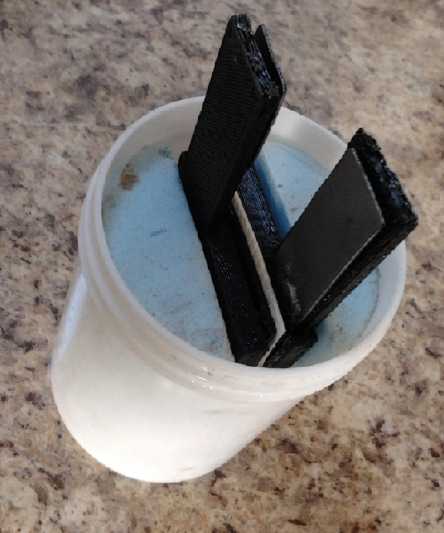
(23rd) I put
the two electrodes together with a 2 layer
macramé cloth separator. When I put them in the jar, I also cut
some pieces of polystyrene foam to take up much of the excess internal
space, so there'd be less water and air in the jar, since air seems to
be what causes the self discharge problem. Then I used silicone RTV
glue to seal the terminal slots as well as I could, rather than just
sticking some modeling clay over them. I filled the jar - maybe about
50mL of KCl solution - and tightened the lid.
The conductivity was so low I had to charge it at about
2mA, and still it went up above 2 volts. I decided it must be because
the posode was so thin it wasn't filling the box made for it. A new,
fatter electrode is probably the answer.
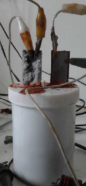 A few days on charge and it
held charge more and more poorly. Also salt
crept up the 'plus' 3D printed terminal post, showing that 3D printing
is "porous" and can't be used where a seal is needed. (Someone at
Makerspace "anneals" 3D printed plastic by heating it until it's soft
and runs a bit. This might work.)
A few days on charge and it
held charge more and more poorly. Also salt
crept up the 'plus' 3D printed terminal post, showing that 3D printing
is "porous" and can't be used where a seal is needed. (Someone at
Makerspace "anneals" 3D printed plastic by heating it until it's soft
and runs a bit. This might work.)
Being diverted by other things, I'll have to continue this
next month.
http://www.TurquoiseEnergy.com
Victoria BC