Turquoise
Energy Ltd. News #82
November 2014 (posted December 4th)
Victoria BC
by Craig Carmichael
www.TurquoiseEnergy.com
= www.ElectricCaik.com
= www.ElectricHubcap.com
= www.ElectricWeel.com
Features: Unipolar BLDC Motor &
Controller Progress (see "Month in Brief" and or detailed report)
Month In Brief
(Project Summaries)
- Unipolar motor controller circuit & circuit board -
aquaponics & LED lighting - variable torque converter transmission
- Coursera.org's "Wind, Waves and Tides" renewable energy course -
Electric Mazda & EV Mixed Batteries update - a small peltier fridge
update: it works better in cold weather.
In Passing
(Miscellaneous topics, editorial comments & opinionated rants)
- The Need to Enable Citizen Initiated Binding Referendums - Need
and Reasons for the Coming Collapse?... Superficial People Elect
Superficial Leaders.
Electric Transport - Electric
Hubcap Motor Systems
* Unipolar BLDC Motor & Motor Controller Project
Other "Green"
Electric Equipment Projects
* Aquaponics & LED Grow Lighting Project - 7" x 7" plant growth
light
Electricity Generation
* Wind Power: some VAWT calculations and schemes
* Wind Powered Vehicle goes straight downwind 3 times faster than the
wind! (Honest!) ...EV applications?
* Woodstove Thermoelectric Generator? - nah.
Electricity Storage - Turquoise Battery
Project (NiMn, NiNi), etc.
* New Soldered "D" cells, 100AH 12V NiMH batteries for RX7 EV etc.
* Real Lead-Acid - and NiMH - Capacities?
No Project Reports on: Turquoise
Battery Project (rats, no time!), Lambda
Ray Collector, Magnet motor,
evacuated tube heat radiators, CNC gardening/farming machine.
November in Brief
I thought I could get the unipolar BLDC Electric Caik
motor running in November and put considerable effort into it, and
towards the end of the month it became clear that it wouldn't be ready,
and I turned to some miscellaneous other things that weren't getting
done. I also did some aquaponics and LED lighting work trying to
prevent the plants from croaking and get some vegetable production
going.
Unipolar Electric Caik Motor
I did more work designing the circuit for the unipolar
motor controller and then the circuit board artwork. Some things being
quite critical, I carefully arranged
the
components and laid out the tracks by hand in the Eagle circuit
board CAD program. I thought I had it done on the 16th, but made a few
final changes in the next two mornings, and later had to change it
again when I found the 4000B CMOS NOR gates logic chip I chose is
unavailable. It's been superceded (probably long ago) by the 4025B.
Unipolar BLDC Motor
Controller - printed circuit board artwork (bottom side)
with scattered voids from crappy printer
 Meanwhile, on
the afternoon of the 16th I tried
printing
out the pattern for the bottom of the board (as it then was) on my
other printer. (The other one printed fine patterns instead of black,
explaining many of my PCB making problems.) I printed it on the "toner
transfer paper" and transferred it to a piece of circuit board. The
first one was abysmal. It looked bad, and some areas didn't stick to
the copper. They just floated off, even after running it through the
laminator a dozen times. I ran a drum cleaning cycle on the printer,
positioned the print in the middle of the page instead of on one side,
and tried again. It was much better, and I ran it through the laminator
in a different direction on each pass. This time there were no loose
toner patches, but there were little missing bits all over. It's the
printer. I need to find a better one to use or buy.
Meanwhile, on
the afternoon of the 16th I tried
printing
out the pattern for the bottom of the board (as it then was) on my
other printer. (The other one printed fine patterns instead of black,
explaining many of my PCB making problems.) I printed it on the "toner
transfer paper" and transferred it to a piece of circuit board. The
first one was abysmal. It looked bad, and some areas didn't stick to
the copper. They just floated off, even after running it through the
laminator a dozen times. I ran a drum cleaning cycle on the printer,
positioned the print in the middle of the page instead of on one side,
and tried again. It was much better, and I ran it through the laminator
in a different direction on each pass. This time there were no loose
toner patches, but there were little missing bits all over. It's the
printer. I need to find a better one to use or buy.
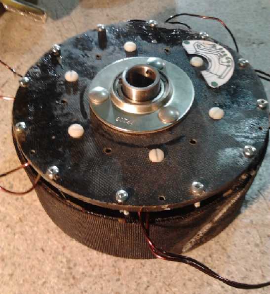
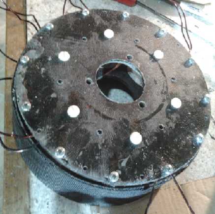
Caik Motor
assembled with 1/4" nylon bolts in the coil centers.
 Sometime I
decided to use the second Electric Caik Motor body, which I had made as
an extra when I first developed that size motor, and make a completely
new unipolar one, rather than 'renovate' the old one for the first
unit. I was going to use a new pattern of bolts to clamp the body
pieces together, one which included nylon bolts ('machine screws')
through the coil centers to reduce magnetic heating of metal bolts. At
first I was going to use metal bolts in the outer ring... but even
there they would probably get a little warm, so plastic would doubtless
be ideal -- if it was strong enough so no threads would strip.
Sometime I
decided to use the second Electric Caik Motor body, which I had made as
an extra when I first developed that size motor, and make a completely
new unipolar one, rather than 'renovate' the old one for the first
unit. I was going to use a new pattern of bolts to clamp the body
pieces together, one which included nylon bolts ('machine screws')
through the coil centers to reduce magnetic heating of metal bolts. At
first I was going to use metal bolts in the outer ring... but even
there they would probably get a little warm, so plastic would doubtless
be ideal -- if it was strong enough so no threads would strip.
On the 20th and 21st I did the drill template for the body
bolts/screws. On the first template the ring of outer holes didn't
look like a very good fit. I made a second one and then drilled
the holes using it. I test-fitted the stator side together and the
nylon coil center machine screws seemed satisfactory. I put in 10-24
metal screws around the outside, but later I decided to use entirely
nylon machine
screws for the stator body side. I couldn't get #10-24 nylons long
enough to do the outside ring - in fact, an inch was the longest. I
ordered 1/4"-20 x 2.5" instead, and will have to see how they fit.
They'll take up a good portion of the total thickness of the outside
wall, making weaker spots. Maybe I should look for some #10-24 or M5 on
the web.
Aquaponics & LED Grow Lighting
First I had a little disaster with pH.es not being what
they seemed, and lost half the tilapia fish in an hour, presumably to
high pH. Two jumped right out of the tank onto the floor. That saved
the others, because I wouldn't have noticed their distress in time if I
hadn't gone into the room and seen them lying there. I had added a
couple of teaspoons of calcium and potassium, after which the pH strips
said "7" instead of "6", and I thought I had finally neutralized it.
Afterward I checked and tap water also read pH 6. I thought the strip
colors were off. Afterward I got an aquarium pH indicator, but it said
about the same thing. So now I leave the pH reading well enough alone,
at "6" or "6.2". I thought that was acidic.
Two of the remaining three seemed to become lethargic, and
flighty if disturbed. (I replaced the other three on December 2nd when
the dealer got them in for me.) The fish make a lot of poop that
settles on the bottom, and I have to clean it out of the center-bottom
of the sump tank every couple of days, and what doesn't circulate out
of the fish tank once in a while. I can see having the tank on top and
draining into the plant beds is a better arrangement since the waste
automatically goes to the plants.
 I planted
vegetables in the drain down bed. What started growing best was kidney
beans (scarlet runners?) and peas. But it was obvious there wasn't
anything like enough light through the window in the winter. I read in
Indoor Growing magazine that the biggest mistake beginners make is in
underestimating the amount of light required.
I planted
vegetables in the drain down bed. What started growing best was kidney
beans (scarlet runners?) and peas. But it was obvious there wasn't
anything like enough light through the window in the winter. I read in
Indoor Growing magazine that the biggest mistake beginners make is in
underestimating the amount of light required.
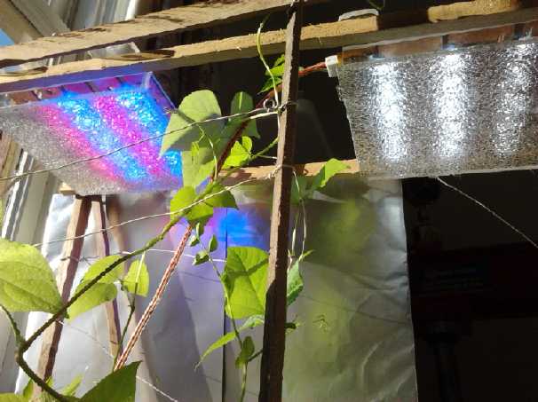
I got one blue-red emitters
flat panel LED light made, and I put it over the aquaponics drain-down
bed, now the only plant bed, to give the spindly plants some light. I'm
very pleased with it and I started thinking again about producing LED
lights, both white space lighting and blue-red plant growth lighting.
Human eyes are most sensitive to green, and so it seems non-intuitive
that these dull looking blue-red lights are actually brighter than
white at the blue and red light frequencies that plant leaves use. A
friend says I'll have the police here soon with a blue-red light
showing in the window, looking for marijuana. It hasn't happened yet.
(I'll say more on the subject of marijuana as an example of the need
for the right of all citizens to initiate binding referendums in "In
Passing".)
By varying my search terms
I located and ordered some 410-415nm
(nanometers wavelength) and 420nm LED emitters - more centered in
the 400-450nm photosynthetic range than the 445-455nm ones I found
before. The visible spectrum is about 390nm to 700nm. 400nm verges on
the near ultraviolet.
Of course the tilapia seller also had an aquaponics setup.
He had a fat disk shaped 50 watt LED grow light about 7" in diameter.
It ran on
120VAC and the top part enclosed a fan that cooled the emitters and
electronics. You could feel the heat on your hand under it. He
said it cost about 70$. That's some stiff competition if I have to
charge 50$ to make my 15 watters viable. OTOH if I add fan cooling to
mine I can up the power and light density quite substantially (double
or better?) in the same space for 15 or 20 extra dollars.
I also made a featherweight mirror of coroplastic and
aluminum foil.
So far I haven't found a ball joint thing so I can mount and deploy it
in front of the windows at any angle to beam any sunlight there may be
onto the plants. More lights will be needed, and more places to plug
them in.
On the 30th I designed a fourplex CAT sockets 12V wall
plate for a regular 1110 electrical switch/plug box, in OpenSCad. I
haven't yet printed it on the 3D printer. When I get up to over 4 LED
lights to plug in in one place, I'll do a 6-plex. 6 CAT receptacles
should still fit in the available 1110 box space. And maybe I'll try a
new style with the receptacles built into the plate instead of being
inserted later. It might look better. The wire sockets would slip in
from the back and then a rear cover would screw over each receptacle to
keep them from popping out.
Variable Torque Converter Transmission
In working on the Unipolar
Electric Caik motor project, I barely found time to mount the
centrifugal clutch, and that only because I wanted to put it all
together and
clear it off the workbench. The only remaining obstacle to completing
the assembly is that the planet gear is 1.064" I.D. and the shaft in
the motor is 1.0". I made a shaft with a 1.064" end previously, but
it's too short as now configured and I haven't found a shaft "blank" to
make another, longer one. So it'll need some sort of shim.
And if the unipolar motor and controller works anything
like as well
as I hope, I'll be wanting to make them for the car as well, before I
bother trying to put everything together, rather than set up the Kelly
controller and get everything configured and working only to very soon
want to change it. Thus the new priority of the unipolar motor
project over the transmission. (I guess I spent hundreds of dollars on
the 300A, 36V Kelly
bipolar BLDC controller just to see an important feature of the power
transistors layout to use in my own design.)
Coursera.org and "Wind, Waves and
Tides" renewable energy course
 Correction: In the
last
issue I said that savonius rotors only made 60% of the power from the
same wind frontage as a propeller type. That didn't look right for 32%
over 47% per the diagram, so I calculated again later and the correct
figure - going just by the graph - is 68% - about 2/3.
Correction: In the
last
issue I said that savonius rotors only made 60% of the power from the
same wind frontage as a propeller type. That didn't look right for 32%
over 47% per the diagram, so I calculated again later and the correct
figure - going just by the graph - is 68% - about 2/3.
Perhaps with a wind funnel/shield it can be still better,
and for light winds or gusty shifting winds it's surely "the" choice.
If the vanes are only turning the speed of the wind, it should
be much quieter - a big asset in an urban or suburban area and thus
again "the" choice. I also note that the darieus, harder to build and
use and inherently less sturdy, is only 12% better, so the savonius
again looks like a better choice.
But I think a good blade design for a hybrid
"savonius-darieus" could turn at double the windspeed or better, which
ups the theoretical power available considerably.
The wind data for my area, from Environment Canada and
pointed to by the lecturer, seemed pretty discouraging - which I
already knew from living here. But there's more wind in the winter when
solar is pretty useless, and much of the month had at least some
breeze if not wind.
I did some more looking into and thinking up design
details for a VAWT for the house roof as the breezes blew and the
overcast sky prevented much of any solar power from happening. Near the
end of the month I got an e-mail titled "Last Week of Wind, Waves and
Tides". Alas, I've fallen way behind and I'll have even less time to
finish it in December.
Electric Mazda & EV Mixed Batteries update
As cooler weather arrived, I again found
the e-RX7 again using substantially more energy per mile. From under
1.9 amp-hours/mile (@140V) it rose to 2.0 and then 2.2 to 2.5 and
beyond, even 3 on short trips. I found the tires all down to
about 28 PSI and I inflated them to the max, which was 35 PSI except
for one that, to my surprise, said 44 PSI. It wasn't the whole
difference, but it seemed to bring it down some - maybe 10% better
range. Perhaps I should find 3 more of the higher pressure type.
Obviously tires make a big difference. I wonder what can
actually be done to reduce tire losses without them losing road
traction.
I've seen a number of ideas for better, mostly airless, tires published
over the years but none seem to be on
the market. Did they all have problems, or are better types of tires
being kept from us by the corrupt? For example, what about polyurethane
or a rubber/polyurethane blend surface to provide better traction per
square
inch, which would then require less road contact area? It could even be
a solid sponge rubber
needing no air.
As for the rest of the performance reduction, perhaps some
greases and oils that stay thinner or slipperier at cool temperatures
need to be created, found or spec.ed for winter driving. Better still,
get rid of the lossy
transmission.
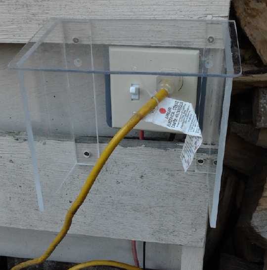 With the
cooler, wetter weather also, I recalled that the
switch I had to turn off the plug the car was plugged into, was a
regular single pole switch. But the inverter from the solar collector
puts voltage on both the line and the 'neutral' wires. One day a while
back I had seen the neon light at the end of the extension cord at the
car glowing with the switch OFF. This was an evident electrocution
hazard, so I bought a double pole switch. However, I had placed the
switch under the shelter of a firewood shed and in the meantime had
filled that with firewood. I had left a place to reach in, but I
couldn't replace the switch. Now that cooler weather has arrived, I
started using the firewood and I pulled some more out to access it. I
replaced the entire thing with a new box, the switch and a duplex
receptacle.
Then I thought to mount it on the outside of the wall instead of
inside, and make a box to keep rain off it.
With the
cooler, wetter weather also, I recalled that the
switch I had to turn off the plug the car was plugged into, was a
regular single pole switch. But the inverter from the solar collector
puts voltage on both the line and the 'neutral' wires. One day a while
back I had seen the neon light at the end of the extension cord at the
car glowing with the switch OFF. This was an evident electrocution
hazard, so I bought a double pole switch. However, I had placed the
switch under the shelter of a firewood shed and in the meantime had
filled that with firewood. I had left a place to reach in, but I
couldn't replace the switch. Now that cooler weather has arrived, I
started using the firewood and I pulled some more out to access it. I
replaced the entire thing with a new box, the switch and a duplex
receptacle.
Then I thought to mount it on the outside of the wall instead of
inside, and make a box to keep rain off it.
Finally, the two 'size 24' PbPb batteries started getting less and less
range, seemingly with each passing trip, and I took them out. They
lasted only about 18 months in spite of having sodium sulfate added to
them when new. They can probably be renewed... if done carefully... but
when all was working fine
they were always the range limiting batteries. Maybe I'll use them to
increase the solar storage instead of putting them back in the car.
I decided to replace them with soldered-up NiMH D cell
batteries. I figured out that if I soldered them together one
particular way, I could fit two 100AH, 12V NiMH batteries where the two
smaller size 24.s (about 85 rated AH and lower current capacity) were
previously the only ones that would fit. I had enough D cells here and
there to scrounge up for one battery and half of the other (using the
ones for the boat and most everything else). The other one has cost
500$
for 50 new D cells. But this was part of the mixed battery idea: to be
able to replace poorer batteries - or poorer types of batteries - with
better ones individually rather than incurring a huge bill to do them
all at once.
I also plan to redo the 90 AH pipe batteries by
soldering those cells into new 100 AH batteries for better reliability
and smaller footprint. I'll then have five 100 AH, 12V NiMH dry cell
batteries. Or to be more exact, I'll have ten 50 AH, 12V batteries,
which I'll double up.
These will of course be transferable to the Chevy Sprint
with a longer-range unipolar Electric Hubcap motor & controller,
the ultra efficient
variable torque converter transmission, perhaps with solar panels or
VAWT on
the roof, when - and presuming - the time comes. For 36 volts they'll
be be configured as three 150 AH, 12V batteries with one spare 50 AH.
(Those will probably be augmented for more range by PbPb.s (with diode
isolation), perhaps six 6V golf cart batteries of over 200 AH each.)
And presumably someday the batteries will all be replaced with
nickel-manganese or nickel-nickel "everlasting" batteries. If the
unipolar motor is as good as hoped, giving a potential range of 300
miles or more without driving around in a giant tank of batteries, the
question arises as to whether it's still worth trying to hybridize a
gas car.
I've made one, but obviously I have a lot of soldering and
battery assembly ahead of me. Soldered packs are dangerous if they
don't have paper wrapping the cells: the thin plastic covers can melt
or wear off, then the cell cases short circuit together and really
start heating up, destroying the pack... and at worst might potentially
cause injury or burn down the building they're in. "Cordless" power
tool batteries all have paper/cardboard wrapping around each cell. And
yet, companies will sell you individual cells with welded tabs intended
for soldering into packs: with no paper wrapping. I made several
unprotected packs out of ignorance - and all of them I either took
apart again or they burned up. (3 burned IIRC.) Companies in the
battery business surely know better, so selling them that way seems
irresponsible. And I'd probably have avoided the mistake myself if I'd
seen "with tabs and cardboard wrapped for making battery packs" on the
batteries for sale.
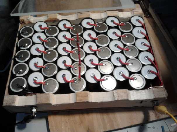 One new
100AH battery would get the RX7 EV on the road again at least for short
trips. I started the ball rolling on the night of the 24th by cutting
150 tarpaper wrappings for the first 150 cells, then wrapping the first
50 of them - one battery's worth - by 1AM. The next day I made a vented
wooden box to hold 50 D cells - one battery, a little jig to cut all
the wires to the same length, cut and stripped them, and soldered up
the 5 strings of 10 cells for the first 50AH 12V battery with #16
stranded wire. At noon I stopped for breakfast. I finished the battery
about supper time. I can improve on the build time somewhat (since I've
got the nuts and bolts now), but not a whole lot.
One new
100AH battery would get the RX7 EV on the road again at least for short
trips. I started the ball rolling on the night of the 24th by cutting
150 tarpaper wrappings for the first 150 cells, then wrapping the first
50 of them - one battery's worth - by 1AM. The next day I made a vented
wooden box to hold 50 D cells - one battery, a little jig to cut all
the wires to the same length, cut and stripped them, and soldered up
the 5 strings of 10 cells for the first 50AH 12V battery with #16
stranded wire. At noon I stopped for breakfast. I finished the battery
about supper time. I can improve on the build time somewhat (since I've
got the nuts and bolts now), but not a whole lot.
Finally, here's a small update on the peltier module
fridge: With winter here, in the now quite cool kitchen the same
peltier
module that couldn't keep the fridge
below 6 to 8°C in the summer and made only a little ice is freezing
the whole ice tray solid and lowering the fridge temperature near the
ice tray to 3, 4, or 5°. It can now be turned off for several hours
without melting all the ice. In attempting to evaluate the
effectiveness of
different peltier modules and combinations of modules, I'm sure I
haven't
been taking the room temperature sufficiently into account.
In Passing
(Miscellaneous topics, editorial comments & opinionated rants)
The Need for the Right to hold Citizen Initiated Binding Referendums
On the whole Pacific northwest coast, BC now stands out as
being the only jurisdiction in which marijuana is still illegal, with
Alaska, Washington and Oregon having dropped prohibitions against it.
This example shows the difference between where citizens can
create a binding referendum relatively easily and where we can't,
because there's little doubt the laws against marijuana would also have
been rescinded in BC if we should have a vote on it. In fact, if people
had the
right to create referendums before the time such laws had been enacted,
they
probably would never have been, or they would have been quickly
canceled by
the populace.
While I'm here... marijuana laws have some interesting
history. Many people are unaware that the push to ban marijuana was by
the cotton growing lobby. It had nothing to do with impartial reasons
or studies of a medical or law enforcement nature. The cotton lobbyists
reasoned that if they could get the government to ban marijuana, for
which its properties and effects on its users were merely a pretext,
when marijuana and hemp are virtually the same plant and can't be
easily distinguished, the government would have to ban growing of hemp
as well. Hemp was a big industry. It is in many ways a better fabric
fiber than cotton and the seeds are nutritious. (They contain no THC.)
The American Constitution is written on hemp paper. Thus at a stroke,
they eliminated the main competitor to cotton. And they created a
monster. Money and monopoly is the reason for more problems than one
realizes - "Follow the Money!" "Greed is the root of all evil."
Before world war two, marijuana was purportedly illegal
(I'm paraphrasing) 'because its users become aggressive and violent'.
During the war it was legalized again because the government wanted
aggressive, violent soldiers. After the war it was made illegal again
'because its users become passive and have no initiative'. That this is
the opposite of the original reason shows how casually laws may be
enacted that deprive people of rights and freedoms, that emotion and
sentiment rather than facts often rule. And they rule with an iron
fist. How much tax money is spent attempting to enforce marijuana laws?
How has it distorted the justice system? How many innocent people,
having not robbed, cheated, assaulted or otherwise victimized anyone,
are in jail for simply possessing of a bit of this sought after and
medicinal plant that grows naturally in warm climates? Do the cotton
growers care about that? What fine organic hemp products do we not have
available to us today?
But marijuana is just one of countless instances of
government meddling in peoples' private affairs that infringe on
peoples' rights and freedoms to no good cause, on behalf of
profiteering monopolies or would-be monopolies.
Old laws, good or bad, are rarely retracted because
politicians don't want to spend time reviewing past decisions from
before (or even during) their time, which would require looking into
all the possible reasons the legislation might have been enacted and
might still have a purpose, versus the reasons it might now be
irrelevant, harmful or should never have been enacted in the first
place. That would require study of the subject to a depth deeper than
in the original often casual passing of the legislation. Since new
regulations are made at the drop of a hat, often to solve some small
real - or perceived potential - specific problem in one situation
without regard to the fact that they will be applied everywhere to
everyone in every situation, until one can hardly turn around without
breaking a law.
As an example, a municipality near here which shall remain
nameless didn't want trees on a new subdivision to be cut down. They
passed a law requiring a permit to cut down any tree in the
municipality. I thought "That's outrageous! I'm sure glad I don't live
there!" I've probably cut down about 20 trees on my property over the
many years I've lived here. And some new ones have grown, planted by me
or volunteers. They grow, and eventually they need to go. I don't need
somebody from the city to tell me when it needs to go, or worse, have
them deny my "request" to be allowed to remove it.
But soon every local municipality, like robots, passed the
same law! There was no discussion and no public hearings or other
input. Now homeowners live in fear of a municipality - that was created
in the first place to serve them - and which their ever increasing
property taxes funds. The penalty for cutting down a tree on your own
property without a permit is $10000! That's much greater than for
cutting down a tree on public property, which is only considered a
"misdemeanor". Congratulations, the government has usurped control of
YOUR land and garden, and has hired more civil servants at your expense
to do so! And, showing how insidious laws become once enacted, a young
arborist said to me "We need that law, or else everyone would cut down
all the trees." I pointed out to him that there were no fewer trees
before the law than after, and that except for the youngest, the
present trees had been there since long before the law was made. In
addition, people would now be leery of planting trees or letting them
grow because they wouldn't want to lose control of their property to
the municipality. That's after less than 10 years. After 20 or 30,
everyone might
think the arborist was right, or at least had a good point, and it will
be almost impossible to get politicians to delete this absurd law.
However, I doubt the law would stand in a vote by house
and land owners. Just maybe I could be wrong... I can't see it. Either
way everyone would know it's the peoples' decision and not just a few
flakey politicos doing it because somebody else did it. There's why
citizens need to be able to initiate referendums - at every level of
government.
Publicly initiated referendums are a means to start
redressing the imbalance between what's needed and what elected
officials are inclined to do.
"If there were ten thousand laws, it would destroy respect for law." -
Winston Churchill.
Need and Reasons for the Coming Collapse?
Individuals make the world. There seem to be a
lot of people on this one who seem to be superficial and shallow.
They'll believe and think what they're told without any effort at
rational examination or logical consistency. In 12 or more years
of education, they haven't been taught to think critically,
analytically, and independently. They're "politically correct" and
asleep. Perhaps they're more interested
in the latest episode of some TV show, a computer game,
or they fly from one form of entertainment or distraction to another.
They seem to live somewhat removed from
real life and give it little attention. Or they're in economic hardship
and considering how to improve their world isn't on their radar screen.
Recently I heard that public opinion polls
show that the great majority, after a few 'beheadings', much contrary
to pre-ISIS polls, now support the US military going back in -- to help
eliminate ISIS. But there seems to be considerable evidence that the US
bombings are dropping supplies
to
ISIS ("Oops it was an accident") and bombing Syria's infrastructure.
This would appear to still be following the same worn
agenda Washington has consistently pursued for almost the whole of this
century, and Washington is still saying, now
incongruously to the purported reason for invasion: "Assad must go!"
Like Sadam Hussein and Moammar Qaddafy(sp?), Assad isn't knuckling
under to Washington's demands. 1/2 the population of Syria
was already refugees before ISIS. That majority of Americans who've
changed their minds over a few beheadings and murders
don't seem to mind that the US military has killed
a million people in the middle east over a decade, and many thousands
in "impersonal" drone strikes in various places.
"Negotiating with
Washington
is
like playing chess with a pigeon - the pigeon knocks over the pieces,
sh*ts on
the board, and then struts around like it won the game." - Vladimir
Putin
And even in municipal elections here a few days ago, the
poll topping
alderperson was one who went to "campaign school" and was taught that
you should never say anything of substance, take a stand on
anything, or make any promises. (I heard this from her aunt, who I
know.) When you speak, something you say or believe in
is bound to offend someone. Your opponents will then hype that up
(often out of context) and use it against you, and the shallow public
will then vote against you on that
basis regardless of anything and everything else you've said and done
and stand for -
which will be given no publicity whatsoever. So the superficial voters
elect a
bunch of superficial wishy-washy non-entities who stand for nothing,
have no idea how to help their society, and
just like the idea of money, power and prestige. Real leaders don't
have a prayer of being elected, because there aren't enough people
paying real attention!
Add to this the seemingly gradually deteriorating human genetic base of
which I wrote last month, and one might start wondering how things can
possibly be fixed.
POST TURTLES
While stitching a cut on the hand of a 75 year old farmer,
whose
hand was caught in the squeeze gate while working cattle, the
doctor struck up a conversation with the old man.
Eventually the topic got around to politicians and their
role as our leaders.
The old farmer said, "Well, as I see it, most politicians
are 'Post Turtles'.''
Not being familiar with the term, the doctor asked him
what a 'post turtle' was.
The old farmer said, "When you're driving down a country
road and
you come across a fence post with a turtle balanced on top, that's a
post turtle."
The old farmer saw the puzzled look on the
doctor's face so he
continued to explain. "You know he didn't get up there by himself, he
doesn't belong up there, he doesn't know what to do while he's up
there, he's elevated beyond his ability to function, and you just
wonder what kind of dumb arse put him up there to begin with."
- Author unknown
 All those sleeping,
superficial people will have to either wake up
sometime
soon, or risk going down with the ship. I know I keep saying the
financial system will implode et al and it hasn't happened yet. It
could start tomorrow or it could perhaps still be two or three years
off. If the Swiss had voted to back their currency 20% with gold on
November 30th, which would have required Swiss banks to buy over 1000
tons of gold [evidently non-existent in the west], it might have been
triggered. But the
"bankers get rich" ponzi scheme that is the global financial system is
unsustainable and there's no political will or plan to make the major
and fundamental changes that might prevent collapse. And the
ever-growing population puts a great strain on resources. Some
economists
are saying (eg, on youtube) it's starting to look like almost
everything
everywhere is reaching its limit.
All those sleeping,
superficial people will have to either wake up
sometime
soon, or risk going down with the ship. I know I keep saying the
financial system will implode et al and it hasn't happened yet. It
could start tomorrow or it could perhaps still be two or three years
off. If the Swiss had voted to back their currency 20% with gold on
November 30th, which would have required Swiss banks to buy over 1000
tons of gold [evidently non-existent in the west], it might have been
triggered. But the
"bankers get rich" ponzi scheme that is the global financial system is
unsustainable and there's no political will or plan to make the major
and fundamental changes that might prevent collapse. And the
ever-growing population puts a great strain on resources. Some
economists
are saying (eg, on youtube) it's starting to look like almost
everything
everywhere is reaching its limit.
Things that are being put onto people seem to me to be
ever more desperate and lawless, with the big banks and governments in
collusion and protected by the police who should be arresting the
ringleaders. Look around at negative interest rates
on
savings accounts in Europe, 'random' thefts of individuals' larger
value
bank accounts by the IRS in the USA, "capital controls" (can't withdraw
your own money except in small amounts) in some European countries,
"bail-ins" (bank account theft) in Cypress and and
then legislation for doing the same thing in many countries "if
necessary" (including in
Canada), investment and retirement funds pillaged, and the
incomprehensible sums of currency being printed or
just
conjured up on computer screens in countries everywhere. Look at
governments actually admitting they want inflation - to reduce
the impact of their staggering debts... which BTW also robs your
savings of their value. Who would have dreamed of such things, and not
risen up in indignant revolt over them, 15 or 20 years ago?
Look at government statistics, calculated in more and more
"creative" ways to produce satisfactory numbers for public consumption
through the propaganda networks, and the manipulations in every
market, setting values arbitrarily to try to convince the sleeping
public that everything is fine, when each year higher and higher
percentages of whole populations have more marginal or no employment as
economies contract.
It's said that nearly 100 million Americans, practically 1/3 of the
population, are collecting some form of government assistance. The
entire world economy is shrinking. Shipping tonnage is way down. Only
the top few percent are prospering,
and of those, mostly it's the 1% of the 1% of
the 1%. It was recently said that 85 individuals have as much wealth as
the entire lower half of the world - 3.6 billion people. In feudal
times the inequality of wealth distribution was probably never so
great. Then look at all the
debts, immensely larger than all the money in the world. How can they
ever be paid back, when all new money is borrowed into existence,
adding more debt due back with interest? Debt, increasing debt,
economic slavery, for everyone, forever?
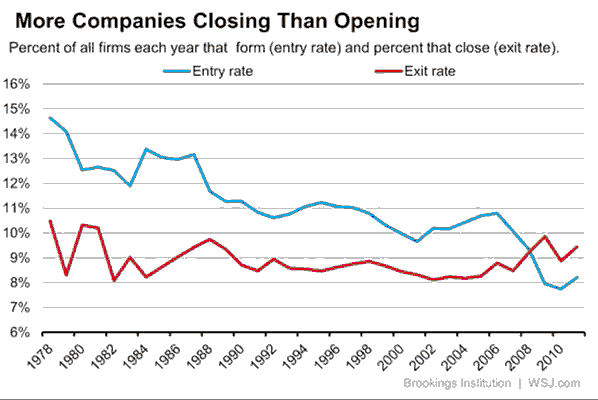
What's all this doing to the economy? An independent
company can't prosper in a corrupt and increasingly impoverished
society, because any who still manage to prosper without being part of
the corrupt establishment oligopoly become targets for wealth
confiscation. This itself ensures eventual collapse of the economy and
the society. Here's a graph of businesses starting and ending. It's
American and a bit dated but by all accounts things are generally
getting worse,
not better, pretty much everywhere. One sees that the new businesses,
the ones that bring innovation, new industries and new employment, have
mostly stopped happening. Some of the businesses closing in the last
few years have been big store chains and established manufacturers,
representing massive layoffs and decrease in economic activity. (I
don't know if individual stores of a chain are counted - many chains
apparently have closed some but not all of their stores.) And there's
probably lots of "for lease" and "for sale" vacant commercial spaces in
your town, too - the signs are there, literally. And the "money
velocity", the rate at which money is changing hands in sales and
purchases, is at record lows.
Of course, the usual
alternative for storing wealth if one
doesn't trust fiat currency or the markets that operate through fiat
currency is precious metals. Mike Maloney ("Hidden Secrets of Money"
video series) says that as trust in a fiat currency dies, gold always
"does an
accounting" of it. That is, the price of gold rises until it takes all
the available fiat currency to buy all the available gold, and the
price rises sharply. In 1971(?) when the US$ was taken off the gold
standard, gold went from a heavily undervalued artificial price of 35
$/ozt, to 800 $/ozt. (ozt = troy ounce - or as prefer to call it, a
trojan ounce, at 31.1 grams somewhat more than a regular ounce,
28.34g.) After that, with the dollar surviving the transition, it had
become overpriced and dropped to 400$ - till over 11 times what it was
before. (Bitcoin is
a new wild card. It probably won't collapse with every other fiat
currency because it can't be printed to death. With little physical
gold to be had, it may do some of the "accounting" and fly up in price.)
Of all people, Allan Greenspan is going around advising
everyone to buy physical gold. But people were taking his advice before
he said it, as sales of gold and silver (just as good) bullion are at
record levels
and more countries are trying to get their hands on all the gold they
can find. According to big dealers like Rob Kirby (KirbyAnalytics.com),
the COMEX and LBMA spot price of gold - what you pay for an ounce of
gold at a coin shop - is now subsidized, as part of the manipulation to
make the US$ look good. But if you want a large quantity such as a ton
of actual gold, and if you can find it (somewhere in Asia?), be
prepared to pay not 1200 US$/ozt but 1800-2000 and up. And you may not
find it unless you offer a lot more. Kirby said he and his brother,
about 10 years ago when gold
was 300 $/ozt, happened to get matched up with a retired chairman of a
Swiss banking institution in Canada while playing golf in Toronto. As
they played the
conversation turned to the markets and the banker asked them what they
thought was a good place to put money for the future, and they said
they'd like to be in the gold market. The banker said "If you knew how
much effort and how much resources have been put out by the
central bankers around the world into discrediting gold, you wouldn't
be
nearly as bullish as you are now!" ...The banksters don't want people
"opting
out" by choosing a form of wealth outside their control!
Even before money comes food and living supplies. Once
organizational structures and supply chains are disrupted and
governments are unable to respond well and quickly, this overpopulated
planet will almost inevitably face hunger, which will herald a pandemic
or even multiple pandemics until the number of living people is much
reduced. Most likely such disease(s) will start in the crowded parts of
Asia and Africa. Fast travel will carry them around the world. The
"black death", which probably included a hemorrhagic fever like ebola
as well as bubonic plague, killed over 1/2 the population of Europe in
a few decades, and while we have come a long way in treatments and
cures since then, we know that fast 'mutating' viruses like influenza
are very hard to control, much less stop, while vaccines for it are
often of dubious value. (I remember reading long ago that two distinct
forms of the "black death" were recognized, 'contact' and 'airborne'
forms, which behaved differently with different rates of progress and
different survival rates, the 'airborne' (if you were coughed on by a
sick person) being far more deadly. I infer it was probably ebola or
something like it.)
After all this trouble, when the problems that were
unleashed by low moral standards, by allowing unscrupulous hidden and
uncontrolled power to arise, and the folly of allowing unlimited
population growth on a finite planet, become exposed and generally
understood, a glorious new world awaits -- if the remaining individuals
heed these lessons, and cause education and the new global society to
conform to principles of
higher morality, philosophic ideals and spiritual values than
presently. Humble as it may seem, it still comes down to each
individual. And some of what each individual is and does depends on
their upbringing, and on their real education.
Newsletters Index/Highlights: http://www.TurquoiseEnergy.com/news/index.html
Construction Manuals and information:
- Electric Hubcap Family Motors - Turquoise Motor Controllers
- Preliminary Ni-Mn, Ni-Ni Battery Making book
Products Catalog:
- Electric Hubcap 7.2 KW BLDC Pancake Motor Kit
- Electric
Caik 4.8 KW BLDC Pancake Motor Kit
- NiMH Handy Battery Sticks, 12v battery trays & Dry
Cells (cheapest NiMH
prices in Victoria BC)
- LED Light Fixtures
(Will accept BITCOIN digital currency)
...all at: http://www.TurquoiseEnergy.com/
(orders: e-mail craig@saers.com)
Daily
Log
(time accounting, mainly for CRA - SR & ED assessment purposes)
4th: Worked on Unipolar Motor Controller PCB
5th: Tried alkalizing fish tank water a bit. Cleaned up aquaponics
disaster, saved remaining 4 fish. Worked on Unipolar Motor PCB.
6th: Worked on Unipolar Motor Controller PCB
13th: Replaced box, switch & socket for EV charging for safety
reasons. (live neutral from solar inverter)
14-15th: Investigating VAWT parameters, transport applications for
VAWT.s: (EV.s could partly or fully power themselves from an enclosed
VAWT on the roof on windy days, regardless of wind direction!)
15: Worked on Unipolar Motor Controller circuit (power supply) design,
PCB artwork
16: Worked on Unipolar motor Controller PCB. Test printout of artwork -
poor results; may need new laser printer.
17, 18: Touch-ups of Unipolar Motor Controller PCB artwork; started
G-Code for Unipolar Electric Caik Motor; started Caik optical rotor
position board layout.
19: Finished rotor position PCB design. Continued G-code.
20: Continued G-Code and started it for Electric Weel as well.
21: Finished G-Code, made Caik drill template with CNC router (after
two tries), and drilled some body bolt holes and test fitted them.
Glued two pieces of 'lexan' together for Electric Weel drill template.
22: Set up pea, bean and LED light supports (wood, rod, wire...);
Cleaned printer and printed PCB pattern for optics board. It still had
random white spots, voids, in the black areas. Decided to liason with
Microsec R & D on Monday, where Ed makes very good boards with the
same techniques... maybe print it out on their printer.
23: Made Optics PCB - artwork via laminator, etched, drilled and
shaped. Finished main parts of G-Code for Weel motor drill template.
24: Populated & tested motor optics board. Found a few minor
problems and revised board design, but will use the one made. Cut 150
pieces of tarpaper and wrapped the first 50 "D" cells for a NiMH
soldered together EV/car battery.
25: Made wooden battery box and soldered 5 strings of 10 "D" cells for
50AH NiMH battery.
26: Made LED grow light. Ordered various parts for LED lights and motor
controller.
27: Misc.jobs for next NiMH battery, LED lights. Found 4000 chip isn't
available - revised motor controller design to use 4025 and ordered
some, along with a few other parts.
28: Assembled modified construction flat-panel LED light housing.
Couldn't access a better laser printer to do the PCB artwork for toner
transfer to the PCB.
29: Studied Peltier Module info (Where are the improved nano-layered
modules with higher COP?) and
30: Reporting & Sharing info: writing & editing this
newsletter; made modified LED light body; worked on design of a
woodstove TEG.
Electric Hubcap Motor Systems - Electric Transport
Unipolar
('monopolar', 'homopolar') Motor
& Controller
Unipolar Motor Controller
I did more work designing the circuit for the unipolar
motor controller and then the circuit board artwork. With the MOSFETs
standing on the board it was a large board compared to my simpler ones
where the MOSFETs and their bypass capacitors were hard-wired
separately, off the board. And
even more so compared to (eg) my simple, single sided LED light driver
and other boards. Being quite painstaking about designing circuit
boards, I
carefully arranged the components and laid out the tracks by hand in
the Eagle circuit board CAD program. In particular, the power MOSFET
gate
runs
have to be as short as possible, and since I was going to make the
prototype board myself with no through-hole plating facility and also
wanted others to be able to do so if they copied it, consideration had
to be given to the minimization of the number of vias and their
2-sides accessible placement (not under components), and some traces
had to
specifically be
run on the bottom or the top side of the board so the connected side
was accessible for soldering. And careful spacings can accommodate
imperfections in the printing and etching... and it's good to do the
board
well just in case it might
be the final version! I thought I had it finished on the 16th, but
looked it over and made a few final changes in the next two mornings as
well.
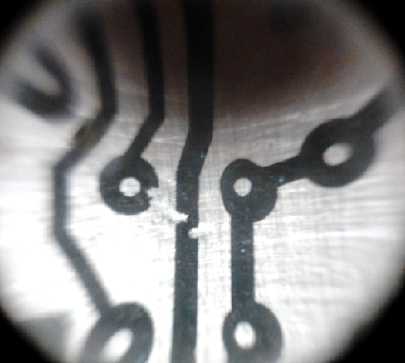
Meanwhile, on the afternoon of the 16th I tried printing
out the pattern for the bottom of the board as it then was on my other
laser printer. (The first printer prints fine "basketweave" patterns
instead of
black,
visible under a magnifying glass, which finally explained many of my
mediocre PCB making results, and why it worked better on glossy
magazine paper heated with an iron that usually smeared it just a bit,
than with the laminator and real toner transfer paper.)
Gaps in the printer's printing. They might be
unnoticeable
on paper, but they can make a mess of a circuit board.
 It
looked okay on paper, so I printed it
on the "toner transfer paper" and transferred it to a piece of circuit
board. It was abysmal. It looked bad, and moreover, some
areas didn't stick to the copper. They just floated off when the
backing was soaked and removed, even tho it had been run through the
laminator a
dozen times. I ran a drum cleaning cycle on the printer, positioned the
print in the middle of the page instead of on one side, and tried
again. It was much better, and I ran it through the laminator in a
different orientation on each pass. That seemed to work - there were no
loose toner
patches. But there were little missing bits all over, as if dust
particles were preventing adhesion. It was the printer. I took it apart
and tried to clean the drum and the fuser roller, but there was no
evidence of anything not clean and nothing helped. I left actually
making the board for another time, using somebody else's printer.
It
looked okay on paper, so I printed it
on the "toner transfer paper" and transferred it to a piece of circuit
board. It was abysmal. It looked bad, and moreover, some
areas didn't stick to the copper. They just floated off when the
backing was soaked and removed, even tho it had been run through the
laminator a
dozen times. I ran a drum cleaning cycle on the printer, positioned the
print in the middle of the page instead of on one side, and tried
again. It was much better, and I ran it through the laminator in a
different orientation on each pass. That seemed to work - there were no
loose toner
patches. But there were little missing bits all over, as if dust
particles were preventing adhesion. It was the printer. I took it apart
and tried to clean the drum and the fuser roller, but there was no
evidence of anything not clean and nothing helped. I left actually
making the board for another time, using somebody else's printer.
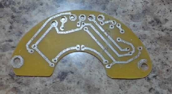 After I
finished the motor controller PCB design I started in on
the other one that would be needed: the magnet rotor position sensors
(optical since magnetic field transition points would be hard to
predict). I started with an old optical design of the desired 'drum'
slots form, from 2008 or 2009 before I discovered Hall sensors. That
made a good template to follow. I just adjusted dimensions, positions
and angles. I got the design onto a single sided PCB that just fit, and
the optical components just missed the moving parts, in
the cramped space inside the Electric Caik. I also noticed that if I
just trimmed a bit off one corner it could be fit through the center
hole and inserted or removed without disassembling the whole stator
compartment to get at it. With a couple of soldered-on nuts, or perhaps
captive standoffs, on the board, that should greatly simplify any
required repair. I finally made, populated and tested the optics board
the afternoon of the 24th.
After I
finished the motor controller PCB design I started in on
the other one that would be needed: the magnet rotor position sensors
(optical since magnetic field transition points would be hard to
predict). I started with an old optical design of the desired 'drum'
slots form, from 2008 or 2009 before I discovered Hall sensors. That
made a good template to follow. I just adjusted dimensions, positions
and angles. I got the design onto a single sided PCB that just fit, and
the optical components just missed the moving parts, in
the cramped space inside the Electric Caik. I also noticed that if I
just trimmed a bit off one corner it could be fit through the center
hole and inserted or removed without disassembling the whole stator
compartment to get at it. With a couple of soldered-on nuts, or perhaps
captive standoffs, on the board, that should greatly simplify any
required repair. I finally made, populated and tested the optics board
the afternoon of the 24th.
Now I have to wind coils for the new motor, and to make
and
populate the controller circuit board. Then paint, wire and assemble
the motor, and
build a case for the controller and wire it all up. Originally I hoped
to do it
all by the end of November - a tall order, as usual. But when printing
the board artwork, which had to be 'perfect', went badly, it made
delays. It turned out the printer at Microsec R & D, where Ed gets
very good circuit boards using the same process, was out of toner.
(The simple, single-sided optics board I made on the 22nd, and in spite
of making the traces rather wide, yes, I had to bridge a couple of
broken ones.)
I started thinking again about "remodeling" the original
Electric Caik Motor and doing the second one later. then I spent 2 days
on other projects, and it was clear that the motor wouldn't be running
this month.
On the 27th I went to order the 4000B logic NOR gates chip
in a SOIC package... and found it wasn't available, at least, not at
Digikey. It seemed to have been supplanted, probably long ago, by the
similar 4025B. I changed the circuit and board layout to that chip and
ordered some, along with a few other parts like some 2SC5101
transistors that seemed to be better ones for the LED lights. Amazing
how the simple act of ordering a few parts takes hours by the time
you've uncovered the various things you need from a list that must
contain hundreds of thousands of parts. If you don't have exact numbers
and exactly what you want down pat, I think buying in person is
actually faster... if you live fairly near a store and if it has what
you need.
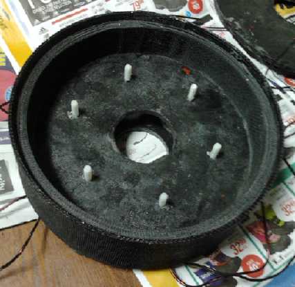 Caik Motor with nylon machine screws through
the coil centers.
Caik Motor with nylon machine screws through
the coil centers.
(These must be trimmed flush and can't have protruding nuts, since the
magnets spin right next to the dividing wall, centered on that radius.)
"Green" Electric Equipment Projects
Aquaponics
& LED Grow Lighting Project
 Plant bed earlier in the month
I meant to buy a pH meter
at an aquarium store. When I was there, I forgot to gt one. The pH test
strips kept saying the water was about pH 6. I had seen someone add
calcium
hydroxide (lime) and potassium hydroxide to his aquaponics system to
raise the pH in a youtube video. I was puzzled why the water might be
acidic, but didn't think too much of it. I added 1/2 teaspoon of
each. It seemed to make a slight difference.
The next morning (5th) I added a whole teaspoon of each.
Then the pH strip at last said it was 7. I came back in an hour and two
fish had jumped out of the tank, and were lying on the floor, dead! I
looked in the tank. One fish was in a corner at the surface, gasping,
and the other three were drifting around at the bottom and not upright.
I went outside and grabbed a pail of rainwater from a
bucket, and added some hot tap water so it wasn't icy cold, and put the
fish in it. I started pushing the listless fish around with a net to
get some water going through their gills. Two of them finally revived.
The third one's gills occasionally flapped feebly. I kept coming back
and pushing it around. It seemed to revive and soon lapse again when I
stopped helping it. Finally it too started swimming around, after an
hour or more.
Meanwhile, I had moved them to a plastic garbage 'can'. I
put rainwater on the stove in pots to boil, and I gradually added more
and more not-too-cold water. Then I took apart and drained
the whole system and refilled it with rainwater, using all there was
from three garbage 'cans'. It was just enough. (It rained overnight and
in the morning (6th) there was
more than ever.)
The fish seemed lively again. The one piece not
reconnected was the drain-down bed. I had added water until it drained
down, so there was only a little water in the bottom. I refitted it and
turned on the tap. Everything seemed to be running fine, but the fish
seemed to have become inactive again. Could it be that just that little
bit of the old water was harmful? I took out two small pails (7 L?) and
replaced them
with fresh rainwater.
I gradually realized that only the one fish seemed
entirely "normal". Two just
seemed to do almost nothing and maybe lethargically ate some food. (One
seemed to become a coward that fled for cover whenever I came near, if
it came out at all.) They gradually improved. The fourth one had
serious problems and never properly
recovered. I finally put it out of its misery. Never having eaten
tilapia
(that I know of) I cleaned and cooked it. It only made a small,
bony snack, but the taste seemed good.
These were the same broad range pH test papers I've been
using for batteries. It never occurred to me they might be wrong. The
colors were clearly those of "6" and then "7" pH, but really it was
probably at least 8 to kill the fish. (which also explains a few odd
results from my battery tests.) I finally tried a piece in plain tap
water: sure enough, it said "6"! And I've decided the guy in the
youtube video probably didn't know what he was doing... Maybe he was
using the same test strips. Later I got a pH indicator and it too
seemed to read acidic, including in tap water: 6.2. Could the
indicators all be right, and tap water around here is actually pH 6.2?
But if so, why would the fish die at just neutral pH, 7 or so?
In their stressed exertions, the fish had knocked the LED
light into the water. It was still on. But when I took it out, it
almost instantly quit working. When I looked at the circuit board, the
negative voltage traces were okay, but the positive ones were quite
corroded -- just like in a battery. I removed the floating plant unit
and I put an acrylic cover over the tank so they won't 'escape' again.
I decided to go with just the drain-down bed for plants.
On the 6th I started in on the LED grow-lights. Once again
I broke the old and not so transparent acrylic plastic diffuser face
off one of the unfinished flat panel lights and replaced it with the
'clear cracked ice' acrylic type. Then i
started checking out the blue and red LED emitters I bought a while
back. Specs for the red were .35 A, 2.5 to 2.7 volts - under a watt. I
don't like to run them at anything like maximum because they'll get hot
and won't last as long. I decided I wanted about 15 total watts. Since
these would be running during the day, the collectors should put out 13
to 14 volts. Call it 13 and 1.15 amps would be 15 watts - call it 1.2
amps
for 15.6 watts. If I placed 8 in parallel, it would be 150mA amps each
- under 1/2 of maximum rating, giving 'extra' light per watt. At .15
amps, I read 1.95 volts. That's a lot lower than most others. The blue
emitters were rated for twice the current, .7 A. If there were 5 in
parallel they'd be about 250mA each, or 6 would be 200. At 250mA a blue
emitter read 3.13 volts. (If it were critical I'd try more than one.)
Two blue sections plus two red sections would be:
1.95+3.13+1.95+3.13 = 10.16 volts. That should give full power at
maybe 11.5 volts up.
Another possibility would be three blue and a red:
3.13+3.13+1.95+3.13= 11.34 V. This should be full on at about 12.75
volts up and would give 'extra' photosynthesis - leaf growth - and less
flower production, as I understand it. I'm not at this point attempting
to make units with any sort of adjustable color balance. That would
take a big, not to say total, design change. Note also that at full
rated current the rated voltage would be about: 3.5+3.5+2.6+3.5 = 13.1
volts -- too high to consider putting four in the string for 12 volt
operation. It would have had to be: 3.5+2.6+3.5 = 9.6 volts. That would
be, eg, 1.4 amps with just 8 emitters instead of 1.2 amps with 23, and
substantially lower efficiency.
Last it occurred to me that 9 reds instead of 8 would have
5 that line up with the blues and four in between, as well as dropping
the design current to 133mA per red emitter. I didn't get any
farther for a while - I got more heavily into developing the unipolar
motor and the
Electric Weel generator.
BTW I read that two inventors recently won a Nobel prize
for inventing
high intensity blue LED emitters. In addition to getting 400 to 450nm
(nanometers) wavelengths for grow
lights (and other nearby blue wavelengths like 470nm), putting
phosphors over them makes white LED.s, which are so rapidly changing
the face of electric lighting. (The phosphors are similar to those used
in mercury vapor fluorescent lights, but the LED.s are minus the
ultra-bright mercury spectral wavelength spike that makes fluorescents
so unpleasant and bad for the eyes.)
Red (660nm, @ .15A): 1.95 V
Blue (450nm, @ .25A): 3.13 V
Making a 7" x 7" Flat Panel LED Grow Light
The clear "cracked ice" diffusers don't reduce
the light like translucent types,
but they break up the intense LED emitter light to more bearable
levels. For plant
growth lights and for space lighting mounted higher up on a ceiling,
they're great!
 The plants
kept growing... long and spindly from lack of
light. With this impetus, on the 26th I thought I'd finally throw
together the first red & blue grow light as a "morning project". It
went pretty smoothly until I came to the driver circuit board. There
was one I had made last summer and soldered most of the components
onto. I looked at it. It was terrible, made with the laser printer that
prints patterns instead of black... it had traces that were surely
broken. I decided I could bridge them, so I finished the board and
mounted it to the light. It was so bad I spent about an extra two hours
troubleshooting it before it finally worked. Even then it's the worst
board I've ever done, with about half a dozen wires bridging open
circuit runs, a diode on the back sticking up, and the whole board in
upside down and just hanging there because it just wouldn't solder and
hold to the copper bar. Not the least bit presentable! I'd have been
better off to unsolder the components, print and etch a whole new
circuit board, and redo it all. Ah, hindsight..!
The plants
kept growing... long and spindly from lack of
light. With this impetus, on the 26th I thought I'd finally throw
together the first red & blue grow light as a "morning project". It
went pretty smoothly until I came to the driver circuit board. There
was one I had made last summer and soldered most of the components
onto. I looked at it. It was terrible, made with the laser printer that
prints patterns instead of black... it had traces that were surely
broken. I decided I could bridge them, so I finished the board and
mounted it to the light. It was so bad I spent about an extra two hours
troubleshooting it before it finally worked. Even then it's the worst
board I've ever done, with about half a dozen wires bridging open
circuit runs, a diode on the back sticking up, and the whole board in
upside down and just hanging there because it just wouldn't solder and
hold to the copper bar. Not the least bit presentable! I'd have been
better off to unsolder the components, print and etch a whole new
circuit board, and redo it all. Ah, hindsight..!
Then I did some testing, and I made a CAT std 12V
extension cord to plug the light in with. I made a couple of small
changes to the board design, and threw out 3 other previously etched
boards that didn't look a lot better than the one I used. I definitely
need a better laser printer. Finally I made "mounting feet", that
hadn't been put on the case earlier. This was the second "morning
project" in a row that lasted all day. Later I was up until almost 2AM
at AliExpress.com ordering parts, some for LED lights. I got some PCB
mount push switches to turn the lights on and off. I re-read a
technical magazine article on LED plant lighting, and noticed the
410-450nm blue there was called "ultra-blue". Searching on "ultra blue"
found mostly "ultra violet" emitters. But now I found 415-420nm 3W LED
emitters (@ 56¢US), which I had missed before, by searching on
"violet" instead of "blue". That's closer to the center wavelength of
blue for plant lights than the 450nm ones. The next morning the browser
was still sitting at AliExpress. I thought to search on "LED emitter
violet -ultra". Having eliminated hundreds of "ultra violet" emitters
with the "-ultra" term, I found exactly one choice for suitable lower
cost (@ 72¢US) 1W violet 420-430nm emitters, right in the center
of the desired range of 410 to 450, and I ordered some of those, too.
Probably both wavelengths are better than 450nm. These are all a lot
more than the 10¢ white LED.s and, using 10 or more per light,
will have to be figured into my price for the grow lights.
I've found many times in the last few years that finding
something is half in finding the right place to buy it (eg, pottery
supply for many chemicals), and half in finding out the right name to
call it - or on the web, picking out the right search term(s)! (Q: "Do
you have hydrochloric acid?" Hardware store: "No!" ...wrong answer...
"How about 'muriatic acid'"? "Of course we do!" ...same thing.)
Tests: All 28 emitters shone brightly and
evenly. Currents, voltages: At 11 volts it drew 1.13 amps, at
12 volts 1.26 amps, and at 14 volts 1.33 amps. Voltage across the LED.s
was 10.0V, 1.9 for each red set and 3.1 for the blues, and only a few
tens of millivolts change with power from 11 to 14 volts. That seems
like quite good regulation. Below 11 volts, current and brightness
dropped rapidly. Power: 10.0V * 1.26A = 12.6 watts to the
actual emitters. The rest is consumed by the driver board to regulate
the current, eg, at 12 volts, 12 * 1.26 = 15.1W for an efficiency of
83%.
1.25 amps is .25 amps per blue emitter (rated for .7 max)
and .138 per red (rated .35 max). That's about where it should be. I
could add 2 more blues (6 per set instead of 5) to reduce them to .208A
while presumably upping the brightness just slightly. (lower current =
higher light output per watt.) One could almost add a third row
of
reds, but then it would start to dim with power supply voltage below 13.
The emitters have a small heatsink spot on the back. In
previous lights I positioned this on the copper heatsink bars. In this
light I placed them over the gap between bars to see how well the leads
carried off the heat. That makes easier assembly and saves a bit of
costly copper. I can feel that they get hotter than the bars, so I
won't repeat the experiment.
Conclusions: I very much like the new light. It's
very bright and pretty even. Vegetables will love it! It looks like a
smash hit to me!
My one small technical
concern is that they run rather warm. It's amazing how high temperature
will rise over a 7" x 7" area with just 15 watts of energy, and in
spite of the copper spreading the heat for air dispersion. Solutions
could be lower wattage, larger area lights, or heatsink fins above the
emitters and (especially) the pass transistor - which would make the
lights fatter. (At some point they're no longer "flat panel" lights.)
Or a fan.
I'll start in the next unit by extending the copper plate the pass
transistor is
soldered to. That's the hottest plate, especially when
the supply voltage is high (eg 14V).
If running a few lights for a while discloses no serious
problems, I'm probably about ready to produce flat panel grow lights as
well as space lighting. The thought of making some money from them is
appealing, assuming I can get to a reasonably short build time... or
get someone else to do much of the work. A nephew said he's too busy...
but he'd like to buy a room light and a grow light! The fact that they
run on 12 volts has also aroused interest from motor home owners. It
would seem there's probably a market - if the prices are low enough.
Well... I can contract out circuit boards, and perhaps the
component stuffing of them (evidently there's a good place in town with
automated equipment for it), and perhaps I could make a big steel punch
and die on the milling machine, and use it in an arbor press to stamp
out the shaped copper plates instead of doing each one by hand in a
number of steps. Then too, they'll be better and more easily done with
a little jig to hold the emitters in exact place while soldering them
onto the copper plates. The 12V CAT plugs, sockets, wall plates and
cords can be sold as adjuncts to the lights.
The next evening I was ordering other parts and looking
for transistors for the LED lights. Way back in BCIT in 1975 I remember
learning that a transistor typically has a 100mV Vce-sat. Thus I've
always assumed that a low dropping voltage power supply is simple -
that four (white) 2.9V LED emitters in series, totaling 11.6 volts,
could be run from a transistor controlled supply as low as 11.7 volts
without dimming. I paid the specs little attention, but apparently that
was just a generalization for small signal transistors. Now I've been
looking and seeing Vce-sat.s for higher power transistors like 1/2 a
volt to well over a volt - or even 3 or 4 volts. I also had neglected
the .6 or .7 volts loss through the current sense resistor.
This explains why my LED light power supply voltage has to
get up to about 13 volts instead of 12 to run the 11.6 volt white
emitter strings without dimming. I found and ordered some power
transistors (2SC5101) with a 'very low' .25 volt Vce-sat. These promise
four-string LED lights with full brightness at about half a volt lower,
12.5 volts. (with 11.6/12.5=93% linear power supply efficiency!) It
would be more convenient for running from a 12 volt supply if the
emitters were about 2.7 volts, but they aren't, and dropping series
strings from four emitters to three loses 25% of the light without
saving any power - four slightly dimmed are still brighter and
save a bit of power. And of course, if running on 12V batteries, it can
help save the batteries if the lights dim rapidly as the voltage gets
lower.
My mind started working on new power supply ideas (with an
opamp and the 2SC5101) that should give great regulation right down to
12.0 volts. But after giving it some thought, I realized the whole
thing is somewhat academic. Who really cares or notices if a light is
just slightly brighter or dimmer? The main thing is that the current
regulation circuit, instead of just a current resistor like I used with
my earlier LED lights, lets them work from 11 to 15 volts without
either being really dim at 12 or less, or else burning out at 13 or
more. And the plant growing lights have lower string voltages than
11.6V anyway - about 10 volts. They regulate fine down to 11 volts or
so. But I might
try a small modification: using a schottky (or a .9v zenor?) diode in
the base circuit to lower the sense resistor voltage from .7 volts to
.3 or .4. That should let it maintain full regulation (for the 11.6
volt white light strings) down to 12.1 or 12.2 volts supply - and over
95% supply efficiency at those voltages.
 On the 29th or
30th I put together a new LED light body the same shape as the others
but constructed a
little differently. Instead of using 1/4" acrylic or lexan for side
pieces and sawing a
groove for the edges of the copper sheets, I used 1/8" and glued in
1/8" thick strips with a groove space between them. I thought it might
be easier and look better. I don't
think it was easier, and because of non-uniform wetting of the strips
with methylene chloride, the sides looked splotchy. Scratch that idea!
On the 29th or
30th I put together a new LED light body the same shape as the others
but constructed a
little differently. Instead of using 1/4" acrylic or lexan for side
pieces and sawing a
groove for the edges of the copper sheets, I used 1/8" and glued in
1/8" thick strips with a groove space between them. I thought it might
be easier and look better. I don't
think it was easier, and because of non-uniform wetting of the strips
with methylene chloride, the sides looked splotchy. Scratch that idea!
In the same light I put a 1/8" sheet of clear lexan on the
bottom, then the "cracked ice" diffuser sheet on that. If I'm doing
lights for
boats, motorhomes and greenhouses, they're almost bound to get hit
occasionally on low ceilings or with gardening tools, and the thin
diffuser will easily crack. The lexan is pretty indestructible and
should give a reputation for durability.
Plant bed later in the month with grow light.
(The beans will soon hit the top of the 4' poles!)
Electricity Generation
Wind Power
After a calm summer and fall, the afternoon of the 6th
brought gusty November winds, the
waving treetops taunting me for not harvesting them while I pay rising
power bills. With the Coursera.org course on the subject and youtube
videos showing various and sundry VAWT windplant units, I thought of a
mounting that would be simpler than those I've been contemplating,
which
involved having the shaft go through the roof and putting the generator
in the attic.
It could have a 45° angled mounting base, perhaps 4' x
(4*sqroot of 2)', with brackets sticking over the peak of the roof to
bolt into the other face. This should be quite strong, and relatively
safe and easy to install on my tall, steep roof. The turbine part would
be above the roof line, but off to the side of it with the shaft
protruding down farther, with well spaced bearings. The lower part
would have a more horizontal roof, giving space to put the generator
connected to the bottom of the VAWT shaft by an efficient flat or
poly-V belt. This could be built on the ground and to an extent tested
there. Then it would be pulled up to the roof and fastened down with
lag bolts. (A commercial unit could have a larger and adjustable base.)
I can't help but think I could set up a CNC program to
make a top and a bottom piece (and maybe a middle) with curved slots
cut to insert or slide plastic rotor vanes into, holding their
curved airfoil shapes as desired. But again, don't I have more than
enough to do as it is? OTOH, the solar collectors are getting pretty
dismal as we get into overcast winter weather.
Without wanting to get too far or fast into it, I had a
lawnmower motor from an old and abandoned wavepower idea, and I
decided to dismount it, bring it into the house, and check it out. I
think it's a 24 volt DC battery operated
mower (there's no nameplate), and hence lower power and voltage than
the more typical(?) 120
VDC lawnmower motors for mowers with cords. I tried setting it on the
lathe, but I don't know the RPMs of the various lathe settings. I moved
it to the drill press. The shaft didn't seem totally straight and I
couldn't clamp it properly - it shook back and forth. So I just
finger-tightened the chuck over the threaded
end of the shaft and held the motor in my hand for each test. I got the
following results:
RPM
|
Volts O/C
|
Amps S/S
|
620
|
3.55
|
1.6
|
1100
|
6.2
|
4.6
|
1720
|
9.7
|
10.1
|
2340
|
13.4
|
10.5
|
3100
|
17.5
|
not done
|
The thin test clip leeds may have reduced the maximum
currents. (I figured the light drill press wouldn't start up on the
highest speed setting if the output was shorted, so I didn't try to
measure it.)
The Zahn DC to DC converter I'm using with the solar
panels starts working at about 18 volts input. Obviously to work with
that the
motor has to get up to about 3500 RPM in order to do much, and probably
closer to 4000 to really put out. It looks like it might put out 100
watts or so at around 2000-2500 RPM if a DC to DC voltage up-converter
is used.
The diameter of the savonius rotor/turbine and the wind
speed determine its RPM. What sort of RPM.s are expected? Let's say the
rotor is 1m diameter (.5m radius), and the cut-in wind speed is 4m/sec
(14.4 Km/Hr), which may perhaps be typical. Then let's say for a rough
guess that under load the rotor turns 75% of that speed, 3m/sec, at the
outer edges. (and of course more slowly towards the middle.)
The circumference is 2 pi times the radius or 3.14 meters.
3m/sec over 3.14m = .95 Rotations/sec
.95 * 60 = 57 RPM
To get 3500 RPM out of the generator, a speed increase of 61 to 1 would
be required. And say it put out 20 volts at 15 amps at the 4000 RPM,
that would be just 300 watts, with the RPM already maxed out (if not
more than maxed out). None of this seemed very satisfactory. A DC to DC
converter that uses lower voltages
and hence allows lower RPMs, but the power at lower RPM.s would still
be pretty low, probably under 100 watts.
At least it wouldn't need a very big savonius rotor to run it! I may be
somewhat underestimating the rotor RPM for the 1m diameter if it's
made with blades that have lift, and with an upstream "wind aimer", and
of course a narrower rotor
would spin faster - but would have less torque and power.
A 120 VDC lawnmower motor rated for 10 to 15 amps should
be
more suitable. All else being equal, it should put out the 20 volts at
something like 3500/5 or 700 RPM, a 'mere' twelvefold speed increase.
The flat belt pulleys could be (for example) 360mm and 30mm in diameter
for a single step increase. And if it put out half an amp at the MPPT
at that speed, that would be 100 watts, with lots of room on the up
side to go to 2000 RPM and perhaps a kilowatt of power with higher
voltages at higher wind speeds. I decided that's what I should look
for... a used 120 volt mower or a new 'replacement part' 120V mower
motor.
This is much the cheapest generator that I've uncovered if
you don't want to make your own. They generally have little or no
cogging, which is vital for wind power so that they'll start turning in
low winds. Note that the brushes have a little friction, and they'll
need occasional replacement, so it has to be accessible. (I should
remark that these mowers run off 120 VAC by virtue of having a diode
bridge inside, which converts the AC to unfiltered DC, which these
permanent magnet motors run happily off of.)
Besides mower motors, vehicle alternators might work well
if the powered field coil rotor (which uses power) is replaced
by one with permanent supermagnets. This also eliminates the brushes
and hence most of the friction. But one would again have to check out
RPM.s, output voltages and output powers for suitability. They might be
lower RPM with (eg) 4 or 6 strong supermagnet poles than with the
original 2 pole coil rotor. Then again, getting more voltage per RPM
might take rewiring the
coils. I don't intend to get into that study. (There's probably info on
the web for those interested.)
How much power is actually available in the wind? If the
VAWT rotor was conveniently 1m tall as well as 1m diameter, it would be
intercepting 1 square meter of wind. E = 1/2 m*V^2. The
weight of air at sea level is about 1.2 Kg/m^3, known as
"Rho". If the wind speed is 1m/sec, then 1 cubic meter of air goes by
in a second: 1.2 Kg of air. If it's 2m/sec, it's 2 cubic meters: 2.4 Kg
of air. And so on. This leads to the power being proportional to the
cube of the wind speed rather than the square, because more mass of
air is going through per time. The formula is:
P = 1/2 Rho AV^3.
At the cut-in speed of about 14.4 Km/Hr:
P = .5 * 1.2 Kg/cubic meter * 1 sq.m * 4 m/sec ^3 = 38.4
watts.
At 20 Km/Hr of course it's substantially more:
P = .5 * 1.2 * 1 * 5.56 m/sec cubed = 103 W
And at 30, 40 and 50 Km/Hr we get 347, 823 and 1608 W.
It can be seen
that high winds contribute energy to the
total annual production disproportionately to the amount of time such
winds
usually blow. However, only a fraction of the total energy of wind can
be
extracted. The graph shows the Betz limit as .58 of the
energy, and that a typical savonius
rotor gets .3 of it at best. Thinking of Erauw's savonius-darieus
hybrid, or one that he showed with six blades that I saw months ago,
and the idea of a front wind aimer, I suspect we can do somewhat
better.
In fact, as I think about the earlier unit with 6
blades... are they air scoops, or are they really airfoils - propeller
type blades? If one views them as blades, it should be possible to have
the RPM higher than the wind speed, and to attain somewhat more
performance. (This brings me
back to the self-aiming blades in order to have better airfoil shapes,
yet more effective around the circle than fixed blades with constantly
changing
angles.) The darieus type isn't supposed to start itself. But
does a darieus "H section" VAWT have to have only two blades? Can't it
have 3 or 4 more, so that one or more is always in a position to
provide some thrust, and hence be self starting? If it has many blades,
does it create its own spinning wind vortex to reduce drag? It seems I
have more questions about a myriad of possible designs than exact
answers. One factor in favor of making a wind turbine: whether it's
really optimum or not, almost anything works.
At some wind speed the output will pass the rated output
of the generator or the maximum safe RPM. Steps must be taken to slow
the rotor in such high winds, eg, by having the airflow aiming front
cover change its orientation to cover, at least partly, the "wrong"
side of the rotor. This in turn can be accomplished by having the rear
aiming vane at a vertically skewed angle where in sufficiently high
winds gravity is overcome to shift the vane's orientation, a technique
used in many smaller propeller type windplants.
Since the aim here is an example of a better model VAWT
for gusty winds,
and one simple
to produce, all the wind data and to some extent the calculations of
power and energy are much less relevant than for an economically viable
or commercial wind farm
site - whatever power it makes, it makes. Parametric measurements
however will be valuable in comparing one
model or design change against another. An anemometer and wind
direction indicator would seem to be the essential new measuring tools.
Wind Powered
Cart goes straight downwind faster than the wind!
Does it have VAWT EV Applications?
Going across to horizontal axis/propeller type
windplants... someone said there was a wind powered cart that could go
downwind faster than the wind by using a propeller - a windplant -
connected directly to the wheels. Intrigued and also wondering if it
might have any application to wind power I thought I'd check this out.
At first glance, the idea seems ludicrous, and apparently
many said so in internet discussions. On the other hand, a few of the
1%
that caught on got fed up with the many naysayers and started building
models that would move forward when placed on a treadmill with no wind
at all. Then
someone made a radio controlled model that did in fact travel downwind
faster than the wind. None of that, apparently, silenced the
detractors. Finally someone built a large manned cart, and the
performance of the Blackbird Land Yacht at about 3 times the
wind speed, going virtually straight downwind, was verified officially
by NALSA, the North American Land Sailing Association, in 2010. There
are videos of it on youtube.
Going straight upwind sounds easy enough: the faster the
cart moves, the faster the apparent wind, and as discussed above the
energy is proportional to the cube of the wind speed, so the more
energy there is to turn the propeller. So it would appear that the cart
could
easily exceed windspeed going upwind.
Going downwind, one quickly perceives that when the wind
speed is reached, the propeller should be becalmed - the wind can
provide no
energy to turn it. This is where everybody gets hung up.
The force vectors are conceptually tricky and I'm not entirely clear on
all of it myself, but here's one conceptual way a cart can move faster
than the wind: Imagine a
long lever that pivots on the left end, and the cart is attached to the
right end. Put a sail, say, in the middle, with the wind coming from
behind
the whole lineup. Since the left end is fixed, for the sail to blow
with the wind, the cart has to move twice the speed of the wind. The
attachment to the ground provides fulcrum for the wind's speed to be
multiplied.
Also, we know that windplant propeller blades rotate
faster
than the wind speed. Likewise, some vector calculations (I understand)
show that a landsailer with a 'propeller/wing' sail can tack on a broad
reach and go faster downwind than the wind speed. In the "land yacht"
the propeller is in essence
continually 'tacking', moving across the wind, as it turns.
The first trick is that the wheels are connected to the
propeller (by a bicycle chain drive), and the wheels are turning.
There's a
lever and fulcrum action between the ground, the wind and the cart
wheels. As the vehicle sits still, the propeller doesn't turn - its
speed is proportional to the vehicle speed, not the wind speed. The
next trick is that as it starts moving downwind, it's merely a
"windjammer", not using the airfoils of the propeller. And (as I
noticed on about the fourth watching of one of
the videos) the prop starts turning opposite to the expected direction,
thus in the direction it would turn if it was a powered airplane
propeller. This is obviously dependent on the gearing. If there was a
large gear reduction, the prop would turn the way the wind tries to
spin it, and the vehicle would start moving upwind. But as made, at low
speeds the propeller forces are smaller than the simple push from
behind. (It was said also that the propeller pitch is adjustable.)
As the wind speed is approached, the propeller is turning
fast enough that it's providing lift like an airplane propeller,
actually pushing air backwards to propel the cart forward. The
propeller drag - resistance to
turning - is low if the blade design is good. Since the cart itself has
little drag, the wind is moving at the cart's speed and hence causing
no air friction, and since the propeller speeds up as the cart does,
the cart continues to accelerate past the wind speed. This is what was
verified by the treadmill test models. Above the wind speed, the
apparent wind is coming from the front, and now the wind is trying to
speed up the rotation of the propeller instead of slow it down,
providing even more force to accelerate the cart. A key here is that
since the
actual wind is from behind, the wind forces slowing the cart down are
smaller than if there was no wind.
According to Wikipedia, all this could be done
electrically with a generator,
motor and computer instead of a mechanical linkage, too. By doing this,
we would
essentially put a wind plant on an electric vehicle roof. If the
propeller can be rotated into the apparent wind in any direction, by
electrical manipulation of forces we should have a wind powered
electric vehicle that can travel faster than the wind, regardless of
wind and vehicle direction. The part about potentially getting power to
go, eg, 30 MPH in a 15 MPH wind in any direction, even downwind,
was
less
than
intuitive
but
has
now
been demonstrated. If petroleum
becomes scarce or very expensive we may see many vehicles on the
streets that would be prohibited today. But a horizontal axis propeller
type vehicle would surely be rather dangerous for the streets. If it
was big enough to get much power, it might hit overhead lines, not to
mention obstacles to the sides of the vehicle.
A unit big enough to charge batteries could be a lot
smaller than one intended to provide full power to the vehicle. To
simplify the mechanics and keep the profile acceptably
low and narrow, a VAWT catching a rectangular cross section of wind
might be the simple solution - and might well be considered allowable
on streets if it had a screened outer casing so the spinning part was
enclosed. (This outer casing would also be used to aim the wind better
at the turbine blades.)
Then, in areas where strong winds aren't common enough
to warrant putting one on a car, one
might conceivably mount the VAWT on a trailer, towed behind the EV to
keep the batteries charged only on windy days. (I think I want to keep
my car roof clear for solar panels. But that's far more useful here in
summer than in winter, while wind power is the opposite.)
And potentially, if there were no other power available an
electric railway system could run with it on windy days, or just use
multiple windplants on the roofs of the cars to recharge batteries
including
while in motion. Railway grades are generally small so less torque is
needed for hill climbing than with a road vehicle (but depending of
course on the
weight being carried). One can conceive of a train powered by
windplants and solar panels on top of the cars, perhaps with a
driving motor/generator in each car. (Keeping to a schedule without
batteries
and external power might be problematic.)
Finally, one could put a windplant on a boat or ship -
again preferably an enclosed VAWT for safety - and use it to make
electric power for the electric propulsion system. (A sail-assisted
cargo ship made some years ago used less fuel and was more stable in
rough seas than common types.)
Here we see a potential fusion of wind power and electric
transportation technologies. Obviously it can be done. I won't say any
of these ideas are practical, but I won't rule them out, either -
especially for marine uses.
A Safe
Woodstove Thermoelectric Generator (TEG) with Peltier Modules?
On the 30th I was looking up some Peltier module info, and
I started thinking some more about making a TEG for woodstoves. The big
problem as I see it is that woodstoves occasionally get hot enough to
melt the solder and ruin the generator modules. Of course, they only
need to be ruined once to spoil the whole idea, so it doesn't help that
the output of the stove is within limits even 99.9% of the time. I keep
thinking that having water boil under high pressure at the highest
desired temperature, say 180°c, and having the steam circulate to a
radiator and return cooled, should solve the problem. But before I
started building it I started realizing that implementing such a system
isn't trivial. A huge hurdle as I saw it (once I had thought of it)
would be that the pressure
would make the liquid-filled heat transfer plates I'd bought for the
purpose bulge slightly, and then the modules wouldn't contact well
across their flat surfaces.
The electrical output with 100°c or lower TEG module
hot side temperature would be much lower, but it would be far easier to
create a working system using water, that can't be 'fried' when the
stove is hotter than usual.
If water was the means to transfer heat, or some of the
heat, from the stove to the modules, and if that water would escape
into the air if it boiled, then if the stove got too hot, the water
would boil off and the TEG would quit or work at reduced capacity until
it was refilled. That would make the modules perfectly safe. And
perhaps there could be a reserve tank, which would replace the escaping
steam with cool water as and if it boiled.
And this unit might perhaps be made with ordinary cheap
Chinese peltier modules, since they wouldn't get too hot. One could
afford twice as many at 1/3 the price to get more output, altho there'd
have to be a larger surface area to accommodate them.
Then I started trying things out with a meter, one ohm
resistor and a heatsink, and was getting a little over 1 watt on the
woodstove at 150°c from a real TEG module, and hardly 1/4 watt per
peltier module from a surface too hot to stay touching but not boiling.
(I couldn't find my thermocouple temperature probe.) I decided that
even if I could double or triple those figures with better setups, I'd
be better off doing a VAWT. Even doing more experiments with
magnet motors and lambda ray collectors might prove more fruitful.
But since I'm here, another potential means to protect
TEG.s good for up to about 200°c would be some sort of bimetallic
strip that would raise the hot plate off the stove surface if it got
too hot. While writing, I thought of a better 'bimetallic' design. It's
clamped to the stove and can't "migrate", so here's a quick diagram of
it.
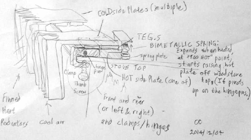
Electricity Storage
(Sorry, No Report on Turquoise Battery Project)
New Soldered Together NiMH EV
Batteries
The two "too-small" (size "frame 24") lead-acids for the
Mazda RX7 EV, which were always limiting the driving range, were
weakening and losing range after a year and a half, notwithstanding a
bit of sodium sulfate added to each cell when they were new. I used
them because two size "frame 27.s" wouldn't fit in their location.
New profile 12V, 50AH NiMH
"D" cell battery -
fatter but shorter with staggered rows of cells.
I decided
instead of trying to renew them, to make two 100AH 12V NiMH "D" cell
batteries, which I figured out could be fit in if they were done a
particular way. More exactly, they would be four side-ventilated 50AH
12V
batteries, doubled up. The way they'll fit is with the cells oriented
vertical and the boxes kept short, allowing a stack of four to fit in
12" height - fitting just under the hood. Except for the top battery,
the top cover is the bottom of the one above, saving three thicknesses
of covers. The terminals are placed on one side near the ends, making
the batteries no longer or taller. Then, the cells are staggered into a
hexagonal pattern that shrinks the length from 14" to 12". That makes
the width wider (over 9" with the terminal bolts) but there's plenty of
space in that direction. (Or I suppose they could be set on end, since
they're about 12" x 12" either way.)
At the same time, I want to
dismantle the two 90AH "D" cell tube batteries and make them the same
as these two new ones and another existing one: total five 100AH 12V
soldered batteries. That makes 8 more total 50AH batteries to solder
up. I ordered more "D" cells to make the last one from. That would
actually leave enough room under the hood for another battery - I could
finally fit twelve 100+ AH batteries... instead of having 11 including
two undersize "24"s. And looking ahead, I presume that I'll have the
Chevy Sprint running sometime not too far off, and I expect
then
to transfer all those NiMH batteries over to it.
Soldered packs are dangerous if they don't have
paper/cardboard wrapping the cells: the thin plastic covers can melt or
wear off, then the cell cases short circuit together and really start
heating up, destroying the pack... and at worst might potentially cause
injury or burn down the building they're in. "Cordless" power tool
batteries all have paper/cardboard wrapping around each cell. And yet,
companies will sell you individual cells with welded tabs intended for
soldering into packs -- with no paper wrapping. I made several
unprotected packs out of ignorance - and all of them I either took
apart again or they burned up. (3 burned IIRC.) Companies in the
battery business surely know better, so selling cells made that way
seems irresponsible. And I'd probably have "clued in" myself
if I'd seen "with tabs and cardboard wrapped, for making battery packs"
on the batteries for sale.
One new 100AH battery would get the RX7 EV on the road
again at least for short trips. I started the ball rolling on the night
of the 24th by cutting 150 tarpaper wrappings for the first 150 cells,
then wrapping the first 50 of them - one battery's worth. Right there I
ran out of "magic transparent" tape to hold the tarpaper wraps in
place, which was just as well as it was almost 1 AM. The next morning I
went at it again and made a vented wooden box to hold 50 D cells - one
battery. Then I made a little jig to cut all the wires to the same
length, cut and stripped them, and soldered up the 5 strings of 10
cells for the first 50AH 12V battery with #16 stranded wire. At noon I
stopped for breakfast. I had intended to get back to other things in
the afternoon, but having got that far, I wanted to finish it, even tho
I had to go out to buy terminal bolts to do so. I finished it about
supper time. This was longer than I'd expected to spend at it. (as
usual) But I was making good time except for having to stop and go
shopping. I don't think I can work much
faster.
The lithiums seem fine, but I think the NiMH batteries are
the best. That's really an opinion, not an objective appraisal. They're
around the same price. Only time will tell about the relative longevity
and robustness, which is doubtless the most important thing as long as
either type functions adequately. On paper the lithiums are good for
more cycles, even by 3000 to 1000 cycles. But how do they hold out in
actual use? The NiMH.s in
Toyota's hybrid cars (and their few RAV4 EV.s from the 1990.s that
escaped the crushers) have lasted a long time. Several EV size lithium
cells around Victoria have failed or behave oddly including one of my
eleven, and long life for laptop/netbook computer lithiums isn't the
universal experience.
But certainly, if each 100AH 12V NiMH battery
takes the better part of two full days to put together, and the dry
cells are costly, they're not going to become a popular
commercial product, so Chevron's blockade via acquired patents of large
(and cheaper) flooded NiMH cells will continue to keep the chemistry
out of the hands of most EV.ers.
On December 2nd, the batch of 50 more D cells I ordered
for another battery arrived. All-Battery.com is allowing USPS shipments
again, but despite the reduced shipping cost and a 12% discount from
the store, the 5.73 $US per cell came out to about 10$C by the time
they crossed the border and arrived here. Ouch!
Then there's the potential of NiNi and or NiMn to last
indefinitely. If only I had some time to work on them amongst all the
other projects, or could get some place that actually makes or wants to
make batteries to turn them from new chemistries into real, practical
batteries...
Real Lead-Acid - and NiMH - Capacities?
The 100amp-hour NiMH batteries each weigh almost 40
pounds, which doesn't seem like much less than the 'size 27' lead-acids
at around 45 to 55 pounds... but the density for 40 pounds works out to
66 watt-hours per kilogram, while lead-acids (per Wikipedia) are said
to be 33 to 42.
I'm smelling a rat that the 'size 27.s' can't actually be
the claimed 100+ amp-hours! At 42 WH/Kg, a 100AH 12V battery should
weigh 63 pounds - and at 33 WH/Kg, 80 pounds! The makers seem to be
seriously exaggerating their battery capacities, and also spec.ing them
at a very low 20 hour discharge rate. For example, the "Trojan" TM27 is
said to be 105 amp-hours. That works out to 105AH*12V=1260WH.
1260WH/23Kg=55WH/Kg... more than Wikipedia says it can be. At a more
generally useful 5 hour discharge rate, it's only rated for 79 amp
hours. Then, by weight, 79AH*12V/23Kg is 38 watt-hours/Kg. If we take
this lower capacity as the more realistic figure, then 50lbs/.79 would
be 63 pounds for 100 amp-hours. So the lead-acids really aren't 100
amp-hours.
And that's not the end either: At 75 amps, which might be
a reasonable average in many EV.s, the spec sheet says it'll run just
38 minutes. 38/60*75=47.5AH. The NiMH dry cells on the other hand, are
supposed to give close to full amp-hours at discharge rates as short as
1 hour, which would be 100 amps. At 75 amps, one expects over an hour
of running time.
There's theory. Then there's real. When everything is
working as well as usual and the 'CycleAnalyst' meter shows well under
20 amp-hours have been used on a trip, the voltage is dropping and
batteries of both types are likely to be pretty much used up, in
particular the 'size 24.s' and the 90AH NiMH.s in pipes. The individual
voltmeters show that the lower NiMH gets flat faster than than the
upper. Suspicion that not all the cells are contributing, that there's
some poor connection or maybe even more than one, is the main reason I
want to change them to soldered and up them to 100AH. And I'm not sure
my 'float charge' charging really brings them up to 100% charge,
either, owing to the relatively rapid self-discharge of NiMH and the
inadvisability of float charging dry cells at any higher voltage than
is really necessary. Again the suppressed large format NiMH alkaline
cells would make a difference (and would cost less).
I think the 100 amp-hour lithium ion batteries are
charging and holding charge better than either PbPb or (the 90AH)
NiMH.s. But one of them too appears to hold voltage under use a little
better than the other, and one of the 11 cells I bought won't charge to
the higher voltage of the others, so I left it out. That's a rather
pricey 9% reject rate, and someone else said one of his had exactly the
same symptoms. I need to specifically compare 100AH NiMH.s against the
100AH Li-ions so that I'm comparing apples with apples. This is another
reason for wanting more than one of them. (And a second CAT click-lock
socket on the one I have so it can be connected to a voltmeter without
unplugging its charger.)
http://www.TurquoiseEnergy.com
Victoria BC