Turquoise
Energy Ltd. News #83
December 2014 (posted January 4th)
Victoria BC
by Craig Carmichael
www.TurquoiseEnergy.com
= www.ElectricCaik.com
= www.ElectricHubcap.com
= www.ElectricWeel.com
Features: Home-done Dental "fillers"
(see "Month in Brief")
Month In Brief
(Project Summaries)
Seven Years(!) in Review
In Passing
(Miscellaneous topics, editorial comments & opinionated rants)
- Keep the Corrupt from Power
Electric Transport - Electric
Hubcap Motor Systems
* Unipolar BLDC Motor & Motor Controller Project
Other "Green"
Electric Equipment Projects
* CAT Standard 12VDC Connector products line extended:
- 4-plex receptacle faceplates
- cigarette lighter socket adapters.
* Aquaponics & LED Grow Lighting Project - Water pH, Aquarium.
Electricity Generation
(No reports)
Electricity Storage - Turquoise Battery
Project (NiMn, NiNi), etc.
* Battery-Supercapacitor Hybrid Car Starter Battery
* New Soldered "D" cells, 100AH 12V NiMH batteries for RX7 EV etc.
No Project Reports on: Turquoise
Battery Project (rats, no time!), Lambda
Ray Collector, Magnet motor,
evacuated tube heat radiators, CNC gardening/farming machine.
December in Brief
 I started the month
by getting the Mazda back on the road, by making a second 12V 50AH NiMH
battery on the 5th. I doubled it up with the other and installed the
100AH battery in the car on the 6th. I did the next one on the 8th, and
finally the 4th one on the 13th. After I installed them I checked the
lead-acid batteries in the back and found one of them had low voltage
and was probably ruined. So it was immediately back to 10 batteries
(128 volts) after all that work! Furthermore, the new battery from the
3rd and 4th 50AH units wasn't so hot. It held higher voltage under load
than the poorer of the two 90AH pipe batteries, until they both started
dropping to 10 volts at about the same time. I had made it from 10 new
cells and 90
that were 2 or 3 years old and subjected to varying uses and charging
or lack thereof. The lithiums also seem to be running more down toward
the
bottom of their allowable voltage range as well... aren't they supposed
to last thousands of cycles?
I started the month
by getting the Mazda back on the road, by making a second 12V 50AH NiMH
battery on the 5th. I doubled it up with the other and installed the
100AH battery in the car on the 6th. I did the next one on the 8th, and
finally the 4th one on the 13th. After I installed them I checked the
lead-acid batteries in the back and found one of them had low voltage
and was probably ruined. So it was immediately back to 10 batteries
(128 volts) after all that work! Furthermore, the new battery from the
3rd and 4th 50AH units wasn't so hot. It held higher voltage under load
than the poorer of the two 90AH pipe batteries, until they both started
dropping to 10 volts at about the same time. I had made it from 10 new
cells and 90
that were 2 or 3 years old and subjected to varying uses and charging
or lack thereof. The lithiums also seem to be running more down toward
the
bottom of their allowable voltage range as well... aren't they supposed
to last thousands of cycles?
To allow for 'non-new' performance, it would seem that the
batteries should optimally be 130 to 150 amp-hours or larger... like
the 8 volt golf cart batteries the original owner had selected for the
conversion.
It all reminded me why I'm trying to make batteries
that won't deteriorate over time and cycling, for which both the NiMn
and NiNi hold excellent promise. If only I could make batteries that
perform well and don't leak!
 In the second
week, I continued with the unipolar motor
controller. I did the circuit board on the 10th and had it populated
within a few days, and by the 19th I designed and 3D printed a
plastic end cover for the case. Then I cut a piece of aluminum to hold
the back end of the circuit board in place, since the board
was just a little too narrow to be held by the slots in the extruded
box. There
it sat until after Christmas. Then I improved the 3D printed end and
figured out pretty much how the energy recovery diodes and in-box
wiring would go.
In the second
week, I continued with the unipolar motor
controller. I did the circuit board on the 10th and had it populated
within a few days, and by the 19th I designed and 3D printed a
plastic end cover for the case. Then I cut a piece of aluminum to hold
the back end of the circuit board in place, since the board
was just a little too narrow to be held by the slots in the extruded
box. There
it sat until after Christmas. Then I improved the 3D printed end and
figured out pretty much how the energy recovery diodes and in-box
wiring would go.
Just before Christmas I got
sick - a nasty cold with
fever, which held on into January. Perhaps ironically, I sat at the
computer and did four little "health tips" write-ups on things I've
happened across, one of which I had been meaning to do for some time.
These are a little outside the scope of energy projects, but inasmuch
as I've happened across them in my travels, I think I should spread the
ideas around.
They were about improving or curing shortsightedness,
improving near vision while we age, home-done dental 'fillers' (a bit
soft to call 'fillings'), and preventing or maybe even reversing
thinning hair and baldness. After occasional bits of editing, I
uploaded them to my web site: http://www.saers.com/recorder/craig/
on the 30th, and refined the main page a bit.
The "home dental fillers" seem like an especially exciting
technique. It's simple and painless. Essentially, white ABS plastic is
softened into a blob with methylene chloride solvent, and is pressed
into the target (chip, groove, cavity?), to which cyanoacrylate glue
("Krazy Glue") has been applied. Pressing it in molds the ABS to fit
before the solvent evaporates and the plastic hardens again. If good
dental care (and the supplies and anesthetics usually used by dentists)
become hard to get for a while, it could even be a lifesaver.
 As I worked on
the 3D printed plastic end plate design for the motor controller, I
also did up two new CAT Standard 12 volt plugs & sockets ideas
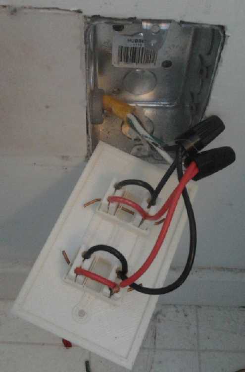
which I've had in mind for some time. One was a 4-plex receptacle plate
instead of a duplex plate. I already needed this to plug 3 LED lights
in for the aquaponics system. I figure one could make a cover
plate that would fit up to 9 sockets, eliminating most uses for 'power
bars'... but then they all have to be
wired.
As I worked on
the 3D printed plastic end plate design for the motor controller, I
also did up two new CAT Standard 12 volt plugs & sockets ideas
which I've had in mind for some time. One was a 4-plex receptacle plate
instead of a duplex plate. I already needed this to plug 3 LED lights
in for the aquaponics system. I figure one could make a cover
plate that would fit up to 9 sockets, eliminating most uses for 'power
bars'... but then they all have to be
wired.
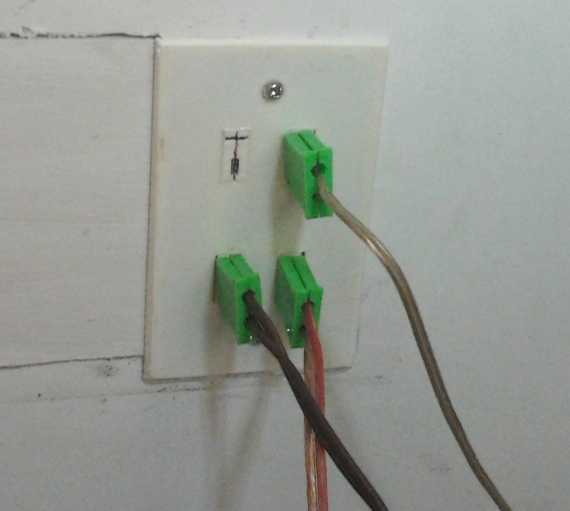
4-plex CAT socket plate holding 3 LED light
plugs.
(Now about that drywall filler, tape and paint...)
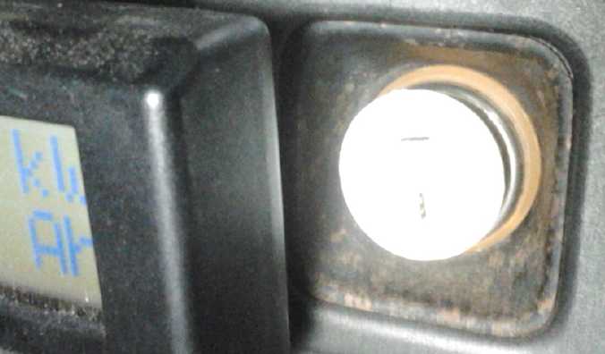
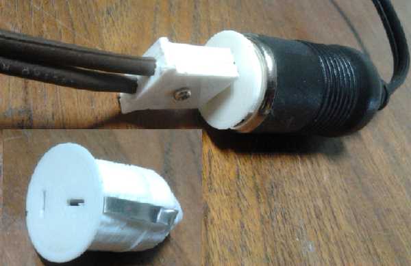
CAT Socket adapter in electric Mazda RX7 cigarette lighter socket.
 The other design was an adapter socket
that would put a CAT socket where a car cigarette lighter socket was.
The other design was an adapter socket
that would put a CAT socket where a car cigarette lighter socket was.
The point here is to provide a
migration path. 12 volt equipment makers can supply CAT plugs on their
equipment instead of ugly cigarette lighter type plugs. If the first
few products come with such adapters, soon enough everyone will have
them and it will no
longer be necessary to supply them - they'll be a dollar store type of
item.
I think one could actually fit two CAT sockets on the face, potentially
eliminating a 'splitter'. A click-lock socket might be another useful
idea... but I'm not sure how the whole adapter would lock into the
cigarette lighter.
At the end of the month I uploaded these designs (the
OpenSCAD files) to Thingiverse.com where there are now hundreds of
thousands of public domain 3D printer designs, along with the
click-lock plugs and sockets (belatedly) and the 12 volt NiMH D cell
battery case.
All great! But if I get nothing else done in January, I'd
like the unipolar motor and controller to be running. And maybe I'll
have some time to look into how lithium & fuel cells using
carbon/graphite are sealed, since it seems silly to have great new
battery chemistries but no practical batteries.
Seven Years in
Review
When I suddenly realized it was time for the annual "Years
in Review" column, I thought it could be kept to
a few paragraphs to briefly describe each project. But in seven years
I've ground away at or at least touched on so many interesting projects
that "brief
descriptions", even without hitting all the projects and sub-projects,
have become a considerable write-up. Of course I'd like to be able to
say that the early projects have been completed and wrapped up, but
instead they're either still in progress even after all this time (but
seemingly getting closer), or
they've evolved and moved into new phases of development beyond the
original plans - such as multiple sizes of Electric Hubcap type
motors, now made ultra-efficient with molded composite bodies, and soon
perhaps to be unipolar to use even less electricity and with simpler,
more robust motor controllers.
The first 'green energy' project, ocean wave power, which
I actually started in 2006, foundered on rocks of official
dysfunctionality combined with the hardware required being too big for
one person without waterfront property. That was just as well because I
later found and expanded on a
much better design, a sketch of which can be found in TE News #80. I
sense that it's the winner design for wave power the way the
three-blade propeller has been the winner for wind power. But it's
still too
big a project for me to champion if I'm to do anything else as well. By
2008 I had decided there were other 'green energy' things worth doing
too.
 Since 2008
I've created two battery chemistries that hold the promise of lasting
forever: nickel-nickel (~1.2 volts) and high voltage (~2.3v)
nickel-manganese. I'm the first person ever to get
manganese to hold its enticing high voltage metallic charge of about
-1.5 volts, using
lower alkalinity (pH < 14 with KCl salt) and the two trace additives
described in previous
issues. So far, no one has mentioned duplicating my results. However,
being "moderately alkaline" instead of pH 14 extreme alkaline,
the cells require carbon/graphite current collectors. The usual metal
used
as an alkaline cell current collector, nickel, will oxidize, and no
other metal works. (How
could one have nickel-nickel chemistry if the nickel won't oxidize?)
Since 2008
I've created two battery chemistries that hold the promise of lasting
forever: nickel-nickel (~1.2 volts) and high voltage (~2.3v)
nickel-manganese. I'm the first person ever to get
manganese to hold its enticing high voltage metallic charge of about
-1.5 volts, using
lower alkalinity (pH < 14 with KCl salt) and the two trace additives
described in previous
issues. So far, no one has mentioned duplicating my results. However,
being "moderately alkaline" instead of pH 14 extreme alkaline,
the cells require carbon/graphite current collectors. The usual metal
used
as an alkaline cell current collector, nickel, will oxidize, and no
other metal works. (How
could one have nickel-nickel chemistry if the nickel won't oxidize?)
But for all the chemistry, most of my cells don't perform
well and at no time have I
successfully made a cell that doesn't leak. The salty solution seeps
through the graphite at a surprising speed, and since any metal inside
the cell deteriorates rapidly, I can't use metal to make a leak-proof
connection. These are similar constraints to those of lithium cell and
fuel cell makers, but I'm at loose ends and don't know what to do next.
I don't know what to try besides things I've already tried.
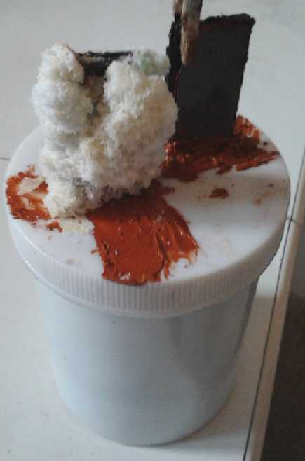
Salt crystal buildup on the positive terminal
notwithstanding
all attempts to seal the cell. Over a month or so all the liquid
in this cell made in October (which does have a lot of foam
filler and hence less liquid in it) was lost. And look at that salt-
corroded aligator clip!
Since 2008 also I have of course created a novel new
design of
excellent, highly efficient and lightweight powerful motors for
electric transport, with two
models implemented: the Electric Hubcap and the smaller Electric
Caik.
And this sort of motor is much more doable as home projects since they
don't
require custom die-cut laminates.
This fabulous success story would be more exciting if I had also
created motor controllers that could deliver those high powers without
going up in smoke, and mechanical devices that could
deliver this high power efficiently to vehicle wheels. So far in spite
of much experimentation, experimental development and intermittent
effort over the years neither
of these have been forthcoming. It may however be said they've come a
long way towards workable ideas and products. And in spite of much time
and effort -
again intermittently applied - the third model of the motor, the 28"
diameter Electric Weel motor that should have huge torque, isn't
finished yet. It's a bigger project than I thought. It makes the
smaller motors seem quick and simple to do. And even then the first one
is earmarked as a low RPM generator, which won't be testable as a
motor. Once I've made one I'll have the molds and jigs, and duplicating
it will be much simpler than making the first one... but not trivial.
At the same time applying the Electric Hubcap motor ideas to a
direct-drive bicycle or motorcycle motor with the magnets mounted on
the spokes of the wheel has had to be set aside again and again.
The main actual transport success has been the converted
Electric Caik Honda Outboard. It's quiet - nearly silent - and seems
reliable. The motor hardly gets warm with 1.5KW going in, suggesting
it's
good for at least 3 times as much power - perhaps 5KW, from a 15 pound
pancake motor, equivalent to 7.5KW for the 30 pound Electric Hubcap!
However, the
propeller is geared down in the foot (of most every outboard) so that
the motor RPM is maxed out without getting the boat up on a plane. So
it doesn't look very exciting and the motor's power limits
can't be
tested.
And if I got that much power going in, my motor controller would likely
blow anyway.
And then in spring 2013, I was offered the 'derelect'
electric Mazda RX7. Since this would actually work once it had
batteries, I thought it could give me some good electric car
experience. But it's been a project that's taken up quite a lot of time
in itself, without giving results beyond what anyone would get from
converting a car to electric except in experiments with mixed battery
types.
Last fall I bought a Kelly 36 volt, 400 amp BLDC motor
controller intending
to use it on the Sprint Car project, which was just about ready to try
out again, now outfitted with a variable torque converter transmission
with a large-drum centrifugal clutch. With enough amps, the motor will
move the car even without good performance from the torque converter.
But at just that same time, the concept of the unipolar
motor presented itself and I thought of applying it to the BLDC type of
motor. According to the design and records, and my implementation of
the controller, the unipolar motor returns magnetic field energy to the
battery via flyback diodes and an "isolation coil" as the motor coils
are switched off, hence apparently making much better use of the
electricity than
was previously thought possible. Not only was this aspect exciting, but
it appears the unipolar BLDC motor controller is much simpler than a
typical bipolar BLDC controller, with half as many power transistors
and no H-bridges - only low-side 'pull-down' transistors. This
also means only half as much heat is generated within the controller.
Since glitches in the H-bridges and heat are the primary cause of
failures of BLDC motor controllers, this means the controllers should
be much more reliable.
With all this going for it, I decided to put the
Sprint car on hold and make a unipolar Electric Caik motor and
controller, and try it out in the outboard. I thought maybe I could do
them in a month, but it's been
two now. There's been progress and the end is in sight, but neither the
controller nor the motor are finished yet. If it proves as good as its
promise, that bicycle motor might finally get done as unipolar.
Meanwhile the Sprint sits out its third winter with no motive power
under the hood.
I've stuck with all these electric transport projects for
all this time, but
of course more ideas come along from time to time that look too good to
ignore, and one sometimes needs to try a change from projects where
frustration has set in. I put up the solar panels and did some 12 volt
DC house wiring,
creating the CAT Standard 12 volt plugs, sockets, wall plates,
click-lock plugs and sockets, and now a "cigarette lighter" to CAT
socket adapter described herein. I uploaded the new designs to the 3D
printing site (Thingiverse.com) on New Years Eve, where they've already
aroused interest. On the 2nd I uploaded the click-lock plugs and
sockets which I hadn't previously got around to, and the 3D printable
10 D cell, 12 volt NiMH battery case (version 4).
I've made LED lighting, LED plant lighting, and a
thermoelectric refrigerator, all 12 volt units. It appears the fridge
is only marginally practical until improved COP peltier modules become
available. I delved into magnetic refrigeration for a while, then I
realized people do in fact seem to be working on improved peltier
modules, and that when (assuming) they become available, no one will be
interested in refrigeration units with moving parts.
Then there are promises of other means for generating
electricity. There's wind of course, and I occasionally do a bit of
work on the idea of a vertical axis wind turbine, as being a better
type for the gusty, variable direction winds encountered around my home.
But I'm more particularly thinking of
magnet motors, and people who seem to get energy out of thin air,
starting with Nicola Tesla a century ago. I haven't successfully made a
magnet motor, but it looks potentially doable. Certainly Muammar Yildiz
has demonstrated his widely. But surely it must be possible to do it
with far fewer magnets than he uses - over 1000! I feel the magnetic
forces are some large
scale extension of atomic thermal or nuclear forces and energy, and
that looked at at the nuclear scale it'll be recognized that they don't
violate any laws of thermodynamics or physics.
On looking into how energy might be "pulled out of thin
air", I checked out the electromagnetic spectrum. It appears the
spectrum was extended to 10,000 times the frequency and energy of gamma
rays by satellite observations in 2007, and of course to 1/10000 of the
wavelength. Little work seemed to have been done or excitement roused
outside the astronomical community, but visible light has an energy of
2 or 3 electron volts per photon, while such high frequency, short
wavelength rays would have somewhere around 1 to 100 trillion electron
volts per photon. In addition, the "X-ray observatory" satellites
showed that short wavelength rays, while concentrated in the plane of
the galaxy, come from all directions: "If you had gamma ray eyes, no
part of the sky would look dark."
These unnamed "very high energy gamma rays", surely, are
the source of the invisible energy that surrounds us in all directions.
They are much farther from gamma rays than ultra-violet is from
infra-red, so I felt they deserved their own name. I called them
"lambda rays". It seemed appropriate on several counts. (These and
other rays are not to be confused with "cosmic rays", which are not
electromagnetic "rays" at all but energetic charged particles
accelerated to near light speeds.) The devices that have claimed to
capture free energy vary widely if not wildly, but they all have
certain features in common. They all switch electromagnetic fields
rapidly on and off, using coils to generate voltages in the range of
hundreds of volts. They all have insignificant looking "collection
coils" wherein the lambda rays release "a whole stream of electrons and
anti-electrons" when they are coerced into reacting with ordinary
matter by the switched voltages and fields.
I've had very limited success with making a "lambda ray
collector" myself and I set it aside pending some new inspiration. But
just before Christmas someone phoned about NiMH battery packs, and said
he had been delving into this area with some success. I'm skeptical,
but some of the features sound right, so he just might have something.
He's in a nearby town with no car. When I feel up to it I'll drive out
there and have a look.
In Passing
(Miscellaneous topics, editorial comments & opinionated rants)
Keep the Corrupt from Power
"It's not that power corrupts, it's that power attracts corrupt
people." - Someone said it on youtube, I can't remember who. But
it seems right. Really moral, trustworthy people don't become corrupt
just because they land a powerful position. The corrupt will use
subterfuge and secret deals and pervert everything to gain and to hold
that same
position, until it becomes impossible for well intentioned, moral
people to gain it - or regain it. Open democracy and representative
government degenerate into a façade of lies, deception and
crimes.
"We're having a hard time winning the offices of power. But once we
have them the only way we'll give them up is when they cart out our
dead bodies." - Hermann Goering, before the Nazis attained power. (As
best I
recall it.)
Society must develop effective safeguards - conventions,
traditions and
means to prevent corrupt people from attaining positions of political
and economic power in
the first place, or we will continue the cycles of initial freedom,
prosperity and the rise of culture, followed by ever more overbearing
governments removing freedom after freedom until finally they steal
everyones' wealth, start a war or wars, and it all ends in a huge
collapse.
Again I commend the choice ranking vote. With a fair
voting system it becomes much harder for those with their own agenda to
control the agenda and prevent even relatively unknown but sincere
candidates from attaining the coveted offices when people recognize
"the usual" choices aren't doing any good and want to vote for real
change. I'm not saying it could
necessarily reverse the extremely corrupt, dysfunctional situations
that now
exist without a crash, but it would definitely have helped prevent them
from arising in
the first place.
 When it seems all is lost and there's no way
out...
When it seems all is lost and there's no way
out...
Sometimes there is!
Newsletters Index/Highlights: http://www.TurquoiseEnergy.com/news/index.html
Construction Manuals and information:
- Electric Hubcap Family Motors - Turquoise Motor Controllers
- Preliminary Ni-Mn, Ni-Ni Battery Making book
Products Catalog:
- Electric Hubcap 7.2 KW BLDC Pancake Motor Kit
- Electric
Caik 4.8 KW BLDC Pancake Motor Kit
- NiMH Handy Battery Sticks, 12v battery trays & Dry
Cells (cheapest NiMH
prices in Victoria BC)
- LED Light Fixtures
(Will accept BITCOIN digital currency)
...all at: http://www.TurquoiseEnergy.com/
(orders: e-mail craig@saers.com)
Daily
Log
(time accounting, mainly for CRA - SR & ED assessment purposes)
4th: Finished November newsletter/report (#82)
5th: Made 2nd 12V 50AH NiMH D cell soldered-together battery
6th: Installed the pair, 12V 100AH, in the Mazda, short test drive,
then left it to charge overnight.
7th:
8th: Made 3rd battery.
9th: 5.7 mile electric RX7 test drive... bought laser printer for doing
PCB.s and acrylic plastic for LED lights. Dismounted and tarpaper
wrapped 50 more cells for 4th EV battery.
10: Installed printer, printed unipolar motor controller PCB artwork on
toner transfer paper, laminated it to board, and etched the board
(bottom side, then top side). Drilled holes & started test-fitting
components. (Some layout adjustments will be required.)
13: Finished 4th 50AH 12V NiMH EV battery.
14: Assembled new batteries & installed in car. Removed another
bad lead-acid battery. Test drive; good.
15: Set up CNC and program and drilled bolt-hole template for Electric
Weel motor/generator. Started populating unipolar motor controller
board, soldering surface mount chips and inserting all smaller
components.
16: Soldered components to PC board. Test drive RX7 5.3 miles (to buy
prism to check LED emitter wavelengths.)
17: Soldered large components to board, cut copper bus bars for the 3
phase outputs. Started fitting board into extruded case & designing
end cover for the case. Corrected problem with CAT Standard 12VDC
4-plex outlet cover.
18: Finished motor controller box end cover plate design in OpenSCAD.
3D-printed test sample CAT 4-plex cover, then another one to use. (3D
printer was somehow out of square - so I adjusted it.) 3D-printed
Motor Controller box end plate. 3D-printed 9 CAT sockets for plate etc.
20: Wound main energy recapture coil for the unipolar motor controller.
Found a better light diffusing plastic for LED lighting.
22: Started Car Cigarette Lighter Socket to CAT Standard Socket Adapter
design for 3D printing.
23: Finished it. It worked fine on 2nd try, but still needs some
tweaking. (Now the CAT 12VDC connector product line includes sockets,
plugs, duplex & 4plex wall plates for regular 1110 electrical
boxes,
"deco" (rectangular hole) 1110 box wall plates, click-lock plugs and
sockets, and the cigarette lighter adapter.
24-31: sick.
27: Outfitted & attached bus bars in unipolar motor controller,
worked out energy recovery diodes wiring.
28: Revised end plate & 3D printed it. Also printed 4plex cover
plate with minor corrections.
30: Installed 4plex CAT receptacle plate on wall, for aquaponics
lighting.
31: Uploaded 4plex plate and cigarette lighter designs to
thingiverse.com for anyone to use. (A user commented favorably on the
previous CAT designs. Still to upload: click-lock plugs & sockets.)
Electric Hubcap Motor Systems - Electric Transport
Unipolar
('monopolar', 'homopolar') Motor
& Controller
Unipolar Motor Controller
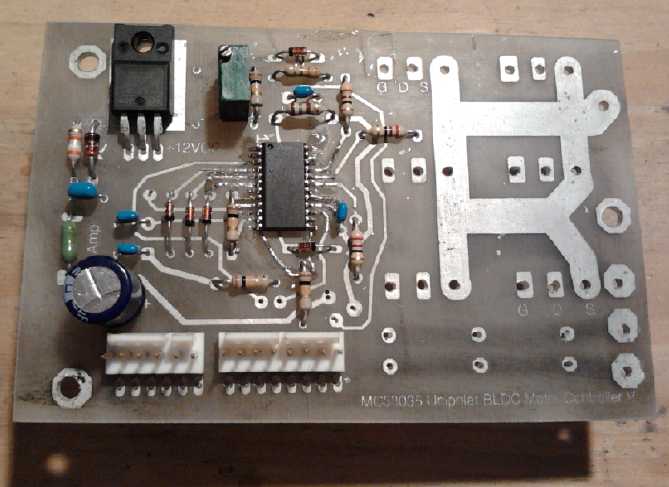
I bought a new laser
printer on the 8th, got it hooked up and running on the old i-Mac on
the 9th with the install CD, and printed the circuit artwork on toner
transfer paper on the
10th. (I thought it was pretty amazing something new actually installs
and works on it - most new programs and upgrades of older programs say
"Not Compatible" after installation and you're [hopefully] left with
the old version. Kudos to Samsung!)
I then did the bottom and then the top layers of the board
-
toner transfer and etching. I taped up the side not being etched with
packing tape, carefully applied. That seemed to work well.
For cleaning PC board copper, I'd been using the technique
from
"How to Electroplate a Penny": a toothbrush and toothpaste. However, I
couldn't seem to brush coffee stain off my front teeth, and I had
recently rubbed baking soda (NaHCO3) on them. That got rid of the
stain. It
seemed only
natural that it would clean the copper better too, and the results were
very good. Nylon scouring pads ("Scotchbrite" pads) still have their
place, but the toothbrush and baking soda did all but the most ugly
spots.
I had been using methylene chloride to clean the toner off
the finished PCB, but I tried acetone recently and it seemed just as
good. This time I tried simply scrubbing it with the toothbrush and
baking soda. That seemed just as good too, and with a pretty benign
chemical. (In fact, I've seen it touted recently (on youtube) as
an anti-cancer food or cancer treatment.)
 Then I drilled
holes in the board and test fitted some of
the larger components. There were
some non-obvious fitting problems with some of them. The most annoying
was that while there was clearance between the capacitors and the power
transistors, there would be nowhere to get an allen wrench past the
capacitors to screw the transistors to the conductor bars. I ended up
putting in one smaller capacitor.
Then I drilled
holes in the board and test fitted some of
the larger components. There were
some non-obvious fitting problems with some of them. The most annoying
was that while there was clearance between the capacitors and the power
transistors, there would be nowhere to get an allen wrench past the
capacitors to screw the transistors to the conductor bars. I ended up
putting in one smaller capacitor.
A problem that had been bothering me about those phase
power conduction bars (to the motor coils) suddenly seemed to solve
itself. On the outside of the case, the obvious thing to do to connect
the wire was to put a bolt through the wire lug and through the bar and
tighten it. But it would be hard for the installer to get a nut driver,
screwdriver or allen wrench through the front bars onto the back two
bars. (This is also a nuisance inside when connecting the
transistors.) I had thought of twisting the bars so the bolts would go
up-down or at least diagonally, but in addition to other problems, that
seemed to have considerable potential for shorting phases together if a
wire was loose or got shifted over.
The sudden realization was that if the back bars were
simply made longer than the front ones, their bolts could be beyond the
end of the one(s) in front. And then, since the rear bar can be
bolted from the rear, only the middle bar need be longer. Having the 3
bars protrude about .875", 1.5" and .875" would probably be about
right. (If the fat wires are in-line, they'll be in the way, but that's
solved by attaching the center one first.)
I have 5 nice aluminum extrusion piece "boxes" about 4" x
4",
6" long that I found at a scrap place, just about ideal for making into
cases for the first few units. If the circuit board is extended to 3.0"
wide, it'll fit into a slot inside, with room above for the board
components and room below for the off-board components - in particular
the large coil in-line with the power, that allows the batteries to
charge from transient reverse motor coil currents. And the plastic ends
of
the box including the end that the bars stick out through? I figured I
could make those to optimum "molded" shapes on the 3D printer.
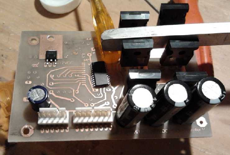
 On the night
of the 15th I soldered on the two SOIC
surface mount chips and inserted the component leeds of the other
smaller components. The next morning I soldered them on, and then
inspected the board with a magnifying glass (my eyes not being what
they used to be) looking for bad or missing solder joins (I found a
few), or broken traces owing to the toner transfer voids. As
I passed over the 14 pin NOR gate, I noticed it said "ALS86". Wait a
minute, didn't I use 4000 series CMOS? Then I realized it was the chip
for the previous IR2133 controller. It was an easy mistake to
make
when they look the same and the writing is too small to see. I blew a
heat gun straight on it while pushing on the end with a tool until the
solder melted on all 14 leeds and it moved away. That seems to be the
way to unsolder surface mount chips. I found the tube of
CA4025B.s and soldered one on. (It wasn't easy since the board now had
a lump of solder at each pin, so the chip leeds wanted to sit in the
valleys between, half way between pins. I got it straight enough to
work.) On the 17th I soldered on the power mosfets and large
capacitors, and found and cut a big piece of copper for bus bars.
On the night
of the 15th I soldered on the two SOIC
surface mount chips and inserted the component leeds of the other
smaller components. The next morning I soldered them on, and then
inspected the board with a magnifying glass (my eyes not being what
they used to be) looking for bad or missing solder joins (I found a
few), or broken traces owing to the toner transfer voids. As
I passed over the 14 pin NOR gate, I noticed it said "ALS86". Wait a
minute, didn't I use 4000 series CMOS? Then I realized it was the chip
for the previous IR2133 controller. It was an easy mistake to
make
when they look the same and the writing is too small to see. I blew a
heat gun straight on it while pushing on the end with a tool until the
solder melted on all 14 leeds and it moved away. That seems to be the
way to unsolder surface mount chips. I found the tube of
CA4025B.s and soldered one on. (It wasn't easy since the board now had
a lump of solder at each pin, so the chip leeds wanted to sit in the
valleys between, half way between pins. I got it straight enough to
work.) On the 17th I soldered on the power mosfets and large
capacitors, and found and cut a big piece of copper for bus bars.
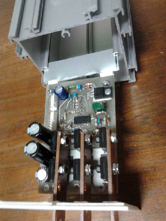
Then I started
trying to see how to fit everything into
the extruded aluminum case, and designed an end cover plate with slots
for the phase bus bars. The next day I 3D-printed a couple. They both
had problems, and, trying to get it to exactly fit the square
extrusion, for the first time ever I noticed the printer didn't quite
print
right angles - X and Y weren't quite perpendicular. (I also
printed the first 4-plex 12VDC CAT outlet covers and a set of 9 CAT
sockets.) On the 19th I modified the design, adjusted the printer, and
did another one. It was very close to fitting. I did a 4th one with
adjustments, and made it thicker. At last it looked like a keeper - and
"manufactured" like a molded plastic part.
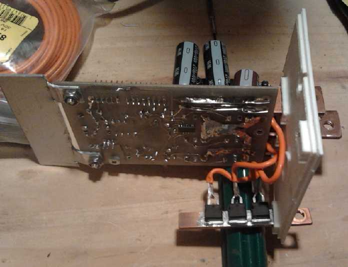
On the 27th I made the threaded holes in the bus bars for
the heavy wires, cut the middle one to length (the outer ones were
almost too short already), attached them to the transistors and
assembled it all. Then I checked some high current schottky diodes I
had to see how they'd work the energy recovery diodes. The case, which
could be soldered to a copper bus bar for heat sinking, was connected
to the cathode side. That was the wrong side to solder to the three
phase bus bars. But it was the right side to solder all three of them
to a single B+ battery voltage bus bar. Then the cable to the battery
would carry off the heat from all three, without adding more heat to
the phase transistors. Short wires would connect the phases to the
anode pins.
So this suggested a wiring layout, which clarified my
previously murky thoughts on just how everything might go together
within the case:
 * The battery
wire to the clamp at the end of a rather short
B+ bus bar sticking out of the case below the phase bus bars, with the
3 diodes soldered to it, and the energy recovery coil soldered to the
inside end.'
* The battery
wire to the clamp at the end of a rather short
B+ bus bar sticking out of the case below the phase bus bars, with the
3 diodes soldered to it, and the energy recovery coil soldered to the
inside end.'
* The other end of the coil is the main power to the circuit
board and to the motor coils "common".
On the B- ("ground") side, a short bus bar with a similar external bolt
connection would have the board ground wire and the current sense shunt
soldered (or clamped) to it. The other end of the current sense shunt
would supply the sources of the mosfets.
All the off-board components would be thus accommodated.
It was
a
pity I had made three round holes in the end plate to run heavy wires
through instead of slots for two bus bars. I can cut slots between the
holes... or 3D print yet another end plate. Since I hope to make 4 more
the same, I decided it was worth revising the end plate now instead of
later. I designed and printed the revised one the next evening (28th).
Then I realized I still didn't quite have it. There's "B+"
from the battery, then there's the "B+" to the motor coils, after the
in-line energy recapture coil. First I decided to change the design but
use this one for the first unit.
The copper bus bar I chose for the phases was 1/8" x 3/4",
which is the length of the heatsinks on the TO-247 MOSFETs. It's far
more than enough copper cross section. For the power connections, I had
a piece of 1/8" x 3/8" - about the equivalent of 2 or 3 gauge AWG.
That's still plenty, but when I put in the hole for a 1/4" bolt to
connect the wire to, there's not much left on each side. I don't want
to shrink the bolts, so I reluctantly concluded that 1/2" wide should
be the minimum for production. But maybe just 3/32" thick.
When I checked the fit, I decided the lower bus bars were
too near the edges of the case and might short to it, so I'll be making
the new
3-power-bus-bar version soon after all. And the bottom slot extrusion
in the
extruded box needs to be cut off in order to fit the energy recapture
coil - otherwise it's just a little too tall.
Electric Weel
Motor/Generator
On the 15th I finally got
back to this project and did the "lexan-ish" drill template for the
body screws. When I lined it up, it seemed the 96 outside holes were
just a bit close to the outside edge, but by only a slight amount.
Unfortunately the target rim edge isn't very wide, so the aim needs to
be good. Holes meeting the outside or inside edge of the rim wouldn't
be good. Part of the problem was that the units were slightly out of
round - a product of making them from eight separate pieces each, with
the adjoining edges sanded and then glued together. It would be hard to
get them absolutely perfect while dealing with gooey epoxy resin with a
very limited working time. (Maybe some sort of polyethylene
template/form?) So while they seemed about right where the body was
widest, they were definitely close to the outer edge where it was
narrowest. For the 24 stator inside edge and the 24 coil center holes
there's more room and the aim is less critical.
But I used the router with a 1/8" bit to drill the
template, and the holes were to be expanded to 9/64" with a drill. I
decided instead to expand the outer edge holes with a file and file
toward the inside, slightly moving their centers inward. Then I would
change the spreadsheet and the G-Code to move the outer holes inward by
about .04" for making the next template, should there ever be one. But
the holes seemed to be about 9/64" diameter already. Looking it over
again, I decided that it was probably about right after all.
I e-mailed the hydro power maker and said it was ready,
but he didn't reply. The last major item is the lexan rotor plate. This
is much lighter than steel, but it'll have a steel ring around the
outside to carry the magnetic fields. I'll have to tackle that some
time in January. It'll be good to see this project finally come
together!
"Green" Electric Equipment Projects
CAT Standard 12VDC Connector
Project: CAT products line
extended
 I had realized
that I would soon need more 12 V plug-ins
for lights around the aquaponics system. On the 17th and 18th, while 3D
printing the end for the motor controller box, I also made a CAT 4-plex
receptacle faceplate for standard 1110 electrical boxes. This was only
a modification of the duplex faceplate. It was considerably easier than
starting from scratch, but not trivial. A slightly off hole position on
the original became two mistakes on the new one. I remember having that
problem. It's best to fix designs as soon as the error is seen, before
it multiplies.
I had realized
that I would soon need more 12 V plug-ins
for lights around the aquaponics system. On the 17th and 18th, while 3D
printing the end for the motor controller box, I also made a CAT 4-plex
receptacle faceplate for standard 1110 electrical boxes. This was only
a modification of the duplex faceplate. It was considerably easier than
starting from scratch, but not trivial. A slightly off hole position on
the original became two mistakes on the new one. I remember having that
problem. It's best to fix designs as soon as the error is seen, before
it multiplies.
 I have since
near the beginning of the CAT
connectors project
in 2012 wanted a car cigarette lighter adapter. This
provides a path of migration from that rather ridiculous design that
was never intended to be used for general purpose plugs and sockets, to
the CAT system. On the 22nd and 23rd I designed and 3D printed one. It
worked fine on the 2nd try, but still needed some tweaking. I adjusted
the numbers in the design but didn't print another one.
I have since
near the beginning of the CAT
connectors project
in 2012 wanted a car cigarette lighter adapter. This
provides a path of migration from that rather ridiculous design that
was never intended to be used for general purpose plugs and sockets, to
the CAT system. On the 22nd and 23rd I designed and 3D printed one. It
worked fine on the 2nd try, but still needed some tweaking. I adjusted
the numbers in the design but didn't print another one.
'Cigarette lighter' adapter socket in electric
RX7.
(Now, if only the cigarette lighter socket
actually worked in either of my cars...)
Now the CAT 12VDC standard connector product line includes:
* regular sockets (for in-line or wall mounted connections)
* regular plugs
* Click-lock sockets (in-line or wall mounted)
* Click-lock plugs (hooded to reduce risk of short circuits, for
battery charger, etc.)
* duplex wall plates (2 CAT sockets [regular or click-lock]) for
regular 1110 electrical boxes
* 4plex (4 CAT sockets) 1110 box wall plates
* "deco" (rectangular hole) 1110 box wall plates
* Cigarette lighter adapter socket.
I already needed 3 of the 4-plex sockets for grow
lighting,
so it may not be long before I do a 6-plex cover plate. 9-plex - 3
sockets wide by 3 tall - is probably doable, and should pretty much
eliminate any need for power bars. Beyond that they'd probably get hard
to fit onto one faceplate and to wire into one box.
Another thing I might try is faceplates with sockets
'molded' into them, with a separate piece that screws to the back of
each socket front to hold it together once it's wired. This would
eliminate the cracks around each socket for a cleaner faceplate
appearance.
Aquaponics
& LED Grow Lighting Project
Water pH Problems
None of this is innovative or will come as any surprise to
an experienced aquarium owner...
On the 15th I tried out the pH test from a multi-parameter
aquarium test kit I bought. The gauge in the system still said it was
low, and the test kit now said it was around 5.5. That's definitely
acidic. Perhaps the tap water really is just 6... I'm now remembering
it does seem it's acidic on this island. (In fact pH even went below 5
at Bull Harbour near Port Hardy in the 1970.s when the Utah Mines
copper mine was causing acid rain all over the north end of Vancouver
Island. The water was always brown, acidic and dead and there wasn't an
earthworm to be found anywhere. Gardens wouldn't grow. Many or even
most people thought it was "natural" acid rain! Finally the mine closed
and it ended. But I digress.)
Reading the microscopic print in the booklet further under a good light
(they make it smaller every year!), it said - contrary to the
aquaponics info I've seen - that pH in an aquarium decreases over time,
owing to bacterial action. Photosynthesis should increase it, not
decrease it. Maybe it depends on the concentration of fish, and 6 fish
aren't enough to cause a lot of ammonia build-up and raise the pH.
The test kit also said not to raise the pH by more than
1/2 a unit
per day or the fish would be stressed. A web site also said a rapid
rise in pH could kill the fish. So it looks like what I did last month
that
caused the pH disaster was actually the right idea, and I went too fast
rather
than too far. Baking soda was the most recommended alkalizer. That
would certainly be more gentle and gradual than hydroxides... but don't
plants need potassium and calcium anyway? I decided to try a small
amount
of each, like 1/4 of a teaspoon of calcium one day and a teaspoon of
baking soda the next. Or maybe 1/8 and 1/2... once bitten twice shy.
After a few days I had to get somewhat more aggressive, because the pH
stayed acidic and refused to rise. I started using a teaspoon of baking
powder or 1/2 a teaspoon of lime each day. Then even more. The little
indicator continued to show a greenish color that apparently meant "pH
below 6". But I checked with the test strips and the test droplets and
they said more like 6.5. Finally on the 30th both agreed it was about
pH 7, and I stopped adding things for a while. So it looks like the
test papers are pretty much right on after all.
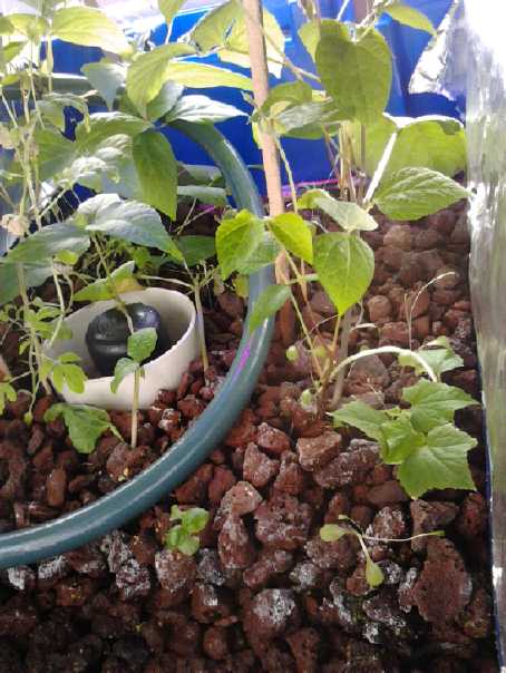
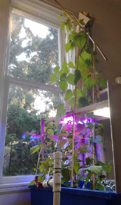 The beans were growing well and their poles had to be
extended. I should have done this mid-month, but I didn't get to it
until the 30th, by which time the tips were growing up and down looking
for a way up. Other plants are growing, but the pole/kidney beans are
definitely the star performers and their profuse foliage is now hogging
much of the light. Unless the lava rock has fertilizer properties,
they're way too big to be subsisting off anything but fresh nutrients
coming from the fish tank. A cucumber has small leaves with spots on
the corners,
probably indicating some deficiency. A pea plant is doing okay and a
tomato seems to be growing. And there's something that may be basil,
evidently a favorite for a quick aquaponics plant. It might also be
from a seedless mandarin orange seed I stuck in. I really wanted leaf
lettuce for sandwiches
and
burgers, but it doesn't look promising at the moment.
The beans were growing well and their poles had to be
extended. I should have done this mid-month, but I didn't get to it
until the 30th, by which time the tips were growing up and down looking
for a way up. Other plants are growing, but the pole/kidney beans are
definitely the star performers and their profuse foliage is now hogging
much of the light. Unless the lava rock has fertilizer properties,
they're way too big to be subsisting off anything but fresh nutrients
coming from the fish tank. A cucumber has small leaves with spots on
the corners,
probably indicating some deficiency. A pea plant is doing okay and a
tomato seems to be growing. And there's something that may be basil,
evidently a favorite for a quick aquaponics plant. It might also be
from a seedless mandarin orange seed I stuck in. I really wanted leaf
lettuce for sandwiches
and
burgers, but it doesn't look promising at the moment.
Below the LED lights the leaves are
'level-ish'. Above them,
the leaves all point toward the window.
A few other plants are trying to grow.
Aquarium
I finally got a ruler on the biggest tilapia. It had
definitely gained some meat. I was sure it was 9" long now and looking
potentially tasty, but in fact it was about 8" long. No doubt then I
was
overestimating the size of the tilapia when I bought them. Rather than
6"-8" they were maybe 5" to 7" - closer to the seller's estimate of 4".
But this one was near 9" by January.
He said that to breed them a male should be placed in with
3 or 4 females, in uncrowded conditions and warm water with gravel for
the male(s) to dig a nest(s) in.
I bought some aquarium gravel and put it in a shallow
plastic tray
which I placed in the tank - neat and tidy. The fish carried it all
around, almost emptying the tray, and seemed especially intent on
blocking the water exit pipe with it, raising the tank level
substantially and keeping the guck from flowing out into the sump tank.
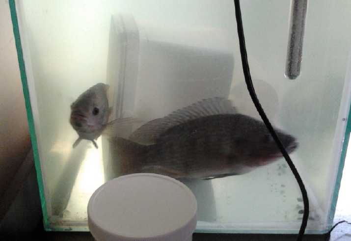 My biggest fish, now 8" long, was chasing and biting at
the other fish. In all the videos I've seen on tilapia breeding, an
aquarium was used. I finally broke down and got an aquarium, another
water heater and a filter/aerator. I put it in my electronics lab on a
previously surplus 'coffee table' size laminate top thing with drawers.
On
the 20th I filled it with rain water from a 200 litre barrel outside
and waited a day for the heater to warm the water up, then I put the
big fish in it. It's definitely easier to see in there. That's when I
got the ruler up close. It appeared to be a female. They have either
one (M) or two (F) holes near the anus, but they drop to the bottom
whenever you look at them, and it's not so easy to get a really good
view without netting the fish, stressing them and maybe getting jabbed
by a few dorsal spines. (The thing I noticed was that the poop seemed
to come out from a point 10mm behind where it seemed like it should.
That seemed to indicate an extra hole ahead of the anus.) A couple of
days later I put in the next biggest fish - a male, I believe. And then
some of the gravel. So far
nothing has happened.
My biggest fish, now 8" long, was chasing and biting at
the other fish. In all the videos I've seen on tilapia breeding, an
aquarium was used. I finally broke down and got an aquarium, another
water heater and a filter/aerator. I put it in my electronics lab on a
previously surplus 'coffee table' size laminate top thing with drawers.
On
the 20th I filled it with rain water from a 200 litre barrel outside
and waited a day for the heater to warm the water up, then I put the
big fish in it. It's definitely easier to see in there. That's when I
got the ruler up close. It appeared to be a female. They have either
one (M) or two (F) holes near the anus, but they drop to the bottom
whenever you look at them, and it's not so easy to get a really good
view without netting the fish, stressing them and maybe getting jabbed
by a few dorsal spines. (The thing I noticed was that the poop seemed
to come out from a point 10mm behind where it seemed like it should.
That seemed to indicate an extra hole ahead of the anus.) A couple of
days later I put in the next biggest fish - a male, I believe. And then
some of the gravel. So far
nothing has happened.
A pH test at the start of January showed 6.5. That seemed
pretty good. Some aquarium plants would be nice to have. Duckweed is so
simple. Too bad they eat duckweed!
Electricity Storage
(Sorry, No Report on Turquoise Battery Project)
Battery-Supercapacitor Hybrid Car Starter Battery
Someone phoned me with some questions about batteries. But
he also mentioned a video on youtube about a hybrid car starter battery
using a small 12 volt battery plus supercapacitors, or technically, a
supercapacitor composed of several low-voltage rated supercapacitors in
series. This idea is intriguing.
It seems that supercapacitors will put out tremendous
current and start a car (I've seen it in several youtube videos by
different people), but they don't hold a lot of charge. The 350 farad
size employed (divided by 6 in series = 58 farads) is only 58
amp-seconds of current or maybe 1/3 of a second of cranking before it's
down a volt. Since the car usually starts almost instantly, it works.
But if the car is left for a few days, it's likely to be dead since
most cars these days use a little current for clocks and computers even
when they're "turned off".
But any small battery will rapidly charge the capacitors,
which can then start the car. The video itself is a good advertisement
against using finicky lithium battery types. Nickel metal hydride would
seem to be the choice. How big should they be? Since it would only
take a few seconds to charge up the capacitors, probably even ten AAA
cells (one amp-hour or less) would work fine. Since there's no reason
to go so small, AA cells (two or more amp-hours) might be a good
choice. On the other hand, leaving the lights on might overpower their
current supply capacity as well as quickly drain them. D cells (8 to 10
amp-hours) can power the whole car except for starting it - and even
run the lights an hour or two if they're left on. I think that would
be my choice. C cells or two or three sets of AA cells might also power
the car, but would have much less reserve than the D cells. The D cells
could lose 1/2 their capacity - over thousands of charge-discharge
cycles and many years - and still work fine.
My next questions were about price and impedance. I went
to the Digikey website and at first it looked like the price would be
prohibitive, but soon I found more economical choices. I thought some
310 farad, 2.7 volt, 2.2 milliohm capacitors for about 15 $C looked
very good. The 2.7 volts appears typical. The only ones I saw rated for
higher voltages looked like they were composed of several low voltage
cells put into one
package. I was surprised to see supercapacitors have a "Lifespan"
rating, measured in hours - mostly 1000 or 1500 hours at 65°c.
Well, the one time they would probably get warm was when starting the
car. That would be short but intense heating. As with using NiMH dry
cells for car starting, I figure they'll probably last a long time, but
it's a question mark. None of the youtube videos so far seem to have
reported any failures. (BTW the 30 D cells NiMH starter battery in my
Toyota
Tercel has now been in it 4-1/2 years and still works great.)
The voltage drop when cranking depends on the "Equivalent
Series Resistance". In typical cranking (good lead-acid or 'enough'
NiMH batteries) the voltage may briefly dip down to around 9 or 10 or
even 8 volts. If the capacitors were at 13 volts and starting current
was 220 amps as the key was turned (small car), that would be .0022
ohms * 220 A = .484 volts, bringing it down just a bit to 12.5 volts.
This
gets the starter motor up to speed, and to a notably higher speed, in a
hurry. It's why supercapacitors start the car so fast, which is also a
key to their success since they can't crank very long. (What that
'extra' power does
to starter motor and starter mechanism life I don't care to speculate.)
Where the battery starts to recover up to 10 or 11 volts as it cranks,
the capacitors mostly just keep dropping. In the hybrid system with
batteries to charge them back up in a few seconds, at least a few tries
at starting should be possible.
The Video: www.youtube.com/watch?v=8miq6sDy0wA
New Soldered Together NiMH EV Batteries
Since I had 7 more soldered together, 50 NiMH D cells
batteries to make, I thought I'd do all I could to make them better and
faster.
On the morning of the 5th, I cut about 100 more tarpaper
covers for the cells. Since the tarpaper came off a roll, I noticed it
curled up
in one direction, and this time I cut them all to wrap that way. On a
few the tape had come loose
and the tarpaper unwrapped. Once in the battery that's not serious
since it has nowhere it can go. But this time I cut the 'invisible'
transparent tape I'm using longer than the paper. Once it's together, I
slide the battery out a little one way then the other and fold the tape
inside, for a better seal. None came loose.
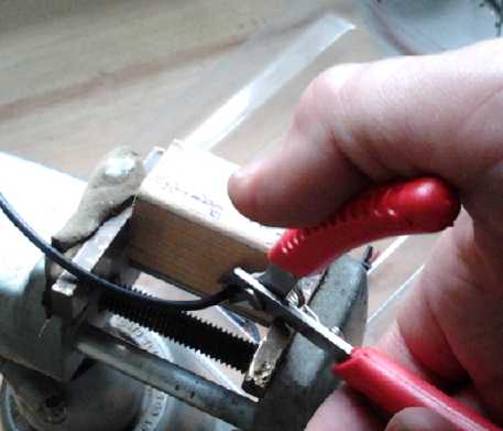 Then I
improved the little block of wood that I'm using to
cut the bridge wires to the same length with a "V" on the input side so
I didn't have to hit dead on to get the wire to slide into the hole.
Then I mounted it in a vise instead of holding it, and had both hands
free: one for the wire and the other for the cutters. I cut the 45
wires in just a few minutes once I had it set up. I pushed each wire
through the hole in the block of wood until it just showed coing out
the other side.
Then I
improved the little block of wood that I'm using to
cut the bridge wires to the same length with a "V" on the input side so
I didn't have to hit dead on to get the wire to slide into the hole.
Then I mounted it in a vise instead of holding it, and had both hands
free: one for the wire and the other for the cutters. I cut the 45
wires in just a few minutes once I had it set up. I pushed each wire
through the hole in the block of wood until it just showed coing out
the other side.
Stripping the wires didn't seem to get any easier. I tried
to put one in the vise but it pulled loose when I pried with the
strippers. I went back to holding it with pliers and pivoting the wire
strippers against those to strip the end off.
Next, since I'm using the final boxes to hold the cells
while soldering them, the box had to be assembled. And the terminal
posts had to be mounted with copper plates, each with 5 wires to
connect
the 5 sets of cells. I didn't time these fabrications. They took up the
afternoon.
In the evening I soldered the bridge wires to the cells.
When I turned them over and did the bottom sides, I put them in with
the honeycomb angles backward, and had cells instead of voids where the
terminal posts were. Choices were to move the terminal posts or to
rewire 20 bridge wires. Since I'm making 8 batteries that are supposed
to be identical and which are used in pairs, I chose the latter,
spending the extra time.
I finished it by soldering the terminal post wires to each
of the 5 sets of 10 cells to make it one 50 amp-hour, 12 volt unit. I
finished a little before midnight.
Get cells out of PETE wrapping plastic: 15'
cut tarpaper: 40'
wrap 50 cells: 40'
cut bridge wires: 15'
Make Box and terminal post assemblies: um, at least a couple of hours,
probably 3. 180'(?)
Strip both ends: 25'
Solder bridge wires: 60'
Resolder rong-angled bridge wires: 20'
Solder cells to terminal posts: 25'
Total: 7.0 hours
I only approximately timed things, but considering I spent
entire the day on this from maybe 9:30 AM to 11:40 PM, except for an
hour's music rehearsal and meals, I'm not sure how I come out with such
short "billable hours".
The next day I screwed the two batteries together and
installed them in the RX7. This didn't go smoothly and took about three
hours, with having to replace a cable that was too short from the
hard-to-access tube batteries in the big wooden box, cutting to shape
and inserting a piece of wood to ensure the battery didn't slide over
and the lower terminal posts short against a piece of the angle iron
battery mounting frame, and other little nuisances. Finally it was in
and I took a little test drive around the block. The battery started at
12.5 volts and was down to 12.2 afterward, having dropped under 11
going up a hill. I left it overnight to charge. The next day by noon,
it was just reaching 13.7 volts. I drove it 2.2 miles to a parking lot
with plug-ins near where I was playing in an orchestra concert and
plugged it in again. It held voltage better than either of the two 90AH
NiMH.s, one of which has also been stronger than the other, one typical
reading being 12.4, 12.2 and 11.8 volts, or, going uphill 12.1, 11.5
and 10.4 volts. I'll only know if one or even two of the tubes of the
lowest one aren't working right (as seems likely) when I take it apart.
The voltage does however spring back considerably once rested a while,
showing that more somewhat current than it can handle nicely is being
asked of it, rather than that it's being overdischarged.
The next day (8th) I spent a good part of the day on the
next one. I disassembled the six 3D-printed battery holders battery to
get the cells from it, and made two wooden boxes, so the next one
should take less time. I ran out of the "correctly curled" tarpaper
after 94 cells, and did the last 6 with ones curling the other way.
With folding the ends of the tape inside, they seemed fine. In the
evening the Hampton Orchestra had a wine & cheese party and I
played my supercorder with piano accompaniment. (I meant to record it,
but in the event it completely slipped my mind.) Then I soldered until
well after midnight and finished the battery.
On the 9th I did some driving - to buy a new laser printer
for PCB making and some acrylic plastic for LED lights. The weaker
90AH NiMH tube battery was getting down to the 10 volt limit during
acceleration on the return trip. I found I had driven 5.7 miles using
12.7AH (@ 128 nominal volts= 1625 watt-hours, /5.7 = 285 WH/mile) with
a short 1/2 hour recharge in a mall parking lot. That's not a long way,
but it's the longest for quite a while (and farther than I thought I'd
be going). Another new battery and bring the two 90AH.s up to 100 with
any required new cells, and things should be looking up!
In the evening I took apart the remaining 3D printed tray
batteries and two single tube batteries to get 50 more cells. At this
point, seeing I was using various used cells, I started testing them
and I
discarded a couple whose voltages were lower than the rest. I found a
couple of other cells to use. They were among a suspect bunch that had
been
badly overcharged, but these were holding voltage well. Ideally I'd
have charged them all, waited a couple of days to see how they were
holding voltage, and then load tested them to ferret out any weak ones
or any not holding charge well.
That would have been a prohibitive amount of work. I should have
checked the first 50 with the meter just in case, but 10 were new and
the other 40 were from the 60 cell battery. It hasn't been used a lot,
and I don't think I ever overdischarged or overcharged it. I wrapped
the chosen ones with tarpaper.
The fourth battery left me with just 40 remaining cells,
being used in the solar power system. ...and 5 more in my 6 volt
bedroom LED
lamp (the very first one I made) powered by a 10 watt solar panel. If I
took apart the two 90AH tube
batteries in the Mazda, they should be about enough to bring them up to
100AH and replace any weak cells. I might just have one 10AH tube
battery left. The solar power could use lead-acids for a while. At that
point the car would have five 100AH NiMH batteries, 4 lead-acid size
'frame 27',
and two 16 volt lithium-ions, all (supposedly) rated at 100AH or more.
If I'm lucky, the lead-acids will last until the Chevy Sprint is
running.
I finished the battery on the night of the 13th, and
installed the new 100AH pair the next day, when the weather was luckily
sunny. I neglected to unplug a plug from the other new 100AH NiMH to
the 7-voltages display. There was a small spark when a wire from the
loose socket touched the motor, and I had to replace one of the little
voltmeters and also one of the battery chargers. Yep, those are
'random' high voltages between batteries when they aren't all wired up
together.
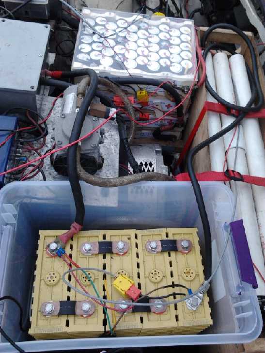
On checking the rear batteries after installing - only one
of which was being monitored on the dash - the first lead-acid I looked
at was only at 11.1 volts instead of nicely charged to 12.7v+. It was
one that hadn't been renewed, and it had a glued on top. This explained
why the voltages had seemed to drop so far so soon when I was driving!
I
had doubtless repeatedly overdischarged it pretty much into the ground
without realizing it. It shows the need to be able to see ALL the
battery voltages. I removed it and bridged the two neighboring
batteries. (The other three lead-acids were fine.) So despite all my
efforts building two new batteries, three were gone and there were
still just ten. After a year and a half and not one of the original or
I think even the second PbPb.s left in the car, I'm really starting to
hate
lead-acids, of which the car is down now to just three (all fine), plus
5 NiMH and 2 lithium-ion (@16v). I'd like to spring for another NiMH
for the 11th battery, but considering I still need to re-do the 90AH
tube ones to 100AH soldered, and the high cost, it'll have to be
another lead-acid.
On driving the car some, I discovered that the new 100 AH
battery didn't seem to be a lot better than the weaker 90 AH one. Of
course, except for 10 new cells, I had used batteries that had been
lying around for a couple of years or more, used for whatever and
subject to who-knew-what states and rates of charge and discharge.
The better NiMH batteries hold their voltage well, and the
others 'bounce back' once the load is off for a while. That means that
they still have good charge, but as they get lower their drive capacity
starts being overtaxed, the voltages dragged down by the heavy loads.
This has probably been the case for some time if not since the
beginning, but it wasn't readily apparent until I started monitoring
the individual battery voltages.
Lower currents would help. An 11th battery would drop the
currents by about 10%. And it appears that all the drooping voltages
would hold much better if the batteries were just somewhat bigger, like
maybe 130 to 150 amp-hours or so instead of 100. Thus the plan of the
original converter of the car was evidently quite sound: He used
eighteen 8-volt golf cart batteries which (looking at a Trojan
brochure) are available in 150, 170 & 190 AH capacities (20 hour
rate), or 125, 145 & 155 amp-hours at a 5 hour rate, weighing 56,
63 & 69 pounds each. These would seem to be the optimum sort of
size, and smaller and lighter than the more common twentyfour 6-volt
golf cart battery configuration.
This
rather disappointing result brings me right back to one of the main
points for trying to make a new battery chemistry: of very much wanting
everlasting batteries that don't deteriorate. I now have the
chemistries - two of them that should work great - nickel-nickel and
nickel manganese. What I haven't been able to do is make practical
cells that
perform well and don't discharge from air leaks and ooze their
electrolyte out the terminal posts.
In the meantime: I could obviously fit one 8V golf cart
battery in (they're shorter) instead of another 12 volt. I wonder if I
could squeeze two in and have 16 volts, total 144? Otherwise, when the
next 12 volt one gets weak, I could fit 24 volts with three 8 volters
where two 12 volters were.
But this all seems so unsatisfactory! I must finish the
unipolar motor and controller and try them out, then finish the Sprint
'ultra-efficient' EV conversion that will hopefully use less current
and even less power in the first place. Then the range should rise
substantially and the import of all these battery issues will shrink to
much smaller proportions.
http://www.TurquoiseEnergy.com
Victoria BC Canada