Turquoise
Energy Ltd. News #84
January 2015 (posted February 5th)
Victoria BC
by Craig Carmichael
www.TurquoiseEnergy.com
= www.ElectricCaik.com
= www.ElectricHubcap.com
= www.ElectricWeel.com
Month In Brief
(Project Summaries)
- Mazda battery 'upgrade' - 'New' EV? - Rick's energy
projects - Unipolar motor (& controller) construction - Aquaponics
& next LED grow light
In Passing
(Miscellaneous topics, editorial comments & opinionated rants)
- Energy Invention Suppression Cases Cataloged in 2008
- Patent System: Far More Disgraceful than I Ever Dreamed!
- Woodrow Wilson apparently soon regretted creating the US
"Federal Reserve"
- Financials
Electric Transport - Electric
Hubcap Motor Systems
* Unipolar BLDC Motor & Motor Controller Project
* Vehicle Transmission Thoughts and Ideas: RWD vs FWD, gear + belt
* Mazda RX7 NiMH "Battery Upgrade"
Other "Green"
Electric Equipment Projects
* Aquaponics - beans, tilapia, hatched tilapia
* Next LED grow light
Electricity Generation
* Some scattered thoughts on Lambda Ray 'collectors'
Electricity Storage - Turquoise Battery
Project (NiMn, NiNi), etc.
* A Lead-Acid Battery renewal success story
* New NiMH Battery Pack Blow-up: Cordless Power Drill Battery
* Lithium-Iron phosphate versus Nickel-Metal hydride Battery Life -
report from a LiFePO3 battery user
No Project Reports on: Electric
Weel motor, Variable Torque Converter Transmission, Turquoise
Battery Project, Magnet motor,
evacuated tube heat radiators, CNC gardening/farming machine.
January in Brief
The amount of money I've been eking out an existence and doing R &
D on is now
almost a year late and has been cut almost in half. Last summer I
mortgaged my house, and at Christmas my Mom bailed me out of credit
card debt. (Thanks Mom!) I spent notable time in January trying to
re-organize
and rearrange my finances. (And it's delayed this newsletter a day in
February.) I'm not sure I can continue devoting so much
of my time to sustainable energy projects for 2015 and beyond. I've
written more about this in "In Passing", My Financial Gripes.
 Early in the
month I figured out that I could very easily add a couple of
the four "quintos" dry cell pipes to bring the two 90AH pipe batteries
in the
Mazda RX7 up to 100AH, and did so. (The hood just closes.) However, the
improvement was slight.
The weakest battery hardly seems any better. Driving in about the least
hilly direction, I went 5.8 miles shopping around on a warmish day and
could have gone somewhat farther, but voltages were dropping to the 10
volt "best not go under" limit by the last hill up getting home. It
really needs that 11th battery, of any type, to reduce the currents a
little more. I ordered a 'reconditioned' lead-acid on February 2nd.
(Got it on the 4th.) I
also ordered another 100 NiMH D cells to put together later via the
insidious marvels of credit cards.
Early in the
month I figured out that I could very easily add a couple of
the four "quintos" dry cell pipes to bring the two 90AH pipe batteries
in the
Mazda RX7 up to 100AH, and did so. (The hood just closes.) However, the
improvement was slight.
The weakest battery hardly seems any better. Driving in about the least
hilly direction, I went 5.8 miles shopping around on a warmish day and
could have gone somewhat farther, but voltages were dropping to the 10
volt "best not go under" limit by the last hill up getting home. It
really needs that 11th battery, of any type, to reduce the currents a
little more. I ordered a 'reconditioned' lead-acid on February 2nd.
(Got it on the 4th.) I
also ordered another 100 NiMH D cells to put together later via the
insidious marvels of credit cards.
But after nearly two years
of 'sort of' having an electric
car, I finally got tired of the Mazda RX7 with its short driving range.
It really seems to need bigger batteries in order to work well over
distance, like 150AH instead of 100AH, because the smaller sizes (in
all chemistries) seem to have not only less energy storage, but also
somewhat marginal current handling capacity for the job asked of them.
(In spite of the lighter vehicle weight with NiMH.s, lithiums and less
overall installed battery
capacity.) I thought of the several new EV.s like the iMiev and Leaf
and their 100Km+ ranges, and of the prize of much extended range from
an ultra-efficient conversion, hopefully further improved with a
unipolar Electric
Hubcap motor. Surely I could at least be running something better than
what I have seems to give me. I test drove a used Leaf at a Nissan
dealer. (It was one of several there and there are also some at
motorizevictoria.ca in Sydney BC -- USA car rental cars sold into
Canada after the rental companies don't want them anymore) It was
lovely and at 22000-25000$ they are much less than new,
still they cost much more than I
can afford.
Then I enquired around the VEVA EV club circles, and found
that someone locally had a Ford Escort wagon EV, that had been
converted professionally when new in 1992. It used only 18 - 6 volt
golf cart batteries (108 volts) instead of the usual 24, and supposedly
had a 100Km range. (With new batteries, of course.) He wasn't driving
it because it needed new batteries - and a new charging system. The
range spec is probably overly optimistic, only for brand new batteries
on level ground, which we have very little of in BC. (The owner had to
stop and
charge overnight twice to get it from North Vancouver where he bought
it to
Victoria, which should theoretically have been doable.) But even
trimmed back some it
still indicates the top sort of range of most EV.s with lead-acid
batteries - and yet with only 3/4 as many
of
them. (In fact, it's about the same battery capacity as the Mazda's
original design, but
with 18 regular 6 volt golf cart batteries instead of 18 'special' 8
volters - 108 volts instead of 144 but at commensurately higher current
capacity.) It looked
nice and it was in good condition for its age, for ~1/5 of the
price of a Leaf. That was more my style! (Unfortunately I neglected to
get a picture of it.) With some NiMH.s and lithiums making it lighter
it might just get that 100Km range. With a new wagon that would
get to Sooke
or Duncan and back, surely I could sell the gas powered Tercel wagon
since I
do so little long distance travel any more.
 Then the
person who found the contact info for the Escort
owner showed me his 'new' 1998 Suzuki Swift. (same car as
my Sprint but manual transmission, 2
door.) It was a beautiful looking car with like-new
green metallic paint and no apparent rust. The previous owner had
bought it and all
the parts to convert it to electric in 2009, and had put in the motor
with clutch adapter plate (and for some reason electric window winders
and
door locks), and then got sidetracked and never finished the project.
The new owner had bought it only to take the uninstalled parts and use
them in a conversion of a Volkswagon Beetle he had already started. He
plans to sell the Swift again. So there was a Swift complete with
electric motor for just 1500$, but needing the other parts for a
conversion. Let's
see... I could take the required parts from the Mazda and install them
in the Swift, sell the 50HP motor and transmission adapter from the
Mazda, and have the RX-7 hulk towed away, of course keeping all its
fine batteries, the LED lights, and anything else that seemed useful.
Then the
person who found the contact info for the Escort
owner showed me his 'new' 1998 Suzuki Swift. (same car as
my Sprint but manual transmission, 2
door.) It was a beautiful looking car with like-new
green metallic paint and no apparent rust. The previous owner had
bought it and all
the parts to convert it to electric in 2009, and had put in the motor
with clutch adapter plate (and for some reason electric window winders
and
door locks), and then got sidetracked and never finished the project.
The new owner had bought it only to take the uninstalled parts and use
them in a conversion of a Volkswagon Beetle he had already started. He
plans to sell the Swift again. So there was a Swift complete with
electric motor for just 1500$, but needing the other parts for a
conversion. Let's
see... I could take the required parts from the Mazda and install them
in the Swift, sell the 50HP motor and transmission adapter from the
Mazda, and have the RX-7 hulk towed away, of course keeping all its
fine batteries, the LED lights, and anything else that seemed useful.
I eventually suggested to the Escort owner all he had to
do
to have a useful car was get nine 12 volt battery chargers, hook them
up with a power bar, license the car (he didn't have any other) and use
it around town. Even if it wouldn't go half of 100Km, it should still
be quite useful in Victoria. For some reason all the batteries in the
front had lower voltage than those in the back. With separate chargers
they can be replaced two (6v+6v) at a time if some are still good while
others are failing.
Even bringing the batteries over, switching from the Mazda
to some other car would somewhat
interrupt the continuity of the battery longevity tests, but it would
contrast one conversion against another -- and driving something with
longer range would be much more practical. But the main problem is that
doing the Swift would be another project, and a side track. I was
looking for an EV for now until whenever (and surely!) I at last
succeed with the
ultra-efficient conversion of the Sprint that I already have. Not!,
yet
another
project!
Anyway there's no rush and another possibility is in the
air. I'll take my time. I
still drive the Mazda to nearby destinations.
On the 26th I went to visit Rick, a retired plumber I used to
work with
in School District #61, who lives rurally in Metchosin BC. He has done
a
number of interesting energy projects:
* an electric S10 pickup truck conversion
* 500 watts of solar PV panels hooked to batteries (PbPb) and an
inverter
* two very nice rocket stoves
* a 3-blade
windplant on a tall tower, which pivots to raise and lower it with a
winch
* solar hot water - also tied into a rocket stove for our cloudy winters
* and an
enclosed fireplace hooked into his furnace ducts.
(I should have taken some pictures!)
They all work well except the windplant, and that's only
because he's on the side of a ridge and the whole property is in a bad
wind shadow. He also says the rocket stoves have much more of a
"babysitting factor" than regular airtight woodstoves, having to be fed
small amounts of wood every hour or so. He does nice welding. I drool
over his large, relatively clean workshop space! (Of course, if I had
it it probably would gradually accumulate a mess.)
Now he's planning a gassifier to run cars off firewood. These were in
fact very popular in Europe in world war two when gasoline wasn't
available.
 As the
unipolar motor
controller was getting towards finished, I decided I'd also better
get on with the motor construction. Over the days I wound the coils and
coated them with ilmenite (nanocrystaline 'magnetic powder' suspended
in "plasti-dip"),
tested the optics board, painted the motor body (polyurethane 'skin'),
wired in the coils, fitted the optics board, and finally bolted the
stator side together. Then I cut an 8" long shaft and milled keyways in
it. In the last days of the month I assembled it, but discovered I had
drilled some body holes too large. The bolts were supposed to thread in
but they slipped though. Except for that, it's built. I'll put strips
of polypropylene cloth over the ends of some waxed metal threaded rods
(shown), paint them with epoxy (also put some in the holes), and stuff
them in. The PP-epoxy should bond perfectly to the PP-epoxy of the
motor, but with the wax the bolts (rods) shouldn't stick. When it sets
I'll unscrew them, put on the 'lid' or 'end bell' (as shown), and screw
in the nylon ones.
As the
unipolar motor
controller was getting towards finished, I decided I'd also better
get on with the motor construction. Over the days I wound the coils and
coated them with ilmenite (nanocrystaline 'magnetic powder' suspended
in "plasti-dip"),
tested the optics board, painted the motor body (polyurethane 'skin'),
wired in the coils, fitted the optics board, and finally bolted the
stator side together. Then I cut an 8" long shaft and milled keyways in
it. In the last days of the month I assembled it, but discovered I had
drilled some body holes too large. The bolts were supposed to thread in
but they slipped though. Except for that, it's built. I'll put strips
of polypropylene cloth over the ends of some waxed metal threaded rods
(shown), paint them with epoxy (also put some in the holes), and stuff
them in. The PP-epoxy should bond perfectly to the PP-epoxy of the
motor, but with the wax the bolts (rods) shouldn't stick. When it sets
I'll unscrew them, put on the 'lid' or 'end bell' (as shown), and screw
in the nylon ones.
Nothing went swiftly and not much went smoothly in the
motor construction. And I could only summon up so much enthusiasm,
energy and time while I was trying to work out new financial
arrangements and do other needed things as well.
Hopefully I'll have the controller done and get
the motor
running in February.
 Inside the stator during assembly: coils,
optical
Inside the stator during assembly: coils,
optical
interrupter board and slotted drum on shaft
While I pretty much stuck
with doing the motor, there were a few
aquaponics needs. Living things won't wait on one's convenience.
Especially a new LED grow light was
badly needed.
The aquarium water was getting high in nitrates. The best
way
to deal with those is to grow plants and pull some out when there get
to be too many. I got some aquarium plants from my nephew, but the
aquarium gets very little light. It took a couple of days to make the
light, and that was with a pre-made case and pre-made copper heatsink
sheets. I had to change the design of and redo the driver circuit board
a
couple of times. I *think* I have it down for next time, and suddenly,
the circuit boards are turning out excellent. It seems the laser
printer is now 'broken in' and the toner is covering well. I have the
parts costs down to economic levels for 12V LED lights, but if I'm ever
to sell them, I need to be able to make them in two hours, not two
days! I still don't have dirt and the plants properly planted.
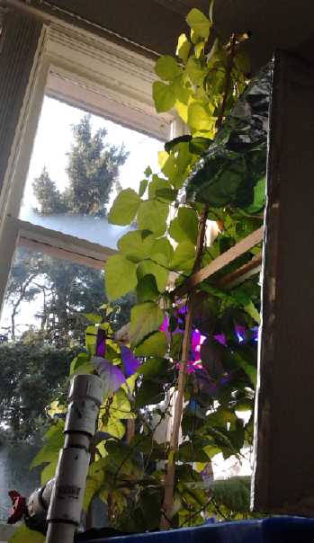
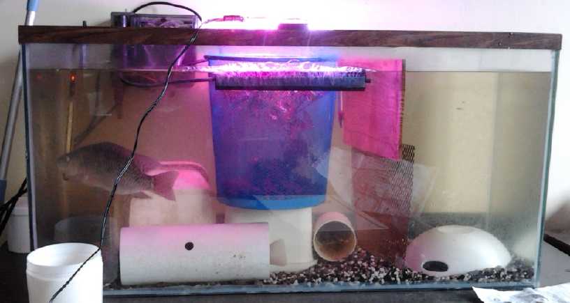 The aquarium with LED grow light, mesh bucket
with plants,
The aquarium with LED grow light, mesh bucket
with plants,
divider with large female (hidden behind mesh) and tiny hatchlings on
right,
bubbler (not submerged), hiding places where
fish don't harass each other...
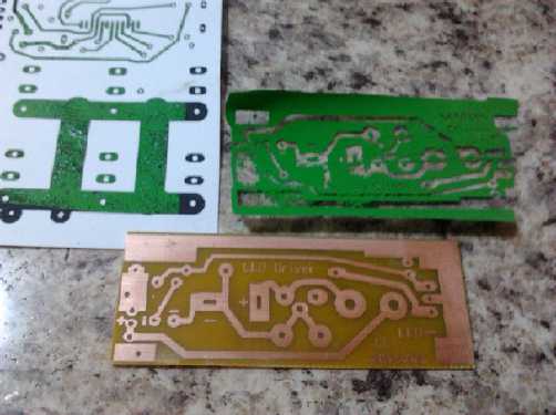 Circuit board for the above grow light came out
better than any previous board.
Circuit board for the above grow light came out
better than any previous board.
The other problem was that the tilapia would eat the
plants. (A reason for an aquaponics setup with the plants outside the
aquarium.) I tried putting one in and it was gobbled down at once, just
like duckweed and stringy green algae are. Another plant wasn't eaten,
but it got uprooted and thrashed into bits pretty quickly. I found a
mesh bucket to grow the plants inside.
With 3 tilapia in the aquarium, at the end of the month
there was a hatchling, and a couple more on February 1st. I hastily put
together a mesh partition to separate the big female and the minute new
fish from the other two, hoping they won't get eaten. But the mesh was
too large and the fry migrated at night. Successful
breeding makes getting a sustainable aquaponics operation look
promising. In a couple of months I should probably start moving the
whole operation from the house to the greenhouse and expand it. Fish
dinners in the fall?
Meanwhile, back at the aquaponics setup, the beans
definitely outgrew everything else, which got pretty much shaded out.
Then one of the three remaining tilapia (the other three now being in
the aquarium) was bit to death by the other two. Apparently putting in
little 'hidey-holes' for the fish isn't just an 'extra', it's essential.
At one point there were four fry, but later I could only
find three. I suspect probably more than one was eaten. On February 4th
I netted them and put them into a bucket floating in the aquarium. Then
I went out to pick up the lead-acid battery that had arrived, and I
decided while I was at it to drop into a nearby aquarium store and get
some small size koi fish food pellets. I ended up breaking down and
buying a 10 US gallon aquarium and paraphernalia for the little fish. I
can see that it's necessary, and maybe more than one, for any real
multi-generation fish growing operation. One guy on youtube had shelves
full of aquariums crammed with different sizes of young tilapia. I
won't get so carried away, but the vision of one old freezer of
water, some plant beds and a pump in the greenhouse is getting out of
control! The idea of tackling brook trout as well in a separate system
is
losing its appeal.
In Passing
(Miscellaneous topics, editorial comments & opinionated rants)
Energy Invention Suppression Cases
We hear occasionally of some new energy device in the
news, which is almost invariably never heard of again. With
continuing
exposure to
the stories and their follow-ups over time one starts to realize
that there's more to it than phony or impractical inventions. Those do
exist, but for more successful inventions and discoveries, there really
is an organized campaign of suppression by those involved in keeping us
using petroleum and degrading the environment - and under their thumbs
- for so long.
I found a web site where many Energy Invention
Suppression Cases were cataloged. The compilation by that name is
by Gary Vesperman. A web search
reveals that it's posted on many web sites. It seems Vesperman did one
in 2006 which was updated in 2007 and maybe 2008 with additional
stories related to
him after publication.
The number of patents said to be classified as "secret"
by the US patent office, and the draconian law applied to inventors of
inventions so classified, if true, indicates
much very valuable knowledge and technology is being deliberately kept
from us, and
that some of our most creative, contributing people are being treated
like criminals
by the gangsters that have the reins of power.
This compilation obviously isn't a complete work. For
example, it
doesn't mention the apparent murder ('disappeared' off a ferry) of
Rudolf Diesel, inventor of "a new kind of internal combustion engine to
run off peanut oil", which then became "runs off petroleum oil". Nor is
the burning down of Edison's factories in December 1914 mentioned. 11
separate concrete buildings out of 14 (IIRC) were destroyed just a week
after Thomas Edison and Henry Ford announced to the newspapers that
they were bringing out a
new electric car that would be "the best thing on the road!" Ford had
put his Model T profits into Edison's NiFe battery factory so they
could mass produce these very long lasting batteries in quantites
sufficient for mass electric car production, and (with lead-acid
batteries being so short lived) the obviously deliberate burning of the
factory buildings destroyed the whole plan. Nor does the name "Chevron
Oil" appear under organizations "involved with Energy Invention
Suppression", despite their holding the companies ('Ovonics' and
'Cobasys') presently preventing (by having acquired seemingly nearly
all
related patents),
manufacture of large flooded NiMH batteries for electric transport,
which are more
robust and less costly than lithium types. (So far the jury's
still out whether the NiMH D dry cells or the lithiums will last longer
in the RX7-EV. The 30 NiMH D cell battery still starts the Tercel after
5 years of use and abuse.)
But of course all the organization names are merely fronts
for a few lawless people behind the scenes giving the orders, with
governments in their pockets and corporations for a front,
committing brazen crimes and getting away with them with impudence and
impunity. Perhaps it's many of the 85 individuals with as much wealth
as the planet's poorest 3,500,000,000 people. They're the real dogs in
the manger who, having no use for hay themselves, stand snarling and
biting on the path and won't let the hungry horses get near it.
The text starts with an introduction with some interesting
statistics:
>>
For energy invention suppression updates, see
http://www.energysuppression.com.
Energy Invention Suppression Case Statistics
Number of Energy Invention Suppression Incidents – 95
Number of Dead, Missing, or Injured Energy Inventors, Activists, and
Associates – 20
Number of Energy Inventors and Associates Threatened with Death – 32
Number of Energy Researchers and Associates Imprisoned or Falsely
Charged – 5
Number of Incidents of Energy Invention Suppression by the United
States Government, Patent Office,
Central Intelligence Agency, Federal Bureau of Investigation, U.S.
Marshals, Army, Air Force,
Navy, Bureau of Alcohol, Tobacco, and Firearms, Defense Intelligence
Agency, S.W.A.T. Teams,
National Security Agency, U.S. Postal Service, Department of Energy,
Department of State,
Securities and Exchange Commission, Food and Drug Administration,
Department of Defense,
Department of Homeland Security, Internal Revenue Service, Rural
Electrification
Administration, White House, Consumer Product Safety Commission, Small
Business Administration, and
Canada’s Royal Canadian Mounted Police – 59
Number of Inventions Classified Secret by U.S. Patent Office – 5000
Number of Incidents Involving Oil Companies – 9
Names of Companies, Banks, State Agencies, Private Groups, and
Universities Involved with Energy
Invention Suppression – Standard Oil, Zapata Petroleum, Atlantic
Richfield, Exxon-Mobile,
Shell Oil Company, General Electric Company, Yakuza, California Air
Resources Board,
Organization of Petroleum Exporting Countries, Wells Fargo Bank, Ford
Motor Company,
General Motors Corporation, Massachusetts Institute of Technology,
Queen of England,
Kollmorgan, World Bank, Rockefellers, Carlyle Group, and Bush
Family
<<
Patent System: Far More Disgraceful than I Ever Dreamed!
I don't want to start in on the whole catalog above, but
longer-time readers may remember me writing about The Disgrace of
the Patent System (TE News #28) and later occasional related notes
or updates. But here, from the report above, is a
whole new aspect that was
unknown to me:
"The United States Patent Office has classified 5000 patents, an
unknown number of which relate to energy. Their helplessly shackled
inventors will be jailed for 20 years if they work on, develop, make,
sell, write about, or even simply talk about their inventions."
Keep your proud accomplishment secret for the rest of your
life, OR ELSE! -- I don't remember seeing this anywhere in patent
related literature. Is the US government not proud to boast about this
fine protection of the citizenry from devious inventors and their
dangerous inventions? What were all those inventors working on, neutron
bombs? Doubtless they were all taken by complete surprise by the
response to their patent application. Think of that next time you think
of
applying for a patent for an exciting new energy invention - or
anything else with a potential for challenging the status quo! It's far
better just to publish, "open source". Indeed, it looks like that's the
only way a lot of valuable information would ever become known were it
not for the coming collapse, wherein such repulsive rules written by
and for the greedy will finally be cast aside as slumbering humanity
awakens and quickens intellectually, morally and spiritually, discards
economic and political tyranny, and a golden new age begins to dawn.
Later Words of Woodrow Wilson on creation of the US Federal Reserve
It seems a 'quote' has been on the internet, attributed to
US president Woodrow Wilson. Wilson's election campaign was partially
financed by the would-be banksters, with the extraction of a promise
that a private US central bank would be created if he was elected. It
seems that later he regretted what he had done - probably after events
had had some years to develop, when he would have had no more influence
or power to change what he had done.
In discussion about the authenticity of the quote, it
appears that the first two sentences (if Wilson said them at all)
probably come from his personal diary, while the remainder isn't a
single quote, but is stitched together from two or possibly more
sections of Wilson's book: The New
Freedom: A Call for the Emancipation of the Generous Energies of a
People (New York and Garden City: Doubleday, Page &
Company, 1913). Thus, as with
Jefferson's quote(s) on the evils of private central banking, it would
appear the writer probably took some license combining various words by
Wilson into a single "quote" without an explanation. At least a
footnote was due, if not quotes around each segment separately. But as
one of the discussers wrote, "It doesn't really matter who said
it, the point is that it is true,
the federal government and federal reserve create [constitute] a
monarchy as opposed
to a democracy." The 'quote', with the
(apparent) segments separated by quotes reads:
- "I am a most unhappy man. I have unwittingly ruined my country."
"A great
industrial nation is controlled by its system of credit. Our system of
credit is concentrated. The growth of the nation, therefore, and all
our activities are in the hands of a few men." "We have come to be one
of
the worst ruled, one of the most completely controlled and dominated
Governments in the civilized world, no longer a Government by free
opinion, no longer a Government by conviction and the vote of the
majority, but a Government by the opinion and duress of a small group
of dominant men." -Woodrow Wilson
In this same book, Wilson is also said to have written:
- Since I entered politics, I have chiefly had men's views confided
to me privately. Some of the biggest men in the United States, in the
field of commerce and manufacture, are afraid of somebody, are afraid
of something. They know that there is a power somewhere so organized,
so subtle, so watchful, so interlocked, so complete, so pervasive, that
they had better not speak above their breath when they speak in
condemnation of it.
Just how far back does this
stuff go, anyway? ...to the Lucifer Rebellion of 200000 BC?)
My Financial Gripes
At Christmas my aged mother once
again helped me out
financially (Thanks Mom!), which is well because Canada Revenue Agency
not only hasn't paid me yet for 2013, but they
phoned (not until 2015! -- I already get the money a year after I've
done
the work. This makes it two years.) and indicated they are disallowing
about 1/2
my total refund claim for 2013 of about $22000, leaving only around
$12000. And I understand I'm not the only one being given this
treatment. With the falling economy reducing government revenues, I
guess they're cutting everything they can cut without causing a public
uproar. (And food prices seem to have nearly doubled in the last few
years.)
Consider (IMHO):
* The considerable amount of actual inventive research and development
work I've been doing, and then
writing up and publishing that
work - making it available on line at
www.TurquoiseEnergy.com so others can make use of it, and
replying to e-mails of technical questions, suggestions and ideas
worldwide.
* Several items of this work - starting with two new battery
chemistries and superior electric motors - are potentially worth far
more than all of the total assistance I've received.
* a large portion of the refund I receive each year, I have to spend on
materials and supplies in order to do the work.
* I do 2 or 3 or more weeks of paperwork each year on CRA's schedule
(complete with fines and interest charges for every mistake or
omission) to justify
and enable this rather meager tax credit.
* that it seems to me the amount claimed is probably less than a
typical person's pension
- which needs no justification and whose use is completely
discretionary by the recipient.
Delaying it so long and then cutting it in half seems
rather
harsh. This is after all the bulk of my income. Kids are encouraged to
be
creative and inventive in school and university, but they graduate into
a society where those with money and power look on change and invention
as a threat, nowhere more than in the field of energy and reduction of
petroleum dependence. Until one finally starts to realize this, it
seems incomprehensible that one's fine inventions and plans always seem
to fall on deaf ears when looking for backing, when mass production and
paradigm
changes
would be so simple, and that every business
trying to create fuel-less transport seems to somehow fail. But the
internet is
unmasking many hidden agendas and helping raise the world's
consciousness about the reasons of senseless greed and corruption
originating mainly with a few people that cause some
things to never seem to change.
Where I have been eking by before, the reduced amount for
2013 will multiply into further major reductions for 2014 and beyond.
(since the
less money Turquoise Energy receives, the less it's able to provide a
'salary' to me and so the less I have to
reinvest in needed materials and supplies, so any reduction ripples
through and
further reduces the totals for subsequent years.) This makes
working for new discoveries and the development of new renewable energy
products mainly for mankind's overall benefit financially unfeasible.
In fact, last summer I mortgaged my house of 37 years to help make ends
meet.
Having now hit age 60 with a large new debt and
unexpectedly little income, I suppose I'll apply for Canada Pension,
but since my employment history is so spotty (having made more than one
attempt to bring
fine things to the world, each terminating some somewhat mundane but
paying
employment), it'll probably be a pittance. But in today's
economically declining world, who can really predict the future very
far? And if the unipolar
motors are successful, or if I figure out how to make practical
batteries with the fine chemistries I've discovered, perhaps there'll
be money to be made somehow.
Then I found the CHIP (Canadian Home Income Program)
mortgage
for those
over 55, and I hope and expect to switch the mortgage to that. Instead
of paying
money monthly, the interest accrues as an increasing claim against your
house, to be repayed when your house is sold - when you move or move
on. And (barring any hanky-panky) CHIP will never foreclose while the
owner(s) live. In fact, one can draw a small monthly income from one's
home equity,
always provided the estimated amount that will eventually be withdrawn
is less than half the value of the house. With this and every other
little thing, I think I'll be able to continue. Perhaps it's well I had
no children?
But it looks like losing the equity of one's home in
retirement is
pretty much the way now for the majority, since property taxes are too
high for the retired to pay. Instead of raising the homeowner's grant
(to meet the income demands of ever more profligate municipal
governments as well as inflation), which was originally supposed to
cover typical homeowners' entire taxes except on especially large and
luxury estates, the province offers only "tax deferral" to the retired,
to be clawed back from the estate. The kids may get some equity money,
but
they can't inherit their parents' house. In effect it goes to the banks
and to
the government for resale - or rent - to an increasingly impoverished
public.
Newsletters Index/Highlights: http://www.TurquoiseEnergy.com/news/index.html
Construction Manuals and information:
- Electric Hubcap Family Motors - Turquoise Motor Controllers
- Preliminary Ni-Mn, Ni-Ni Battery Making book
Products Catalog:
- Electric Hubcap 7.2 KW BLDC Pancake Motor Kit
- Electric
Caik 4.8 KW BLDC Pancake Motor Kit
- NiMH Handy Battery Sticks, 12v battery trays & Dry
Cells (cheapest NiMH
prices in Victoria BC)
- LED Light Fixtures
(Will accept BITCOIN digital currency)
...all at: http://www.TurquoiseEnergy.com/
(orders: e-mail craig@saers.com)
Daily
Log
(time accounting, mainly for CRA - SR & ED assessment purposes)
1-6: Sick.
4th: Finished December newsletter/report (#83)
5th: Made wooden pieces to mount coil in aluminum unipolar motor
controller box. The coil is
taller than expected and it's a very tight fit. Measured resistance of
#8 AWG nickel-brass wire in order to use a piece of it as a shunt. It
seems like about 5 milliohms per inch. If I use 3 pieces 3" long to get
5 milliohms, the heat from high currents will be much more spread out.
8th: Bought 135 amp DC circuit breaker.
9th: Wound the 6 coils for the unipolar motor. Touched up the epoxy on
the motor body and painted it with 2 coats of polyurethane paint (still
needs more).
10: 2 more coats of paint. Cut slots in optical rotor position sensor.
11: Painted coils with nanocrystalline ilmenite in "Plasti-Dip flexible
rubber coating" thinned with toluene, coated that with dry ilmenite
powder.
12: Drilled other end plate for stator side (first one was accidentally
slightly skewed). Fitted stator end bearing.
13: Wired motor coils.
14: Purchased cable for controller to motor. (4 wire #8 'cab tire' -
not easiest to come by.)
15: Considered problem at length, thought up a special clamp, made
small hole to feed large wire into motor.
16: Clamped & wired cable into motor.
17-18: weekend off
19: Started fitting everything together.
20: Repaired NiMH battery for electric drill (made in about 2010), and
wrote it up for this newsletter. (Another demonstration of what can go
badly wrong if it isn't done right, and that 'right' isn't obvious to
the uninitiated. Education is the key to so many things!)
Decided to test unipolar motor optics system before motor assembly.
There were in fact problems, which I spent the rest of the day
correcting.
21-23: some days off (working on financial things to stay solvent).
24-26: Made next flat panel LED grow light: blue 425nm, red 660nm.
(Gotta get the build time down to 2 hours!)
27: see 21-23.
28: Finally resumed unipolar motor construction. Body bolt holes - had
problems with wires covering the holes.
29: Made new motor shaft. The existing one I thought would do was too
short - it wouldn't have worked easily in the outboard motor.
30: Assembled motor except some machine screw case clamps, which didn't
fit properly.
31: off.
Feb 1: Made divider screen for aquarium as there were baby tilapia
fish. They needed to be protected from the big ones.
Feb 2-5: writing newsletter.
Electric Hubcap Motor Systems - Electric Transport
Unipolar
('monopolar', 'homopolar') Motor Controller
After New Year I found Smith Bros. open. They had my
'ideal' size copper bar for the motor controllers in, .125" x .5", and
I bought a length sufficient for several controllers.
I turned a couple of wooden pieces to mount the energy
recovery coil on in the aluminum box. The coil is taller than expected
and it's a very tight fit.
Then I measured resistance of #8 AWG nickel-brass wire in
order to use a piece of it as a shunt. In order to measure very low
resistances, one passes a known current through the material and
measures the voltage along any desired length of it. So with 1.0 amps
from the lab power supply going through the nickel-brass wire, each
millivolt corresponds to one milliohm. It seems like about 5 milliohms
per inch. 100 amps would thus result in 500 millivolts across the shunt
and a peak of say 200 amps would be one volt. 200 amps times 1 volt is
also 200 watts. Hmm!
If I use 4 pieces 2" long to get 2.5 milliohms, the 100
watts heat from 200 amps will be much more spread out - 25 watts per 2"
piece. That at least shouldn't glow red hot!
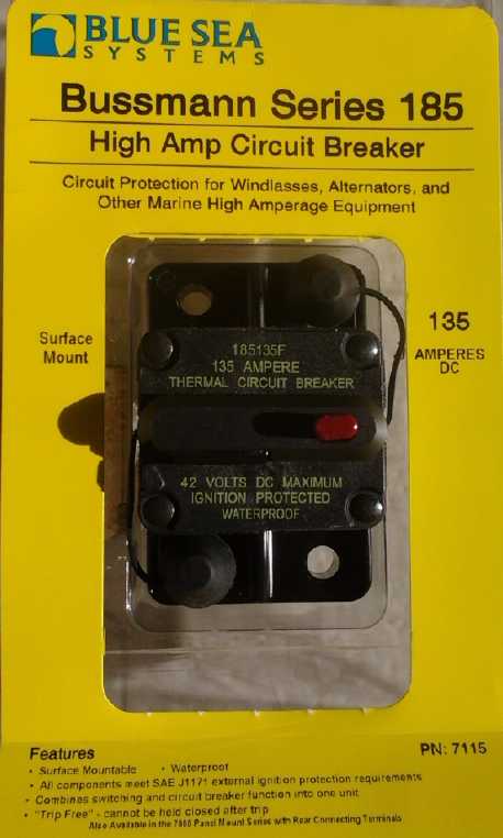 On the 7th I
found a surface mount 135 amp circuit
breaker. My original conception was to put everything in the motor
controller box, that it would be the wiring box where everything
terminates. Probably that made sense with an add-on 'hubcap' motor
system. Now I'm gravitating towards the the typical EV car system,
where "under the hood" is the wiring box. Everything is there out in
the open, but usually with some attempt to put a bottom cover in to
enclose the whole under-hood area and reduce or eliminate the dust and
crap that gets in from the wheels and the road.
On the 7th I
found a surface mount 135 amp circuit
breaker. My original conception was to put everything in the motor
controller box, that it would be the wiring box where everything
terminates. Probably that made sense with an add-on 'hubcap' motor
system. Now I'm gravitating towards the the typical EV car system,
where "under the hood" is the wiring box. Everything is there out in
the open, but usually with some attempt to put a bottom cover in to
enclose the whole under-hood area and reduce or eliminate the dust and
crap that gets in from the wheels and the road.
I'm wondering if there might be some way to boost the
recharge pulses with lambda rays... or if perhaps that's how Bedini's
units actually gave such amazing performance. It's rapidly switched,
rather high voltage pulses. That's seemingly the start of the right
conditions for capturing the rays. Hmm, what components might be
employed to give the correct effects?
Electric Caik
Unipolar BLDC Motor
Motor, Stator Side (Gap is air intake, to be covered with furnace
filter material)
Obviously a unique motor
and its controller are a unique set, and neither can be used without
the other. I got back to the motor,
untouched since November, toward
the middle of the month. It was virtually finished by the end.
On the 9th I wound the 6 motor coils, touched up the
epoxy on the motor body a bit with the left over epoxy, and painted
on a couple of coats of the yellow polyurethane paint, somewhat
thinned down. If I don't thin it down, it's so thick as to form a
somewhat loose skin that peels easily. If I do, it needs
several coats (and still looks spotty). I added two more the next day,
when I also cut and
filed out the slots in the rotor position optical interrupter. Since
there are four like magnets, there are four slots with four solid walls
between them, as evenly spaced and sized as I could manage.
I note in passing that if this magnet arrangement proves
suitable, it's yet another saving for the unipolar design since the
magnets are quite expensive and it uses only half as many as the
bipolar type.
On the 11th I painted the coils with nano-crystalline
ilmenite in "Plasti-Dip rubberizing compound". It's been so long since
I did it I referred to TE News #54 for instructions. I never did find
out whether ilmenite in Plasti-Dip is just as good as ilmenite in
sodium silicate ("water glass"), but this time I decided to try and
find out. After all,
the nanocrystalline ilmenite is the active ingredient, and why would
it act differently in one solidified suspension than another? It
certainly has that same rich chocolate color.
Once I have
the
motor running and idle currents for various RPM.s recorded, I'll take
it apart and add a coat of ilmenite in sodium silicate, and see how
much difference it makes. It may take more than one motor to really
tell, tho, since a second coat in Plasti-Dip might be just as good as
one in sodium silicate.
The Plasti-Dip was almost hard, shrunk into the bottom of
its "coffee can" style container. I used a lot of toluene to soften it
up again. In this I finally realized why my chem lab fridge has been
stinking of solvent for all this time: the Plasti-Dip was slowly drying
out and releasing the vapor. I had long forgotten it was there until I
needed it. (I kept tightening the lid on the toluene can, to no avail.)
I was
wondering even when I bought it how they expected a
liquid in such a container not to dry out. Sure enough, it's sold in an
unsuitable container. If I hadn't put it in the fridge it would have
been totally
hard and useless by now. After I had softened it up to a workable
extent I
transferred it to a glass jar and added ilmenite powder and then more
toluene to get it to a reasonable consistency for use. All this
annoyance took longer than actually painting the coils.
In order to have the sodium silicate adhere later, I put
each wet painted coil in a paper bag of ilmenite powder, holding it by
its
wires, and shook the bag to get dry ilmenite particles on the surface.
(TE
News #54 says that's what it sticks well to.) If as I suspect the
sodium silicate proves to be unnecessary, I'll just stick with the
ilmenite in Plasti-Dip paint alone; two coats if it seems to help, and
forget the dusty dry powder on the outside.
On putting this Electric Caik motor together (unipolar or
not), I decided that I had erred a bit in judgment on the original
diameters.
(Well... the whole original motor was after all developed and working
in about 3
months.) Not that it didn't work, and well. The selected rotor size of
7.5" puts
the coil centers at 2.75", and the bearing flange and mounting bolts in
the center get in the way of the inner sides of the coils. Plus there's
very little room for the rotor position
sensing circuit board. And the coils are so close together that there
wasn't enough room for a ribbon cable to pass between two cotton
insulted coil wires in the first motor - the thinner coated plastic
ones
had to be used. Of course the cotton insulated was old surplus wire,
but that's how very tight it all is. On the other hand, I made a second
small misjudgment: there's enough room in the rotor compartment for a
larger
rotor, even up to 8.0". Thus it could have a slightly larger rotor
without
changing the external size of the motor. And there's room in the stator
to move the
coils outward at least .2".
The available 7.8" disk brake rotor that I purchased from
Princess Auto comes to mind, and I could easily order waterjet-cut
rotors with that diameter instead of 7.5". New molds and drill jigs
will have to be
made that move the coil mounts outward by .15". This would leave a .3"
wider
space
in the center and a little more space between coils. I think it's
worth it if more of these motors are to be made - which will probably
be the case if (as I expect) the unipolar motor and controller prove
superior. And
then I expect some people will want to buy molds so they can
manufacture the
motors themselves, so they might as well be improved molds.
Speaking of drill jigs: I had originally drilled holes for
the pressed bearing holder by hand. The positions were slightly off
clockwise. It didn't really matter for the bearing, but when I did the
rest of the holes after making the jig, they accidentally got lined up
with the bearing holes instead of the coils. And they do matter. They
were off just far
enough to fit noticeably crooked. I decided to reverse the
two end plates by drilling the same (stator end) holes in the other
one. This time, I discovered the bearing holes, now in the template
(and filed square for carriage bolts), lined up with three coils
instead of each being between two coils. The heads of the bolts hit the
wire. I corrected the mistake in the G-code file in case there's a next
time (ie, without making it .3" larger... or so I don't simply
forget and duplicate the mistake when I do make it wider), and drilled
and filed
new holes by hand in the present unit.
 Above: Optics board mounting
Below: how it fits in and interfaces with slotted drum.
On the evening of the 12th I thought for a moment I had a
great idea: mount the rotor position sensor at the very top, behind the
rotor, instead of at the very bottom. The PCB would be mounted inside
the
lid, the last thing that's put on when assembling the motor. But when I
checked I found there was absolutely no space there. And why should
there be? Any space beyond the rotor would otherwise be making the
'cake' thicker for no particular reason.
That seemed to leave getting it to fit somehow in the
stator compartment, or making a much longer shaft and mounting it
externally on the stator end. There sure ain't much room for the wiring
in the crammed center of the stator compartment! I finally decided to
put the coils in "upside down" to my usual, so the wire ends were next
to the middle instead of the outside. That should leave maximum room
for the optics at the bottom, provided the wiring was kept very tight.
I got the coils wired on the 13th. It would have gone a lot faster with
a little more room to work in, and while the coils faced in, I did end
up putting some wires around the outside. Only a week later did I
realize those were covering up some - too many - of the screw holes for
the plastic machine screws to hold the motor together.
 With every
coil there's that annoying wire coming out from
the
middle, the inside of the spiral, sticking out to one side and making
the whole coil fatter. With
heavy #11 AWG wire, that's a lot fatter. I decided to gouge slots in
the inner wall to accommodate this wire, so the coils would lie flat
against the inner wall to interact optimally with the spinning magnet
rotor on the far side.
With every
coil there's that annoying wire coming out from
the
middle, the inside of the spiral, sticking out to one side and making
the whole coil fatter. With
heavy #11 AWG wire, that's a lot fatter. I decided to gouge slots in
the inner wall to accommodate this wire, so the coils would lie flat
against the inner wall to interact optimally with the spinning magnet
rotor on the far side.
 I figured the best wire to use between
the motor and the controller would be #8 AWG "cab tire", and it needed
4 wires instead of 3. I bought some on the 14th. Then I looked at the
fat wire and the thin, narrow motor wall it was to pass through. The
wire diameter was larger than the available wall width, and there was
about zero room inside for the inside end of a wire clamp. (Expanding
the center diameter would only make this aspect worse.) I pondered the
problem until the following evening, when I finally came up with a
plan: The outside rubber of the "cab tire" would be cut off just before
the motor - there just wasn't space for it through the wall or inside.
Just the four fat #8 AWG wires would poke through a square-ish hole.
Since the edges of the hole were fairly soft, that was acceptable. On
the outside, a pipe clamp would clamp two "angle brackets" (or
something along those lines) to the wire to form a flange on each side
of the wire. The flange would be screwed to the motor wall, the whole
forming a wire clamp with no protrusion into the motor. And I found
'ideal' angle brackets in a drawer with a surprisingly short search,
left over from early motor designs.
I figured the best wire to use between
the motor and the controller would be #8 AWG "cab tire", and it needed
4 wires instead of 3. I bought some on the 14th. Then I looked at the
fat wire and the thin, narrow motor wall it was to pass through. The
wire diameter was larger than the available wall width, and there was
about zero room inside for the inside end of a wire clamp. (Expanding
the center diameter would only make this aspect worse.) I pondered the
problem until the following evening, when I finally came up with a
plan: The outside rubber of the "cab tire" would be cut off just before
the motor - there just wasn't space for it through the wall or inside.
Just the four fat #8 AWG wires would poke through a square-ish hole.
Since the edges of the hole were fairly soft, that was acceptable. On
the outside, a pipe clamp would clamp two "angle brackets" (or
something along those lines) to the wire to form a flange on each side
of the wire. The flange would be screwed to the motor wall, the whole
forming a wire clamp with no protrusion into the motor. And I found
'ideal' angle brackets in a drawer with a surprisingly short search,
left over from early motor designs.
(Later when I had it all done I realized that the hole
could be a slot, and then the entire coil-cable wiring assembly could
be completely removed from the stator. Then when I was drilling
mounting holes in the body, I did nip the top off the hole and set it
aside so I wouldn't drill into any wires.)
Later I looked at the old motor - how had I done that
one? It seems I ran the 3 actual coil magnet wires to the outside of
the motor
through a small hole, and then immediately they ended at a 3-pin APP
connector. That way they took up no extra room inside. Mechanically
inferior but it works.
With this motor the slotted drum takes extra space around
the shaft that was previously available for the wiring. I wasn't going
to have a
connector, just have the cable sticking out of the motor, to be bolted
to the motor controller connections at the other end. It's already
difficult to plug in and unplug the 3 wire APP connectors. 4 wires
could be almost impossible. But what was the reason for wanting a
connector? Originally it was so the always changing Electric Hubcap
motor and torque converter on the outside of the wheel could be plugged
into the motor controller inside the car without bolting and unbolting
wires every time. Although I still want to do that, it's not what's
happening at this time, and every connection is another potential
trouble point.
On the 16th I went to wire in the cable and realized I
didn't have any wire sleeving big enough. So I first had to go shopping
- again. While I was out I remembered the motors also needed 1"
carriage bolts - I was using some that were really too long. I
congratulated myself on potentially saving another trip. When I got
home I found I didn't have a pipe clamp the right size and cursed
myself for not checking before I left, and so needing another shopping
trip. I could do the wiring without immediately clamping the
wire, but I had
to do a couple of unrelated things anyway, so off I went again. (It
was almost 10 miles/16 Km total that day for the RX7 EV, with the
weakest
battery as
usual dropping almost to 10 volts on the last up hill home in spite of
a 3 hour charge between trips. The float
charge system isn't bad, but it really needs a whole day for a full
recharge. When I picked it, I didn't know the car would need a full
charge
for most every trip. ...Well, it's a reminder why I'm doing the
unipolar motor as well as the ultra-efficient torque converter
transmission: they're
supposed to improve on that in a big way!)
After taking the whole weekend off (as far as the motor
was concerned), on the 19th and 20 I started trying to put the motor
together. I decided to test the optical assembly first, and there were
problems with it. Owing to the thickness of the plastic drum and my
desire to maintain a good clearance with the delicate electronic parts,
the LED.s and the phototransistors were a considerable disctance apart.
What I hadn't considered was that the little bumps on the sides were
close focus lenses. Putting the parts farther apart not only reduced
the light owing to distance, it put it way out of focus. I finally
ended up putting in a 470 ohm resistor instead of 1000 ohm to double
the current to the
LED.s, and bending the component leeds to get the pairs closer
together. As
long as the drum is in the right place (and really there's no reason it
shouldn't be), it won't hit the optical components. But the solder on
one of the phototransistors broke loose when I bent it. I repaired that
but it still didn't work. Finally I had to replace the transistor with
one of several somethings out of a box that had no indication whether
they were LED or phototransistor, and which may or may not have been
sensitive to the existing LED's light wavelength. Luckily the first try
was a winner. But I shot much of the 20th on it. Now it's all up to how
much load the MC33033 motor controller chip puts on the
phototransistors, because they won't drive much with the low LED light
levels. And it's up to the LED.s with unknown specs not to burn out
with the extra current. (If it doesn't quite work I can try even more
LED current to further increase the brightness a little. After that I'm
about out of ideas.)
Those optics came out of some old computer mouse. For
future units I purchased some optical interrupters made to operate
at the wider gap. But it looks like they're too tall for the available
space - ugh!
When I was ready to bolt everything together, I suddenly
realized the wires inside were covering up many of the case screw
holes. Ouch! Who would have thought? One simply assumes, "Oh, wires,
they bend. They'll stuff in there somewhere." But there really wasn't
enough room inside the motor to connect the fat #11 coil wires
anywhere. This put me off for some days, looking for inspiration. I
finally decided I would put the rotor cover on using 2" nylon machine
screws as screws instead of 3" ones as bolts, making the holes in the
motor body smaller so they'd thread in instead of sliding through. That
way they didn't have go through to reach nuts in the stator space at
all. Once again, not ideal but expedient. I bolted the stator side
together. (28th)
On the 29th I made a new shaft. I had hoped to use an
existing 6" shaft, but it needed to be 8" to fit the same in the
outboard as the present motor. Milling the keyway slots is time
consuming. (Doubtless a pro would work faster?) The next day I fitted
the magnet rotor and slotted drum on the shaft and assembled the whole
motor.
Everything went fine until it came to the body screws. I
thought
I had drilled them 7/32" to thread in, but the 1/4" nylon bolts pushed
right through without turning them. Oops. Anyway, it went together well
- the rotor turns freely without hitting anything, and there's no
indication of any parts hitting each other in the optics system.
On the 31st I figured out what to do: dip some metal bolts
in wax, wrap them in thin polypropylene cloth, paint them with epoxy,
and push them into the bolt holes (which will also be 'primed' with
some more epoxy). The PP/epoxy should adhere perfectly to the PP/epoxy
motor body. When the epoxy sets the waxed bolts should turn out easily
and then the nylon ones can be put in to fasten the lid (rotor end
'bell') on. At that point the motor will be finished.
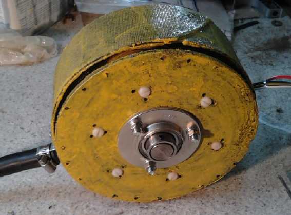
Rotor Side (before bolts)
...& waxed threaded rods
Vehicle
Transmission Thoughts and Ideas: RWD vs FWD, gear + belt
It seemed to me, as I
wondered why I get such poor economy
and range from the RX7, that front wheel drive vehicles with transverse
engines must produce more efficient conversions than rear wheel drive
vehicles or vehicles with front-rear oriented engines. (Another aspect
is battery capacity, see next article.)
The rear drive
shaft & axle adds a little weight, but the main reason would be in
the differential. I thought, in the front wheel drive vehicle with
transverse engine, a
simple spur gear connects the transmission to the differential. While
I've found no definitive info, this gear surely has less friction than
the bevelled gears needed to translate the front-rear drive direction
to
the crosswise axle direction. (Wikipedia says the spur gear has less
friction
than helical gears, but there's not much other info on relative
efficiencies.) In a gas car, who really notices? When it's
electric, a few percent extra drag shows up as some extra amps and some
reduced range which would probably be noticable if they could be
directly compared.
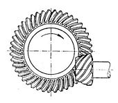
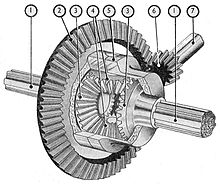
Left: Differential turned by straight spur gear (FWD, transverse engine)
Center & Right: Two variations on beveled gears. (RWD or front-back
facing engine)
The 3 gears within the differential are of little consequence to
efficiency because
they only turn against each other, and slowly, when the vehicle is
turning right
or left.
Later I went and looked at the Sprint differential's original gear:
Oops, it's helical - more friction than a spur gear. (Doubtless
quieter.) That takes some of the value out of my thought. How much I
don't know, because I don't know typical losses/efficiencies for
various types of gears.
But further considering the theme... there's another thing
I'm pretty sure of: Some conversions are done by permanently setting
the manual transmission in 2nd gear (or 3rd?) as a fixed ratio
transmission. This gets rid of the clutch and makes driving easier, but
it does nothing to improve the efficiency of the lossy transmission
(unless perhaps it is disassembled and all the unused gears are
removed). A substantially better result is doubtless obtained by
replacing the entire transmission with a single planetary or other
gear, as I have seen done. Most commercial EV.s also seem to use a
fixed ratio gear. But for conversions this either requires (a) a rear
wheel drive vehicle or (b) that the FWD differential be incorporated
into the new gear setup, which would require a custom housing, or
(c) one motor on each front wheel. It also needs a motor capable of
running at high RPM.s and probably with extra power to get sufficient
torque from a stop. On the highway the RPM.s are highest,
reducing efficiency at high speed.
Presumably still better than a single gear would be a
single flat belt or poly-V belt (almost 99% efficient!) with pulleys of
the desired ratio between the motor and the drive shaft or
differential. As I thought about this, a new design came to mind.
One could have a two-speed transmission where the motor
would pivot, with a "clutch" pedal or else a stick shifter. When the
pedal was
pressed, the motor (shaft) would be pushed toward the transmission
shaft. This would slacken a drive belt (flat or poly-V) and also engage
a pair of gears. The gears would have a high ratio for sufficient low
speed torque to get the vehicle moving. They would be something like
starter motor gears where one is very small and the other very large.
Since the gears would only be used to get the vehicle moving and not
for high speed travel, they would (I expect) only need to be greased
rather than run in a bath of oil.
Once the vehicle was moving 10 or 20 or 30 KmPH, the
"clutch" pedal would be released. This would disengage the gears and
the spring would tighten the drive belt between two pulleys, which
would be right next to the gears but a different ratio. The ratio of
this drive would be suitable from the switchover speed up to highway
speeds, with substantially lower RPM.s than if it had to have torque
for starting moving. Of course, the belt needs no lubrication, and it's
so efficient it would hardly generate any heat.
Of course the variable torque converter is best. After all
this time, I might just go for "simplest to make" - as long as it's way
less lossy than a typical auto transmission.
Electric Mazda
RX7: NiMH "Battery Upgrade"
One factor in
conversion effectiveness is the batteries.
Typically commercial EV.s
have say 22 or more KWH of batteries; a few have 16 KWH. The RX7
with ten 100AH batteries, 128 volts, has only 12.8 KWH, and so the
current demanded per battery capacity is that much higher, and voltages
start dropping off before some of the batteries' charges are really
getting low. The weakest two batteries show this up after a few miles.
They actually still have charge and the voltages rise back up to match
the other NiMH.s once it's parked. The others would go somewhat farther
before the same objection would become as pronounced. And on level road
where a lighter touch could be used on the pedal, they would all go
longer. But we hardly have such a thing on this island.
As mentioned previously,
the RX7 last summer was using around 1.9AH/mile (266WH/mile @140V) with
11 batteries. In the cold weather and with only 10 batteries, it's
using around 2.3AH/mile (300WH/mile). In accordance with the higher
currents, the battery voltage drops more and drops faster per mile.
On the 14th I drove almost 5 miles (buying cable for the
unipolar motor), and voltages
on the 90AH NiMH.s were dropping to 10.x V going up hills on the way
home.
After I stopped they all came back to 12.3 volts or more, so they still
had charge for at least 2 or 3 more miles. But they would soon have
been
dropping below the 10 volt "deterioration starts here" mark, and also
at 10
volts they're giving 20% less power than at 12 volts.
Having soldered together six 50AH, 12V, 50 D cell, NiMH
batteries, which are used doubled up in the RX7 as three 100AH, 12V
batteries, I still had the two original 90AH NiMH batteries in long
pipes, 10 D cells per pipe.
Earlier, these had started as three 60AH pipe batteries,
but those didn't seem to have enough current drive for high load
conditions, and I changed them to two 90AH. But even these (now a
couple of years old) start to
lose more voltage than is desirable after 3 or 4 miles of driving, and
I'm starting to think at least 120 to 150 AH batteries would be better
and give
a lot more range before the voltages start to fall off. And the pipes
take extra space. I could install three soldered together batteries
where the two pipe batteries now sit.
My plan has been to take the pipe batteries apart and make
them into doubled-up 50 AH soldered batteries like the other new ones.
But it's a lot of work for a minimal result amid many competing
attractions. When could I get around to it?
I started thinking about putting two 3D printed 12V NiMH D
cell battery cases on top of the 90AH batteries as a temporary measure
to make them 100AH. But I only had four sets of 10 D cells
left. These sets were in the five short pipes of 2 cells each,
connected together to
make 12V. These were in the solar PV system. I disconnected two and
took them down to the car. They seemed to fit in the box on top of the
other pipes, and the hood still closed. I tucked one under each of the
two straps holding the whole assembly box, and put in a small piece of
wood to hold them apart, lest they come together and wire connectors
possibly short together. This seemed very workable - much better than
doing the printed boxes.
So I went up to the electronics lab to make four cables to
connect them... and found in the drawers four suitable #10 wires with
end connectors. A couple were a little long, but they were already
made. I took these back down to the car and hooked it all up. It was
all done in a little over an hour. No shorts, bruises or catastrophes.
That solved that for now!
So now there are five 12V, 100AH NiMH D cell batteries of
one sort or another, two 16V, 100AH Lithium-ion batteries, and three
12V 'frame 27' lead-acid batteries of similar capacity - the last ones
that are still working really well, so far, after less than two years.
That's
only 10 batteries and 128 volts. Another 12V battery of any sort would
be very desirable to reduce currents and add capacity, but I'm becoming
reluctant either to get another short lived lead-acid or to spend money
I don't have on more NiMH or lithium cells.
A drive in the evening with the new arrangement showed the
same batteries are still weaker and the formerly worst one is
still the worst - and by about the same margin. The theoretical 5 x
100AH NiMH.s are not all equal. There's still the possibility one or
more of the tubes of cells in the weakest one aren't connecting
properly. The one recently
made
of all new cells is the strongest. None of them get right up to
14.0 volts when charged - just 13.8 or 13.9. I don't think they're
quite as fully charged as they might be. I should adjust a charger or
two and see how much difference it makes. On the other hand, the
voltage need only be a little too high to keep current flowing and get
them hot after
they're charged, with potential for degradation or damage. (See "New
NiMH Battery Pack Blow-up" under the
battery/storage section below. I'm never really sure whether the Mazda
battery topics should be under "Electric Transport" or "Electricity
Storage" - the subjects are so interlinked.)
"Green" Electric Equipment Projects
Aquaponics
& LED Grow Lighting Project
Drain-down grow bed with... Beans!
(mid-month. They're bigger now.
now how about some flowers and beans?)
 Like any living system, the aquaponics things grew at their own pace.
Aside from the slowly growing fish, the beans were amazing. They were
just one of several types of seeds I planted, but they took off and
soon outgrew everything else, and had so many leaves they blocked most
of the light from the LED lights. That's better than they grow in my
garden. That's kind of cool, but so far there's just leaves - no sign
of flowering to make beans. And it meant nothing else could be expected
to do much. Under the beans there's just a few yellowy leaves of hardly
identifiable herbs and vegetables.
Like any living system, the aquaponics things grew at their own pace.
Aside from the slowly growing fish, the beans were amazing. They were
just one of several types of seeds I planted, but they took off and
soon outgrew everything else, and had so many leaves they blocked most
of the light from the LED lights. That's better than they grow in my
garden. That's kind of cool, but so far there's just leaves - no sign
of flowering to make beans. And it meant nothing else could be expected
to do much. Under the beans there's just a few yellowy leaves of hardly
identifiable herbs and vegetables.
The bell syphon in the drain-down bed seemed to work worse
and worse with time. Once the bed was full it dribbled and dripped for
some time before it finally "tripped" and drained, as if the water was
barely on high enough to get it to flush. Then the flush didn't seem as
energetic as usual. Once the bed was drained, it dribbled and dripped
for a while, as if the water was running almost too high to allow it to
finally stop syphoning. This was annoying since I can hear it
misbehaving from my bedroom. Surely it couldn't be turned up too high
and down too low at the same time! I finally realized what the problem
must be. I took the bell syphon apart and sure enough! the beans had
grown some long roots under the outer cover, up into the cover pipe,
and down the downspout.
Meanwhile the aquarium obviously needed some plants if it
was to maintain any sort of biological balance. The nitrate levels,
measured with the test kit, were getting high. On the 19th I got some
(and some baby guppies "to feed to the tilapia") from my nephew, who
has a fresh water aquarium growing them profusely. I threw one plant
into the aquarium as a test. The big tilapia immediately ate it like a
piece of spaghetti in 3 or 4 gulps. Hopefully some types of the plants
were less delectable, but basically it didn't look like it was
going to work. I thought about making some sort of screen.
I went off to the "Warehouse" grocery looking for ideas,
and found a round metal wastebasket with a screened outside. (The
basket was only 6$, but it was an expensive trip. It's an increasingly
bad idea to go into a grocery store before dinner these days.) I set
that on top of
an upside-down plastic container with a rock to anchor it, and the top
stuck out of the water. I threw the plants in (and later the guppies),
making little attempt to
plant them as I didn't have much gravel or soil handy.
I planted a couple of tougher looking plants in the gravel
at the end closest to the window, but the fish soon uprooted them.
The biggest fish kept attacking the other, which hid in a
space between the gravel tray and the edge. The smaller one couldn't
come out to get food without being attacked. And if it did, it also
attacked the bigger fish when it had the chance, until it was chased
back into its nook. It didn't seem like a good arrangement. On the 25th
I tried to put in a third fish, the largest one from the 'fridge' tank.
There was a flurry of activity and biting, but after a while the new
fish sat gasping and gulping air at the surface, and ignoring the
bites. I had checked the two pH.es and they seemed about the same, but
remembering the previous disaster with a sudden rise in pH, I didn't
like it. I put it back in the other tank. But the next day I returned
to the charge, using an 11 litre icecream pail. I filled it half way,
netted the fish and put it in, took it to the aquarium, and started
adding aquarium water every ten minutes or so. After the better part of
an hour, with more aquarium water than original water in the pail, the
fish looked fine, so I put it in the aquarium. This time everything
seemed fine. The 3 fish fought for a while, then gave up biting at each
other and relative peace reigned except occasionally. The next day I
noticed the large fish, female, had eggs in its mouth, which is where
they keep them once laid. (I recognized the appearance from youtube
videos.)
On January 31st there was a tiny fish, and on February
1st, at least 4 of them. I cut a mesh divider and put the female and
fry on one side away from the other two fish, in hopes they wouldn't
get eaten. The number seemed to vary, usually there were just two or
three, including the next day. Perhaps I should be starting another
aquarium? Two tanks hadn't been in my plans, much less three!
That day (Feb 2nd) also held a nasty surprise. I looked
in on the other 3 fish in the
'fridge' tank. They were all about the same size. One was upside
down. I had heard a flurry of activity and fish
jumping early the previous morning (1st). (I think I looked at
the fish later that morning and didn't notice anything unusual.) Now, a
day later, this one looked bloody and bitten all over, with pieces
bitten off its fins and tail. I had taken a drifting plastic pail out
of the tank the previous night when it got under the spray and was
making noise. I didn't connect that to the fish jumping around
afterwards. It seems with nowhere to hide, the other fish had chased
and bit this one all over, or perhaps they had all fought, for a day
and a half. It was still breathing, but I don't think it'll recover. I
hadn't realized just how vital having little hidey-holes seems to be
for tilapia. I put in a couple of 4" diameter PVC pipes, about 10"
long. One horse had left the barn, but two fish with nowhere to go were
still likely to fight, as I saw in the aquarium. How the heck do other
people seem to have tanks crammed with tilapia and they don't all do
each other in?
Next LED Grow Light
The next problem (going back to earlier in January) was
that the room was quite dull. Even full daylight
in the winter here in the PNW coast doesn't always convince the
streetlights that they should turn off, and the aquarium gets precious
little of that. Plants don't grow without light. Obviously it was time
for the next LED light. On the 24th I (finally) set about making it.
The first light used ten 445-450nm (nanometers) "royal blue" and
eighteen 660nm "deep red" emitters. For this one I selected ten of my
new
420-430nm "hyper violet" blue with the same reds. This violet emitter
is right about the middle of the plant growth blue spectrum, said to be
400 to 450nm. (How on earth one can objectively compare plant growth
results between any two fairly similar lights, I don't know.
Furthermore, the specs given on many and various devices on the
aliexpress.com web pages obviously aren't very reliable - some of them
contradict themselves, with one value being given in one place and
another in another. It doesn't inspire confidence.)
I think next time I'll use one row of the blue emitters
and one of violet. I've been advised against using the far violet below
about 410nm emitters because altho the plants would love them, they're
close enough to UV that they'll start to degrade the acrylic plastic
diffusers. I have 100 emitters that are 415-420nm, so I'll probably try
them out anyway.
I started by digging out the LED panel parts box, and
finding a plastic case already assembled except for feet, and some
loose joins in
the plastic pieces. I fixed that with a few drops of methylene
chloride, holding the pieces together until it evaporated and they were
fused. Then I found some copper sheet heatsink pieces already made to
solder the LED emitters to, and I soldered them all on.
Comparing the two lights by eye, the 'royal blue' seems
almost like a fairly intense medium blue, and the 'hyper violet' seems
more like in the transition between violet and blue, and the color
saturation seems much less intense. It even seems whiteish. This could
simply be the way the eye interprets that wavelength, since there are
only three types of cone cells in the eyes, detecting light centered at
three
wavelengths, which the brain magically interprets as zillions of
colors. Actual pure violet wavelengths are off to one side of all three
receptors.
Circuit Board
Let's see... if it looks right on the screen in
the
CAD program as viewed from the top, then it
should be printed... regular? Oops, the boards
are mirror image. The printout should have
been mirrored.
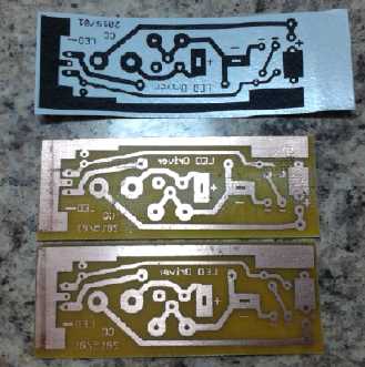 Next was the driver circuit. It was mentioned to me that
one can buy LED constant current drivers for a low cost. So why make
them? There's more to it than that. Mine have a power switch, a 12V
power adapter jack socket and a 12V CAT plug (use either), and a fuse
in a socket, and they mount by soldering the board to the first
heatsink sheet in the light, which carries off the heat and holds the
switch, fuse and connectors accessible from the outside on the side of
the light. The actual LED driver is only part of the whole assembly - a
half dozen cheap components, and a board for the above named components
would still be required.
Next was the driver circuit. It was mentioned to me that
one can buy LED constant current drivers for a low cost. So why make
them? There's more to it than that. Mine have a power switch, a 12V
power adapter jack socket and a 12V CAT plug (use either), and a fuse
in a socket, and they mount by soldering the board to the first
heatsink sheet in the light, which carries off the heat and holds the
switch, fuse and connectors accessible from the outside on the side of
the light. The actual LED driver is only part of the whole assembly - a
half dozen cheap components, and a board for the above named components
would still be required.
(And I've only recently found latching pushbuttons for
power switches (also some 90° alternative switches) that put the
switch where it ought to be, on the side instead of inside the light.)
Of course, a switching regulator would be more flexible
about input voltages and above about 13 volts, it would make less heat.
Perhaps because I've "broken in" the new printer now,
there were very few pits in the toner in the PCB artwork. It
transferred to the board well when "laminated" - actually two boards at
once, which I cut apart later. I etched it (with some new ferric
chloride - and probably much thinner copper cladding on the board) in
less than 10 minutes, and the boards came out looking very good - near
perfect except for some pitting where there had been an existing deep
scratch, almost a crease, in the copper. In fact it's probably about
the best result I've had doing my own boards since graduating BCIT in
19... well, never mind.
Trying out the "toner reactive foil", first a
small piece
laminated onto
paper, and then onto the "final" PCB.
Later I found a missing piece of a trace on one board, the
holes for the switch had the wrong spacing for the new pushswitch pins,
and that they also had two 'extra' body mounting tabs besides the pins.
Sigh, that meant another revision already! As with so many parts, I had
to create the pushswitch design in the parts 'library'.
Finally I realized that I should have printed the board
mirror image. At this point, the afternoon of the 25th, I decided I'd
better do another board. I made it, and again it turned out really
well. I tried the "toner reactive foil" and it probably eliminated any
pitting that might have developed. But instead it tied together a
couple of very close traces - but just in the lettering. I drilled the
holes and soldered on the components. I discovered that, having printed
the board mirror image, I had designed the switch part 'library' mirror
image to the actual hole positions. Finally I tried the light but it
didn't come on. Oh, no, even with everything done nicely, it needed
troubleshooting already? It was supper time and I left it, until the
next afternoon. Then I
realized I hadn't installed the last wire, from the circuit board
across the copper sheet heatsinks to the far end of the light -- the
same wire I forgot last time. With that soldered on, the light worked
great.
The switch was too close to the edge, up against the
plastic case, so I did yet another small redesign of the board.
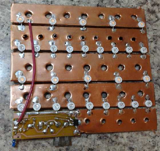 The underside of the light - Violet & Red
LED emitters soldered onto thin copper heatsink sheets.
The underside of the light - Violet & Red
LED emitters soldered onto thin copper heatsink sheets.
The end heatsink does the regulator transistor.
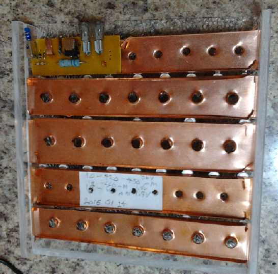
The top side, in the case.
Awg: The new latching power pushswitch is too close to the edge. (Also
crooked.)
Maybe I'll have the next one just right and I'll glue the end onto the
case!
I seem to be spending a ridiculous amount of time to do
each little light! Not counting the delay from the missing wire, this
one was two days instead of the two hours I visualize. I'm not sure
anybody would want to pay for lights at the price I'll have to charge
if I can't get things decently organized for reasonably rapid
production. Of course, I can have PC boards done cheaply in China...
once I'm sure they're designed just how I want them! Or I can probably
make boards a half dozen or more at a time myself, since the PCB Fab in
a Box seems to be working well.
Electricity Generating
Lambda Ray Collector Stuff
Here I wish to compare and
contrast things said about 'free radiant energy' insofar as it's been
identified and described by those involved in energy generation with
things said by the space science community about so-called "very
high energy gamma rays" which I believe are differing descriptions of
the same things, and which I call "lambda rays" as they are actually
far removed from the usual "gamma ray" spectral range.
Note that the highly energetic short rays in question are
in the range of perhaps hundreds of GeV.s or even unit TeV.s, to at
least 10 TeV and probably beyond - topping out at at least over an
order of magnitude higher than the 300 GeV energies the Fermi
Gamma-ray Space Telescope and GLAST [Gamma-ray Large
Area Space Telescope] are designed to detect, and perhaps even 2 or
3 orders of magnitude.
First, from space exploration or astronomical science sources:
The GBM (Gamma Ray Burst Monitor) and the LAT (Large Area Telescope)
will work in tandem to attack the problem of GRBs (Gamma Ray Bursts).
If the GBM picks up an interesting GRB in a part of the sky that is not
in the LAT's field of view at that moment, the spacecraft will slew
autonomously so the LAT can study the burst in more detail. The GBM
will pick up X rays and gamma rays with energies ranging from 8 keV to
30 MeV. The LAT can pick up gamma rays ranging from 20 MeV to 300 GeV.
Former GBM Co-principal Investigator Giselher Lichti of the Max Planck
Institute for Extraterrestrial Physics, which built the GBM detectors,
notes that the GBM and the LAT together cover an energy range extending
from about 10 keV to 300 GeV. "That's seven orders of magnitude in
energy coverage for GRBs," he notes. "That exceeds the energy range
covered by Swift enormously, thus yielding a wealth of new information
about GRBs." The seven orders of magnitude in energy corresponds to 23
octaves on the musical scale, or the equivalent of four full-size piano
keyboards side by side.
The LAT's high-energy coverage will give astronomers
precious insight into an energy realm that so far has been poorly
studied. The Compton Gamma-ray Observatory's Energetic Gamma-Ray
Experiment Telescope (EGRET) instrument detected a handful of extremely
high-energy
gamma
rays
from
a
few
GRBs.
These
photons
did
not
seem
to
behave
the
same
way
as
those detected at lower energies by the
spacecraft's BATSE instrument. Strangely, one of the highest-energy
gamma rays arrived at EGRET 90 minutes later than lower-energy gamma
rays arrived at BATSE. What causes this delayed emission? GLAST's
observations may tell the tale. "We don't understand the
very-high-energy range very well; it's bizarre," says GLAST Project
Scientist Steve Ritz of NASA Goddard. "That energy range will tell us
about the GRB's central engine, so the LAT and the GBM together may be
able to tell us how GRBs actually work."
Note the above remarks I put in bold: that the shorter
wavelength, higher energy photons - lambda rays - have different
behavior than longer wavelength, lower energy gamma rays. This is
why they need their own name. While the focus above is on studying
gamma ray bursts, the high energy rays don't all originate in the
bursts.
Then, here is what I believe to be the same phenomenon, as
described, in a rambling fashion, in some "free energy"
literature:
To understand how the unit operates, it is first necessary to
briefly describe the nature of this energy source.
Research and experimentation have established that this energy is
one that pervades the known universe and is constantly flowing
through
the Earth itself. It has been found to be quite dense, with enough
power to light an American city of around 50,000 persons for a year.
Because of its origins and immense power potential, this energy has
been called “vacuum,” “cosmic,” “radiant,” or “zero-point” energy. Dr.
Nikola Tesla, the discoverer of the electric age, may have used this
energy to create his most fantastic invention-the “Magnifying
Transmitter.”
At the beginning of this [20th] century, Tesla was able to send
electrical
energy through the earth without the use of wires. In a test
transmission, he sent electricity to a receiver located twenty six
miles away where a bank of 200 fifty watt light bulbs lit for as long
as the transmitter operated. This demonstration convinced Tesla that he
had learned the principles of operating the Earth as a gigantic
resonating cavity. This resonating cavity had the ability to conduct
not only electricity, but also radio waves and any other type of
electromagnetic wave. However, the key part was the ability of the
transmitter to magnify electromagnetic waves. Also, the device had the
ability to transmit this energy at a frequency comparable to the
Schuman cycle (6 to 13 hertz). This fact indicated that Tesla had
stumbled onto a new form of energy directly convertible into
electricity. Evidence of this discovery can be seen in two actions
taken by Tesla after the success of the Colorado Springs Experiments.
In July 1902, he wrote a letter to Robert Underwood Johnson in which
there was mentioned a discovery of a new unknown energy that could be
used to create “fuel-less motors.” At the same time, Tesla was
demonstrating these devices to other friends and refusing to apply for
U.S. patents.
Recently researchers have discovered a number of interesting facts
about Tesla’s energy. First the energy traveled through the universe as
a spiraling stationary wave or corkscrew. Second the energy can be
conducted by electrical instruments (wires, etc.) composed of metals
that are also excellent conductors of electricity (gold, silver,
copper, etc). Strangely, those conductors that have no known natural
magnetic property such as aluminum can not be used to collect these
energies, but only to disperse them. Finally the energy in its
corkscrew fashion carried itself around the outside of a wire and
not
through it as was the case with conventional electricity. Hence, it
will be necessary to construct motors that are wound slightly
differently in order to make the best use of this energy source.
However it will be possible to inter-phase this energy into the modern
electrical world and gradually “phase in” the new system.
The idea of a spiral or
corkscrew wave is probably indicative of very high frequencies, which
tend to travel along the skin of wires ("skin effect") rather than
through the copper as a whole. (It also seems to interact better with
good electrical conductors that are also heavier elements like gold
than with light ones such as aluminum. I don't know of any special
magnetic or
electrical properties of the column 1-B elements mentioned above that
aluminum doesn't share.)
The chief difference I presume to be
that the space scientists have a much clearer idea of what the rays are
and their frequencies and individual photonic energies, but apparently
so
far without realizing their tremendous potential as an actual energy
source, while the free energy enthusiasts have only a vague and
uncertain idea that they are extremely high frequency rays, but
understand that the density of these rays is high and so they can
provide a lot of energy from a small collector unit if effectively
harnessed.
The "5000 patents
classified as secret by the US patent office" (see "In Passing" above),
along with numerous other indications such as the Brazilian inventor
pair with 'earth electron converter' free energy device patents and
even someone appearing on Dragon's Den with a 'free energy device' may
well indicate that success in collecting lambda rays and converting
them to electricity - along with suppression of the knowledge and their
techniques - is
much more common than we're led to believe.
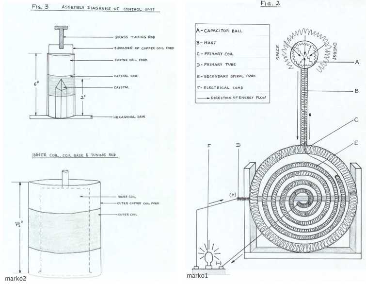 A well-circulated diagram of some "space energy
receiver" or "lambda ray collector" (as I would describe it) components.
A well-circulated diagram of some "space energy
receiver" or "lambda ray collector" (as I would describe it) components.
Unfortunately the details are frustratingly obscure and no proper
schematics or photos are available.
Electricity
Storage
(Sorry, No Report on Turquoise Battery Project)
A Lead-acid battery restore story
I haven't been doing very well at renewing PbPb batteries
for the Mazda, but someone bought some sodium sulfate from me, and he
bought a pulse charger as I recommended. He said he filled his battery
with distilled water and
the sodium sulfate and told me that the renewal had brought his RV
battery back from the dead, and it will again run lights at night, etc.
(And the dealer told him he had brought many batteries back to
life with the pulse charging.)
Whether or not it would give full range in an electric car, it
sounds like it worked well for him.
New NiMH
Battery Pack Blow-up: Cordless Power Drill Battery
I thought I had got rid of
all my NiMH batteries that only
had plastic-covered cells. I forgot a couple of small ones: those for
my electric drill. These were in fact the very first ones I made, quite
a few years back, when someone gave me a 9.6 volt Black &
Decker battery operated drill with dead NiCd batteries, and no charger.
When I got it in 2008(?), I thought of the idea of simply
replacing the 8 dead
NiCd.s with 8 NiMH "AA" cells. I bought some locally. It worked like a
charm, tho it wasn't quite as powerful. I knew it wouldn't be.
Later
when I found all-battery.com Tenergy batteries on line in 2010, they
had "high rate" AA cells, and I replaced the dead NiCd.s in the drill's
other battery pack with 8 of those. That worked even better, with the
drill probably around as strong as originally. I've used the
drill
for most everything for some years now, always marvelling that I went
so many years without a cordless drill. But long-life NiMH batteries
make a tremendous difference over the ever troublesome NiCd.s, and they
only became available about 1997.
Before cordless tools, people used to nail boards together
to construct wooden things. Now one uses construction screws, put in
with a cordless drill or driver. It's a good advance, especially if
the item needs to be disassembled later. It's simply unscrewed, zip!,
and there are no bent nails or anything left in the boards, which thus
can often be used again for
some new construction. It's also great for garden frames that are used
for a season and changed the next year.
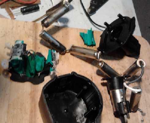 On the 15th I connected the "high rate" battery to the lab
power supply to charge it (after doing some drilling for the Unipolar
Motor project), but it seems I thoughtlessly set the voltage to 11.4
volts
instead of 11.2 volts. (Should have been 1.40 volts/cell * 8 cells =
11.20 volts.) And as it happened, I didn't go back into the lab until
the next day. When the voltage is too high, the cells continue to draw
current after they're charged. Being dry cells they can't vent liquid
and they just get warm and eventually hot.
On the 15th I connected the "high rate" battery to the lab
power supply to charge it (after doing some drilling for the Unipolar
Motor project), but it seems I thoughtlessly set the voltage to 11.4
volts
instead of 11.2 volts. (Should have been 1.40 volts/cell * 8 cells =
11.20 volts.) And as it happened, I didn't go back into the lab until
the next day. When the voltage is too high, the cells continue to draw
current after they're charged. Being dry cells they can't vent liquid
and they just get warm and eventually hot.
The failure followed the usual pattern: The cells got hot,
their plastic covers melted, and then the outer metal cans of two cells
touched each other, shorting them together. Then the heat really
starts, and soon all the cases have melted, and shorted together, and
they swell up and explode or vent their liquid.
After I pulled it
apart, I washed my hands, and I was glad I did - once rinsing them I
realized my fingers were coated with slimy potassium hydroxide from the
burst cells. It's nasty stuff, and once it had soaked in it would have
done some damage to my skin and tissues over the course of an hour or
two. (And in the eyes it will blind. This is one reason I created my
two battery chemistries using potassium chloride electrolyte instead.
This edible salt actually enabled the new chemistries, neither of which
seems to work in potassium hydroxide... altho I'm not entirely
convinced Ni-Mn couldn't be coerced to do so with sufficient trace
additives if the cells are refrigerated.)
Considering that power tool batteries come with
cardboard-lined cells, Tenergy looks pretty irresponsible to be selling
cells intended for battery packs without melt-proof liners. Of course,
after
about 4 blown packs now, I'm finally wise to this trick, and I'll wrap
tarpaper or cardboard around the replacement set. (I used masking tape.
I may even do
pre-emptive wrappings on the remaining drill battery.
There's a lot of empty space with the AA cells, and it's
much lighter
than the original NiCd.s. But it has as much or
more total energy - 2.5 amp-hours for regular AA or 1.8 AH for the high
rate AA cells, versus maybe 1.5(?) AH with the original NiCd cells.
Now, the last
question I'd been idly wondering about for quite some time (and now
checked out) is whether two sets of 8 AA cells will fit into the
battery case. If so, doubling up regular AA cells will give the high
current capacity for 'full power' and 5 AH of energy. That
would do a lot of work on one charge! If two
sets won't fit... I have some more of the high-rate 1.8 AH AA cells to
duplicate the excellent performance I've been getting. Now, if only I
had a mind that didn't space out now and then when hooking them up to
charge... or maybe a proper charger.
When I went to make the battery (20th) I found I just
couldn't fit 18 cells in the case. It was never made for AA size. 16
cells with a small gap under the lid was tops. So I decided to put in 9
high rate cells. While I was doing so, my brain finally sprung into
action - sort of: Duh, it's only 8 cells for 9 volts, not 9! (Actually,
"9 volt" power tools with alkaline batteries are nominal 9.6 volts, and
charge as stated to 11.2 volts. ...be that as it may!) Only after I had
it
all finished did I realize, Hey!, I could have fit 16 cells and
had 2 in parallel per position after all, which would have given a good
high discharge rate and 5 amp-hours instead of 1.8. (Or, 5AH *
9.6V = 48WH instead of 17WH.) I could do the other battery, which has 8
ordinary cells at present, but it seems like a lot of bother to fix
something that's working. So the experimental opportunity is gone for
now.
The new AA battery pack for the drill, and part
of a
commercial D cell (e-bike) battery pack, showing the
paper wrapping of the cells inside the plastic, and
how the paper extends even over the top of the cell,
to prevent the spot welded connection tab from
shorting the center terminal to the outer case.
(Bottom right - some of the broken off "solder tabs".)
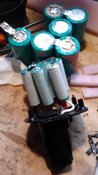 I
started by wrapping each cell with masking tape (very
convenient, and which I *believe* has paper in it and won't liquify
like hot plastic). The tape was the same width as the battery height.
These high rate batteries had "solder tabs" spot welded on. Both
pointed the same direction, which was awkward. Then I realized that the
tabs had no better insulation than the cells: just plastic that could
melt. Furthermore, the high rate cells were "flat top"
instead of regular "button top". The tab plastic and case plastic could
melt and easily short the "+" tab to the "-" case on the same cell. So
I bent all the solder tabs back and forth and broke them off. So much
for spot welded solder tabs! I will restate: In decades of occasionaly
doing so and almost a thousand batteries since 2010, I have never, ever
had any known problem resulting from soldering wires directly onto dry
cells.
I
started by wrapping each cell with masking tape (very
convenient, and which I *believe* has paper in it and won't liquify
like hot plastic). The tape was the same width as the battery height.
These high rate batteries had "solder tabs" spot welded on. Both
pointed the same direction, which was awkward. Then I realized that the
tabs had no better insulation than the cells: just plastic that could
melt. Furthermore, the high rate cells were "flat top"
instead of regular "button top". The tab plastic and case plastic could
melt and easily short the "+" tab to the "-" case on the same cell. So
I bent all the solder tabs back and forth and broke them off. So much
for spot welded solder tabs! I will restate: In decades of occasionaly
doing so and almost a thousand batteries since 2010, I have never, ever
had any known problem resulting from soldering wires directly onto dry
cells.
On commercially made battery packs, the cardboard wrapping
on each cell extends up over the top of the can and is folded inward to
protect the tab from the top of the can. And the tabs are welded in
whichever direction they need to go - which is never with both
pointing the same way (which would short two cells out).
These are not just "academic" safety considerations. This
is the 3rd or 4th dry cell battery pack I've made that has burned up by
being overcharged for one reason or another, along with hundreds of
dollars of NiMH cells and the potential, especially with the larger
ones, of causing injury, chemical burns (nasty KOH electrolyte) or a
fire. So of course I never make them without the paper wrappings and
insulated wire jumpers any more. But there are, evidently, a couple of
earlier made potential "time bombs" still around.
When I put the new battery on charge, I came back an hour
later and saw that the power supply voltage had crept up from 11.2
volts to 11.3. When I turned it back down, current to the battery
dropped from 300mA to 100, and turning it any lower, the current went
to zero and it sat at 11.2 volts since the battery had charged to that.
It seems to me the power supply used to be quite stable, but I've
noticed the voltage go up slightly as it warms up on more than one
occasion recently. Maybe after all it wasn't some mental lapse on my
part that
had it up at 11.4 instead of 11.2!
Lithium-Iron
phosphate
& Nickel-Metal hydride Battery Life
I've been testing lithium-ion and NiMH batteries in the
Mazda, wondering about their relative life spans. One keeps hearing
about the amazingly long life of lithiums, with claims of several
thousands of cycles. But how has this been tested, so quickly after
they started making them? Have they in fact been tested, or is it
merely a theoretical value? I heard once that they aren't lasting as
long in
laptop computers as NiMH.
Then on the all-battery.com website, the NiMH dry cells
used to
claim 1000 recharges before dropping to 80% of their original capacity.
Then one day, I noticed that was reduced to 500! That's hardly a minor
adjustment, and it indicates that the original figure wasn't well
tested - it may have been theoretical.
Of course, the figures for lead-acid batteries - usually
somewhere over 100 cycles (to 60% discharge) but even over 600 for
'golf cart' batteries (which BTW contain sodium sulfate), are only
attained
under ideal conditions which seem to be more theoretical than real.
Now I've found a web site where someone has purchased and
has been tracking the capacity of their lithium-iron phosphate
batteries for 3-1/2 years in use in an RV for lights, etc. They get
charged during the day by solar PV panels. This isn't the sudden high
currents of EV.s but definite steady cycling.
www.technomadia.com/2015/02/living-the-lithium-lifestyle-3-5-year-lithium-rv-battery-update/
The batteries came rated
for 5000 cycles. 3-1/2 years represents around 1250 days of use, hence
1250
cycles, 1/4 of 5000. They are down to 75% of the rated capacity, in
well
under the claimed cycle life. Ambient temperature is a concern, as are
charging conditions, and they note that others have had varying
results, some similar and some considerably better, and that
constructions are said to
have been improved since their purchase in 2011. But like lead-acid,
the 5000 cycles rating seems to be under ideal conditions that are
unlikely to be met in real life. For those concerned with lithium
battery performance and life, the article has tips worth reading.
My EV use experience is still under 2 years. The older
NiMH batteries, almost 2 years now, seem to have reduced current drive
more than reduced amp-hours capacity, dropping to lower voltages under
load and then springing back to near the same voltage as the newer ones
after
stopping. They're probably getting towards the 500 cycle mark. The 200
amps I try to stay under (preferably well under) is after all asking 20
amps from each D cell. When the current drive is only just adequate to
start with, this is a factor. I think ~150 amp-hours capacity or more
would continue performing well for a lot longer and better than the 100
amp-hours I'm using now, and give substantially more than 50% extra
driving
range. I'm also pretty sure that the 30AH NiMH D cell starter battery
in the Tercel doesn't crank the engine over as fast as it did when new,
four
years ago.
The lithium-ion cells, after maybe a year, don't seem to
be at their original performance levels either, the voltages dropping
lower under load. Again they'd probably benefit from being 150AH
instead of 100.
This is all testing under some actual use conditions
rather than just ideal or theoretical.
Now, if I could just get the 'forever' cycle life
nickel-nickel cells (probably highest current rate and could easily be
dry cells) and nickel-manganese cells (highest voltage - should
probably be flooded cells only) working to some practical level, all
this (at least ideally and theoretically) *should* become academic.
Maybe I'll try coating the edges and back face of the 'graphite foil'
current
collectors with epoxy - or even wax - to at least reduce the wicking of
liquid up to the terminals.
http://www.TurquoiseEnergy.com
Victoria BC Canada