Turquoise
Energy Ltd. News #85
February 2015 (posted March 2nd)
Victoria BC
by Craig Carmichael
www.TurquoiseEnergy.com
= www.ElectricCaik.com
= www.ElectricHubcap.com
= www.ElectricWeel.com
Month In Brief
(Project Summaries)
- unipolar motor & controller - variable reluctance motor -
magnetic shielding material? - aquaponics & LED lighting
- Giant Electric Weel motor/generator & floating hydro power
In Passing
(Miscellaneous topics, editorial comments & opinionated rants)
- Improving Systems of Governance: Election CampaynCentral.com
web
page - Airless World Life in the Solar System: alien plant seed
found...
vegetation on Ceres too!?! - Offensive Cartoon - Precious metals:
Silver investing video
series; the
investor fleecing
game; Operation Chokepoint - Feedback on Patent Suppression of energy
inventions - NO MORE WARS!
Electric Transport - Electric
Hubcap Motor Systems
* Unipolar Motor & Controller
* Turquoise Bipolar BLDC Motor Controller Problem Identified?
* RX7 New Battery Notes
* Electric Weel Generator/Motor
Other "Green"
Electric Equipment Projects
* Aquaponics & LED Grow Lighting
Electricity Generation (No reports)
Electricity Storage - Turquoise Battery
Project (NiMn, NiNi), etc.
* Leonardo Elionix's Manganese-air cell
No Project Reports on: Variable
Torque Converter Transmission, Turquoise
Battery Project, Magnet motor,
Lambda ray collector, evacuated tube heat radiators, CNC
gardening/farming machine.
February in Brief
After more time setting up finances and then finishing the January
newsletter on the 5th, on the 6th I installed the new 11th battery in
the
Mazda RX7 EV, bringing it up to 140 nominal volts. On the 9th, quite a
warm day, I drove 3.4 miles using just 252 WH per mile (1.8 AH/mile
@140v) instead of about 300 WH or more (2.3+ AH/mile @128v). That's
over 15% less energy per distance. Theoretically it should be the same.
Does the 144 volt motor become less efficient at
lower voltages, or was it "luck" with traffic, traffic lights and the
route? I drove it quite a bit towards the end of the month,
knowing that if I had to go two or three extra miles it now wouldn't
poop
out on me. Mostly with traffic and shopping stops and starts it used
around 280 WH/mile, but occasionally on smooth trips, catching most of
the traffic lights green, it would do notably better. I can see that on
level
ground at low constant speeds (under 50Km/hr) in warm weather it would
do much better, but that's not the driving conditions around here.
On adding another 10 amp-hour set of dry cells to the
weakest NiMH battery (in PVC pipes) to make it 110AH, I found it still
loses the most voltage under load, but after stopping its voltage would
now recover to above its "twin". It seems as they age the NiMH dry
cells lose current drive more than storage capacity. This is probably
from gradual escape of the tiny amount of liquid in the electrolyte -
the dry cells actually drying out. The big flooded NiMH cells that
Chevron won't let anyone make wouldn't have that problem.
 I
got back to the unipolar motor on the 6th. I fixed the
too-large bolt holes by using waxed threaded rods to shape the holes
and keep them
open,
and using them to push in some PP cloth and epoxy filler. It's great to
be able to add material
back into the motor body as well as remove it! When the epoxy was set I
unscrewed the
rods and screwed in the nylon bolts to fasten the rotor end cover on.
The next day I added 5 bolts to the stator side. (The 6th one couldn't
be placed because the heavy wires inside were in the way.) That
finished the
motor!
I
got back to the unipolar motor on the 6th. I fixed the
too-large bolt holes by using waxed threaded rods to shape the holes
and keep them
open,
and using them to push in some PP cloth and epoxy filler. It's great to
be able to add material
back into the motor body as well as remove it! When the epoxy was set I
unscrewed the
rods and screwed in the nylon bolts to fasten the rotor end cover on.
The next day I added 5 bolts to the stator side. (The 6th one couldn't
be placed because the heavy wires inside were in the way.) That
finished the
motor!
But tests on the optical rotor position sensors indicated
they
might cause trouble. Everything fit well and it turned freely, but with
the wide gap for the thick plastic slotted drum, the phototransistors
were too far from the LED.s and so weren't driven anything like as hard
as they should be.
 I asked on the
motor controller e-mail group (osmc@yahoogroups.com) if there was any
other type of motor that
could run unipolar, with no H-bridges in the controller - fully
expecting the
answer would be "no". But some smartass came up with one: the "switched
reluctance" motor. The name just sounded so weird I'd never looked it
up before. The rotor
has no magnets, just iron.
I asked on the
motor controller e-mail group (osmc@yahoogroups.com) if there was any
other type of motor that
could run unipolar, with no H-bridges in the controller - fully
expecting the
answer would be "no". But some smartass came up with one: the "switched
reluctance" motor. The name just sounded so weird I'd never looked it
up before. The rotor
has no magnets, just iron.
Because of the shape of the rotor, if any
coil is on, a long axis ("salient pole") will try to align with that
coil, and running
the motor can be done exactly like my own unipolar system, with the
very same controller I've just made. The inductance of the coils varies
with the rotor position, and this is said to be a control challenge.
But the CRM type modulation I use in place of PWM adjusts cycle by
cycle anyway: the value of the inductance is accommodated by the
variable frequency cycle. The
only
difference in the motor from my unipolar is the rotor, which for axial
flux might simply
be a silicon steel
plate with cut-outs. (It should apparently be soft magnetic material:
Silicon steel, Mu-metal, the same iron powder toroids I use for the
coil cores,
or...?) Surely it wouldn't
take much to convert any of my motors to switched reluctance type. The main questions will be about torque and
efficiency, but I suspect they wouldn't be much different.
As the month wore on, I
became more and more enamored with the
idea: a rotor without magnets to fly off could tolerate much higher
RPM.s safely, and the labor and cost for the rotor would drop - the
labor to
nothing if a simple steel plate (with a correctly patterned outer edge)
was waterjet cut. It sounds like a
better, cheaper motor!
With the motor together I wanted next to start on the
motor controller, but I
became busy with other things.
 On the 13th
the customer for the big Electric Weel called,
at last wanting to finish the Weel. We must be headed for the 2 year
point. His floating hydroelectricity project seems to be running on and
on
like many of
my projects. That's just as well for me since I've had so little time
to spare for the Weel. But it sounds like the vessel and mechanism is
nearing completion.
On the 13th
the customer for the big Electric Weel called,
at last wanting to finish the Weel. We must be headed for the 2 year
point. His floating hydroelectricity project seems to be running on and
on
like many of
my projects. That's just as well for me since I've had so little time
to spare for the Weel. But it sounds like the vessel and mechanism is
nearing completion.
He came over and drilled the holes and we assembled the
stator side. We decided to use #10-24 stainless steel bolts (AKA
'machine screws') on the inside area (which is farther from the
magnets) and the rim area, using 1/4" nylon bolts only for the coil
centers where metal would be magnetically heated the most.
The unit
except the rotor weighed only 58 pounds! With the
lexan rotor (and 32 magnets), hopefully it'll be around 80 pounds
complete. I think a
low
RPM unit probably good for almost 20KW continuous would
usually want a hoist to lift it.
When I wrote the G-Code for routing out the lexan rotor I
came up with a new idea. The 26" O.D. steel ring around the outside
holds the magnets, and I sized the lexan the exact inside diameter of
that ring. Thus it would fit flush with the metal. The slots for the
magnet strapping would be CNC router cut through the lexan (much easier
than through steel!), and the epoxied straps would wrap around both
lexan and steel (and the magnets - plus maybe some extra straps) to
bond everything together. The strong outer steel ring should guarantee
a strong rotor good for higher RPM.s. (Which means only maybe 750
RPM for such a huge diameter machine.)
A couple of days later I wrote G-Code for, and made, 3
lexan reinforcing rings, to be glued to the main ring. With two keys on
opposite sides of the shaft, running across an inch of lexan, I hope
for the sort of strength that a thinner piece of metal with one key
would provide.
It occurs to me that I myself have two skinny 12',
lightweight, foam sandwich 'catamaran' floats that I made long ago as
part of a trimaran boat idea. (The center hull is long gone.)
Unfortunately they're rather small to use as a catamaran (tho my
brother and I once put a sail on it and took it out on a lake). With
these I could probably make a small version of a floating hydro power
plant myself. But I don't have river or stream front any more than I
have ocean front for doing wave power, so I wouldn't know where to
install it and would have a hard time deriving any benefit myself.
I met someone who was connected with someone reputed to
have created some special magnetic shielding material, supposedly
useful for
making a magnet motor. This was interesting because the keys to making
a magnet motor work are getting intense flux at the right point, and
(presumably) creating an asymmetry of strength interaction as seen by
the rotor between the forward propulsion and the reverse propulsion
magnetic fields. Both of these would seem to be strongly influenced by
magnetic shielding factors.
There was a video clip with a stator and a rotor magnet,
showing that the rotor would turn strongly in one direction as it
passed the stator magnet, with seemingly very little reverse force at
any point in the rotation. But it didn't do a full circle. The
construction was amateur and the magnets were only held down with cable
ties, so they shifted around as they crossed paths. The originator
doesn't want to disclose the material without a non-disclosure
agreement... and he's also in hospital. (Hmm... He had a heart attack
returning from a trip to promote a material for free energy. Something
untoward happens to yet another free energy inventor... is that
suspicious, or just a coincidence?) I asked if they knew what the
material was, thinking of one elderly person who had made something
unusual and maybe useful which
he demonstrated in a video, and then died without revealing his
secret. "More or less." Perhaps if it turns out to be anything more
special than Mu-metal, I'll be told some day. Certainly there are also
interesting materials like bismuth that are diamagnetic and might
deflect a magnetic field. Bismuth will in fact float over top of
supermagnets.
The Weel rotor, with
outer steel
ring, lexan center with slots for the magnet
straps, and reinforcing pieces for the center area and shaft connection.
 It seemed I
was diverted every day by something or other
more pressing than the major energy projects, aside from the sudden
productive day working on the Weel - which was itself that day's
diversion from the unipolar motor. By the 16th, I felt like I was just
treading water. After spending the day with my two brothers (one of
whom had just arrived from Toronto for a visit and the other who was in
hospital), and desperate to get something underway, I started
shortly before 10PM to cut the lexan rotor for the big Weel motor and
worked into the wee hours. I got it done. The next day I cut off the
welds holding the metal outer ring for the
magnets from the previous heavy steel rotor piece, ground off the weld
crap, and sanded down the lexan to fit inside that ring by some
millimeters. (It was somehow a bit too big by in spite of careful
measurements and
calculations.) On the 18th or so I cut some smaller diameter pieces to
reinforce the center axle area, to be glued to the main rotor piece.
It seemed I
was diverted every day by something or other
more pressing than the major energy projects, aside from the sudden
productive day working on the Weel - which was itself that day's
diversion from the unipolar motor. By the 16th, I felt like I was just
treading water. After spending the day with my two brothers (one of
whom had just arrived from Toronto for a visit and the other who was in
hospital), and desperate to get something underway, I started
shortly before 10PM to cut the lexan rotor for the big Weel motor and
worked into the wee hours. I got it done. The next day I cut off the
welds holding the metal outer ring for the
magnets from the previous heavy steel rotor piece, ground off the weld
crap, and sanded down the lexan to fit inside that ring by some
millimeters. (It was somehow a bit too big by in spite of careful
measurements and
calculations.) On the 18th or so I cut some smaller diameter pieces to
reinforce the center axle area, to be glued to the main rotor piece.
After that, it needs some sort of jig for placing the 32
magnets in exact positions on the rotor ring. Then the rotor can be
made and installed, and the first Electric Weel will (at last!) be
complete.
With the big cutback and year late refund for 2013 from
Canada Revenue (still not received), I spent a lot of time in February
on "financial affairs" of one description or another. I traded last
summer's high rate house mortgage for a CHIP reverse mortgage, for
those over 55, where they assume you'll die or sell the house in a
foreseeable future, and that the dollar value of the home will rise
over time. In this mortgage, a value up to somewhat less than 1/2 the
home's value may be borrowed (depending on age), and the interest each
month is added to the amount owed instead of being paid off monthly.
Indeed, one can even get money monthly until the limit is reached, and
I'm taking a modest amount to help stay afloat. CHIP never forecloses,
foreseeing getting all their money plus the interest due 99% of the
time, perhaps taking a small loss of interest very occasionally if an
owner should live for a very long time and values fail to rise.
Unipolar Motor & Controller testing.
(Bottom of
motor, on table within reach, is just visible at top)
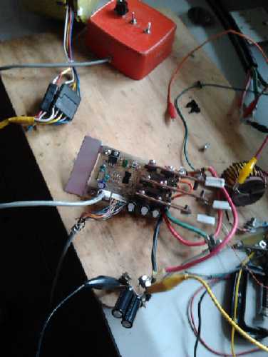 From the 20th on in bits of time I found, I put the unipolar motor and
controller together and began to troubleshoot and test it. I wired the
controller out of its box so I could measure voltages and make any
needed changes.
From the 20th on in bits of time I found, I put the unipolar motor and
controller together and began to troubleshoot and test it. I wired the
controller out of its box so I could measure voltages and make any
needed changes.
There was a problem with the optical interrupter system.
One phototransistor wasn't matched to its LED and (as I had feared) I
had to take the motor apart and replace the pair, with new
optical parts received since the original assembly.
There were problems with the modulation system, which had
to combine CRM and PWM owing to the overcurrent signal not being
available on the MC33035 motor controller chip. I made
some changes, but I'm still not satisfied.
On March 1st (call it February 29th!) it finally ran. But
most of the 80 or so
watts seemed to be going into heating up the power transistors. I had
blown 3 before it was going, and they were still getting hot. This
behavior might (perhaps) be explained if the coils are attracting the
magnets
instead of repelling them, so the polarity needs to be verified.
In Passing
(Miscellaneous topics, editorial comments & opinionated rants)
Improving Systems of Governance: CampaynCentral.com
web
page
I wrote a draft letter for the newspapers about the civic
e-mail group list which I hope will become the main vehicle of
communication for civic governance discussions. In it I gave a URL to
go to "for more information". I couldn't think of much that I hadn't
already put in the letter, but I thought I'd better at least write up a
web page and put it at the URL given so people wouldn't get an error
trying to look it up. I copied the letter to the page.
Then I started to write up the web page, just a couple of
sentences saying there was no additional info so far beyond what was
said in the letter... and what I
think is a brilliant idea came to me as I wrote: "Election
Campaign Central". (That seemed too long and I made the actual
title "CampaynCentral.com".
CampaignCentral.com and most anything with the word "campaign" was
taken. Some appeared to be being held for ransom.)
Please note that the page/site doesn't exist yet at
this writing. I've only had time so far to reserve the domain name, so
you'll get an error if you try to go there.
CampaynCentral.com would be a
web site where most of the promotion for any election would be
done -
all at no cost. At first I was only thinking of civic elections, but it
should work just as well for state/province and national elections...
anywhere! It
would soon become known as the place to find information about
all
elections. As a starting point, I would divide the page into three
sections.
First, candidates for office would put up a main
introductory
video and or write-up. They would be free as to content and length. For
example they could introduce themself and state their qualifications,
and their goals and ideas of what they would like to do if elected.
The next section would be a place for public questions and
comments. In the third section the candidates (or in larger
jurisdictions perhaps their campaign representatives) would be able to
respond
by video or in text to any of the topics raised by the public that they
care to address.
The mainstream media is almost 100% delinquent in putting this sort of
essential information across to the public, so candidates become known
only in proportion to how much money they have behind them, and
elections have become corrupt, with the whole agenda controlled by the
ultra-rich. This web site should go a long way to removing the dollar
sign from election success prospects. Having the ultra-rich buy
candidates and buy elections should become impractical. Voter apathy
has become inevitable as people see how they vote usually makes no
difference to anything.
Once one candidate for office puts up a promotional video,
then, given a certain minimum amount of publicity for the site, the
other candidates wouldn't dare ignore it. Anyone not bothering to do
their video or other introduction would stand out as being an
"absentee" candidate, someone not really serious
about winning votes and the office. This will ensure universal,
'permanent' adoption of the site once it's been used in an election or
two and people are familiar with it. Promotions elsewhere and by
monetary means should become much less effective.
A follow-up idea is to get the world's open source
programming community behind these projects instead of trying to do
everything myself. As readers of this newsletter know, I already have
projects to from here to yin-yang. Someone suggested I could do it all
with "JOOMLA" web page environment, which I haven't had a chance to
look at yet. But that doesn't fit in very well with "offloading" the
project!
The descriptive page for more information is here:
www.saers.com/recorder/craig/cities.html
Airless World Life in the Solar System
The airless worlds orbiting Jupiter and Saturn seem so
cold and distant and well... airless... to us on this planet that the
mind simply rebels at any thought that anything could possibly live on
them. And when one does think of life on other worlds, one thinks of
animals, or maybe microbes. But plant life, the "forest canopy", is
what will
be observed from space.
Spectral readings in specific locations on various of
these
worlds are described as showing
mainly 'polycyclic aromatic hydrocarbons', with carbon dioxide in a
'stretched' or 'energized' state. And descriptions such as
"fluffy" and "very fluffy" have been derived from analysis of diurnal
temperatures.
It has for some years now been apparent to me that these
things, however impossible it seems, can hardly mean anything but that
there's some sort of strange alien
vegetation growing on the
surface. (Another scientist's skeptical writing about the 'fluffy'
layer actually reinforced the picture. He said (not an exact quote):
'Sunlight would have penetrate the proposed fluffy layer in order to
produce the
results as described.' Thus it sounds more and more like vegetation.)
But how did it spread from world to world?
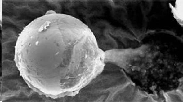 This month two
new findings have hit my eye. The first is
the collection of a what was described as an alien "seed" by a
balloon sent 27 miles above the Earth's surface. It left a crater
in the sample collector, indicating it must have come in from space at
a high rate of speed rather than having a terrestrial origin. (One of
several links:
This month two
new findings have hit my eye. The first is
the collection of a what was described as an alien "seed" by a
balloon sent 27 miles above the Earth's surface. It left a crater
in the sample collector, indicating it must have come in from space at
a high rate of speed rather than having a terrestrial origin. (One of
several links:
http://www.buckingham.ac.uk/research/bcab/news)
The object was "the width of a human hair" and with a hard
"metallic" shell (but organic looking), and what might be a root or
stem coming out of a hole in one side.
My theory
of one technique for spreading of spores or seeds on airless worlds is
that the
plants would shoot them out at high speeds to fall and start to grow
elsewhere. Once such plants got transplanted from Ganymede
(...the likely guess since it's half the size of Mars and has a
magnetic field) to any tiny world, in debris kicked up by meteors,
their ejected seeds would escape the tiny gravities and start flying
all over the solar system. This seed sheds light on the specifics,
entirely in accord
with and reinforcing this theory. That anyone might find it without
going to another world was a
surprise, but the balloon experiment by believers in "panspermia"
was
searching
for
exactly
this
sort
of
thing. What a stunning success!
This follows intriguing findings by others in
recent years of
what appear to be microbes or diatoms, in carbonaceous chondrite
meteors,
which I
believe are composed of soil debris kicked up by larger meteors from
airless worlds that
have this same strange life, somewhat fused into a solid by passage
through Earth's atmosphere as well as heat and pressure from the
original meteor impact that kicked it into space. This same may be what
"fossilizes" the organisms. (Links: http://www.panspermia.org
/hoover.htm and http://www.usaukonline.com/latest-news/8091-second-study-finds-extra-terrestrial-fossils-in-meteor-fragment.html.
One
person, widely quoted, "debunked" the first findings, but a second
thorough university study
concluded the diatoms weren't of terrestrial origin. This too found its
detractors.
Unless my memory
is bad, there have been other meteorites (one or two) previously said
to contain "primitive (non-eukariotic) microbes" from space, but the
Sri Lankan meteor is the only one I seem to be able to find reference
to at the moment.)
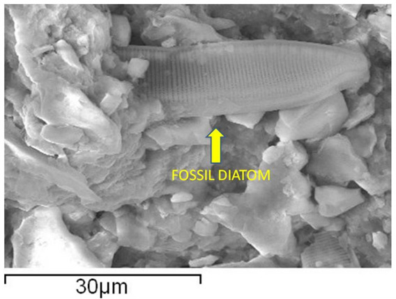 SEM Electron microscopic image of a bit of the
meteor, seemingly a sample of
SEM Electron microscopic image of a bit of the
meteor, seemingly a sample of
"diatomatious earth" with a diatom (algae cell) that looks a lot like
Earthly ones.
 The second item is new "highest rez so far" images of Ceres
from the Dawn
spacecraft. In March 2015 Dawn is to enter orbit around Ceres, the
largest
asteroid orbiting the Sun in resonance with Jupiter. At 915Km
diameter
Ceres is about 2% of the size of Earth's moon (3476Km).
The second item is new "highest rez so far" images of Ceres
from the Dawn
spacecraft. In March 2015 Dawn is to enter orbit around Ceres, the
largest
asteroid orbiting the Sun in resonance with Jupiter. At 915Km
diameter
Ceres is about 2% of the size of Earth's moon (3476Km).
(Note: It's an
almost ubiquitous mistake to compare diameters of worlds as "sizes".
Volume - size - of
a sphere is 1/6 pi D^3, and (3476/915)^3 is a 48
to 1 volume ratio. A baseball may be, say, twice the diameter of a golf
ball, but that's 8 times as large.)
Expecting that Ceres consists primarily of water ice,
scientists anticipated a high albedo with a lot of reflected
light -
like the trailing hemisphere of Saturn's moon Iapetus. Instead,
Ceres is quite dark - like the front
hemisphere
of Iapetus.
Any plants on the trailing hemisphere of Iapetus would be
irradiated by Saturn's deadly ionizing radiation, swept around at high
speed by its magnetic field, so mainly the leading hemisphere can grow
vegetation. Ceres is far from Saturn's or Jupiter's
radiation, but evidently isn't too close to the sun for this type of
life and probably it would have decent soil. Two bright
(ice) craters similar to some bright craters on the front face of
Iapetus visually indicate
compositional similarities. On Iapetus, space
scientists estimated that for there to be so few bright craters, the
world is being resurfaced with the dark fluffy organic material in, at
most,
100,000 years, and more probably in much less time than that.
(Apparently that didn't lead to any thoughts that the fluffy organic
surface might be
composed of living
vegetation.)
Another reason for bright areas is glare ice rather than
good soil. Inner worlds of Saturn and Jupiter (Europa, Rhea, ...) are
tidally churned so that the heavier elements sink to the middle leaving
ice on the whole surface, and various bright ice extrusions are found
around many craters on the outer worlds - since water expands as it
freezes.
I have been idly wondering for some time if some of the
asteroids might be covered
with the same vegetation as Ganymede, Callisto, Iapetus and other
airless worlds of the Jupiter and Saturn systems. I couldn't think of
any good reason why not unless they were too warm. After these images I
am waiting to hear that
the
surface of Iapetus is "fluffy" and that spectral readings are of
polycyclic aromatic hydrocarbons. And that small scale surface features
such as small craters are obscured by the dark material. And I'm
wondering if the Dawn might
actually give us a tantalizing glimpse, or even a good view, of the
plant life canopy as it approaches Ceres in the coming weeks.
(One link is here: http://www.sciencedaily.com/releases/2015/02/150217111111.htm)
My most recent write-ups of these various phenomena are in
my
space "updates" web page on my site at:
http://www.saers.com/recorder/craig/
. There are also links here to my older writings, which should be read
after
the "updates" page, which illuminates and corrects some errors I made
in the
older material. (scroll down near the bottom to find the
planetary explorations links.)
Offensive Cartoon
When India put its brilliantly successful (and cheap!)
space probe "MOM" (Mars Orbiter Mission) into
Mars orbit in January, the New York Times published an article, with a
cartoon. Evidently some found the cartoon offensive, and they
apologized. Indeed, the depiction of bright western and Russian
engineers and space scientists as balding, bespectacled old slobs
lounging about some posh, decadent clubhouse is sickening. Even more
offended should be the Chinese, with manned space flights to their
credit and the only
remotely operated rover ever landed on the moon.
Leaving them them out of the picture was a real "thumb your nose" at
China, for which the Times should apologize 'till the cows come home!

Feedback on Patent Suppression
After writing about suppression of inventions by patent in
the USA "for reasons of national security" last month, one reader said
the patent
office had no mechanism or authority to suppress patents. Certain
sensitive patents in already classified areas could be withheld for a
period of time and the inventors compensated. Certainly his description
of how it worked was how it ought to work, supposedly works, and
probably would work in a rational and sane world. He thought peoples'
ideas
that energy patents
were being suppressed were paranoid.
Then another reader wrote what he had found about patent
suppression on The Orion Project, a site promoting breakthrough
energy
inventions. (http://www.theorionproject.org/en/suppressed.html)
IIRC,
The
Orion
Project
originally
was
started a few years ago to try
to fund work on such inventions. Now the web site seems to focus more
on how such technologies are being suppressed. (In fact, I seem to be
using up quite a lot of virtual paper on such subjects myself of late.)
The Orion site states:
"The U.S. Patent Office has a nine-member committee that screens
patents in order to protect “national security”.
"A hidden purpose of this committee is to also find and remove from
public access energy-related patents which could threaten the fossil
fuel and power monopolies."
There's more. Then it shows
the gag order sent to affected inventors, and penalties
which will be applied should the inventor or anyone he knows (even
including his heirs) ever talk. "SECRECY ORDER (Title 35, United States
Code (1952), sections 181-188)..." I looked this up and indeed found it
on a US patent office web site. http://www.uspto.gov/web/offices/pac/mpep/consolidated_laws.pdf
This says in officious language pretty much what I wrote of last month.
It's couched in what a friend of mine would call "weasel words".
Notably, where
the invention needs to jeopardize "national security" to be kept secret
at the top, farther down it says anything violating "national
interest". And while the duration of suppression is "for a maximum of
one year", it can be arbitrarily renewed each year. Then, compensation
is to be given to the inventor... That sounds reasonable, but
compensation starts from the time the government starts making use of
the invention. Since they won't use the energy inventions, no
compensation is ever due or paid.
The agencies which may order the invention to be kept
secret are stated as "the Atomic Energy Commission, the Secretary of
Defense, and the chief officer of any other department or agency
[as designated by the president]...)
The maximum penalty for talking is stated to be a 10,000$
fine or two
years in prison, but there was more to read than I have time for and I
wouldn't doubt it says something much harsher somewhere farther down.
The patent secrecy law is clearly intended to be wide open to whatever
interpretation
the government agents decide to put on it, without any recourse by the
inventor or anyone else involved.
The Orion site suggested patenting in Canada where there
is no [known] security committee screening applications [so far], and
only
later applying for a US patent when it's too late for USA to invoke
secrecy.
But
that's playing their game against the pros, and I expect it
would turn out badly one way or another. The person who sent me the
link and I both agreed that open
source publishing is better than patenting if knowledge is to be spread.
Precious Metals & Investing
I recently found a set of highly interesting, quite
condensed and perhaps
entertaining presentations about investing in silver, done as a
computer animation & voice series of short (~5m) "conversation"
videos on youtube by "Brother John F", called The Office Series.
I
also
thought
the
program
used
to
turn
typed
scripts
into
videos,
Text
to Movie, was very interesting.
Brother John F youtube channel: https://www.youtube.com/user/BrotherJohnF
First video in the series (of 19): https://www.youtube.com/watch?v=iX8GHFiCbaA
It's probably the most interesting "money" information
video set I've seen since Mike Maloney's Hidden Secrets of Money,
packed
with
good
information.
On a somewhat related note, on the 17th I looked at the
Kitco.com silver and gold prices. Silver had dropped overnight from
about 17.20$US/ozt to 16.20 and gold from 1235$US/ozt to 1205, after
rising
substantially in January, from 14.xx and 11xx in early December.
All over youtube one hears that gold and silver prices are
being suppressed to keep fiat paper currency from looking bad and
demonstrating how much inflation there's been in recent times. No doubt
this is true, but I suddenly realized there's a second reason - the
reason why the prices puzzlingly seem to go up and down markedly with
no evident cause. It's
a game played by big investors and banks in the stock markets... and
now with
gold and silver and bitcoin. It's said that with SLV and GLD, there's
actually only one ounce of physical bullion in stock for every 100
ounces traded "on paper" by investors and banks. And the terms for
actually
taking physical delivery of the bullion one supposedly has a claim
check
on are
impossible for small investors. So the actual metal plays only a minor
role in another big ripoff.
We've all heard the basic investment advise: "Buy low,
sell
high." But these manipulators have the money behind them to actually
cause prices to rise and fall substantially through high volumes of
strategic buying
and selling. This includes (eg) selling a huge amount (on paper) below
the
current value to an allied bank one day and buying it back at an
equally
low price the next. As prices drop, people who bought a little higher
and
planned on it going up further often start to panic and sell. A
rapid
drop may even trigger automatic "sell" orders in trading computers.
People who bought on margin (borrowed money) may be forced to sell by
the lender (which may be the same banks that do the manipulating). A
few may have
bought too much (again, expecting it to go up) and now need cash. (In
the case of stocks, many investors are tricked into thinking somebody
with inside information knows something bad about the company, that the
stock may be about to become worthless, and they panic and sell. Some
bitcoin holders might panic as well, but obviously gold and
silver are real property with an intrinsic physical value.)
Paper
futures contracts, and little bits of real gold and silver, are sold,
all at a loss. Except to the manipulators, who now do the buying at the
low price they've created. Once the purchases drop off - no more
sellers, they then raise the price again at some unpredictable time and
rate of
speed to some unpredictable level, getting peoples' hopes up, and do a
major sell-off at the
higher prices, reaping huge profits at the expense of the investors who
sold low. No one, however experienced at analyzing
"trends", can figure out or guess when the where
the prices will go next. Then they lower the prices again and start all
over
to fleece a new crowd, or perhaps many of the same crowd over again.
So the price fluctuations have almost nothing to do with
the actual metals, or with supply and demand. However, as recent record
sales of one troy ounce silver eagle (US) and silver maple leaf
(Canada) coins show, those who invest in and hold the actual metals as
a hedge against the stealthy theft of value from paper money (ie, as an
inflation fighter) or as insurance against the seemingly inevitable
coming demise of fiat currency, are only a little concerned whether
it's a little lower or higher, and they simply use the low "subsidized"
prices as
opportunity to stock up more if they can afford it. This is adversely
affecting the fleecing... er, metals trading... business. See next.
Operation Chokepoint
The US executive has bypassed congress, the legal system
and they hope the public eye with Operation Chokepoint (new:
"Operation Choke Point"), a devious and non-legal move intended
to shut down targeted types of businesses.
There is a considerable list of types. Many of them such as "escort
services", "drug paraphernalia" and scams that should already be
culpable by law and hence shouldn't exist anyway, seem designed to
deflect attention from the obvious real targets: gun and ammunition
dealers, and bullion dealers ("coin shops").
It's hardly a secret that the administration has been
trying hard to pry the guns out of the US public's hands for some
years. A little sticky point is that the US constitution guarantees
"The right to bear arms". This was specifically included, for one
thing, to allow the public to defend themselves should their government
become tyrannical.
Operation chokepoint, instead of going after the public or
gun dealers directly, puts pressure on the banks where these businesses
have their accounts, and makes life rough for them until they will
decide to close the business's account. And there are threats to the
banks against talking about the operation or explaining it to those
affected. There's no legal recourse against a decision by a bank to
close your account, but a business can't operate without a bank
account. Cash that can't be deposited would become a grand
target for thievery, and how does one order supplies without credit
cards or ability to write a cheque? Again, large sums of cash in motion
would be targeted - not only by ordinary thieves but by agents of the
same government that would start an "operation chokepoint" in the first
place.
As far as bullion dealers (see "precious metals" topics
above), if one can shut them down, one can keep the prices of gold and
silver set to any arbitrary low level, once people can't actually buy
any to finish exhausting the dwindling reserves.
Apparently after being exposed by Mike Maloney on youtube,
the Wikipedia article about it was changed to say that Operation
Chokepoint
has been terminated, but as Maloney says, when the light is shone on
them, the cockroaches crawl under a log, only to reappear once the
light has passed. As of the 27th it appears the article has been
changed again and renamed from Operation Chokepoint to Operation
Choke
Point, perhaps in order that the links given to it won't work.
No More Wars!
As politicians and corporate leaders push an agenda of hegemony over
the world, and nations and peoples of far-off lands increasingly resist
the ever increasing, disruptive and deadly interference in their
affairs, let us remember how they convince us by ongoing repetition of
baseless accusations (remember "Iraq has weapons of mass destruction"?)
that their "fears" must be real and somehow justify militarizing and
invading
foreign lands. (A Pakistani lady on youtube said "America is afraid of
its own shadow!")
"A lie, repeated often enough, will be believed." - Joseph
Goebbels(sp?), propaganda minister for Nazi Germany.
Would "Iraq is selling oil for Euros instead of
Dollars!" have rallied the American public to support an invasion?
We too can all state our demands for an end to militarism
ad
nauseum, to remind those in charge that we can see via the internet and
alternative media what's happening, and that no one wins in wars.
Certainly not the peoples of either the aggressor or the invaded, who
are impoverished, displaced or killed, and stripped of their rights and
liberties. Bankers and arms dealers get rich, but only in a shallow
material sense to the detriment and peril of their
own souls. The horrific possibility of destroying all mankind can't be
overlooked, but alarmingly likely is long-lasting environmental
devastation making vast portions of the planet uninhabitable for
decades, or hundreds or even thousands of years, and destroying much
quality of life most everywhere for many generations.
With viewership of mainstream "entertainment" or
"propaganda" news programs dropping and dropping as more and more
people either get the real news on line or simply find nothing of value
in the "distraction" news stories, recently US officials have
authorized actual state
"propaganda", and are calling for a 700 million dollar budget "to
counter RT" (RT.com). The total budget for RT, according to RT, is
about 230 million US dollars. Several news shows on youtube subsist on
donations or specific sponsors (eg, bullion dealers). Apparently it
costs far more to lie than to just tell about things the way you see
them.
The impetus for war needs to be replaced by global trade
and industrial competition, and fair play. We are all one people, and
we all want mostly the same things. "We all drink the same water. We
all breathe the same air." - John F. Kennedy
What more can be said about some of the above topics? Only that
governments that continually put corrupt vested interests ahead of the
public interest kill social and technical progress, and are bound to
bring the civilizations they lead to grief
eventually.
That "eventually" draws near. When it arrives, the next
generation of idealists must be so practical as to find means to defend
and protect the new, more idealistic civilization they create, from the
many
weak and unscrupulous elements who seek out holes in the defenses in
order to take unfair advantage of the productive and the provident
without contributing themselves.
Newsletters Index/Highlights: http://www.TurquoiseEnergy.com/news/index.html
Construction Manuals and information:
- Electric Hubcap Family Motors - Turquoise Motor Controllers
- Preliminary Ni-Mn, Ni-Ni Battery Making book
Products Catalog:
- Electric Hubcap 7.2 KW BLDC Pancake Motor Kit
- Electric
Caik 4.8 KW BLDC Pancake Motor Kit
- NiMH Handy Battery Sticks, 12v battery trays & Dry
Cells (cheapest NiMH
prices in Victoria BC)
- LED Light Fixtures
(Will accept BITCOIN digital currency)
...all at: http://www.TurquoiseEnergy.com/
(orders: e-mail craig@saers.com)
Daily
Log
(time accounting, mainly for CRA - SR & ED assessment purposes)
1-5th: Finished January newsletter/report (#84)
6th: Installed new lead-acid battery in RX7. "Shrank" unipolar motor
rotor cover bolt holes to "threaded" size by filling in with epoxy
resin and
PP cloth.
7th: Added 5 nylon bolts to stator side.
8th: Crimped lugs onto motor heavy wires, checked fit of connections to
controller, checked installed optics.
9th-12th: Mostly busy with other things (especially CRA
demands/paperwork)
13: Worked on Electric Weel generator with customer who wants it for
hydro power. Wrote G-Code for making rotor.
16: Revised G-Code and cut lightweight lexan rotor for Weel
motor/generator with CNC router.
17: Cut out metal ring & fit it to lexan rotor piece for Weel.
18:
19: Cut lexan reinforcement pieces for the Weel rotor.
20: Hooked up unipolar motor to the controller and did some testing.
Disassembled motor owing to problem with an optical rotor position
sensor.
21: Replaced optical components & rewired temperature sensor (wrong
pin of plug). Reassembled motor.
22: Sunday!
23: Tried to run motor. Found problems - troubleshooting.
24: (working on my finances)
25: "
26: Purchased pond liner and cleared ground for pool for aquaponics.
Repaired motor controller (blown transistors)
27: Ran tests on unipolar motor and controller. Possibly figured out
long-time
problem with my regular bipolar BLDC motor controllers.
28: Redesign & rewiring of PWM/CRM control circuits.
March 1: Finished changes. Ran motor. (Some problems remain.)
March 1 to 2: Editing this newsletter of February's work.
Electric Hubcap Motor Systems - Electric Transport
Electric Caik
Unipolar BLDC Motor
Unipolar Electric Caik motor from stator side.
Nylon bolts to clamp it together won't get warm electromagnetically.
(Hopefully the bearing flange is too far from the rotor magnets to be
much affected.)
As explained last
issue, the bolt holes for the rotor side were somehow too large. The
bolts slid in instead of threading in. On the 6th I folded
a cut strip of PP cloth over the end of each #10-24 waxed threaded rod,
painted it with epoxy, dripped a bit more epoxy into the hole, and
stuffed the rod with cloth into each of the 6 holes, going down at
least 2" and in fact right through to the stator compartment with most
of them. This seems to be another advantage to the molded PP-epoxy body
- to be
able to modify it later by either subtraction or addition of material,
which would also apply to stripped threads.
It was quite tedious turning out the threaded rods with
visegrips, and almost as bad putting in the nylon machine
screws with a slot screwdriver. It's a good reminder why square,
hexagonal and "X" screw heads were invented and are almost universally
used. With nylon, you take what you can get, and that's slot heads
because they're the least likely to strip. But I finally tried a slot
bit in the drill and found that with care it worked well enough and
saved a lot of wrist twisting.
Then I crimped (and soldered) connection lugs on the ends
of the 4 heavy wires. The motor was at last complete. As with the LED
lights, I must remark that unless I can greatly speed up the
manufacturing, the motors would have to command an exceptionally high
price if I made them for sale. However, a do-it yourself kit might work
out.
On the 9th I checked the installed optics again. With 47K
ohm resistors pulling up the phototransistor outputs (to 12v) it worked
great. With 22K two outputs were okay but one wouldn't pull down to
full 'on'. Looking at the MC33035 it seemed quite marginal - the specs
were vague with wide margins from 'min' to 'max', but the typical load
was somewhere between my 22K.s and 47K.s. I might or might not have
trouble
with the prototype's sensor system. (I did.)
 With the motor
magnetically cogging at 12 positions per
rotation, each sensor was low (light) at one cogging spot then high (no
light) for two cogging spots. Somehow this seemed inexplicable to my
brain when the slot sections are the same width as the wall sections
and the cogging is (surely!) at even points in the rotation. But there
are 8 slot and wall pairs and 12 cog points, so the cogging obviously
occurs in
the middle of each slot and near both ends of each wall.
With the motor
magnetically cogging at 12 positions per
rotation, each sensor was low (light) at one cogging spot then high (no
light) for two cogging spots. Somehow this seemed inexplicable to my
brain when the slot sections are the same width as the wall sections
and the cogging is (surely!) at even points in the rotation. But there
are 8 slot and wall pairs and 12 cog points, so the cogging obviously
occurs in
the middle of each slot and near both ends of each wall.
Since the cogging was pretty strong as usual, and since
part of the idea of the unipolar motor was that the natural attraction
of the magnets to the coil core iron [iron powder] was used, I
contrived a way to put the torque wrench onto the motor shaft. It's
hard to read low torques when the smallest divisions on the wrench are
5 foot-pounds, but it looked like somewhere between 1 and 2 foot-pounds
of purely magnetic attractive force. Pretty small compared to the
electrical part with 50 or 100 amps going in.
Back to the controller!
Unipolar
('monopolar',
'homopolar') BLDC Motor Controller
Owing to many
competing attractions and problems taking up
my time, I didn't get the motor and controller hooked together until
the
20th. I decided to run the controller board out of its box, where I
could access it for voltage readings and any needed changes. My first
check after ensuring nothing was smoking was the optics.
As I had earlier feared, two of the optical pairs worked fine, but the
third phase couldn't drive the signal low, only down to 2.5V. Already
the motor had to come apart!
I had hoped one would be able to remove the circuit board
without disassembling the stator compartment, but I hadn't reckoned on
the rubber connection plugs coming out from the board to the side of
the motor.
There was no way to pull them through to the middle area, and even less
way to put them back in if they did come out. Sigh! I took out all the
screws and pulled it apart. It occurred to me
that the new optical interrupters, tho identical in spacing to my
board's layout, were too tall to fit (a dimension I hadn't concerned
myself with when I ordered them), but that I could probably cut them
down or use the inner components. I hacked one apart, and sure enough,
the LED and phototransistor were much the same as the ones I had taken
from old computer mice. And of course, they would be a matched pair. By
the next afternoon I had them installed, tested with the controller
outside the motor, and then the motor together again. Another item that
came up was that the 12 volt supply was way below 12 volts unless the
main motor voltage supply was around double that. Most of them
previously have worked with the supply down at 15 volts. Apparently the
base resistor of the pass transistor needed to be much lower than 39K
ohms with the low Vce-sat 2SC5101 pass transistor.
On the 23rd I tried some live tests on the motor, hooking
up one coil. Altho the power supply registered several amps when the
control was turned on, no thrust or rotation was evident. Then a power
MOSFET burned out. It seemed strange that this should happen at under
10 amps with paralleled transistors each rated for 120 amps and even
more peak amps. I tried a different phase and got the same result. The
main thing I could think of was the the sense resistor was quite large,
since I was limiting current so much, and that the mosfets' source
voltages were rising to, say over 5 volts and with the gates at 12
volts, they only had 7 or less, and the transistors were operating in a
linear region instead of on-off switching. Having this effect blow them
still seemed out of proportion to the currents and watts involved, and
contrary to the sense resistor circuit. And
why were all the transistors equally a little warm?
A couple of days later (25th) I came up with another
theory: It was intended that the power spikes when the coils were shut
off would discharge their power back into the battery. But I was
running it
from a lab power supply. If its voltage was raised above the selected
output voltage, it wouldn't absorb it, it would just let it rise. Thus,
the turn-off spikes could exceed the (60 volt) voltage rating of the
MOSFET.s and potentially blow them. I looked up the 'avalanche' specs
of the MOSFET.s and found currents of less than ten amps being above
the limit depending on pulse width. The fix would be a capacitor across
the 'battery' supply from the lab power supply to absorb the spike
current and prevent serious voltage rise. Luckily I hadn't had a chance
to try again in the meantime, since I'd probably have just blown more
transistors.
I replaced the blown transistors on the 26th. I put in
some heatsink grease on all of them, just in case there wasn't a good
thermal connection between the transistors and the copper bars. (As
expected, the closely spaced nuts and bolts holding the bars to the
transistors were somewhat frustrating to disassemble and assemble.) On
the 27th I added two 270uF, 100V capacitors and I replaced the thin
wire "shunt resistor" with a 2 milliohm piece of #6 AWG nickel-brass
wire. I tried again to power up one of the motor coils. It went
smoothly up to about 2 amps, then "avalanched"(?) up to 10 amps, and
wouldn't come down again except to below 2. It was the same regardless
of which coil I tried, in turn. Only in one position did I feel a very
slight magnetic force. It was so faint I wouldn't even swear which
direction it was trying to turn. I had inserted a 1.2 ohm, 5 watt
resistor in each phase to limit currents to non-destructive levels, but
these soon started to smell hot and one burned out, so I bypassed
them with the test clip leeds.
With the supply at 14.5 volts, the current would
'avalanche' to 4 amps. A very slight turning force could be detected
and I tried all combos:
Switch
|
Controller
Phase
|
Motor
Wire
|
Force
|
Forward
|
A
|
Black
|
CW
|
|
|
Green
|
-
|
|
|
White
|
CCW
|
|
B
|
Bk
|
CCW
|
|
|
Gn
|
CW
|
|
|
Wh
|
-
|
|
C
|
Bk
|
-
|
|
|
Gn
|
CCW
|
|
|
Wh
|
CW
|
Reverse
|
A
|
Bk
|
-
|
|
|
Gn
|
CCW
|
|
|
Wh
|
CW
|
|
B
|
Bk
|
CW
|
|
|
Gn
|
-*
|
|
|
Wh
|
CCW*
|
|
C
|
Bk
|
CCW
|
|
|
Gn
|
CW
|
|
|
Wh
|
-
|
When testing phase B I tried turning the voltage up from
14.5 to 18 volts, expecting to feel stronger force. I had already
turned up the current limiting, as it wasn't reaching the limit anyway.
The current pinned the needle at 12 amps and phase B shorted - another
transistor blown! The phase B output copper bar was warm. (Here the 1.2
ohm resistors might have been valuable.) It would seem
a lot depends on the motor's supply voltage. (The two "*"s in the table
indicate the expected readings, since I couldn't do the last two tests.)
But at least, with no floating high-side voltages, and
perhaps since I was keeping the supply under 20 volts, the motor
controller chip wasn't being affected. Replacing a surface mount chip
is much more time consuming than just a transistor.
Note that only in one configuration (A-Wh, B-Bk, C-Gn)
will the motor run both directions properly, with "forward" being
counterclockwise and "reverse" being clockwise. If "forward" is chosen
as clockwise and the wires connected accordingly (Bk, Gn, Wh), it looks
like it'll run fine that way - but it won't run the other
way. This is similar to bipolar BLDC, where it runs more or less okay
in one direction but crappy and with high current drain in the other.
Except it appears the unipolar type won't run at all in the 'wrong'
direction, but will probably run just fine the 'right' way.
Before it'd run I wanted to figure out what's
blowing the transistors. I looked at the control circuits and I think I
made a mistake. I wanted to implement constant torque "current ramp
modulation" (CRM), but on the MC33035 the output of the current limit
comparator isn't available on a pin as it is on the IR2133. I set the
PWM to "on" and made the current sense variable... but the current
sense in the MC33035 shuts off the PWM, so there's two contradictory
things happening.
Instead of straight CRM, I changed the circuitry to do a
modified CRM/PWM where the cycle starts as a regular PWM cycle, but
when it's terminated by overcurrent (sensed when all three drive
outputs are
'off', since there's no access to the overcurrent signal), the
components then activated will finish charging the oscillator timing
capacitor
much faster, causing the cycle to terminate rapidly, instead of at its
own leisurely pace with commensurate loss of torque. This still allows
a far lower PWM frequency (eg, 1KHz or lower instead of 16KHz) with
reduced ultrasonic noise irritation and switching losses. Unfortunately
the current limit has to be fixed at the maximum value, eg 200 amps,
since it would be hard to adjust both the PWM and the CRM at the same
time. I can't say I like this much.
I finished wiring this up on the morning of March first.
After testing and finding a couple of bad connections, I hooked up one
phase to a coil. Currents rose only somewhat more smoothly, but I had
them limited to about 5 amps. Then I hooked all three coils to the
correct wires, turned it up to a couple of amps, and spun the motor by
hand. It slowed down much faster in one direction than the other. I
turned up the voltage to 18 and the control to four or five amps and
tried again, and it kept turning. Both directions worked. The unipolar
motor runs!
However the power transistors were strangely getting quite
warm even at this low power, and the motor didn't seem to have much
"oompf" for 70-90 watts of power in. Apparently most of the power is
somehow being used to heat the transistors.
I opened the rotor end of the motor and pulled out the
rotor to access the slotted drum. I reversed the magnet sensor shaft
rotation adjustment, exchanging the slots and solids. This changed the
sensor readings at the cogging points from two high and one low to one
high and two low, but except exchanging forward and reverse, it didn't
change the operation.
So there's more to do, and I'm probably missing something.
I'll probably want to be able to set the controller output by CRM
rather than by PWM (with CRM set to 200 amps) somehow. (Fix the PWM at
90%
- instead of 100% - and then adjust power by the current sensing?)
Later it occurred to me the behaviour might be explained
(maybe!)
if the coils are attracting the magnets instead of repelling them, so
that should be checked again. I did check coil polarity before wiring
the motor since getting it wrong would mean rewiring the stator, but a
lot of building went on after that.
Further trials will have to await the next newsletter. At
least
I got it to run!
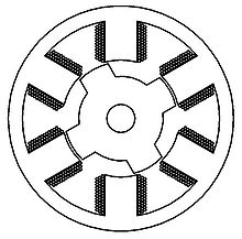
Turquoise Bipolar BLDC Motor Controller Problem Identified?
Readers will know that I've had trouble with my
controllers blowing transistors at higher currents, which problem I
haven't managed to solve. In working out the
unipolar controller, I suddenly realized a mistake I was making. Bypass
capacitors are used on each transistor pair. I was soldering the
capacitors right to the source of one and the drain of the other
mosfet. That seemed the most direct and shortest path. But the sources
aren't connected directly to ground, they go through the shunt
resistance to ground. As the coil current rises,
the
voltage across the shunt resistor should rise to match the current, and
end the cycle at the cutoff current.
But the voltage across the shunt can only rise as it pulls
voltage off the bypass capacitors, since they are on the wrong side.
Thus, the indication of high current is delayed. Perhaps at higher
currents it's delayed long enough to burn out transistors before the
cycle shuts off? On the other hand, the capacitors will continue to
charge and draw current while the transistors are off, leading to
falsely high readings at other times, which may somewhat negate the
problem. But putting the capacitors direct to ground is certainly
something to
try out.
Mazda RX7 New
Battery/140 volts notes
On the 6th I installed the new 11th battery in the Mazda
RX7 EV, bringing it up to 140 nominal volts. Hopefully it'd be back to
at least 7 miles range again. On the 9th, quite a warm day, I drove 3.4
miles using just 252 WH per mile (1.8 AH/mile @140v) instead of about
300 WH or more (2.3+ AH/mile @128v).
That's over 15% less energy per distance, where
theoretically there'd be a 9% drop in amp-hours compensating for the 9%
rise in voltage and watts would be the same. One must conclude that
using a lower voltage reduces efficiency somewhere. Where might that be
but in the motor itself, which is made for 144 volts? That's on top of
reduced currents putting less strain on the batteries and giving them
effectively more amp-hours, a separate range increasing factor.
One might be tempted to want to add those last 4 volts to
bring it to 144 nominal volts. The NiMH batteries, of which there are
5, put out around 13 volts instead of 12 when well charged, so it
should already have it. But all the batteries drop in voltage under
load on hills or accelerating. One suspects that with 150 amp-hour or
higher batteries instead of 100, for better current drive as well as
the capacity, the range of the car would be much more useful, even
doubled. But I'd have to pretty much start over with new arrangements.
The next day a 4.6 mile drive had more stop-and-go and
used 280 WH/mile, but it probably still took ~15% less energy than a
similar drive with the 128 volts.
The next day a more "liberal" 6.1 mile drive with somewhat
higher speeds and some faster accelerations used 308 WH/mile and
brought that weaker NiMH battery down below 10.0 volts at one point
nearing home. I decided I should do something about it. I'd noticed
that there was room for a third "quintos" pack with the two put in a
month ago, and I decided to bring the weak battery up to 110 amp-hours
with an extra one. While I was putting it in I noticed an end had
popped off one of the main long tubes. I pushed it back (about 1/8")
with a screwdriver and applied some methylene chloride to 'glue' it
back on. So! At least one of the tubes surely had no connection,
bringing it down originally to 80 AH. That would explain why it was
weaker. Maybe now it'll be the strongest one?
Two lessons may be taken:
1. There's no way to tell if all the cells in the tubes are making
connection. I
don't trust multiple tubes of batteries as I've been making them, and
have wanted to disassemble them and solder them together.
2. Don't connect batteries with bars or heavy straps where there's
movement and vibration. Use stranded wire that will flex and not put a
strain on the connections.
But now I'm thinking that maybe with some sort of spring on one end
(instead of gluing both ends) they could be made more reliable. Maybe
an external spring? Or one around the inside portion of the terminal
bolt? (The usual flashlight tube internal coil springs have inductance,
most undesirable in high current, switching circuits.)
As it is, that battery still drops voltage most under
load, but now it often comes back to a slightly higher voltage than its
"twin" instead of the same or slightly lower. The problem indeed seems
to be current capacity (gradual loss of electrolyte?) rather than
energy storage capacity.
Towards the end of the month I used the RX7 for a number of trips, and
everything seemed pretty good... except the clutch cylinder started
sticking again, and the lack of clutch travel made shifting while in
motion quite difficult. I've already disassembled and repaired that
clutch cylinder once! Is everything going to start quitting again?
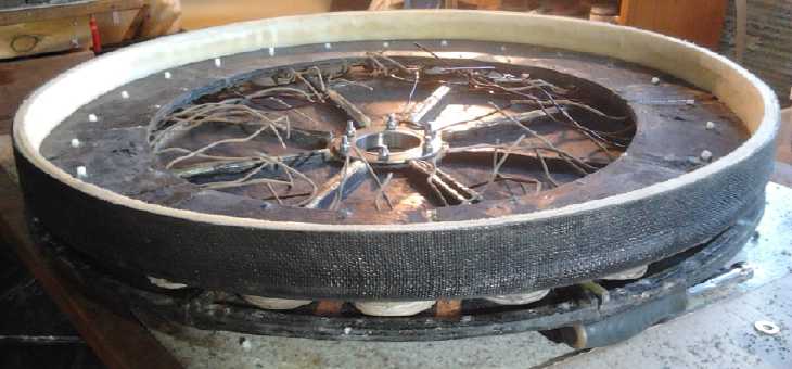
Electric
Weel
Motor
(Generator)
The last major items for this machine were the lexan rotor
plate and a magnet placement jig (CNC design & G-Code for
both). Lexan is much lighter than steel, but it would have a steel ring
around the outside to carry the magnetic fields.
But the person I bought the tilapia fish off of also was
doing some interesting electrical things. And he had two big surplus PM
elevator
motors of very low RPM and something like 12 and 20 HP, with no
cogging, which he showed
me in December or January. Those seemed ideal for the floating hydro
project, so I mentioned them to the developer. If that project used one
of those, he wouldn't need the Electric Weel. (If that was the case,
I'd
probably make it into a unipolar motor instead of a generator.)
Side view of motor without rotor, shaft and rotor end cover.
Coils remain to be wired and the ends of the nylon bolts were later cut
off.
Inner and outer (stainless steel) body clamping bolts remain to be
installed.

View from the stator end.
On the 13th the developer called. He had finally checked
out the elevator motors. They seemed
very suitable, but the present owner, who works for the elevator
company, didn't like the idea of them being used
"commercially" (whatever that means for an R & D prototype!), and
anyway new ones were too costly to consider if the hydro units were to
be commercialized. So he wanted to finish the
Weel.
He came over and drilled the holes and we assembled the
stator side.
As there's lots of room inside and excellent access, we just left the
wires sticking in
toward the middle for wiring later. The rim was a bit thin around the
outside and we decided to use #10-24 stainless steel bolts on the
inside area (which is farther from the magnets) and the rim area, using
1/4" nylon bolts only for the coil centers where metal would be
magnetically heated the most. Perhaps the hypothetical next one should
have 3 or 4 layers of strapping/webbing epoxied around the outside
instead of 2, to ensure sufficient substance for nylon 1/4" bolts.
With the rotor cover on and the bearings and (15" long,
1.75") shaft - everything
except the rotor - the unit weighed only 58 pounds! With the lexan
rotor, hopefully it'll be only about 80 pounds complete. For a low RPM
unit
probably good for almost 20KW continuous, one would usually expect to
need a hoist to lift it.
Lexan Rotor
The project
having become active again, I came up with a
new idea. The 26" O.D.
steel ring around the outside holds the magnets, and instead of making
the lexan piece 26" as well, I made it the exact inside
diameter of the
ring. Thus it would fit flush with the metal. The slots for the magnet
strapping would be [were] router cut through the lexan, and the epoxied
straps
would wrap around both lexan and steel (and the magnets) to bond
everything together. The strong outer steel ring should ensure no
catastrophic failure of the plastic owing to centrifugal forces
twisting the magnets.
I wrote some the G-Code for
routing out the lexan rotor and its slots in the afternoon, and more in
the evening. Not liking the closeness of the slots to each other and
the resulting thin bridges of lexan between them on the display, I
re-did it with
shorter slots, and then again, still shorter. The first slots would
easily accommodate 1.5" wide strapping. The final ones were only 1.1"
long... plus the 1/4" router bit diameter: 1.35". One just might still
squeeze 1.5" wide PP strapping through them
- I'll see when I try it. Aside from extra strength, if wider strapping
'droops' over the edges of the magnets, 1/4" on each side, then even if
a magnet actually came loose, it would theoretically have nowhere to go.
Late in the evening of the 16th I readied the lexan and
set up the CNC router. I adjusted the program to cut the outer diameter
last, so the screws at the outside corners holding the piece in place
wouldn't be cut away until the final cut. It cut well, tho it didn't
quite go through the plastic in some areas, so I had to lower the
router bit a bit and redo it.
On the 17th I dealt with the outer ring of 3/16" steel,
still spot welded to the original rotor plate of 1/8" steel. I used a
zip disk/angle grinder and cut away the 18 or so welds, and then ground
off the rough weld protrusions into the center of the ring. Somehow the
lexan was 3 or 4 millimeters too large in diameter, and I sanded off
all around the outside on the belt sander, twice, until it fit nicely
into the center of the ring.
On the 19th I cut three lexan reinforcing pieces for the
rotor. These are smaller diameter pieces (13", 8" & 6" O.D.) with
identical centers, which will glue to the main rotor piece and to each
other. The stack is almost an inch thick, and instead of one keyslot, I
planned keys and slots on opposite sides of the shaft, to give twice as
much again gripping surface. Lexan obviously isn't as strong as steel,
and by broad contact area I hope to compensate. BTW of course the
router
couldn't cut the sharp keyslot inside corners in the lexan, so they'd
be filed out by hand, and lastly all glued together, when the shaft is
ready.
Total Weight Estimate
I checked the weight of the various pieces. The original
steel main rotor piece was 19 pounds. The lexan replacement was 3
pounds. The outer steel ring, still needed to complete magnetic
circuits, was 6 pounds. Thus the rotor went from 25 pounds to 9. That's
before magnets, and before adding the lexan reinforcement
pieces to strengthen the center of the rotor. Those things may add
about 11 pounds or so.
So the total weight should be 58 + 20 = 78 pounds or so.
Call it 80. That's featherweight for a low RPM machine headed for 20KW
of capacity.
"Green" Electric Equipment Projects
Aquaponics
& LED Grow Lighting Project
On the 14th I got a
'new' 5 gallon aquarium, and I filled it and transferred the baby fish
from a small pail into it. Once I could see them from the side instead
of just the top, I discovered that all but one were guppies! They had
bred about a day later than the tilapia. Now I'm kicking myself for not
filling the bucket and transferring each one to it as it appeared.
Surely several baby tilapia must have been eaten by the adults.

That evening it occurred to
me that I needed a water tank
for summer garden watering owing to the rising price of city water (in
a land
where the yard is flooded half the winter!), and also I was going to
make some sort of expanded aquaponics fish pond. What about a plastic
swimming pool for both? I looked on UsedVictoria.com and found an
inflatable one for 50$ complete with filter, pump, patch kit (might be
vital!), ladder, and every accessory, even the original manual and box:
"best offer takes". There was nothing else like it in the ads. I
offered 70$ and
it was brought from the town where it was to my place the next day. The
extra 20$ probably saved me from 2 or 3 hours of driving. Meanwhile,
the
weather had turned from months of drizzle and flooded lawn to sunny and
drying, almost overnight. Now I hope I can get it set up
and then there's enough rain before summer to fill it!
Where to put it was a problem. My original idea was to put
it in the garden where (hopefully) the deer couldn't reach it to
possibly stab it with their hooves. But at 14' diameter - and around
11,000 litres - it was so big
it would take up half the garden. It was huge! I finally (with some
help) emptied and removed a 'temporary' shed and leveled a presently
muddy patch of dirt/lawn in the back yard for it.
I started thinking that it might not be a good idea to put
fish in
that huge inflatable pool. If deer should get to it they might puncture
it with their hoofs getting a drink. And raccoons with sharp claws and
teeth would surely try to go fishing in it. I would hate to come out
and find all the fish lying dead on the bottom of a deflated, empty
pool. Even if I was in time, where would I then put them all?
Furthermore, now it wouldn't be in the garden by the greenhouse with
the
other components of the aquaponics system. And on top of all that, if
it
got cold, it would be really hard to heat so much water - and even to
net the fish!
I decided to use the pool for rain water storage for
garden watering, and to dig a trough in the greenhouse for the fish
(and use the filter, pump et al from the pool for it). Rubber pond
liners are available to line such excavations, and my brother has had
several such ponds in his back yard for years that haven't sprung any
leaks yet.
On the 26th I got a 5' x 10' piece of liner. A friend and
I started clearing the area for the pool, and I thought about... where
did
I really want to dig to put the fish?
The beans continued to grow, and their roots to spread
throughout the grow bed, and into the bell syphon where I had to keep
ripping them out to keep it flowing properly. They still had no
flowers. Some people told me they wouldn't flower until the days
started getting shorter, but others said "They bloom all summer - they
should be flowering." So they were probably lacking some mineral.
Seeing they had plenty of nitrogen, and since I had added potassium
(hydroxide) at one point (albeit quite a while ago), on about the 20th
I added a teaspoon of sodium phosphate to the water. There was still no
sign of flower buds by the end of the month. If I hadn't planted the
beans, surely I could be eating lettuce leaves and basil (the most
popular aquaponics plant?) by now. But the beans shade out the light
and their roots fill the 'soil'. Doubtless their prolific growth is
keeping nitrogen levels down in the water - but I really should test it.
It had come to light that the primary cause of arthritis
is boron deficiency, as revealed in recent studies by an Australian
physician who also studied minerals. He moved to a new area and
couldn't understand why he had so few cases of arthritis there, when
there had been so many where he had been.
Where the soil has lots of boron, virtually nobody has
arthritis. Where it's very low, it's over 1/2 the population. (I
purchased some 3mg boron pills from a heath pharmacy. Now it's in short
supply as the news spreads. Evidently the pharmaceuticals industry
tried to have the doctor thrown in jail "for selling 'poisonous'
boron", and he had to defend himself in court, but luckily others
supported his findings. Motive: Shut the doctor up! Who will buy our
lucrative arthritis 'remedies' that cost many millions to develop if no
one has arthritis?)
Even before hearing about this, someone I met was raving
that taking borax had cured his arthritis, and that of the person who
had told him about it. I decided to add a teaspoon of borax to the
water and let the plants process it.
This brings up a wider question. Recent studies,
notably by the UN Food and Agriculture Organization (FAO) have declared
our present methods of agriculture to be unsustainable. While chemical
fertilizers replenish nitrogen, phosphorus and potassium, many trace
minerals are insidiously being gradually depleted from farmland soil,
causing gradually increasing levels of health problems such as
arthritis, possibly increased prevalence of allergies, and probable
increased susceptibilities to diseases, for all of which the origin is
hard to trace back to the root problem, the soil.
(Furthermore, other studies indicate that peak production
of food occurred in many of the 21 main types of food that people eat,
from rice and meat to eggs and milk, from about 1988 to 2008. Some
foods have fallen in production since their peak. But the world
population - so far - continues to grow.)
The little tilapia started the month almost the size of an
adult guppy. By the end it was about four times the size (~1.5" long
and substantially taller). The 5 'big' tilapia were also growing and
were mostly about 8" long or more, the large female being 10". They'll
want those larger quarters soon, and the level of the fish food in the
big coffee tin has dropped to half.
Electricity
Storage
(Sorry, No Report on Turquoise Battery Project)
Leonardo Elionix's Manganese-air
cell
Leonardo Elionix is a fellow battery researcher I've corresponded with
occasionally who obviously knows
more chemistry than I do. He writes of his new cell, which he has been
working on for some time.
<<
Subject: Re: Manganese/Air battery
Date: Thu, 26 Feb 2015 03:00:37 +0100
Hi, Craig
I'm doing it with deep eutectic solvent and this cell works well...
very
well.
Deep eutectic solvent has neutral to slightly acid PH and dissolves
well
discharged MnO and MnO2.
I could even do a flowable anode with nano-Mn, because it stays well
dispersed in DES.
Vapour pressure is so low that no need PTFE at the air cathode.
I'm using 5mm graphitic felt as electrode/air cathode, with a
nonwoven separator, from a compound of manganese powder/graphite
powder as anode.
Need only to find a catalyst for air cathode, because DES dissolves all
metal oxides of transition metals!
OV is 1,62V, because low conduction of DES.
I'm waiting to receive DMSO to make a new DES with higher conductivity.
If you want to replicate, no problems, but please add my name.
Best regards.
Leonardo
>>
I had been considering that manganese-air might work better than
zinc-air if the manganese will hold its metallic state charge. It
should certainly be better for a rechargeable cell. As I've said
before, I got it to hold its charge in KCl-water based solution by
adding 1% antimony sulfide and 3% zirconium silicate as trace
additives. (Seems to me I had trouble with graphite powder - at least
the one I was using. The conductive carbon black may work better.) It
may perhaps hold as-is in the lower pH of the DES, or these
traces may have been added.
I at one time looked for a salt with a low melting point
(preferably below room temperature) but didn't find one. I hadn't heard
of deep eutectic solvents (DES) before, but according to Wikipedia it's
a eutectic mixture of certain salts (various salts and mixtures) that
melts to liquid at room temperature instead of a much higher
temperature. Some DES.es should make potentially exciting electrolytes:
Some types have been used in fuel cells. Some of them will dissolve
much higher concentrations of substances than water. Existing types of
molten-salt-electrolyte based batteries perform very well - but at the
oven
temperatures needed to melt the salt. The idea that vapor pressure (and
hence evaporation I presume) is very low is highly appealing for a cell
with air as one electrode.
DMSO (dimethyl sulf-oxide) is a unique non-toxic aprotic
solvent that I once looked for for battery experiments, that appears to
been made unavailable in British Columbia because some people found
some effective topical medical use for it, that was deemed risky by
someone --
owing to the death of just one user, where the cause of death wasn't
even determined. (By comparison Tylenol kills 50,000 people in the US
each year, IIRC.)
The problem that all metals oxidize in the positive
electrode forced me to use graphite/carbon structures such as graphite
foam and graphite foil. It sounds like here the oxides themselves
dissolve. (Great solvent!) Perhaps heavier transition metal oxides (of
lead, bismuth, gold, platinum or medium weight silver, palladium,
cadmium, indium...) would remain solid.
Apparently it needs improvement with a catalyst and a
higher conducting DES would also be better, but Anything-air batteries
are tricky to implement and the DES idea could solve the big problem of
evaporation of the water. Congratulations to
Leonardo on this fine and very innovative accomplishment!
http://www.TurquoiseEnergy.com
Victoria BC Canada