Turquoise
Energy Ltd. News #86
March 2015 (posted April 3rd)
Victoria BC
by Craig Carmichael
www.TurquoiseEnergy.com
= www.ElectricCaik.com
= www.ElectricHubcap.com
= www.ElectricWeel.com
Highlights:
* A
new design concept for an add-on wheel motor system (see Month in
Brief)
* Porous nickel sheet and powder for nickel battery electrode
(see Month in Brief, Electricity Storage)
Month In Brief
(Project Summaries)
- Aquaponics & LED Lighting Progress - 'Ultra efficient'
Electric Chevy Sprint project to be resumed - Axial Flux Switched
Reluctance Motor (AFSRM, replacing unipolar motor) - Add On Wheel
Motor: a New System Design - AFSRM Generator for Windplants et al -
Electric Weel Generator - My/R & D finances? - The Usual Mazda
Batteries Update - Turquoise
Battery Project: Ni-Ni battery production ideas, great new nickel
negode idea!
In Passing
(Miscellaneous topics, editorial comments & opinionated rants)
- Ceres, Vesta and Vegetation - Unsustainable World Population
Electric Transport - Electric
Hubcap Motor Systems
* 'On hold' Chevy Sprint Electric Hubcap/Planetary gear torque
converter & Centrifugal clutch is to be completed.
* Electric Caik Axial Flux Switched Reluctance Motor - AFSRM (was
unipolar motor)
* Active Reluctance Generators: no cogging and output voltage
regulation!
* A Switched Reluctance EV Motor by Ricardo.com (85KW!), AFSRM design
papers
* Electric Weel - Huge low RPM generator [at last] nears completion
Other "Green"
Electric Equipment Projects
* Aquaponics & LED Grow Lighting - tilapia pool - Beans?!?
* Cordless Lawnmower with NiMH dry cells: User Review
Electricity Generation (No reports)
Electricity Storage - Turquoise Battery
Project (NiMn, NiNi), etc.
* Cylindrical cells with carbon rods?
* Ni-Zn or Ni-Ni acid battery with oxalic acid?
* Ni-Ni cell with nickel-brass sheet for negode?
* To make porous nickel sheets and porous nickel powder! (from
nickel-brass sheet and monel powder)
* Packing peanuts for carbon film, carbon nano-particles?
No Project Reports on: Variable
Torque Converter Transmission, Magnet motor,
Lambda ray collector, evacuated tube heat radiators, CNC
gardening/farming machine.
March in Brief
Aquaponics & LED Lighting Progress
 I spent the early days of the month digging and working on a 'trench'
pond in the garden for the tilapia. it looked like it would be in the
way of access wherever I dug it, then I got the idea to put a bridge
across it. So far that's just a fat plank. There wasn't much extra pond
liner, and I sandwiched the edges between boards to keep it from
drooping down. The building supply ran out of 8x16" paving blocks, and
I bought some cement and sand and made some larger, thicker ones of my
own. I may
get around to a second batch some time.
I spent the early days of the month digging and working on a 'trench'
pond in the garden for the tilapia. it looked like it would be in the
way of access wherever I dug it, then I got the idea to put a bridge
across it. So far that's just a fat plank. There wasn't much extra pond
liner, and I sandwiched the edges between boards to keep it from
drooping down. The building supply ran out of 8x16" paving blocks, and
I bought some cement and sand and made some larger, thicker ones of my
own. I may
get around to a second batch some time.
The water was too cold for tilapia,
and I went to a pet shop and got a dozen goldfish to keep any mosquito
wrigglers out of
the water. (But it's probably too cold for them too.) I got some
duckweed and put it on top, and when there's surplus I can take it in
and
feed it to the tilapia - goldfish don't eat it.
 Inside, the
beans in the aquaponics drain-down bed continued to grow, hitting the
ceiling and
blocking most of the light from the window. One flower appeared for a
couple of days and then wilted, with no more appearing. The beans
were just one of a number of things I planted in there last fall, but
they overgrew everything else and prevented any other crop. I certainly
won't try growing beans in indoor aquaponics again unless I find out
why they're not producing beans.
Inside, the
beans in the aquaponics drain-down bed continued to grow, hitting the
ceiling and
blocking most of the light from the window. One flower appeared for a
couple of days and then wilted, with no more appearing. The beans
were just one of a number of things I planted in there last fall, but
they overgrew everything else and prevented any other crop. I certainly
won't try growing beans in indoor aquaponics again unless I find out
why they're not producing beans.
The tilapia fish also continued to grow. The large female
was almost 12" long in a 12x12x12" space. They will certainly want that
(~400 liter) trench pond once it warms up and I get the beds connected
and a pump running. The little one was 2-1/2" long by month end.
I didn't do anything with LED lighting except decide that
a switching regulator would give a lot more flexibility and perform
better than the linear one, except with certain combinations of
voltages
and emitters which weren't nearly as much "the norm" as I expected them
to be before making and using a few lights with the varying solar
panel/battery system voltages. (And I was so proud of my minimal
components constant current linear regulator circuit!)
Axial Flux Switched Reluctance Motor (AFSRM)
Out of sequence, I'll mention that it now looks like the
AFSRM project now looks like it will stretch out a few months. The
motor, while very doable, is also very different from the BLDC magnet
motor, so there'll be a lot of new design. That suggests it might be a
good idea to complete the current version car drive first. It's all
been sitting nearly assembled and ready to install and try out in the
car. It's worth completing it and seeing if I've finally found a
workable path to a high-efficiency vehicle drive.
 The "switched
reluctance" or "SR" type of motor seemed to
have all the advantages of the bipolar (or unipolar) BLDC types, would
use the same motor controller as I had just made for the unipolar, and
had reduced weight, cost and rotor thickness, plus greatly increased
RPM
capability compared with my rotors with magnets.
The "switched
reluctance" or "SR" type of motor seemed to
have all the advantages of the bipolar (or unipolar) BLDC types, would
use the same motor controller as I had just made for the unipolar, and
had reduced weight, cost and rotor thickness, plus greatly increased
RPM
capability compared with my rotors with magnets.
By about the end of February I made up my mind to convert
the new Electric Caik motor from unipolar to the SR type. The only
differences seemed to be the rotor and perhaps a few stator wiring
changes. The apparent similarity proved to be deceptive.
After thinking about it while working on the tilapia pond,
on the 12th
and 13th I designed a rotor that I hoped would have a relatively low
level of torque ripple, that being said to be the worst feature of the
reluctance type of motor. Later a correspondent pointed out that the
main
reason for the high torque ripple compared to BLDC magnet motors is
that the SR coils can only pull steel, not repel it, so more poles are
needed to get equivalent evenness of forces.
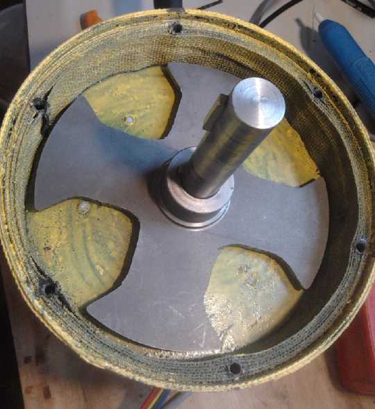
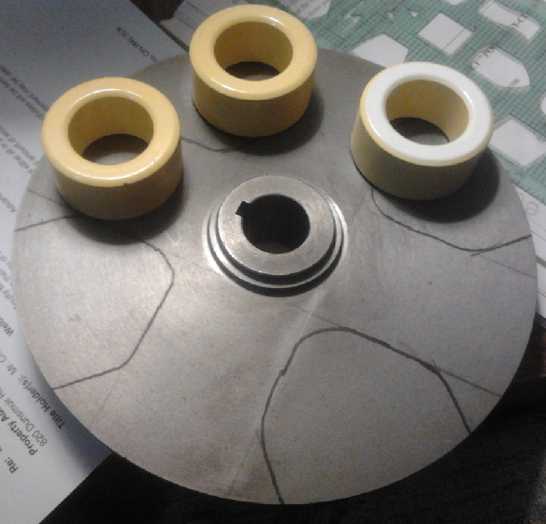
The rotor had the aspect of an "iron cross" with a
circular outside edge, and I made it by cutting out the four sections
between the four "lobes" from a ready-made "brake rotor disk", cast
from "soft magnetic" metal - that wouldn't magnetize when rubbed with a
supermagnet. The
cross section "sort of" followed the curves of the round coil cores.
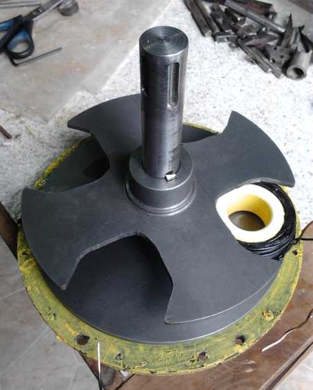
It felt quite different installing a thin, magnetless
rotor that didn't try to grab tools off the bench and suck itself into
the motor unbidden while your fingers were still under it. And once it
was on, it didn't try to cog to different positions. Only the friction
of the grease-stuffed bearings kept it from freely spinning.
It also didn't turn, with 10 amps of current. The magnetic
forces were too weak. The sort of huge flux gaps and plenty of flux for
a relaxed BLDC design is replaced in the SR type by tiny gaps and a
struggle to find enough flux for decent torque. It needed a wholely
different design and layout.
 So I took two
coils, the rotor and the lab power supply to deliver a constant 10 amps
to the coils, and started doing some electromagnetic experiments on the
bench to maximize the forces. These pointed to better ways to go, and I
made modifications that should get things working. A steel plate behind
the coils works to complete the flux circuit. Then someone suggested
using two rotors, one on each side of the stator, to double the flux.
This seemed like a
good plan. I also thought of putting a ring of metal around the outside
rim
of each 'donut' coil to concentrate the flux like in a cup magnet,
where a weak ceramic magnet has "supermagnet" levels of flux in the
small space between the round magnet and the rim surrounding it.
So I took two
coils, the rotor and the lab power supply to deliver a constant 10 amps
to the coils, and started doing some electromagnetic experiments on the
bench to maximize the forces. These pointed to better ways to go, and I
made modifications that should get things working. A steel plate behind
the coils works to complete the flux circuit. Then someone suggested
using two rotors, one on each side of the stator, to double the flux.
This seemed like a
good plan. I also thought of putting a ring of metal around the outside
rim
of each 'donut' coil to concentrate the flux like in a cup magnet,
where a weak ceramic magnet has "supermagnet" levels of flux in the
small space between the round magnet and the rim surrounding it.
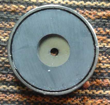 A cup magnet
Although I got the metal, I hadn't found a heavy sheet metal shear to
cut it into 1" strips by month's end. (Tin snips do an ugly job.)
Then in the latter part of the month it occurred to me to
do a web search, and I found two technical papers (PDF.s) describing
axial flux switched reluctance motors (AFSRM.s).
It turns out that the axial flux SRM layout is indeed much
superior to radial flux, but for different reasons than with BLDC
magnet motors. The flat rotors and coils with a flat profile can have
substantially larger adjacent surface areas for flux interaction. Also,
the usual two rotors with the stator between them virtually doubles the
forces available with the same current. With
the right designs, levels of torque can be attained that will move
vehicles by direct drive, for in-wheel motors as small as 12" diameter.
Such motors are however pretty heavy for good vehicle suspension
handling.
I plan to finish my small "AFSRM" as conceived and test
it out, along with the motor controller, which luckily is the same one
as for the unipolar magnet motor, that I designed and made earlier this
year. But the next and larger design for a car motor should probably be
more
along
the lines of the test motor built and tested in the Japanese AFSRM
design paper.
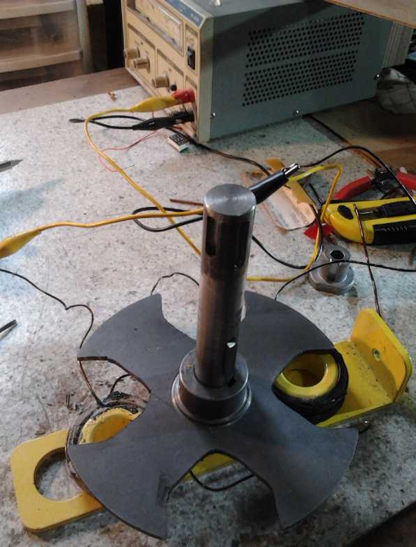
Along the way I made a balanced "arm" to measure static
"locked rotor" torque, in conjunction with a weigh scale. (After
shaping the pointer, I cut and ground metal off an "L" piece at the far
end until it
balanced.) It'll be far
more sensitive than a torque wrench. The "pointer" that presses on the
scale is exactly 6.0" from the center of the shaft, so it's easy to
convert the "weight" measured into foot-pounds.
Add On Wheel Motor: a New System Design
Also along the way, I've conceived what I think should be
a good
solution to large and heavy in-wheel motors, as proposed in the two
papers and many other places. Placing an SRM directly on a wheel's axle
where its RPM
is
limited to the low speed of the wheel, is a waste of one of its big
advantages - the ability to run well and safely at high RPM.s. A motor
running at 0-5000 RPM
will be much
smaller and lighter to get the same power as one running at 0-1000 RPM
connected directly to a car wheel. With 1/5 the torque it is geared
down with a fixed ratio, eg 7 to 1, to deliver sufficient
car-starting torque, and because over-revving for this motor probably
means (say) around 10000 RPM or higher, 7000 RPM on the highway is
fine. The
rotors spinning at such high speeds are (as I envision them) solid
pieces of steel that won't fly apart, and
fairly light as steel rotors go. That means no variable
torque
converter, clutch, or gear shifting is needed. And that leads to
major
simplifications.
The first type of gear reduction that came to mind was a
large planetary gear, perhaps with plastic 'planet' gears to eliminate
lubrication requirements. The motor
would be as originally conceived, in the "hubcap" position, bouncing up
and down with the wheel, probably with some flexible coupling making
for some level of "debounce".
Then a solution that seems superior came to me. The "on
wheel" or "in wheel" motor is conceptually elegant, but then one hits
bumps in the road, which are more easily dealt with without a
considerable extra weight on the wheel. One solution that's been used
is to mount the "wheel" motor within the vehicle. Drive shafts with CV
joints then connect it to the wheel.
My plan, for rear wheel drive only, is (AFAIK) new as
applied to cars: For an outside
"add-on" electric pancake motor mounting, a
telescoping 'arm' runs from the center of the wheel to somewhere on the
car body, either in front of or behind the wheel, about level with it.
(sketch below) The wheel end of the arm moves with the wheel as it
bounces up and down with
bumps. But the body end is almost stationary. The telescoping or flex
mounting piece attached to the car body to
allow the arm to move with the wheel is very short. (Probably with more
than one attachment point for
support against twisting.)
The smaller, lighter motor is mounted on
the arm, near the body end. It doesn't move around very much, thus
it will have little
effect on suspension handling. But being on the arm which is connected
with a bearing et al to the hub of the wheel, its position relative to
the hub of the wheel
is fixed. It is then necessary only to connect the motor to the wheel
with an efficient drive belt: toothed, flat or poly-V, with pulleys
sized to give
the desired reduction. And the pulleys can easily be changed to see
what reduction ratio works best on the road.
By putting the pulley on the axle inside from the wheel,
and
the motor in a "hump" (eg) behind the axle in the luggage space,
the same arrangement could even apply to a vehicle as manufactured,
with the
drive belt replacing the more costly, heavier drive shafts with CV
joints.
There are of course disadvantages. The belt is subject to
wear, and will need occasional replacement. And this drive train, short
as it is, should be more or less enclosed to protect it from road dirt.
...And it just doesn't seem as "cool", somehow, as a motor in line with
the wheel.
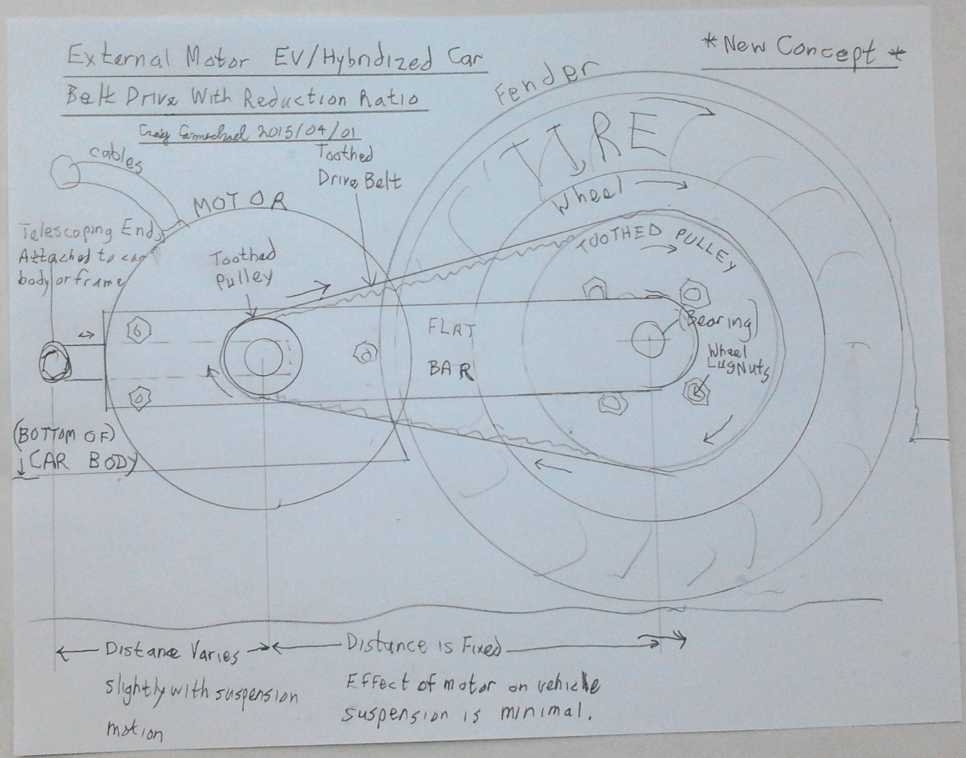 First sketch of the new idea wheel motor
mounting system.
First sketch of the new idea wheel motor
mounting system.
The motor (presumably) is mounted on the front of the bar with the
pulleys behind the bar.
The wheel pulley bolts to the wheel lug nuts, and has a center bearing
to attach the bar to.
Eg:
- Upper and lower body end bolts/pivots can give anti-twisting support,
which it would doubtless need.
- The motor can be mounted right over the pivot point at the back to
minimize effects on suspension/handling.
- Belt adjustments by motor mounting position, eg with slots for the
mounting bolts. (many potential variations)
- Safety cover over the belt & pulleys - to keep out dirt and
gravel as well as fingers.
Suddenly the potential for DIY creation of electric car
drives with small motors at home, including "hybridizing" a gas car
rather than "converting" it, comes back into focus as an attainable
objective!
AFSRM Generator
The absence of cogging also made me think of SRM
potentially as a generator. My
magnet BLDC motors wouldn't be, eg, good wind power generators because
the cogging would prevent them from starting to turn in a lighter
breeze. With no cogging, the reluctance motors should make great
windplant generators. A "problem" is that without a motor controller,
they would just spin without making electricity. On the other hand, with
an appropriate controller they could probably be coerced into putting
out a constant
voltage regardless of RPM. (Within attainable limits of course.) That
would be a tremendous advantage. Where one might have a typical
"passive" generator whose output voltage varies linearly with RPM,
followed by a very flexible DC to DC converter to output a constant
voltage, instead one could have an "active" reluctance generator
putting out a constant voltage at a maximum power point regardless of
wind speed. The DC to DC converter would be replaced by the motor's
controller so the controller would be an alternative electronic
component, not an additional one.
Electric Weel Generator
With a SR generator still being undesigned, work continued
on the original plan for the big generator for the floating hydro power
unit. We got the stator coils wired together and put the magnets on the
rotor. It's almost finished.
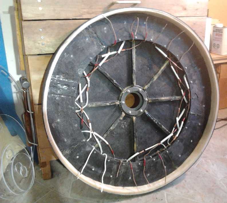
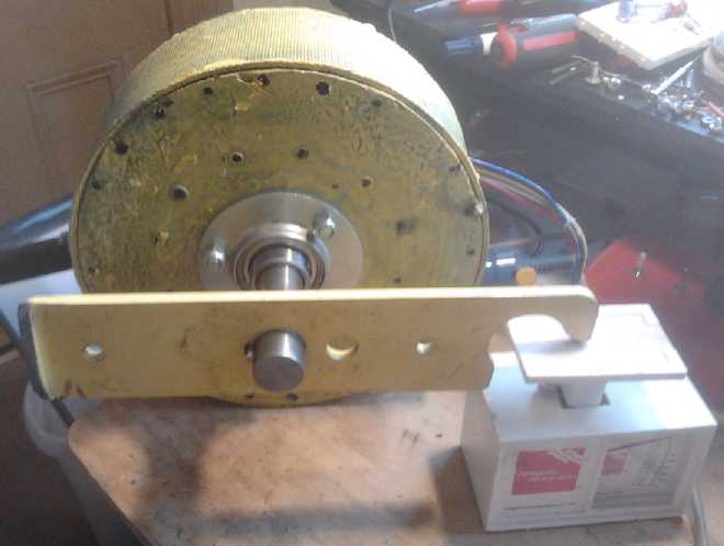
 Magnet Rotor. (More lexan reinforcing pieces
are to be added to this main piece.)
Magnet Rotor. (More lexan reinforcing pieces
are to be added to this main piece.)
My/R & D finances?
I got my first monthly payment of 1000$ from CHIP bank -
owed with interest to be collected someday from my house or estate. I
also applied for Canada pension plan (CPP, 341$). My finances took
another
turn for the worse when I finally got my Turquoise Energy Ltd. income
tax refund for 2013. For every project they didn't like they knocked
off a percentage (just in case I wasn't worth 22000$ for any one or two
of them), and the government has apparently that decided rent
or equivalent for facility space to do R & D doesn't constitute a
legitimate R & D expense. It looked like that would knock it down
to 12000$. But I finally got my 2013 refund on March 20th 2015, nearly
a
year late, and it was even worse: somehow it was beaten down to just
under 8000$. I expect that pretty much covers all the time I spent
doing all the paperwork I have to do to qualify for the SR & ED
program - but not the actual inventive work. It certainly does little
to
compensate for what I've invested in the projects in time and money.
That has been financed with a considerable mortgage on my house. I
wonder how much the audit itself cost the taxpayer, complete with
scientific appraisal by a university academic who seemed to sneer at
the fact that I had no university degree and wasn't going out of my way
to try to get university collaboration. The salaries of the
two Canada Revenue employees are both doubtless far higher than what
I've been living and doing R & D on. Now I've started in on
all the
same paperwork for 2014, all seemingly no less exacting than if I was
claiming millions of dollars. And when will I receive some pittance for
having done that? Another product developer I know, and so probably
many others, have been similarly affected. It seems the
government is cutting everything that won't cause a public uproar (and
apparently
even some things that do),
while it involves Canada in shameful foreign wars and moves us
stealthily toward becoming a lawless police state, in step with the
USA. It doesn't look like
the next advances in human society will come from the west.
The Usual Mazda Batteries Update
The electric Mazda with 11 batteries and 144 volts has
become somewhat more practical
again, but still only for trips under 6 miles or so, or where I can
charge a while at the far end. I've been to a friend's at 5 miles
distance for a 10 mile round trip a couple of times, with a 2-1/2 hour
[slow, float] charge while I'm there, without getting too low
before getting home. OTOH, these were evening trips with light traffic
and I picked a route with few stops and just a couple of steep hills
(relatively short ones), and
used as little as 238 watt-hours per mile (1.7AH/mile @ 140V) rather
than the average of around 280 or more watt-hours. (Now I think I know
how the EV-1
used just 225 WH/mile or so, according to various reports. It's not
that the car was a whole lot better. It's that California is always
warm
(warm lowers consumption) and has fewer steep hills and generally
longer runs
between stops.)
The older NiMH batteries made from "D" cells don't work as well as the
newer ones - the voltages drop more when climbing hills or
accelerating.
Curiously, this doesn't seem to be a reduction in storage capacity,
only in current drive, as the voltages soon come right back up fairly
even
with the new ones after stopping, which means the state of charge is
the same. This suggests that the electrolyte gradually escapes. That
wouldn't hurt a flooded cell (especially as it can usually be
refilled), but the "dry" cell doesn't have much to start with.
I started thinking about the possibility of refilling the
dry cells, by immersing them in water for some period of time. It's an
experiment I'd like to try on some older cells, but I would want to run
a few load tests before and after, and ideally try varying lengths of
time and
depths of immersion, so it'd be a fairly involved set of tests in order
to come up with general guidelines for 'restoring' NiMH dry cells, if
indeed it can be done. And
different size cells - and even different brands - would probably have
different requirements.
I'll want more "identical" batteries, eg, 3 x 300AH of
NiMH.s, if I get the Chevy Sprint going with a 36 volt motor. I thought
about investing another 3000$ in "D" cells to get there. Ugh! What
about my own batteries? Surely there must be some way to make use of
the new chemistries I've found instead of just paying through the nose
for NiMH or lithium!
Turquoise Battery Project: Battery Production Ideas
I have two
fabulous new chemistries. But I don't seem to be able to make practical
batteries. I even started thinking about the nickel-zinc oxalic acid
cells again (might not care about air exposure?), and about sheet zinc
as an electrode. I thought about the way standard dry cells are made,
and the fact that they work well and their carbon rod is just what
would work with my salt electrolyte posodes. What about simply using
the rods from "D" or "F" dry cells and adopting the same construction?
Nickel-nickel with salt electrolyte should be doable as a dry cell.
(The high voltage of nickel-manganese, fantastic chemistry attainment
that it is, would make for too much gassing and pressure - they pretty
much would have to be flooded, vented or valve regulated cells.)
Then I figured that I could use the nickel-brass sheets as
the
outer layer, with the nickel in them as part of the nickel electrode. I
would assume the (18%) zinc would oxidize away leaving
the nickel (17%), active wherever it was exposed to the electrolyte,
and the copper (65%) as current collector. That would ensure some sort
of high-current active nickel electrode, but with quite low amp-hour
capacity.
Then I thought such an electrode might be improved by
dissolving away both the zinc and some or even all of the copper, to
leave a microscopically porous
nickel electrode. (17% nickel and 83% air space for electrolyte
penetration.) On April 1st and 2nd I extended this great idea. I have
the nickel-brass sheets, and
also monel powder (Ni:Cu 66:33%). If some or all of the copper was
leached
out of both these alloys (and all or most of the zinc) with HCl and
H2O2 (or
maybe ferric chloride), microscopically porous nickel should remain,
with mostly nickel on the surface, exposed to the electrolyte, and any
remaining copper inside as a highly conductive backing. That should
make a relatively solid electrode with very high current capacity and a
lot of microscopically rough, exposed nickel surface
and hence excellent amp-hours per amount of nickel. One might be able
to apply a flux [water soluble?] and sinter the powder and the sheet
together into a porous electrode with a torch, then dissolve
out the zinc and [some of?] the copper to also get the microscopic
porosity. It sounds like a real winner!
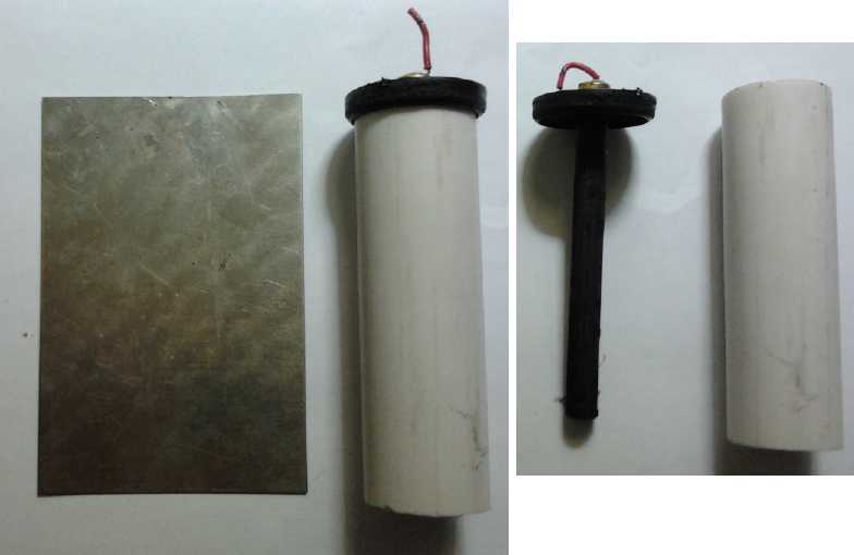 A nickel-brass (AKA "nickel-silver" or "German
silver") sheet to turn into a rolled-up electrode,
A nickel-brass (AKA "nickel-silver" or "German
silver") sheet to turn into a rolled-up electrode,
with an "F" cell carbon rod and its original plastic cap, and the
prospective PVC 3/4"
plumbing pipe as an outer casing. (Sigh - the '3/4" end cap' for the
bottom was the wrong size.)
On April 2nd I tried an
initial experiment, tossing the piece of nickel-brass into a solution
of HCl + H2O2 I had sitting in a jar for printed circuit board etching,
for about an hour. I taped over one side so as to etch only the other.
Sure enough, the exposed surface looked very different when it came
out. It had a 'matte' appearance instead of glossy, and a rough texture
with fine ridges instead of smooth under a 40 x magnifiying glass. It
looked very promising and I'll have more info next month. (I wish again
I had a microscope. Maybe I can get someone to put some samples under
the fab UVic electron microscope.) By evening I realized that that
solution doubtless dissolves nickel as well as the other
metals, so I'll have to look up something else. Edison used sulfuric
acid to dissolve copper from nickel, dissolving only a little nickel,
so it's known to be doable. I think I'll try ferric chloride. It might
dissolve no nickel at all.
Another interesting find
was that someone has discovered that parcel
packing "peanuts" can be turned into thin carbon film or carbon
nanoparticles (depending on formulation) useful for battery electrodes,
by heating in a kiln in an inert atmosphere, and sometimes with the
right salts added. (The salts used weren't listed). A friend sent me a
link
to the article. I may look for ways to try it out. The hard part will
be keeping the air out, and I've wanted to be able to do that in the
kiln for a number of things.
In Passing
(Miscellaneous topics, editorial comments & opinionated rants)
Ceres, Vesta & Vegetation

I searched youtube for any
more information about the Dawn
spacecraft mission to Ceres. Specifically I was hoping for information
about potential "polycyclic aromatic hydrocarbons" spectral findings or
"fluffy" surface textures that might (or might not)
support the visual appearance of Ceres as having the same strange
vegetation (assuming that's what it is) evident on several airless
worlds
of the Jupiter and Saturn systems. There was a 50 minute NASA/JPL press
briefing about Dawn entering Ceres orbit, but no one asked about those
topics. There was much interest in the two "mysterious" bright spots.
Since the bright spots appear to stick up above the
surrounding surface, they're almost surely ice extrusions formed by
expanding water, pushing up through holes or cracks and then freezing,
following meteor impacts that melt the ice into a pool that quickly
forms a crust. I have yet to hear this or any plausible explanation for
such features, which are ubiquitous on many worlds, from the space
science community. Unless that's what are being referred to as
"cryovolcanoes". But they'd be very short lived as active phenomena -
probably minutes to a very few hours, depending on the size and energy
of the impact.
In the search for info, I ran across several
quite "out there" videos: The
bright spots are alien lights. Jpeg images blown up into pixelated
squares show an alien city with square buildings. Ceres has air and
water. (!)
One starts to see why it's hardly possible to speak
rationally
of evidence for life on space forums without having people instantly
eject you from their membership without bothering to read what you have
to say. And Ceres is, after all, just an "oid" about 2% the size of
Earth's moon. (BTW: Evidently the equatorial diameter is substantially
greater than the polar diameter: 950Km versus 910Km, slightly different
than the figure of 915Km I used last month. Since the gravity is
so slight and the rotational period is just 9 hours, this oblateness
may perhaps be accounted for by centrifugal force. Hmm... Saturn, which
rotates every 10 hours, is similarly oblate.)
Dawn had already been to the second largest (but much
smaller) asteroid, Vesta, before it went to Ceres. What might be so
different that Ceres has a similar appearance to Jupiter/Saturn
"fluffy" icy moons, while Vesta looks more like a simple rock, like
Earth's moon?
Apparently, it's just enough of a temperature difference that all the
water ice has sublimated off Vesta (max. 253°K, -20°C), while
most of it has remained on Ceres (max 235°K, -38°C) so far.
Vesta is just a little closer to the sun. But both are much warmer than
Ganymede (~140°K) where the apparent vegetation doubtless
originated. So far the only real indication I've seen of vegetation is
the low albedo and the high contrast with the bright spots. This is
perhaps a rather superficial indication, and with such a temperature
difference, certainly more evidence is required one way or the other.
Hmm... I guess there's nothing stopping me from doing my
own video to explain what I think is, and might be, going on!... except
finding time to do it. I can see quickly wanting to make it into a
half-decent production, bringing in images and other findings from
other worlds to compare and illustrate the points. It would become yet
another project - AWG!
I was disappointed to hear in the press briefing that
Dawn's
orbit is only going down to something over 100 Km from the surface. (I
don't remember the exact figure.) It should surely be possible to get
down to 30 or even 10 Km above the tallest features to sample some of
the finer details... like "fluffy" vegetation. Perhaps it's not time
for humanity to indisputably see and recognize alien life.
Unsustainable World Population
It has been said that in primitive 'caveman' times the
world population was about 10 million. But this can hardly be true! It
was also estimated that before 1550 (before smallpox) there were about
50
million native
inhabitants of North America. This figure, for primitive
hunter-gatherer
societies often (if not usually) at war with each other, is quite at
odds with such an extraordinarily low global estimate. If North America
contains, say, around 10% of the world's productive land area (besides
desert or arctic), we may estimate that the world population for much
of our million year history was probably around 500 million primitive
people.
As herding and simple agriculture became common, the food
productivity and hence the population per area ratio perhaps
quadrupled. This would indicate that the world could, and probably did,
support around 2 billion people in more recent millennia. (IIRC, the
population before world war one was around 1.8 billion.)
When agriculture started to become mechanized, more people
moved to cities and the land was gradually converted to huge farms -
"agribusiness", and an enormous population expansion began. (I remember
in elementary school (~1964) my teacher mentioned to the class, and was
shocked,
that the population had reached 3 billion people!) It is now well over
7
billion, and there are numerous very serious food concerns. Not only
can bad crop years result in shortages, and not only is farming
presently dependent on fossil fuel*, but with the gradual loss of
various trace minerals from farmland soil without replacement it's been
said by a USDA
study to be
unsustainable (which is in fact obvious without a study). The rising
rate of arthritis, which evidently stems mainly from boron deficiency,
is
just one health affect just now being linked to this - to boron poor
soil. Besides food,
various resources including land are in
short supply and the quality of life is deteriorating rapidly. This is
exacerbated by the greed and hoarding of a few, and their fears of
"uprisings", and war. (There are
today over 50 million displaced refugees - more than at any time since
world war two.) As stock analyst Greg Mannarino puts it on youtube,
"The
population is in a bubble, and when that bubble bursts, there'll be
suffering on a biblical scale. People won't have the resources to
procure
the basic necessities they need to sustain their existence." (Not an
exact quote.)
According to various internet sources, some who rule our
world would like to see the population reduced to 500 million, and they
scheme means to accomplish it without bothering to inform people of
their
intent, educate them on the need for population reduction, determine
public opinion or explore peaceful, agreeable methods to accomplish it.
Obviously 500 million is almost absurdly small - a cave days
"hunter-gatherer" population and just 7% of the present population.
It might put an end to human progress. Certainly much would be run down
and abandoned.
They needn't fret now about the growing population because
in the
economic collapse looming in front of us, it's going to drop sharply.
The most shocking estimates of "9 out of 10 Americans will soon be
dead" seem disproportionate, but "1 out of 2" would probably be
optimistic and "2 out of 3" to "3 out of 4" more likely. It seems
likely to come out around 2 to 2.5 billion people remaining by perhaps
mid century - about where it was when the 20th century began. Again
while spectacular events and disasters are inevitable, most of the
deaths will probably finally result from plagues**. At some point of
overcrowding and poverty, these become inevitable.
Hopefully the survivors, with the global awakening and
quickening of consciousness that is and will be taking place, and the
spread of knowledge via
the internet, will have the wherewithal to start a better civilization
- and to voluntarily regulate their numbers so everyone has enough for
prosperity.
- - - - -
* To get agriculture off oil, not only
is there the CNC gardening/farming machine idea (which would be powered
from the electrical grid), but there seem to be a number of
battery-electric tractor conversions out there. An electric tractor may
be more
practical at the present time than an electric car because it's never
far from home and from its charging station - or perhaps from a quick
battery swap.
** An interesting youtube news show that follows an amazing number of
major events
and "top importance" topics including food and disease concerns is "The
News in Two Minutes" (TheNITM") presented daily Monday to Friday by
"FullSpectrumSurvival" channel. It's hard to keep up with the dizzying
pace at which the news items (with relevant web pages pictured) are
presented!
It's quite an antidote for TV "nothing happening here" news where
usually one doesn't get the
impression that events of real import are happening daily often in
rapid
succession all around the globe.
Newsletters Index/Highlights: http://www.TurquoiseEnergy.com/news/index.html
Construction Manuals and information:
- Electric Hubcap Family Motors - Turquoise Motor Controllers
- Preliminary Ni-Mn, Ni-Ni Battery Making book
Products Catalog:
- Electric Hubcap 7.2 KW BLDC Pancake Motor Kit
- Electric
Caik 4.8 KW BLDC Pancake Motor Kit
- NiMH Handy Battery Sticks, 12v battery trays & Dry
Cells (cheapest NiMH
prices in Victoria BC)
- LED Light Fixtures
(Will accept BITCOIN digital currency)
...all at: http://www.TurquoiseEnergy.com/
(orders: e-mail craig@saers.com)
Daily
Log
(time accounting, mainly for CRA - SR & ED assessment purposes)
1-2nd: Finished February newsletter/report (#85)
3-12: Made insulated outdoor tilapia pond
12-13: Designed motor rotor to convert Electric caik motor from
"unipolar" to "switched reluctance" ("SR") type.
14: Made rotor. Made "torque bar" for measuring motor torque.
15: Installed rotor and ran a test. (which showed stator wiring needs
modification for SR operation.)
16: Worked on Electric Weel development - finished stator assembly,
wired stator coils together.
18: inverted 3 of 6 coils in Caik SR motor. Still no apparent torque.
19: Ran various magnetic experiments with two types of motor coils, the
SR rotor, a steel backing bar, and supermagnets and a supermagnet
rotor. Electric Weel: started installing magnets on rotor.
20: Ran a couple more SR motor experiment variations (repeated some to
verify impressions).
21, 22: Studied up on SR motor control "standard practices" &
advancing ideas & projects.
23: Glued remaining magnets to Weel rotor.
24: Searched for pipe suitable for making rings around coils for AFSRM.
(no luck.) E-mail conversation with a designer about AFSRM design.
25: Bought 2nd rotor for AFSRM.
26: Epoxied strapping to Weel magnet rotor.
27: Got sheet steel to make coil rings from.
28: Battery Production ideas. (I have two better chemistries... now,
how to make
batteries that work and are practical?)
31: Studied another theory paper of axial flux motors for EV.s,
describing a motor very similar to what I want to build.
Technical Papers Studied:
A Novel Approach to the Design of Axial-Flux Switched-Reluctance Motors
Tim Lambert *, Mohammad Biglarbegian and Shohel Mahmud
School of Engineering, University of Guelph, Guelph, ON N1G 2T6,
Canada;
A Design of Axial-gap Switched Reluctance Motor for In-Wheel
Direct-Drive EV
Tohru Shibamoto, Kenji Nakamura, Hiroki Goto and Osamu Ichinokura
Elec. and Comm. Eng. Dept., Tohoku University
Electric Hubcap Motor Systems - Electric Transport
Electric Caik
Switched
Reluctance Motor
The more I look at reluctance motors, the more I like
them! The more one looks, the more their unique physical and
operational features bring tremendous application advantages to the
imagination.
A Revolution for Car Hybridization?
The SR motor should prove compact and light, and if the rotor is
balanced, capable of running safely at very high RPM.s. Where my BLDC
magnet motors might be good for 2500-3000 RPM if the magnets are well
attached to the rotor (per the latest Electric Caik & Electric
Weel construction), the SR motor with a simple solid steel plate
rotor might be good for perhaps 8000-10000 RPM or more. If it has
enough torque, and if it's geared down enough, it might be mounted on a
car wheel simply with a fixed gear (or belt) providing sufficient speed
reduction/torque increase to reliably start the car moving rapidly or
uphill. The RPM on the highway can be very high without being dangerous
or wasting a lot of power. Thus the variable torque converter could be
dispensed with! That would revolutionize all my plans and bring the
wheel
mounted car hybridizing system back into immediate focus.
Furthermore, 5000-6000 RPM for the Electric Caik size
(doubtless quite attainable) is plenty high enough to get a small
motorboat up on a plane in outboard motor conversions, driving the main
shaft directly and without changing the typical manufacturer's gear
reduction down by the propeller, which is so frustrating for
conversions using typical higher torque, lower RPM BLDC motors.
Such potential benefits were completely unforeseen when I
started the unipolar motor project, which has turned into the switched
reluctance motor project!
I had been thinking the gearing down could be accomplished
by a planetary gear, with the motor directly in front of the wheel. But
near the end of the month, I thought of what seems like a very elegant
solution with a drive belt, as described in Month in Brief.
This simple installation plan brings mounting an external add-on motor
to "hybridize" a vehicle back into close-up focus, as an easy DIY
project.
Meanwhile Back at the Ranch...
Of course the layout of the motor, as per the usual BLDC
case, is 3-phase and in fact for the Electric Caik is like the
image below except for being axial flux instead of radial. The
Fleadh Electronics Ltd. web site has this to say [My boldings]:
<<
Switched Reluctance Motor Drives - http://www.fleadh.co.uk/srm.htm
 Three-Phase Motor
Offers simplest solution to
starting and torque ripple without resorting to high numbers of
phases. Hence has been the most popular topology in its 6/4
form.
Alternative 3-phase machines with doubled-up pole numbers can offer a
better solution for lower speed applications. But again watch-out for
torque ripple especially in the voltage control single-pulse operating
mode.
>>
(Perhaps it's noteworthy
that this company includes major electrical equipment and motor
manufacturers such as Baldor in their client list.) Another document I
found said (among other things):
<<
SRM Summary (www.SRMDrives.com)
Due to the absence of rotor windings, SRM
is
very simple to construct, has a low inertia and allows an extremely
high-speed operation. <snip> Designing a motor with high
constant power range to base speed (e.g. at least 4:1), is not hard to
achieve with SRM, and has a great effect in designing a lower power
motor that can produce significant torque.
The SRM has many advantages, mostly resulting from its simple
structure: low cost, extremely safe and particularly suitable for
hazardous environments. The SRM drive produces zero or small open
circuit voltage and short circuit current.
Furthermore most SRM converters are simple because the current is
unipolar. The SRM drive is immune from shoot through faults,
unlike
the inverters of induction and brushless dc
motors.
<snip>
>>
SRM Drives speaks of high speed motors up to
100,000 RPM, and while that must describe quite a small diameter motor,
indeed a solid chunk of steel is highly resistant to centrifugal
forces. (But I still remember they guy in the 1970's(?) who was
promoting high speed flywheels for energy storage. His experiments and
grand ideas were featured in Popular Mechanics and Popular
Science magazines month after month (remember when there was no
internet?), until they just stopped appearing. It turned out he had
been killed, and his entire lab destroyed, by the "explosion" of a huge
flywheel at 50,000 RPM. Even the best steel has limits!)
The Electric Hubcap and Electric Weel
would be "Alternative 3-phase machines" with more poles and lobes.
(Come to think of it, the Hubcap version with 3 coils per phase
instead of 2 or 4 might not work out - instead of NS it would have to
be NNS or NSS. This concern was negated by later magnetic
configuration ideas, below.)
In further study of the switched reluctance motor, I
was surprised to see the seeming complexity of the control
circuitry to drive it as shown on Wikipedia.
(In fact, I think the first time I saw the name "reluctance motor" was
in the description of an "Asymetric Bridge Converter", and the weird
circuit, with six wires to the motor coils instead of three, is
what made me reluctant to take any interest in reluctance
motors - plus the name just sounded weird. Unfortunately I didn't even
look them up.) But on closer
inspection, other
than needing 6 power
wires to the motor, it's the same six transistors and six diodes as in
a
'regular' 3-phase bridge driver. But again, as noted in the SRM
Drives summary above, the current is unipolar, and "glitches"
transiently
turning on transistors can't cause a catastrophic short ("shoot through
fault") from B+ to B-. In fact, both transistors of a phase are turned on
to energize the coil - the fault condition in a regular half bridge.
<<
Power Circuitry (Wikipedia)
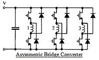 The most
common approach to the powering of a switched reluctance motor is to
use an asymmetric bridge converter.
The most
common approach to the powering of a switched reluctance motor is to
use an asymmetric bridge converter.
There are 3 phases in an asymmetric bridge converter corresponding to
the phases of the switched reluctance motor. If both of the power
switches on either side of the phase are turned on, then that
corresponding phase shall be actuated. Once the current has risen
above the set value, the switch shall turn off. The energy now
stored within the motor winding shall now maintain the current in the
same direction until that energy is depleted.
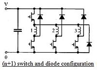
This basic
circuitry may be altered so that fewer components are required although
the circuit shall perform the same action. This efficient circuit is
known as the (n+1) switch and diode configuration.
A capacitor, in either configuration, is used to suppress electrical
and acoustic noise by limiting fluctuations in the supply voltage.
>>
The rising current shutting the coil power off is of
course what I call CRM - current ramp modulation. So my controllers,
ever since the A3938 version in 2011, already have it. (In the MC33035
based
controller so far, it's in an approximate form.) No complex DSP or
processor
control is required to achieve it.
 The yellow lines are current to the active
phase coils. The red lines show inductance with rotation, maximum
The yellow lines are current to the active
phase coils. The red lines show inductance with rotation, maximum
inductance being attained when the rotor pole lines up with the coil.
(The coil should be 'off' by that point of rotation.)
Left: Current ramps up quickly at low speeds and attains destructive
values unless limited.
The rate depends on the
inductance of the coil, which increases as the rotor pole metal goes by.
When the current reaches a
maximum value, the coil is briefly shut off to allow it to drop back
down.
Right: Owing to back EMF, current ramps up slowly at higher speeds, and
either the current limit
isn't reached, or it's reached more slowly and less often and the CRM
is less active or inactive.
If the control current is set lower for less drive to the
motor, all the yellow lines are
reduced in amplitude.
The second "n+1 Switch and Diode" circuit seemed more intriguing at
first. Where I put
in a coil to dissociate the supply voltage from the actual supply to
the coil switches during voltage spikes, this circuit uses another
mosfet. This is probably
superior - more predictable and controllable.
But the high-side transistor is turned on
whenever any of the others is turned on. It'll get hot 3 times as fast.
It would seem then that at least for larger motors such as mine, the
asymetric bridge type is used so as to spread the load between three
sets of drivers.
On the other hand, my controller with the in-line coil has
only
three driver transistor points instead of six, with no troublesome
floating high-side gate drives. If the coil can adequately isolate the
supply from the battery for energy pulse switching purposes, it may be
the optimum solution. It was derived from not knowing what a "standard"
solution might be, since I was initially trying to drive a unipolar
magnet motor - a new type of motor for which I didn't expect to find an
existing type of controller. Occasionally not knowing "standard
practices" in advance can be an advantage!
A problem noted with switched reluctance motors is the
generation of acoustic noise owing to flexing of the stator with
ever-changing magnetic loading. (No doubt this is to an extent true
also of BLDC with magnets on the rotor, and especially it would be of
unipolar.) The
polypropylene-epoxy
composite bodies of my motors should damp the sound and make less
noise than 'ringing' metal bodies.
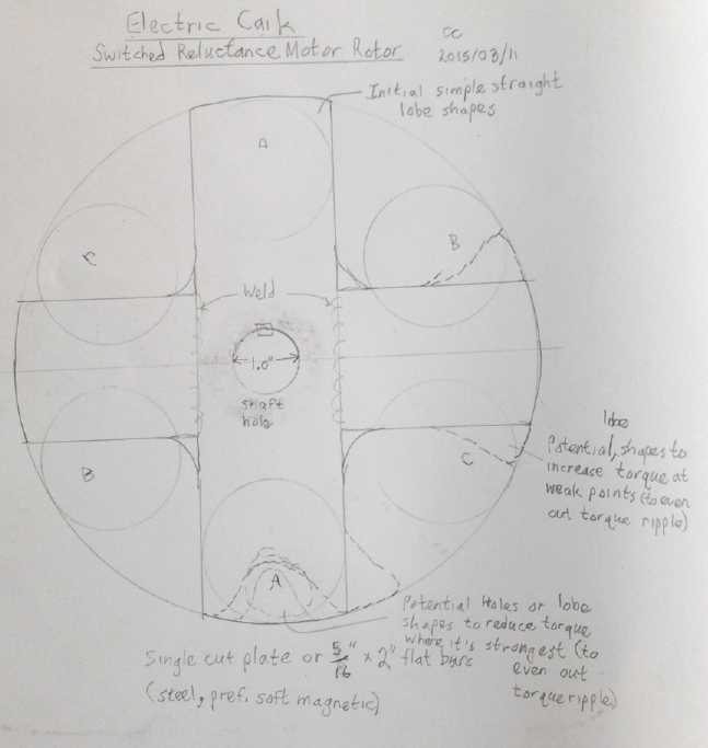 Concept Drawing to define rotor shape
 Another
consideration is electromagnetic inductance into
the rotor steel. Soft magnetic material (eg, high silicon steel) is
used, and some have used laminations or other induced current
restricting materials.
Another
consideration is electromagnetic inductance into
the rotor steel. Soft magnetic material (eg, high silicon steel) is
used, and some have used laminations or other induced current
restricting materials.
I considered using 1/4" x 2" bar stock and welding two
pieces together in an "X" (or something along those lines), drilling
out a 1" center hole for the axle. That would give a "disk" with four
good lobes, but not quite what I thought would be the best shape. I
finally decided that the most practical thing was to take a pre-made
7.8" "disk brake rotor" disk and cut out four shapes to leave the
desired four lobes in what I hoped might be a design with minimized
torque-ripple. My biggest concern was that this rotor was only 3/16"
thick. But at worst, the maximum torque would be lower. It would also
be easier to cut than thicker metal. I drew this up on the evening of
the 12th, drew it on the rotor with a felt pen on the 13th, and cut it
the day after that, using a jigsaw with a metal blade.
It came out looking somewhat like an "iron cross" medal
with the outside edges being the original circular rim segments. The
extra metal around the outside edges should give the coil more to
attract when it first comes on as the lobe approaches it, while having
sufficient clearance between the coil core and the lobe behind, plus it
would spread the center of the lobe and reduce the higher torque as the
lobe approached the center of the coil. Or so went my reasoning. I
thought I cut it pretty well and I didn't try to balance it. First get
it to run! Then the details.
On the 15th I installed
this four-lobed rotor into the
motor. I seemed very strange having no annoying magnetic forces at work
trying to suck the rotor toward the stator. And when it was assembled,
there was no cogging - no force except bearing friction. (...which was
considerable. Oh well, some grease will ooze out of them as it runs.)
And I had
started to consider that a very useful device
would be a torque wrench or other torque measuring device that measured
in "inch-ounces" or some such units instead of "tens of foot-pounds",
that I could put on the motor shaft. That could give an idea not just
of torque, but of torque ripple, by measuring the static torque at
various angles of rotation. A Texas Instruments document suggested that
torque ripple in SR motors can be minimized by careful mechanical
design, which mirrored my own thoughts.
I wasn't seeing what I needed at local auto and tool
stores. Then I thought of making a balanced bar to put on the motor
shaft, with a 'pointer' on one end. This would press on a small
mechanical weigh scale when the motor was energized, to give a reading
in grams or ounces. Knowing the length of the bar, foot-pounds or
newton-meters could be derived, to a fine scale. To find the torque at
different angles of rotation, the whole motor would be rotated to keep
the bar level. Since the first objective would be to measure
differences in torque at different angles, only a small force where the
motor could be held by hand would be applied. (Maybe even just from the
DC lab power supply to one pair of coils at a time, to get exactly the
same current each time.) I made this also on the 15th. I found a nice
bar on which it was simple to shape a 'pointer' to press on the scale,
at exactly 6.0" from the center of the shaft.
Static torque per amp - including maximum and minimum if
there's
much ripple - can be derived by knowing the current which gave the
figures. (That's another reason for using the power supply, in
"constant current" mode.) To measure torque with the motor rotating
will still need something like a dynamometer.
I foresee a problem with determination of back EMF per RPM
("Kv"): With no magnets to induce electricity into the coils, the rotor
can spin freely all it wants and essentially no voltage will be
produced.
Apparently if it's being pulsed by the controller this changes, but it
sounds like it'll start to get complex -- couldn't any desired back EMF
be generated at any RPM?
On the 16th I
hooked up the lab power supply to one set of
coils and turned it on to 10 amps. I turned the rotor to find where the
torque would occur and how strong it would be. (Funny I never thought
of doing this with any previous motor!) To my surprise there was no
apparent force or torque at any point. My best guess was that with a
north electromagnet pole at both ends of the engaged rotor lobes, the
repulsion of the two norths canceled the attraction to the metal.
I'd have to rewire half the coils - or flip them over - to create
north-south magnetic circuits.
I manged to flip 3 coils over on the 18th. But the slotted
optical interrupter
drum seemed to rub on the wires, which I had done my best to get out of
the way. I might need to start banging on them with a hammer to get
them aside! Not my idea of a simple adjustment. For the moment I
removed the drum. I again hooked up the power supply to one pair of
coils, and again there was no perceptible force. If I put a supermagnet
by the coil, I could feel a small amount of repulsion or attraction,
but not with the rotor. And not with a fat chunk of steel that would
stick fast to the supermagnet. My motors with the supermagnet rotors
work great with these coils. Plain steel doesn't seem to work at all.
Apparently with the reluctance motor I was moving into unexpectedly
unfamiliar territory.
Of course, usually motor coils have metal behind them,
connecting them all together magnetically. The coil cores are usually
integral to the die-cut laminates that comprise the stator. Connecting
metal didn't seem to be necessary with the supermagnet motors. Going
from steel backing disks to plastic composites had improved performance
a
lot. The magnets, which were connected together by the steel rotor
plate, seemed to make for a complete enough magnetic circuit. Here the
steel in the rotor just doesn't seem to help. Perhaps I needed to go
back to a metal coil backing plate in the stator? Since there are no
supermagnets to generate current into it, it shouldn't cause the losses
that it did with the supermagnet rotor.
Configuration Experiments
The next
morning (19th) I took two older coils with 63
turns of #14 AWG wire (instead of 21 turns of #11 - normally 3 were
wired in parallel instead of 3 in series to get to 63 turns total for
Electric Hubcap motors) and set them on a steel bar, about the same
distance apart as in the motor, opposite magnetic polarities up. These
would of course give 3 times the force with the same current. I put the
rotor over them and applied the same 10 amps. This time the lobes
pulled fairly strongly down onto the coils. Pulling up on the rotor, it
could just lift the heavy coils and bar. With the coils on the bench
instead
of on the steel bar, the force was much weaker and it would by no means
pick up the coils, or either one alone.
I tried the same thing to repel a single small
supermagnet. It was stronger with the steel backing the coils, but less
notably, and the forces were stronger overall.
Next I tried again with a spare Electric Hubcap magnet
rotor. It
was again somewhat stronger with the plate than without, but even with
an inch flux gap, it had good force either way.
Finally I tried putting both coils the same magnetic
polarity and tried the reluctance rotor again. This still worked, and
worked much better with the steel bar than without, but the force was
somewhat weaker than with opposite polarities.
I didn't actually measure the forces with a scale. That
would have taken much longer to set up. When I speak of "somewhat"
stronger or weaker I mean somewhere around double or half. "Much"
weaker might be 1/4 to 1/8 as much force. The flux gap with the
reluctance rotor was much smaller than for the magnet and magnet rotor,
eg 1/8" to 1/4" versus 3/4" to 1".
Evidently the lack of steel backing for the coils with the
supermagnet rotors simply means using a smaller flux gap to get the
same force. The With the lobed steel rotor, it appears to make
the difference between "works" and "doesn't work". The small flux gap
might preclude having the "wall" making separate stator and rotor
compartments.
As the day wore on I thought of more things to try. The
toroidal iron powder coil cores worked fine in the supermagnet motors,
but their magnetic permeability is much lower than solid iron. How
would iron laminate coil cores work, like the ones I was originally
making with nail gun nail strips? Always wanting
to keep a few "artifacts" of earlier work (and packrat that I am), I
went out to the garage
and found two sets of the old original Electric Hubcap coils. I took
one in, snipped a wire so I
could activate two coils alone, and put those on the steel bar. That
had more
somewhat more strength than the toroidal core coils - not earth
shattering but it was a notable improvement. With the powder cores I
could just pick up the coils and bar with attraction to the
rotor lobes. With the nail strip cores it was a fairly solid pick-up
that took a little shaking to break loose. I repeated the test a few
days later with similar results. Then I remembered that the 2" (O.D.) x
1" laminate type actually has more iron. The 2" x 1" toroid cores with
the 1.25" hole in the center have only 60% as much. Doubtless that
explains the strength difference, rather than any qualitative
difference between materials.
I put the shaft through the rotor so it sat just above the
coils on the end of the shaft. With either set, the rotor would turn
until two lobes were in
line with the coils. That didn't necessarily mean there'd be a lot of
torque, but a motor made this way would definitely run.
But I thought
of yet another trick. I had purchased a
couple of years ago some ceramic "cup magnets" that I saw on line when
ordering supermagnets. Although ceramic magnets aren't very strong,
these boasted an impressive pulling force. The magnetic metal "cup"
surrounding the magnet concentrates the flux into a narrow gap between
the magnet and the rim, and just in front of that gap is its powerful
pull. Why couldn't
this
technique be used with an electromagnet to greatly increase its
strength
in a narrow flux gap between coil and rotor lobe?
The cup magnet technique should also make the steel
backing redundant, since it completes the magnetic circuit locally at
each coil. Plus, since that's the case, it wouldn't matter which
polarity the coils of each phase were: the three coils per phase
in the "Electric Hubcap" motor size should be fine.
But testing the "cup electromagnet" idea out was going to
take more than a quick setup: parts would have to be made. (and from
what?) And cups, if used, would have to fit in the cramped Caik motor
stator area.
I found a pipe (chain link fence type) that seemed to be
about the right size for the outer rim of the 'cups'. It barely fit
over the coil wires - and might need a few protruding "next layer"
turns removed. But it was rather thick walled. Not only might it be
hard to fit, it was going to take some cutting to get even-length 1"
cup sections. (at least, if I cut them with an angle grinder.) I
decided to wait until Monday and see if there was an electrical conduit
pipe size that was better. (And if it could be cut - evenly - with a
pipe cutter, so much the better!) Those were about the only types of
pipe I could think of that just might be suitable. The place I went to
then (24th) didn't have any large enough.
 While all the rest was in
progress, I had been on the
motor controller e-mail list. A couple of people, one in particular,
were very interested in the SR motor concept. When I explained I was
doing axial flux, he replied on the 24th and suggested having two
rotors, one on each side of the coils. This idea grew on me. I had
thought this impractical and seemingly unnecessary for magnet motors,
but here, struggling to find more flux and magnetic force - torque - it
seemed like a good idea. Later I continued reading the axial flux SRM
paper and found "everyone" is using two rotors.
While all the rest was in
progress, I had been on the
motor controller e-mail list. A couple of people, one in particular,
were very interested in the SR motor concept. When I explained I was
doing axial flux, he replied on the 24th and suggested having two
rotors, one on each side of the coils. This idea grew on me. I had
thought this impractical and seemingly unnecessary for magnet motors,
but here, struggling to find more flux and magnetic force - torque - it
seemed like a good idea. Later I continued reading the axial flux SRM
paper and found "everyone" is using two rotors.
I could still put a pipe/ring around the coil (or bend 1"
wide sheet steel into circles), but instead
of being like the cup magnet, both ends would have open gaps and would
interface with a steel rotor. It would even out axial forces, too, so
there'd be no pull towards one end of the motor at any time, quite
unlike the continuous pull of magnet rotors toward the stator side.
There should be, if perhaps not double, at least substantially more
torque than
with a single rotor.
Here I realized I'd hit a point of almost complete
redesign of the motors. They'd have to be re-done more or less from
scratch. My experience in designing and building molds and motors should
shorten the process substantially... but with something new, you never
know for sure. Somehow the coils will have to be held in the center,
inside metal rings, with very thin flux gaps to adjacent rotors on each
side, too
small to permit separator walls. God only knows how thick the outer
perimeter would have to be to protect against a steel rotor flying
apart at very high RPM. On the other hand, the chance of that happening
is pretty remote, and the mass of the rotor is relatively small.
Perhaps the
biggest bonus for SR is that the solid steel rotor is safe up to very
high RPM.s.
The optical position sensor unit could perhaps use the
petals/lobes of one of the rotors itself as the optical interrupters.
It might have to be installed last, inserted through the outside
perimeter wall. In fact, it might best be done as three separate
inserted sensors. Or there could be a slotted drum with the electronics
mounted in one end "bell".
How "fat" will the pancake be? (Stator coils 1.0") + (2
rotors 1/4" = .5") + (two flux gaps of 1/16" = .125") + (clearance,
rotors to end walls [with bearings] .375" = .75") + (two end walls 3/8"
=
.75") = 3.125". If the actual build pans out, that's over 3/4" thinner
than the single magnet rotor type. (Not counting the protrusion of
needle or "trailer wheel" bearing hubs. A single rotor unit would work
out to just 2.675" thick!)
On the 25th I bought the second rotor. These are (I
believe)
cast metal, with a built-in 1" machined and keyed center hub. The next
day I wrote
to the chief author of the AFSRM paper hoping for comments on my
design. Then I tried to magnetize a cut-off piece of the first rotor by
rubbing it with a supermagnet. It wouldn't hold magnetism! The soft
magnetic rotor material is the best, and I had it. A rotor that holds
magnetism would cause losses. It would be good for functional "gosh it
runs" motor tests, but not for a finished motor. I guess you wouldn't
want a disk brake that picks up metal particles, which would scratch it
and wear it out, and it was made soft magnetic to prevent that.
Evidently I lucked out.
Next I decided that the only way to get an outer ring just
the
right diameter would be to roll it from flat stock. On the 27th I went
to a sheet metal fabrication shop and got a piece of sheet steel, about
8" x 48" x .032" (20 gauge) ... from their scrap bin. That was a little
thinner than I thought best (.04-.05?) but beggars can't be choosers.
Would two winds of it around the coil work, or would that just diffuse
the magnetism? I decided one layer would be best. I wanted soft
magnetic material, but thought it might be hard to find, and I forgot
to bring a magnet to test with. Anyway, I wanted to get the motor
running before worrying too much about efficiency. To my surprise, the
sheet wouldn't magnetize. Had I just 'lucked out' again? Or was it made
that way (a) because it was cheaper, or (b) deliberately, because you
don't want your furnace ducts picking up shards and filings of steel
either?
At this point I tried several bits of steel, including a
mild steel bar, and found most of them wouldn't magnetize. A threaded
rod and a drill bit did and they would then pick up steel washers, so I
wasn't doing something wrong. Apparently "soft magnetic" steel is much
more common than I thought, and the annoying magnetization and pickup
of filings and bits of steel by drill bits, files and screwdrivers
isn't "the norm" with most steel stock types.
The design of the coils, it seemed, needed only a little
change. The
biggest constraint was that nothing could stick out either end, even a
little bit, since there would be rotors flying by in very close
proximity. (.5 to 1mm?) The second one was that each layer of wire
would make the gap between the inner toroid and the outer ring wider.
Where I had been using 21 turns of fat #11 wire per 12 volts, turn #21
started a third layer since just 10 turns fit on each layer. Then, in
order that the inner end of the wire could come out without protruding
past an end, the second layer couldn't overlap the first wire. At first
I thought that meant eliminating turn #20 as well as #21, leaving just
19 turns - a 10% reduction. Then I realized turn #20 could end just
before the protruding inner wire, putting the inner and outer wire
right next to each other - a lesser 5% drop. Okay! But if the outsides
of the coils were to hang over, past the outer edge of the coils, then
the protruding wire would be okay. At first glance, that would seem to
be just lost flux. OTOH, it's mainly the leading edge of the coil where
the flux is most needed. The loss is in the middle of the outside edge.
I took a coil, which had the old cotton insulation, and
unwrapped two turns to get it down to two layers of wire. (They unwind
disturbingly easily considering they're epoxied on.) Then I cut a piece
of the sheet metal ~1.05" x 9.5" with tinsnips. I wrapped it around and
found it only needed 8" length. The O.D. was just ~2.55", or less than
.3" radius of wire and outer ring around the 2.0" core. With modern
insulated magnet wire, it would be slightly thinner, with slightly less
than 8" of 1" strip sheet metal required.
If the core to ring gap was just, say, .25", but
considering the core itself had .375" thick walls, I estimate the best
flux for the rotor occurs within, say, .25" to .35" of the coil. With a
gap of (<)1/16" and a rotor 3/16" thick, the entire rotor is just
within .25". The actual rotor metal may expand that flux distance, too,
which would mean substantially thicker rotors could be accommodated.
The outer ring of soft metallic steel would replace the ilmenite
paramagnetic coating of my coils for magnet rotors.
IMHO I think the best form for a coil for axial flux SR
would be two parallel "slot" lines in the radial direction, at the
front of the coil and the back, rather than the toroid. That would also
modify the best shape of the rotor to pretty much straight radial
front-back edges. However, the toroid coils are what I have at the
moment. At least they enclose the most core per length of copper wire.
But if each coil is but little changed, the stator as a
whole needs to be radically different, first because of the narrow flux
gaps, and second because of the double rotor layout. I can't think of
any reasonable way to put it together except to epoxy it all into a
blob - a very flat, precision width blob. That certainly doesn't help
with heat dissipation. Oh well, that's the way the axial flux windplant
makers do
it.
Switched Reluctance "Active Generators"?
With a motor controller it's possible
to use the SR machine as a generator. As with the bipolar BLDC,
it's accomplished by attempting electrically to slow it down - to drive
the motor in reverse of the
direction it's turning. I am interested in this, as it must be possible
to change the generated voltage by varying the control, at any given
RPM.
Thus the large Electric Weel might be done as a SR machine that
could equally be a motor or a generator, and
as a generator (its intended use) the output could be programmed or set
to a desired voltage, or to the point where it presents the 'maximum
power
point' ("MPPT") output at whatever RPM it's turning, as opposed to
simply putting
out a fixed "volts per RPM" that may not be a convenient value.
As a magnet rotor, magnet-driven generator, the maximum
output occurs with alternating north-south magnets, four rotor magnet
poles per three phases. To run it as a motor it has to have two magnet
poles per three phases. So configured as an optimal 'passive'
generator, it won't run as a motor. For the SR version, which must have
'active' control, the motor and generator would be the same machine.
With magnets, there is usually cogging with the iron in
the coil cores. Hence, the best permanent magnet generators where low
or zero cogging is required have used two large diameter rotors with a
lot of supermagnets (a couple of dozen), and thin air core coils
between the rotors. The area needing this most is wind power, where
even slight cogging means no rotation of the propeller and hence no
power in light breezes. The active reluctance generator solves this
problem too as it has no cogging. And with appropriate control
(microcontroller?) it should be able to set an
output voltage and maintain it at any wind speed, instead of having the
voltage vary with wind speed. This
should eliminate any need for a separate DC to DC converter since it
can regulate its own voltage. So in many installations there may be no
more circuitry overall.
This situation might also apply to the Electric Weel being
used for hydro power. I have been somewhat concerned that the cogging
of the huge Weel, combined with the strong gearing up of the speed of
the water blades, might in the worst case prevent the mechanism from
starting itself. (The flux gap can of course be adjusted... still...)
The magnets hadn't been installed on the rotor yet. If we switched it
to
reluctance now, that would solve potential cogging problems, and
obtaining a
desired output voltage -- all in advance.
But testing of the motor on the 19th showed there would be
a bit more to the motor configuration/construction than seemed to meet
the eye. And there was the little tested motor controller with the hot
transistors. The time to get a properly working unit might stretch out
unduly, while the rest of the floating hydro power unit was ready to
go. The developer came over that afternoon and we started installing
the magnets onto the rotor per the original plan.
Other Switched Reluctance Motors For EV.s
Early in the month someone gave a link to a press release
for a larger
switched reluctance motor, under development. They think SR is "the
next generation" of EV motors, and I agree. Why they aren't the present
generation is beyond me. Apparently most others have been no faster off
the mark than me in this regard. Of course, in
general all the
advantages and features Ricardo is touting for their SR motor apply
equally well to any I
might make. And I think the axial flux will be better -- certainly
it'll make motors ideally shaped for wheel mounting. An interesting
feature of their motor is the "distributed
stator winding". That can't be done with individual coils, and also
would likely require more elaborate control electronics than I
presently intend to make.
Later in the month I found more technical papers
specifically on axial flux switched reluctance motors (AFSRM.s) that
have been helpful in modifying if not redefining what I want to build.
http://www.ricardo.com/en-GB/News--Media/Press-releases/News-releases1/2015/Ricardo-develops-next-generation-electric-vehicle-motor-/
- New prototype 85kW synchronous reluctance drive designed
primarily for electric vehicle traction applications
- Avoids the use of expensive rare earth elements, provides
uncompromised performance at significantly reduced cost
The new electric vehicle (EV) motor has been designed and built
in prototype form by Ricardo as part of a collaborative research and
development project, RapidSR (Rapid Design and Development of a
Switched Reluctance Traction Motor). Using a conventional distributed
stator winding, the Ricardo synchronous reluctance electric machine is
a highly innovative design that makes use of low-cost materials, simple
manufacturing processes and uncomplicated construction. It has a rotor
made from cut steel laminations, which are used to direct and focus the
flux across the air gap. By maximising this flux linkage between the
stator and rotor, performance can be optimized within a tightly
packaged, low weight and rare earth element free design.
“As the
market for electric vehicles grows globally, there is an imperative to
explore alternatives to permanent magnet traction motors which require
the use of expensive and increasingly difficult to source rare earth
elements,” commented Paul Rivera, MD of the Ricardo hybrid and electric
vehicle systems business. “The Ricardo prototype that we have announced
today demonstrates what can be achieved by using the latest electric
machine design processes in the creation of a high performing, compact,
lightweight, and rare earth element free concept.”
 Since
its launch in 2012, the RapidSR project has been researching the design
of next-generation economic electric motors that avoid expensive and
potentially difficult to source rare earth elements typically used in
permanent magnets. By developing effective CAE led design processes as
well as prototype designs, the team has created a framework for the
future design and manufacture of electric vehicle motors that offer the
performance, compact packaging and light weight required for EV
applications, but at a significantly reduced cost compared to permanent
magnet machines. Ricardo’s partners in this research include project
leader Cobham Technical Services – which is developing its
multi-physics CAE design software, Opera, as a part of the project –
and Jaguar Land Rover. The research is being co-funded by the UK’s
innovation agency, Innovate UK.
Since
its launch in 2012, the RapidSR project has been researching the design
of next-generation economic electric motors that avoid expensive and
potentially difficult to source rare earth elements typically used in
permanent magnets. By developing effective CAE led design processes as
well as prototype designs, the team has created a framework for the
future design and manufacture of electric vehicle motors that offer the
performance, compact packaging and light weight required for EV
applications, but at a significantly reduced cost compared to permanent
magnet machines. Ricardo’s partners in this research include project
leader Cobham Technical Services – which is developing its
multi-physics CAE design software, Opera, as a part of the project –
and Jaguar Land Rover. The research is being co-funded by the UK’s
innovation agency, Innovate UK.
“By bringing together
state-of-the-art simulation technology with advanced electric machine
design we have created a highly credible next generation EV motor
concept that shows considerable promise,” added Dr Will Drury, Ricardo
team leader for electric machines and power electronics. “The Ricardo
prototype is now built and will be rigorously tested over the coming
weeks in order to validate the extremely positive results that it has
shown in simulation, as a concept that provides an exceptional balance
of performance, compact package, light weight and low cost.”
Mid-month I found a paper
discussing designing of a two-rotor axial flux reluctance motor for car
wheels:
AF-SRMs-03-00027.pdf
from a team at the University of Guelph in Ontario.
(Heading/Title:)
>>
A Novel Approach
to the Design of Axial-Flux Switched-Reluctance Motors
Tim Lambert *, Mohammad Biglarbegian and
Shohel Mahmud
School of Engineering, University of
Guelph, Guelph, ON N1G 2T6, Canada;
Published: 3 March 2015
<<
It was 28 pages and it took a while to
read it, even without trying to 'get into' most of the electromagnetic
equations. I think it was just theoretical and nothing had actually
been built - there were no photos. Their ideas seemed to parallel mine
except they were trying to make a larger motor that would turn the car
wheel directly without gearing down. It seemed rather heavy at 41
pounds. Addresses were given and I e-mailed the chief author for
possible comment about my own design.
One important feature I noted was that instead of being
typical 3-phase it had 8 coils and 6 lobes on the rotor. The 8 coils
were to be driven by 8 half bridges. Since 8-6 is symetrical at
180°, four half bridges could each drive 2 coils, making it
4-phase. I assume this arrangement must give more torque. In the
3-phase version, generally only one phase is powered at a time. For the
4-phase to have more torque, two phases out of four will have to be
energized at least part of the time, or the current in the active coil
will have to be higher per copper area, in order to achieve that. That
implies more complex control than my simple plans. In fact, it will
probably mandate using a microcontroller in place of the simple motor
controller chip. But maybe that's not a bad thing since it can
accomplish other control functions like regenerative braking without
adding more control components later.
 Energy Conversion Efficiency (ECE) of Axial
Flux SRM Compared to Other SRM.s,
Energy Conversion Efficiency (ECE) of Axial
Flux SRM Compared to Other SRM.s,
showing the desirability of using axial flux for SR motors.
(Note that ECE doesn't mean overall efficiency, which will be quite
high. Most
of the energy in a coil is returned to the supply when the coil is
switched off.)
This paper had a reference to another axial flux SR motor design paper,
which I looked up on the 31st:
yazaki_5_1_ronbun.pdf . This paper is only 6 pages, but it was packed
with good info, and it wasn't just theory. They actually built
and tested a test model.
(Heading/Title)
>>
A Design of Axial-gap Switched
Reluctance
Motor for In-Wheel Direct-Drive EV
Tohru Shibamoto, Kenji Nakamura, Hiroki Goto and Osamu Ichinokura
Elec. and Comm. Eng. Dept., Tohoku University
<<
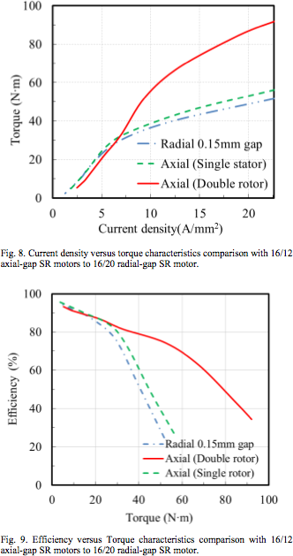 On looking over some of
this paper such as the graphs shown, it
becomes evident that the two rotor axial flux design is surely the "way
to go" for a switched reluctance over-a-horsepower power motor.
On looking over some of
this paper such as the graphs shown, it
becomes evident that the two rotor axial flux design is surely the "way
to go" for a switched reluctance over-a-horsepower power motor.
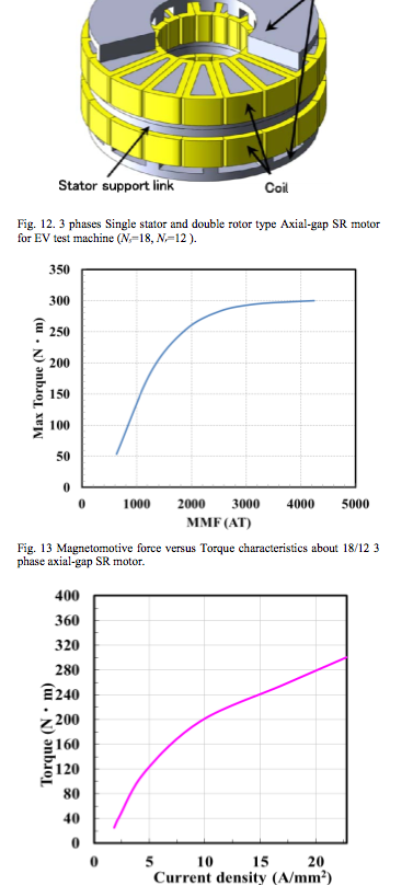 The Japanese
paper described two motors. The second one is the 3-phase AFSR motor of
12" diameter of which a model was actually built and tested. It was the
most interesting to me because it's near my size and parameters. It has
twice as many coils as I usually use, 18, with the sort of "co-linear"
shape of leading and trailing edges that I had identified as probably
having the most flux and hence the most torque per coil and per amp for
this type of motor. The 12 narrow rotor poles are substantially
different from my "lobes", partly in keeping with the narrow coil cores.
The Japanese
paper described two motors. The second one is the 3-phase AFSR motor of
12" diameter of which a model was actually built and tested. It was the
most interesting to me because it's near my size and parameters. It has
twice as many coils as I usually use, 18, with the sort of "co-linear"
shape of leading and trailing edges that I had identified as probably
having the most flux and hence the most torque per coil and per amp for
this type of motor. The 12 narrow rotor poles are substantially
different from my "lobes", partly in keeping with the narrow coil cores.
An interesting feature is the "Stator support link", which
apparently splits the coils in half, or at least the copper windings
(it's not really clear), but which must provide a means of fastening
the stator in the center of the motor, between the two rotors. The text
mentions it being related to the two rotors shrinking the tiny gap
owing to magnetic attractive force to the stator. (Once again this
model had no external shell - the rotors were the outside and the
stator connected to the stationary axle.)
Theoretically it would deliver up to 302N-m of torque,
which is just over 200 foot-pounds and should be adequate to run the
Chevy Sprint with no gear or belt reduction!
The motor said the motor had a speed of "up to 330RPM",
allowing a vehicle to achieve a speed of 30 Km/hr. This seems like an
absurdly low top speed for a motor with solid steel rotors. A test
graph showed up to 800 RPM, and with loss of torque with speed at very
low speeds. Of course, this depends also on the applied voltage and the
back EMF of the design, so it may be that the applied voltage could
easily be higher (or the number of turns in the coils reduced to lower
the back EMF), resulting in higher available speeds.
Since I already have the Chevy Sprint configured with a
transmission under the hood to which the motor could be attached, a 2
or 3 to 1 speed reduction could be obtained with a chain or belt drive
(to the original differential), giving more torque, with a higher speed
- up to about 2300 or 3500 RPM at 100Km/hr on the highway. Even if the
torque of the motor and controller I build don't attain those in the
paper, it would still have plenty of force.
I can see how all the little short segment, intense flux
transitions could deliver much more torque than the wide lobes of my
present design - over very narrow areas with rapid coil switchings per
RPM.
Maybe I'll concentrate on getting the first motor done and
working, and the controller working, and all installed on the outboard
using the present design, while I consider all these probably desirable
designs for larger car motors. I do have one or two reservations.
Foremost, their design seems to have a lot of torque ripple. Second,
the low RPM.s indicated, including rapid torque reduction with RPM,
must be the result of the rapid flux transitions from the narrow coils
and rotor poles. The high torque may come with the high torque ripple
'built in', and it may limit the available RPM, with high back EMF at
low speeds. I may still find the 9 coil, 6 rotor poles version has more
desirable characteristics. ...or maybe 12 coils and 8 rotor poles?
...or?... And maybe some rotor pole edge shaping to reduce torque
ripple, even at the expense of maximum torque. Doesn't the motor have
to start the car rolling even from its minimum torque positions? Better
to raise those. Or, I might change the pie slice coil shapes to
something more like diamonds or rectangles, which would be the same as
edge shaping and also would allow some air flow gaps across the coil
windings for cooling. (And rectangular pieces of steel would be easiest
to cut - assuming I can use solid soft magnetic steel instead of
laminates.)
Electric
Weel Motor (Generator)
Rick Linden of Pacific Coastal Geoscience, the designer
and builder of a floating river hydro power generator, came over on
several occasions and we
worked on finishing the Weel generator for the unit.
First we finished wiring up the stator coils. We wired it
as two sets of 4 coils in series per phase, which left 12 wires to hook
up, and it can be configured as 8 coils in series (higher voltage) or
two sets of 4 in series (higher current). The actual voltages and
currents will depend on RPM, and on the adjustment of the flux gap.
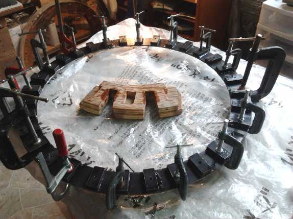 We epoxied the 32 magnets to the rotor's outer steel ring,
16 at a time in two separate sessions.
Since the rotor unit was too big to put in the oven, a day or more had
to be allowed after each operation for the epoxy to set. Before the
second session I made a jig to allow safely inserting the second set
magnets (north up) between the magnets of the first set (south up).
Once in place, each magnet was clamped down to ensure it wouldn't snap
over against one of its previously installed neighbors.
We epoxied the 32 magnets to the rotor's outer steel ring,
16 at a time in two separate sessions.
Since the rotor unit was too big to put in the oven, a day or more had
to be allowed after each operation for the epoxy to set. Before the
second session I made a jig to allow safely inserting the second set
magnets (north up) between the magnets of the first set (south up).
Once in place, each magnet was clamped down to ensure it wouldn't snap
over against one of its previously installed neighbors.
In a third session, we put the main lexan ring in and
wrapped the polypropylene strapping around the magnets and through the
slots in the rotor. This should ensure they're well attached and able
to take considerable centrifugal force. A 26" diameter magnet rotor is
an impressive looking rotor!
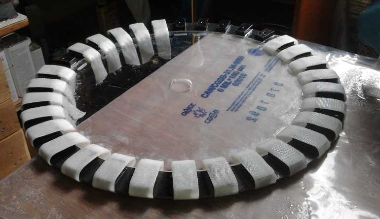 Epoxying on the PP strapping to secure the
magnets and the lexan rotor.
Epoxying on the PP strapping to secure the
magnets and the lexan rotor.
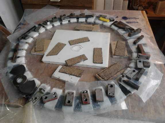
Aligning the lexan center height with the steel ring using spacers, and
weighing down the strapping to keep it in place while the epoxy sets.
The magnet side is down to keep the straps even against the plywood
with no protrusions.
The 'magnetized' rotor.
Lexan rotor reinforcing pieces are to be installed after the shaft is
keyed to ensure alignment.
The pull from the magnets
to the stator will of course be immense, probably getting up into the
"hazardous" range for fingers
even with the safety wall between the rotor and stator ensuring a
considerable flux gap. (I look
forward to getting all the details figured out for producing switched
reluctance machines, which won't have any permanent magnets to mount or
to fight with.)
At month's end the main things left were to machine the
dual key slot into the main shaft, and then to place the lexan
reinforcement pieces on the rotor and glue them with methylene
chloride. The shaft was to have been keyed elsewhere, but the machinist
was too busy so it didn't get done. Neither did I get to it. Thus it
sits, nearly finished. (We got it done on April 3rd.)
"Green" Electric Equipment Projects
Aquaponics
& LED Grow Lighting Project
LED Grow Lights
Early in the month one emitter in the white light made
with the LED emitters from dx.com started flickering. A couple of days
later it went out, and another in the same row started to flicker. The
next day it didn't work at all. This is a theoretical weak point of my
lights, that if one emitter of four or five in parallel quits, the same
current is pushed through the remaining emitters and so they work
harder. Still, the currents were under 1/2 the specified maximum, so
the four remaining emitters should have had no problem. I already
noted that the dx.com emitters had higher voltage drop and also weren't
as bright as other seemingly identical emitters I ordered from a
Chinese store on aliexpress.com. And the 10W dx.com LED "light bulbs"
probably made with the same emitters keep burning out and needing an
emitter replaced. While they run warmer than ideally in both lights, I
finally conclude they are just crappy emitters, to be avoided.
 On the 17th I
tried swapping the two LED grow lights, with
different wavelength blue (450nm) and violet (420nm) emitters. I keep
saying how my linear current current regulators are really efficient at
12 volts. But the violet one was now getting 13.65 volts from the solar
system instead of 12.0 volts from a power adapter, and soon the
transistor heatsink bar was quite hot. I measured the voltage across
the lights and it was just 9.75 volts - apparently the violet emitters
had somewhat less forward voltage drop (3.02v) than the blue ones
(3.23v). At 12 volts the supply efficiency would thus be just 81%. At
almost 14 volts the power transistor had about 4 volts across it and
was thus dissipating 6 watts extra in a 15 watt light, total 21 watts.
That's only 70% efficiency. That's probably tolerable since 14 volts
means the solar panels are working... but it runs too hot! Evidently I
could either have put an extra row of red LED.s in it for 11.65 volts,
or used 3 rows of violet emitters and just one of reds (10.85v).
On the 17th I
tried swapping the two LED grow lights, with
different wavelength blue (450nm) and violet (420nm) emitters. I keep
saying how my linear current current regulators are really efficient at
12 volts. But the violet one was now getting 13.65 volts from the solar
system instead of 12.0 volts from a power adapter, and soon the
transistor heatsink bar was quite hot. I measured the voltage across
the lights and it was just 9.75 volts - apparently the violet emitters
had somewhat less forward voltage drop (3.02v) than the blue ones
(3.23v). At 12 volts the supply efficiency would thus be just 81%. At
almost 14 volts the power transistor had about 4 volts across it and
was thus dissipating 6 watts extra in a 15 watt light, total 21 watts.
That's only 70% efficiency. That's probably tolerable since 14 volts
means the solar panels are working... but it runs too hot! Evidently I
could either have put an extra row of red LED.s in it for 11.65 volts,
or used 3 rows of violet emitters and just one of reds (10.85v).
But I'm starting to think that the real solution, for best
power supply and LED emitter voltages flexibility, is, after all, to
use a
switching regulator. It might probably be only about 85% efficient
where I - ideally - get up to 90% with the linear, but the "ideally" is
hard to get. The switching regulator would be good
at all supply voltages and with any combination of emitters I might put
in a light. And it would make 1/2 the heat of 70% efficient.
Tilapia Pool
 On the 3rd I
finally
decided that the tilapia pond would be a trench in the garden, made
with the rubber(?) pond liner. Weeds from the garden could be pulled
and thrown in, where the tilapia would hopefully eat them, reducing the
fish food
bill. And it was close enough to the greenhouse to pump water to and
from to flow through greenhouse plant beds. And more secure - easiest
to fence off from raccoons. I couldn't figure out where to put without
blocking a path until I thought of simply putting a bridge across the
trench. Tilapia like cover anyway. I dug out the outline of the trench,
not to full depth, and looked again the next morning to see if I
actually wanted it there. Wherever it was in the garden, it'd be
somewhat in the way.
On the 3rd I
finally
decided that the tilapia pond would be a trench in the garden, made
with the rubber(?) pond liner. Weeds from the garden could be pulled
and thrown in, where the tilapia would hopefully eat them, reducing the
fish food
bill. And it was close enough to the greenhouse to pump water to and
from to flow through greenhouse plant beds. And more secure - easiest
to fence off from raccoons. I couldn't figure out where to put without
blocking a path until I thought of simply putting a bridge across the
trench. Tilapia like cover anyway. I dug out the outline of the trench,
not to full depth, and looked again the next morning to see if I
actually wanted it there. Wherever it was in the garden, it'd be
somewhat in the way.
The trench
~18x22x76".
People were wondering who I was going to bury.
I don't think I've ever dug the garden down to the subsoil before!
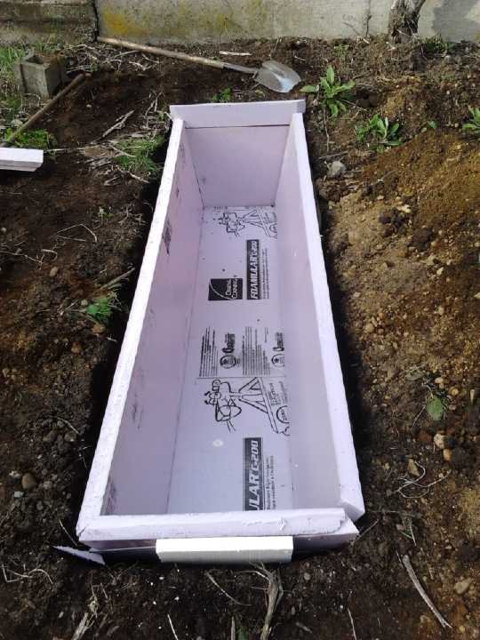 With it being
outside, I decided that the bottom and sides
should be insulated so it could be heated to extend the season, or
perhaps, with an insulated top cover, even be used all year. Fiberglass
was out, and the cost for styrene foam would add up. But not as much as
electricity cost to heat an uninsulated pond!
With it being
outside, I decided that the bottom and sides
should be insulated so it could be heated to extend the season, or
perhaps, with an insulated top cover, even be used all year. Fiberglass
was out, and the cost for styrene foam would add up. But not as much as
electricity cost to heat an uninsulated pond!
It took about 3 days to dig out the pond. Then I filled it
from drums of rain water, to about 95 imperial gallons, 115 US gallons
or 430 liters. This left a lip of about 6" to keep
fish from jumping out. Then somehow it took another few days to put a
concrete surround around it. The store ran out of concrete paving
blocks, and I ended up making some as well as buying some.
I saw small insects flying near the water and alighting on
it. I thought about breeding mosquitos. The water was too cold for
tilapia, barely 10 degrees C. I could either get a heater, allow
mosquitos to breed... or get some goldfish. I got 11 small ones,
"feeders" according to the pet shop. Then I got some more duckweed from
my brother's ponds. The goldfish won't eat it. It grows rapidly and I
can feed the surplus to the tilapia without having them make it
extinct. By the end of the month, the water was up to about 14°.
Theoretically tilpia wouldn't die, but it surely wouldn't be good for
them. Trout come to mind... So does hooking up the whole aquaponics
system in the greenhouse, including a small solar water heater Jim
Harrington gave me to help warm the water in the pond and system.
I'm not really clear just where I'm going here. Having dug
the pond, I worry about raccoons catching the fish if they're in it.
But the largest tilapia is almost 12" long, in a 12x12x12" aquarium
space, and will have to be moved somewhere soon. (There's always a 200
liter plastic drum with the top cut off, I suppose.) The one little
tilapia is now about 2-1/2".
I decided to use the big
swimming pool as a reservoir for
watering the garden in the summer, city water having become rather
costly. Someone said he had one and a seam split and all the water was
lost. So I don't want to invest too much in it that would be lost if
that happened, ie, valuable fish. I channeled water from my house roof
downspout and from my neighbor's garage roof. (It spills out of his
gutters and turns that end of my yard into a swamp. I put an open top
"barrel" with a hose tap at the bottom just across the fence to catch
it.) Just after it was set up to fill there was a great 36 hour deluge,
and it was 11" deep. With further March rains it got to 20" - probably
1500 imperial gallons. I suppose when I see inevitable mosquito
wrigglers I'll throw in some goldfish. Come to think of it, I could
surely put in some duckweed! (I did.)
Beans!?
I was about
ready to rip out the bean plants from the
aquaponics grow bed. They had grown as well as any pole beans in the
garden - better - but with no flowers it all seemed pretty useless. I
had added a bit of potassium chloride for potassium and trisodium
phosphate for phosphorus, but nothing was changing. On the morning of
the 16th there was one orange flower high up. This would have been most
welcome 2 months ago! Now it merely dampened my resolve to be done with
them and try other plants, that I had finally arrived at. The
flower shriveled in a couple of days, and no new ones appeared.
One thing the beans did appear to have done quite well was
their job of removing fish waste - ammonia that gets converted to
nitrates by bacterial action - and converting it to plant growth. The
water in the system stayed quite clear with little algae growth. (On
the other hand, the tilapia seem to eat at least some types of algae.)
Other than that, they're a bit of an odd ornamental house
plant!
Cordless
Lawnmower with NiMH "D" cell
batteries
Quite a while back Jim
Lawrence, the friend who helped me with my web site, had bought a
cordless lawnmower. These silly things use lead-acid batteries, which
of course don't last long. After he had bought replacement batteries
that only
seemed to last a year for not much less money than the original price
of the mower, I volunteered to replace them with 40 NiMH "D" cells.
(24V, 20AH.) The only part a bit tricky was the charging. On the
charger cord I put in a diode and a resistor to
drop the voltage a little from what the PbPb types took for charging.
Later as I learned how the fat copper straps I was using
would work loose with vibration, and how such 'battery packs' could be
dangerous with only the low-temperature plastic insulating the cells
from
each other, I "recalled" the mower and re-soldered it all with #16
stranded wire and tarpaper sheaths around the cells. Since then, the
only problem has been that a wire in the charger assembly came loose
once.
Now Jim has sent me a review on the mower with the NiMh
battery. (Yes, we were already mowing lawns here in Victoria BC in
February. We had no snow this winter - only a few frosts.)
Hi Craig:
Find attached a couple of photos of my electric lawnmower powered with
your metal-hydride batteries.
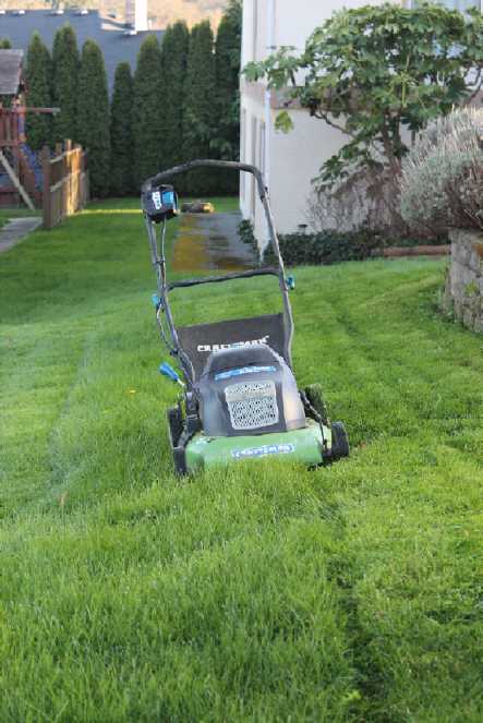 The pros are as follows:
1. Mower is super light in weight and easy to push around.
2. Batteries have been running around five years and seem as good as
new.
3. Needs no oil or gas.
4. No fumes or bad smells.
5. Quiet as a vacuum cleaner.
6. When turned over for cleaning, no fuels or oils drains out.
7. Always starts instantly.
8. Easily does my lawn and even the next door neighbours lawn on a
single charge.
9. Requires virtually no maintenance.
10. Unlike regular batteries, they are not toxic.
11. Inexpensive to power.
The cons are as follows:
1. The cutting blade still needs regular sharpening.
2. Needs a steady trickle charge to keep the batteries full.
Pro or Con?
1. Initial costs of batteries are high but after a few years costs
average out much better than any alternatives.
Hope this helps for your next review. Maybe you should start selling an
upgrade kit...$500 for potentially 10 to 15 years of use...good
investment.
Jim
Electricity Storage
Turquoise Battery
Making Project
Cylindrical Batteries?
Seeing I couldn't seem to stop the flat plate cell leaks,
apparently through the graphite foil, and that this was preventing me
from making batteries, I thought again of the carbon rods used in
standard dry cells. I started to wonder how it would work out if I made
batteries with "F" or "D" cell carbon rods, with similar construction
to simple standard dry cells?
Ideas started forming. I didn't see how I could reliably
jam things together under pressure without breaking the carbon rod and
ripping the separator sheets before it was together.
But there's the fact that the nickel oxides in the
positive side always expand. Perhaps if I made use of that I could make
things so they'd start with just enough play to set the layers in place
to put together the cell, and when water was added, it would swell and
everything would be a tight fit. This seems to be worth a try, given
that nothing else seems to have worked, and since it seems to work
somehow for billions of dry cells. Whether it would be a "dry cell"
(AKA starved or
limited electrolyte cell) or wet/flooded seems to be of little concern
at the
moment.
So the "layers" of the cell would start with the carbon
rod in the middle.
Surrounding that would be the fat posode cylinder of
nickel
manganate with carbon black. I'm not sure how the graphite felt could
be worked in since it would be compacted from one end, but perhaps I
could cut some strips or bits of it to throw in. This electrode would
be compacted inside a pipe, closed at the bottom and with a metal rod
just a trace fatter than the carbon rod. A die would push into the
pipe, filling the space between the center rod and the pipe. All these
would be much longer than the intended electrode in order that the
powder could be poured in and then compacted in one press.
Around that would be the separator, probably paper plus a
couple of layers of PP non-woven fabric, then more paper. But I'd try
different things to see how many layers were really necessary.
Surrounding that would be the negode of nickel and monel,
and perhaps more carbon black. This would be done the same way as the
posode but of course with larger diameters so it would fit around the
inner parts, just loosely enough to slip over the paper without trouble.
Finally would be a metal pipe, tube or can to hold it all
and form the negative terminal. (This got changed to a PVC pipe with
end cap, with a sealed bolt for a terminal.)
A plastic disk piece would fit the top and if necessary
the bottom. Perhaps the tube could be crimped on the ends over
this/these pieces. (Perhaps I could save the crimped metal terminal on
the
carbon rod from the original cell.)
Before crimping the top on (or before screwing in the
bolt?), electrolyte would be added.
This should cause the posode to swell and take up the slack spaces,
tightening around the carbon rod and pressing against the separator
layers.
Some thoughts... A Nickel-Zinc or Nickel-Nickel Acid Battery?
As I thought of configurations with a carbon rod electrode
in the center, I kept thinking of the rolled-up dry cell. Nickel-nickel
would be the obvious choice. The high voltage of nickel-manganese with
its bubbling
during charging would probably preclude such a tightly wrapped up
configuration. What would the current conductor layers be? The graphite
foil would crack if rolled, so that leaves the graphite foam and
flexible sheet graphite gasket material.
For the negative, the zinc sheet came to mind. But the
reaction voltage of zinc would have it oxidize before the nickel... it
would then be a nickel-zinc battery. Iron might be good; maybe
stainless steel mesh. Or perhaps the copper mesh. There'd be nothing to
stop the negative terminal from being metal - only the plus side has to
be carbon. Pieces for the negative could be tack welded together and to
the mesh. The carbon rod and a sealed metal rod for terminals would
allow for very minimal leakage of electrolyte. It could work.
But what about that zinc? A sheet of zinc works quite well
as an electrode. The trouble with zinc is that intermediate-state
soluble zincate ion that causes it to form dendrites, branching "roots"
of zinc during charge and discharge. This both corrodes away electrode
substance and tends to short out the cell.
This brought me back to a theoretical idea I had quite a
while back, and I made a demo cell just to show it could be done. The
reason lead is used for lead acid batteries, despite its high atomic
weight and consequent low energy per kilogram, is that lighter metals
would dissolve in the acid. I looked for an acid that wouldn't dissolve
zinc and nickel compounds. And I found one: oxalic acid. Neither
nickel, nickel oxalate, zinc nor zinc oxalate was soluble according to
a table. (The state of charged nickel, oxide, and its potential
solubility
might be a bit of a wild card, as well as the exact reaction voltages -
AFAIK this is pretty uncharted territory.)
Back then, I made a little test cell with a piece of
nickel hydroxide electrode from a Ni-Cd dry cell and a zinc rod to
illustrate the point. It worked but had little current and seemed to
deteriorate. The voltage dropped and charging didn't entirely restore
it. But it was open to the air in a beaker and the posode current
collector was made for pH 14, not pH 1, and would obviously
deteriorate. It was hardly a definitive test except for showing an
initial voltage of [IIRC] about 1.7 volts.
The likeliest nickel reaction (I think) would be something
like: Ni(COO)2 + 2e-
<=> Ni2(COO)2 + (COO)22−
.
Now the likely zinc reaction is: Zn +
(COO)22− <=> Zn(COO)2 + 2e- .
The environment is acidic and the
compound isn't ZnO or Zn(OH)2 . Will the zinc still form the
intermediate soluble zincate ion, or will the reaction go direct as
indicated above? The zincate ion is more usually associated with an
alkaline
environment. There have been a lot of people who've tried a lot of
different things to prevent zinc from growing dendrites in battery
reactions, but I don't think anyone has thought of this before.
To be honest, the thing I like about the zinc is simply
the ability to roll up a solid sheet of it in with some paper and a
nickel posode side, for a very simple and pretty high-current negode.
I'd just as happily roll up a thin sheet of nickel... if such a thing
could even be found for sale, much less afforded! Maybe I could use
nickel-brass, and the zinc would oxidize away. I actually have some of
that! (nickel-brass, AKA "nickel-silver", Cu:Zn:Ni , ~65:18:17%)
If the zinc doesn't work out and yet the nickel side does,
one could do a nickel-acid battery with with oxalic acid and nickel
compounds in both electrodes. In fact, that would be pretty much
identical to the nickel-nickel salt cell except for the electrolyte.
That brings me right back around to that cell. Except for the new idea
of
using the nickel-brass sheet.
Nickel-nickel (Salt) Cell with Nickel-Brass Sheet Negode
So a plan for a cell (wet or dry) is (a) the carbon rod from a standard
"F" (lantern battery) cell, (b) my "usual" nickel manganate electrode
as a cylinder packed around the carbon rod in a manner similar to
standard dry cells, (c) separator sheet(s) ringing this posode, (d) the
thin nickel-brass sheet as a ring around the outside of the paper, (e)
and finally a common 3/4" (or 1") x 3.5" long PVC water pipe around the
whole thing, with a PVC end cap glued to the bottom. (or a flat insert
that doesn't stick out and increase the diameter.)
For the top, I may be able to use the original top from
the "F" cell if it glues okay to the PVC. It'll need an extra hole near
one side for the negative terminal unless that terminal can be an
exposed piece of the outer ring, which could be soldered to directly.
That would have to have some glue all around it between it and the
outer pipe so nothing could leak. I have some misgivings about that,
but I don't like trying to tack weld on a terminal to the sheet, either.
The inner electrode would be as discussed at the top of
the 'storage' section. I'll elaborate on that when I go to make it.
To use a sheet containing nickel for an electrode as well
as the current collector would seem like folly except that I know it
works with zinc sheets. Standard dry cells are made that way. OTOH, the
amp-hours capacity from a simple sheet of zinc in the dry cell come
from the
fact that it's gradually eaten away, and it's not just the initial
surface that reacts. So I may make a cell or two this way, but some
powder material - monel - will have to be added to the sheet to give
real capacity. The layout might be a good one, tho. I wonder if there's
some way to "glue" the powder to the sheet metal so it holds together
during assembly?
To make porous nickel sheets and
porous nickel powder!
Another thought was that hopefully the zinc would migrate and
make some void spaces exposed to the electrolyte in the remaining
cupro-nickel. I wonder if one could leach out all the zinc to have a
porous electrode sheet somehow? Wikipedia verifies that HCl will leach
out zinc, forming ZnCl2, which is soluble. It might be preferable to do
this in advance of using the sheet. (Hmm, it looks like HCl might well
dissolve the nickel, too! Something else?)
That led to another idea, expanding on that... Edison's
technique for making thin nickel sheets was by electroplating nickel to
copper and then dissolving the copper with sulfuric acid... circuit
board etching
solutions also dissolve copper... and the way people separate gold
plating from copper is by dissolving the copper with H2O2 and HCl
solution. (That would
leach out copper, but again would probably also dissolve the nickel.
Ferric chloride might take only the copper, or the copper and zinc...
Must read up on this!)
Then, what about leaching out some of the copper
to make an atomically "rough" surface of nickel particles? That would
increase the exposed nickel surface and hence the amp-hours of the
sheet. This could be the subject of some experimentation. Ultimately
one could perhaps dissolve all the zinc and copper and be left
with relatively pure "porous nickel", which might make an excellent
electrode - or might disintegrate, or disintegrate as it oxidizes on
discharge. If pure porous nickel isn't good, there's probably some
optimum level of dissolving the copper that would make a conductive
substrate with a maximum of nickel exposed to the electrolyte.
Then, even a thin layer of monel powder somehow bonded to
that would make still more nickel surface area. Perhaps the monel
powder too should have some of its copper leached out to create more
nickel on the surface? Or even all of it to make porous nickel powder?
I wonder if there's some chemical means for bonding
or alloying the monel powder to the nickel-brass sheet? Or maybe just
torching it [with a flux?] to "sinter" them together? (With both(?)
pre-treated to
reduce copper and maximize nickel at the surface. That should make an
amazingly conductive electrode, with high exposure of the
microscopically porous nickel to the electrolyte yielding excellent
amp-hours per quantity of nickel. And it surely won't fall apart during
or
after insertion into the cell. That would be a real winner!
All these things should be experimented with! I'll
definitely make time for battery development work again.
I've never wanted to roll up sheet metal before. Now I
have two jobs wanting smoothly rolled sheet in a month. I suppose even
if I had a commercial sheet metal roller, it wouldn't roll into a 3/4"
diameter, and if it did, I wouldn't be able to get the rolled 'tube'
off the roller. I think I'll have to make something to do a smooth
rolling job.
Ideally I wish I could make nickel-brass pieces into
one-piece cans, having
sealed sides and bottom, with the top rim to be crimped around a
plastic lid (with the carbon rod in the center) to seal it all. That's
the real 'production' method. It ought to make everything a lot faster.
But stuffing a rolled up piece into a PVC pipe "can" might be easier
for home production.
Carbon/Graphite from Packaging 'Popcorn'/'Peanuts'
A friend sent me a link to an article about turning
packaging 'peanuts' or 'popcorn' into nano graphite forms with heat in
an oxygen-free atmosphere, 500-900°C. I could probably do it in the
mini kiln if I can keep the air out, ie, make a sealed container of
some sort that can take the heat. Maybe it could replace carbon black,
or graphite foam, depending how it comes out.
Packing peanuts
could be reused in better batteries

http://www.gizmag.com/packing-peanuts-battery-anodes/36681/?utm_source=Gizmag+Subscribers&utm_campaign=3f1fba0948-UA-2235360-4&utm_medium=email&utm_term=0_65b67362bd-3f1fba0948-89749090
<<
When a new lab was recently being set up at Purdue University in
Indiana, a lot of the equipment arrived in boxes full of protective
packing "peanuts." Unfortunately, few facilities exist for recycling
the little pieces of foam, so they typically end up sitting in (or
getting blown around) landfills for several decades. A team of Purdue
researchers, however, discovered that they could find use in
better-performing lithium-ion batteries.
When a lithium-ion battery is charging, the lithium ions are stored in
one of its two electrodes, known as the anode. Ordinarily, anodes are
made out of graphite. Led by Prof. Vilas Pol, the Purdue scientists
instead set out to create a new type of anode made from carbon.
They started by heating packing peanuts (which were made from
polystyrene or were starch-based) to a temperature of between 500 and
900 ºC (932 to 1,652 ºF). They did so in an inert atmosphere,
in either the presence or absence of a transition metal salt catalyst.
Depending on the peanut material and the approach taken, the result was
either carbon nanoparticles or carbon microsheets. In both cases, they
made excellent anodes.
This was partially because they were about one tenth the thickness of
graphite anodes, allowing for quicker charging times. Additionally,
they exhibited less electrical resistance than graphite. In more
precise terms, they demonstrated a maximum specific capacity of 420
mAh/g (milliamp hours per gram), as opposed to the theoretical 372
mAh/g maximum for graphite anodes.
What's more, the carbon anodes stood up to 300 charging cycles without
a significant loss in that capacity.
The microsheets were particularly effective, as their porous structure
allowed for more contact area between the anode and the battery's
ion-carrying liquid electrolyte. That said, the researchers are now
working on making them even more porous, to further enhance their
electrochemical performance.
According to Purdue, the packing peanut conversion process is
inexpensive, environmentally-friendly, and should be practical for
large-scale battery production.
Source:
<http://www.purdue.edu/newsroom/releases/2015/Q1/new-processing-technology-converts-packing-peanuts-to-battery-components.html>Purdue
University
>>
http://www.TurquoiseEnergy.com
Victoria BC Canada