Turquoise
Energy Ltd. News #87
covering April 2015 (posted May 3rd)
Victoria BC
by Craig Carmichael
www.TurquoiseEnergy.com
= www.ElectricCaik.com
= www.ElectricHubcap.com
= www.ElectricWeel.com
Month In Brief
(Project Summaries)
- NiNi cylindrical batteries - Axial Flux Switched Reluctance
Motor (AFSRM) - a spare Electric Caik motor - Electric Weel Hydro
Generator - RX7 EV Update: brake trouble - Paperwork for CRA -
Commercialization? - Lawnmower Motor, Generator for Windplant.
In Passing
(Miscellaneous topics, editorial comments & opinionated rants)
- How to Foster Sustainable Energy Product Development - False
Flag Terrorism - JADE HELM 15 [HELM = "Homeland Eradication of Local
Militants"!] - Uncovering the Collapse 2210 National
Geographic Documentary: Archeologists uncovering the
ruins of 20th century civilization - Human Evolution will Continue; a
glorious future lies ahead.
Electric Transport - Electric
Hubcap Motor Systems
* Electric Hubcap Axial Flux Switched Reluctance Motor (AFSRM)
* Variable Torque Converter Transmission
* Giant Electric Weel Generator
Other "Green"
Electric Equipment Projects
* Aquaponics update
Electricity Generation
(no reports)
Electricity Storage - Turquoise Battery
Project (NiMn, NiNi), etc.
* Improved nickel 'negodes' from cupro-nickel sheet, micro-fine nickel
flakes/powder, gum arabic - & Easier cylindrical cell assembly
* Cylindrical 'posode' compactor press
* Aluminum Ion DES Battery - "Moving Target" battery chemistries?
No Project Reports on: Magnet
motor,
Lambda ray collector, evacuated tube heat radiators, CNC
gardening/farming machine.
April in Brief
Negative Nickel Battery Electrode with Etched Cupro-nickel Sheet
and
Micro-fine Nickel Flake Powder
 In late March
I decided to try making nickel-nickel/salt solution batteries in the
form of standard dry cells with a carbon center rod from a "D" or "F"
cell. But how to get a
good outer negative electrode? Getting good conductivity from powders
has been somewhat elusive, and (unlike the dissolving zinc sheet of a
non-rechargeable dry cell) a simple sheet of nickel would give very
low amp-hours since only the very
surface of the nickel is accessible to the electrolyte.
In late March
I decided to try making nickel-nickel/salt solution batteries in the
form of standard dry cells with a carbon center rod from a "D" or "F"
cell. But how to get a
good outer negative electrode? Getting good conductivity from powders
has been somewhat elusive, and (unlike the dissolving zinc sheet of a
non-rechargeable dry cell) a simple sheet of nickel would give very
low amp-hours since only the very
surface of the nickel is accessible to the electrolyte.
On April first and second I conceived of making
'fractally' porous nickel 'negodes' by sintering monel powder to
nickel-brass* sheets, and then dissolving away the zinc and some of the
copper with ferric chloride, to leave nickel-rich surfaces that were
both finely porous from the sintered powder and microscopically porous
from the pits and channels formed by the missing zinc and copper atoms.
(The Wikimedia 'fractal brocolli' image shown has a vague
resemblance, illustrating how much surface area there can be on
a small surface.) The back of the sheet will be protected (unetched) to
retain
full conductivity and strength. I planned to use #28 gauge nickel-brass
and #300- monel powder, but later decided to order some monel sheet
metal, which I later changed to cupro-nickel ( Cu:Ni 70:30 - cheaper),
and some pure fine nickel powder as well. I discovered that
the available micro-flake nickel powder is so much finer than the
available monel
powder that the utilization of the nickel is bound to be far higher,
even without etching it.
It arrived on the 21st. The great increase in fineness and
surface area over the monel powder was obvious at 40x magnification.
"Short circuit" surface ohm meter readings confirmed that
this looks like a fantastic way to make a nickel 'negode'! It's about
the most exciting battery making idea I've had in some time. It should
make for very high nickel utilization in the electrode as well as very
high conductivity through it, to give high amp-hours by weight and high
amps per electrode interface area.
Add to that the simple dry cell construction idea! And
I've had the thought that since I can't make a cupro-nickel "can" or
even a
tube and will be rolling up sheets of cupro-nickel into tubes with an
open
seam, most advantageously, the seam can be spread apart during
assembly. Viz: The center pressed 'positrode' isn't that strong. It can
be wrapped with separator paper and the carbon rod inserted. Then the
slightly open outer sheet of cupro-nickel with nickel flake glued to
the
inside face can be slipped up around it with no friction, ensuring the
paper isn't ripped, the pressed 'posode' isn't broken, and the carbon
rod isn't cracked. Then as it's being inserted into the PVC pipe it
tightens around the inner part, but it's all inserted as a single unit.
Nothing has to slide against anything else except the solid metal sheet
against the pipe.
By the 29th I had all the materials. Now I need to find
time to work on it. Doing batteries is
deceptive. You mix the ingredients and make the cell by hand, which
itself takes time, but then it has to be charged and discharged and its
performance has to be monitored and charted for weeks (and hopefully
months) until it quits working or has demonstrated longevity. This saps
time and energy from every other project.
* Nickel-brass: AKA nickel-silver, AKA german-silver - Cu:Zn:Ni alloy
~65:17:18%.
( I can't bring myself to call it by any name with "silver" in
it as it contains no silver. )
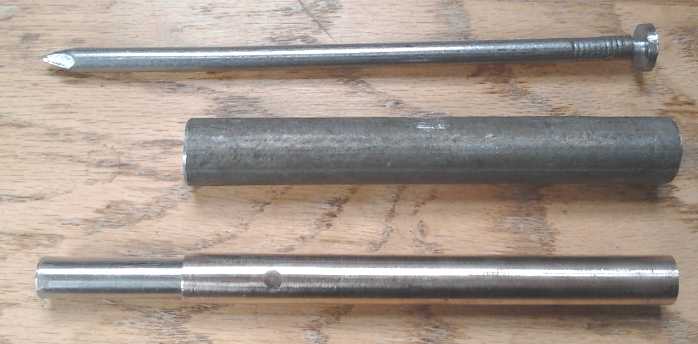 The Posode Compactor
top - spike for center hole for 8mm carbon rod
mid - outer body pipe, 17mm I.D. (O.D. of electrode)
bot - 2 telescoping pipes together 17mm O.D., 8mm I.D.,
to cram down the powder into a porous 'solid' with the hydraulic press.
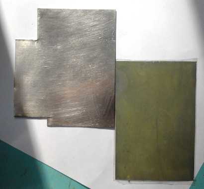
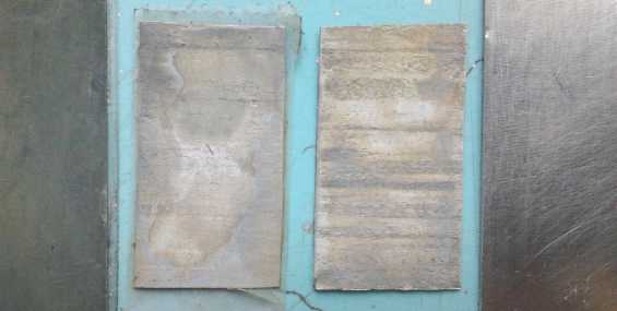 Nickel-brass surface etching experiments.
L: Etched in hydrogen peroxide and hydrochloric acid
C: two pieces etched slightly differently in ferric chloride
- these have rough 'grooves' at 40x magnification.
R: Regular (unetched) nickel-brass
Switched Reluctance Motor
On doing some reading I began to realize that the parts I
have
won't make the best switched
reluctance motor. The round cores
aren't the right shapes (straight edges) to work
into a really good design. Making it with solid chunks of steel rather
than "laminates" will limit the RPM severely with high losses as it
increases - and efficient high RPM is the very feature most wanted. But
where
to get laminates or some equivalent?
It looked like the most practical
way - if not the only practical way - to do a really good SRM would be
to buy soft magnetic iron powder and make my own magnetic forms to my
ideal specifications, by mixing it with epoxy and casting it into a
mold. Why would that not be the best, anyway?, at least on the stator
where there's no centrifugal force.
ChemicalStore.com had 100 pounds of "high
purity
soft magnetic iron
powder" (99.4% pure) for 800$US, made for "P/M" or resin casting,
my
intended
method.
(So
I'm
not
the
first
person
to
think of that after all!)
Looking it up, yes it needs to be high purity (to be good soft
magnetic): evidently it
was in fact exactly the right stuff! But could I please start a
little
smaller and cheaper? OTOH, the stuff's heavy; coil cores are heavy, a
substantial
part of a motor's weight. 100 pounds is only enough for a few motors!
(It's probably not even a very big bucket.) Hmm... special order,
non-stocked... "nobody wants under 100 pounds!" Shipped from the east
to the west coast and brought through customs. I bit the bullet and
ordered it. Withal it'd probably be 2000$C by the time I have it. But
after a couple of weeks it appeared they must have forgotten about the
order, and considering the price I decided maybe I'd let it lapse, and
try grinding some old iron sash weights to powder myself instead. Ugh!
That's what happens when you don't have a decent R & D budget...
you get sidetracked into doing things like grinding metal to powder.
Still, a little carborundum in the mix won't hurt, and perhaps an
automatic feeder can be devised so I can just leave it running.
It appears Everything has to be "just so" to get really
good
results with SRM.s. After studying and figuring out from the papers and
correspondence what will work
best, I abandoned the "should be about right" ideas and the present
"adapted from BLDC" construction. But the price of the iron powder is
imperiling the whole project. The lure of making a better motor
drives me on! Now I need to
come up with an exact design, and precision
manufacture it owing to the minuscule flux gaps. The CNC router will be
vital to shape and mold the parts and jigs, and it'll need exactly
aligned parts (adjustable?) with virtually no play in the bearings.
I came up with the idea to use large thrust bearings to
maintain the perfect alignment required for sub-millimetric gaps
between the stator and the rotor, and I ordered some 50mm x 70mm x 5mm.
There it sits for now, and having assigned some priority to making
batteries, finishing the variable torque converter transmission and
other things, it may be some time before I'm able to get going on it.
Spare(?) Electric Caik Motor
Having abandoned the unipolar motor idea, and as the SR
motor
looked more and more different in construction from the BLDC type,
there seemed to be
fewer and fewer parts on the Electric Caik motor that could
profitably be
used. I decided to set it aside to make a regular Caik bipolar BLDC
motor from.
All it needed to complete that were a hall sensor magnet sensor set,
some
modifications to the rotor, and re-assembly. The one thing it would
have over the old one (if I finish it) would be a rotor probably safe
for
3000 RPM instead of 2000, which would get the boat going faster. (In
fact, I could probably fix up the magnet strappings in the old one to
achieve that, too.) I fear it might still not be enough speed to get
the
motorboat up on a plane. 5000 or 6000 RPM with a SR motor would surely
do that - if the motor has the torque and power to get to that speed.
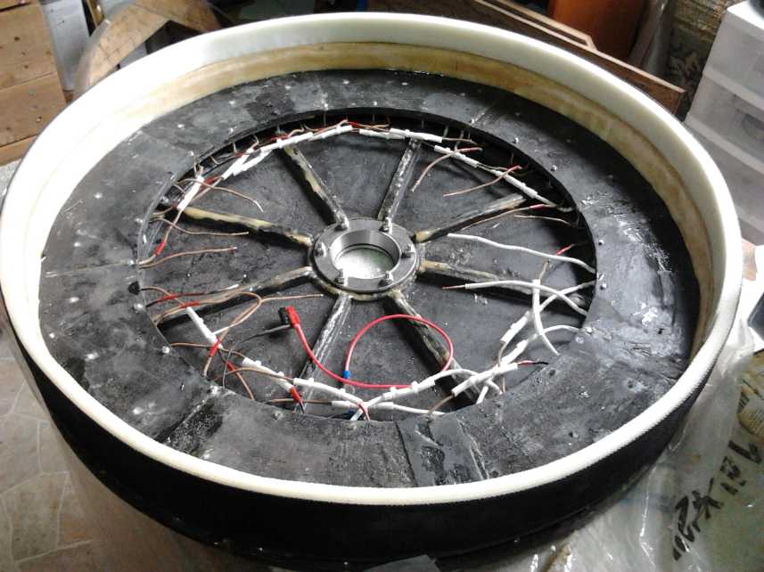
Giant Electric Weel Generator for Floating Hydro Power
Progress on this project consisted of trying to assemble
it and finding that I hadn't made it thick enough to accommodate the
bearing on the rotor end, and that the rotor wasn't stiff enough. It
assumed a "cupped" shape as the magnets wre attracted to the coil cores
all around the wide rim.
I built up the rotor compartment from 1.5" thick to 3"
with PP strapping and epoxy, switching theories from "why make it wider
than needed?" to "extra space is better than not enough!"
Then I made another reinforcing 'lexan' piece for the
rotor on the CNC router, doubling the thickness almost to the outer
edge. That should stiffen it up.
Finally some diodes are to be installed internally to
rectify the 3 phase AC to DC, with all 8 coils of each phase wired in
series, and then 'final' assembly. We'll see what voltage comes out in
operation at various "flow rates" ...with the pontoon mounted unit
towed behind a power boat to simulate river flow. (Linden's
idea for testing, which I think rather ingenious.)
On the 30th we spun the unit by hand. The voltages were
rather low with about 2.25 volts at about 60 RPM. This should rise
somewhat when the flux gap is reduced, and it can be geared according
to the desired voltage, but it looks like coils with more turns of
finer wire would probably have been better.
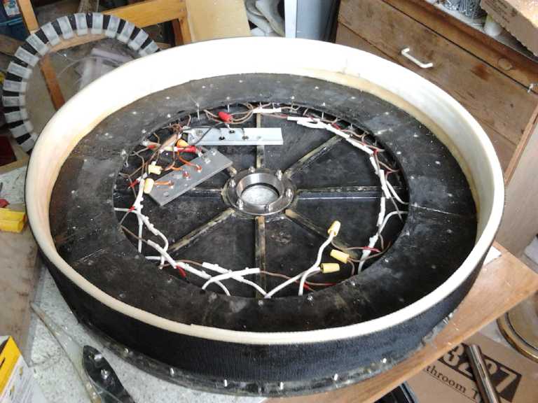 Electric Weel, coming together at last.
(Magnet rotor is on floor behind.)
Mazda RX7 EV update - brakes
For 2 or 3 months now the RX7 had been doing well, except
the hydraulic clutch (which I already repaired once) had been slipping
in various ways and making it hard to shift gears while moving. I found
if I didn't push it all the way down it worked better. The insurance on
my Tercel ran out on the 10th and I decided to save a few shekels and
not renew it until I definitely needed it, which was by the 30th. I
started to realize that if you're paying 60 $/month and only make 4
trips, that's 15 $/trip for insurance. Ugh!
On the 16th I drove the RX7 on a 10 mile round trip with a
2-1/2 hour charge at the far end. (That should have been just enough to
get home with a small margin. It would take over 24 hours to fully
recharge from this trip. This is where the gentle slow float charge
system sucks!)
Half way to the destination, someone turned
left right across my path and I had to brake very hard. (The smell of
burning rubber lingered in the car for 2 or 3 blocks.) Then it seemed
to be using more
power and the batteries were getting quite low by the time I was home.
It used 20 amp-hours total where on the previous trip to the same place
it was only about 16. I was somewhat puzzled, but didn't think much of
it. However, the next time I drove I noticed it didn't roll freely in a
parking lot, and when I got home I felt the wheels, and the right rear
was quite hot, after just a short trip. The left rear was cold. I took
the right wheel apart and found the brake cylinder was seized. It had
doubtless been seized since before I bought the car, same as all the
other seized things on it. I took it out and put it in a vise, but I
couldn't budge either end, and finally munched and broke the ends
trying. This probably explains why the car pulled to
the left some in strong braking from street speeds. The super hard stop
had evidently caused something to tighten up and jam the brake somewhat
on.
(Great, just when I had no other car to drive to an auto parts store!)
A store ordered in a new cylinder for the next day, so I
picked it up then. Usually I don't spend a long time doing brakes, but
on this one somehow nothing went together quite right or easily and I
spent several hours on it. I couldn't seem to adjust it both for smooth
travel and having the parking brake work well. I wasn't sure I wanted
to
park on much of a hill when there's nothing but the parking brakes
holding the car. Yet I can hear it rubbing on turns. On driving it a
while, I found that the car doesn't pull to the left in braking any
more, and the parking brake seems 'adequate' - about as good as it was.
I checked the other rear wheel while I was at it. The
shoes were good and it seemed fine. I wonder if maybe the front ones
might be rubbing just a little... they're at least warm to the touch
after any trip. Economy will be better if they're not rubbing! But I
didn't find time to take off wheels and check them.
Aquaponics & LED Lighting Progress
It's spring and I should be moving the operations out to
the greenhouse, but in fact I haven't had time to do much more than
feed the fish. After ripping down the masses of beanless pole beans and
their roots from the drain-down bed, I planted spinach, which didn't
sprout. Near the end of the month I planted a couple of lettuce
seedlings that were already planted. The light coming in the window is
steeper as summer approaches and they aren't getting any sun, so I have
an LED plant light on over them. They don't seem to be growing much so
far. There are just two tilapia in the system, so they only produce so
much waste/nutrient.
The largest tilapia in the aquarium is about 13" long now
and only fits in diagonally. I'll have to do something soon. For a bit
I thought she had some more eggs, but it wasn't true. I don't know if
they'll breed with a grill between the fish, but the female attacks the
smaller two, and they fight each other, if any of them are freely in
the same space. The one was attacked and killed by the other two in the
aquaponic space a couple of months ago. (I don't remember seeing this
aggressive behavior in the videos!) The guy I got the fish from used
200 liter plastic drums with the tops sawn off for tilapia tanks. This
should be good as the fish grow and I'm trying to get more of them...
but how do I keep the ever fighting fish separated? The goldfish in the
pond outside are much more peaceable. The small tilapia is now about 4"
long and still growing fast.
Paperwork!
I spent some days here and there sourcing and ordering
supplies, which were costly but necessary or at least highly desirable
for SR motors and for nickel battery 'negatrodes'. And I finally
started in on but didn't finish my annual reports for Canada Revenue
Agency on the
9th. (I should have had those done or at least well underway in March,
but the exciting developments in SR motors and the plans for producing
batteries seemed too good to put aside for mundane paperwork.)
Commercialization
I saw a news article about a company now offering smaller
loans in Canada to startup businesses, and how many banks were talking
about how technology was changing the finance 'industry', and how they
wanted to get in on it. "Silicon Valley is coming." said Jamie Dimon.
On a whim I called RBC, whose CEO had been quoted in the article. They
do 'smaller' loans (under 150000$), and one can leverage up one's own
money up to tenfold if accepted for a government guaranteed loan. This
is interesting. Of course I would want to have proven products and
pretty sure customers for them before I start in on such a thing. The
Electric Hubcap and Electric Caik motors are candidates, but they need
to be properly tested to the max to verify the great specs they seem to
have, and that they are strong enough physically to handle whatever's
thrown at them. The 12/120 volt LED lights, both flat panel and globe,
need a little redesign as I say with a switching power supply. The life
span of peltier modules for fridges seems disappointing, and more work
on the controls and variable voltage DC to DC supply is needed to make
the fridges a real product, plus of course a mold in which to cast the
expanding foam. Successful evacuated tube radiators would be valuable
for fridges. CAT plugs and sockets are just incidentals unless
injection molding and mass distribution are attempted. The NiNi
batteries could be an exciting product -- or selling of franchising the
battery making equipment and supplies. A working battery model will of
course be required.
In short, some things are almost there, but none are really ready.
OTOH, to hire a small crew to work as a 'development and production
team' could get everything moving along much faster.
Generator for Windplant
I think occasionally about making the vertical axis turbine (VAWT), and
occasionally I look for a cheap used lawnmower on usedvictoria.com to
take
the 120V DC permanent magnet motor out of. I've mentioned in a previous
issue how these motors seem like almost ideal DC generators for
such projects. While the mowers plug into a 120VAC outlet, there is a
little square bridge rectifier on the motor that converts the AC to DC.
They put out lower DC voltages at lower speeds. With the motor
disconnected from the switch, you can spin the blade by hand (careful!)
and see notable voltages generated, 10 or 20 or more depending on your
spin. (Of course I think the AFSRM would be even an even better
generator, but I have yet to make one, and the labor would be
prohibitive to make one just for a small windplant.)
Per a TE News a while back, I tested a 24 volt cordless
mower motor I had as a prospective windplant generator, but I found
both the voltage and potential power were pretty low. It might put out
50 watts. The most powerful plug-in mower is 120V @ 12 amps or 1440
watts, about 2 HP. I'll need to experiment to see what it'll do as a
generator, but it'll be far more than 50 watts. Hence my rather casual,
intermittent search for a cheap plug-in mower.
On the 25th I looked, and I found an ad from the 18th, a
moving sale with several
items "Must Go Today!" I phoned anyway, and found the person still had
the mower and was relatively close, but would be vacating the premises
within the next two hours. Just in time! I picked up the mower for just
40$. It was 120VDC, 12 A, the most powerful type. The mower seemed too
good to scrap just for the motor, and I tried it out by mowing much of
my overgrowing lawn with it. Anyway it's one less thing I'll need
assuming I do the VAWT some time.
In Passing
(Miscellaneous topics, editorial comments & opinionated rants)
How
to
Foster
Sustainable
Energy
Product
Development
by Craig Carmichael - April 2014
Sustainable Development Technology Canada (SDTC) sent out
an e-mail saying they were now "accepting applications" for their next
round of renewable energy project funding. I replied immediately, and
said (not very diplomatically) that they seemed more interested in
running a funding lottery, in handing out many millions to a few
(instead of working money to many), than they were in accomplishing
Canada's sustainable energy goals. I feel that they have set no goals,
and I said that they would do the taxpayer a service by shutting down
if they couldn't figure out a way to foster renewable energy prototypes
and support those actually working on them, which I understood was
their mandate from Parliament.
I pointed out that in their funding seminar in Victoria
last fall, the room contained a number of talented individuals trying
to create renewable energy or energy saving designs by themselves and
funded out of their own pockets, since they couldn't get funding
anywhere. (...besides SR & ED tax credits.) Virtually none of them
had a ghost of a chance of being
funded by SDTC. They and their fine ideas are left out in the cold.
Thus the SDTC hasn't even begun to fill the "funding gap" that was the
reason for its formation in the first place.
 This chart is from SDTC's own website (copied
2008), when
they pointed out the
This chart is from SDTC's own website (copied
2008), when
they pointed out the
virtually unfunded area the organization had been formed by the Canadian
government to fill: Technology development and Demonstration.
The dysfunctionality of the arrangements is apparent when
one considers that the reason SDTC was formed was that there was
essentially no funding available for the prototyping stage of new
product development. Yet SDTC presently says it will only fund up to
1/3 of the required budget. Where is the other 2/3 supposed to come
from? Isn't that the whole problem in the first place?
Furthermore, it now insists that a prototype be already
built, that "a consortium of companies" must make the application, and
that "customers for the products" be already involved! Thus they are
now funding "product commercialization" and even "market entry" rather
than "technology development", which is not their mandate and for which
there is other funding. And those stages involve major capital funding.
Technology development and prototypes are very low cost by comparison -
in fact, it seems to me that most prototypes today are funded by
individuals, and if an individual can't do it, the technology usually
goes
undeveloped. This seems to be where many sustainable energy
technologies are today. Nowhere. Where is SDTC?
I pointed out that I myself had given the presenter a
hastily drawn sketch for seemingly the most foolproof, simple, cheap,
and safe ocean wave power generator design ever (I am familiar with a
number of designs), one that could save the taxpayer 4 billion
dollars compared to Site C dam, or the power could provide additional
export revenue to the government. It had been in my mind for some time.
When I first saw it drawn in concept I thought it looked silly, but it
soon dawned on me that it was the wave power embodiment of the KISS
principle: "Keep It Simple, Stupid!"
The west coast of Vancouver Island is some of the best coastline in the
world for it. And I had heard nothing, which seems to imply there was
no interest in it. Where had it gone - into the garbage because it
wasn't done up on a computer as a glossy brochure, and showed some
technical workings instead of glib generalities?
It's not a far-fetched exotic plan with untried
technologies for some vague distant future. Environmental impact is
trivial
and even then easily reversible. Contracts could be let to build today
using existing technology and existing Canadian companies, one
installation at a time, which would then come on line perhaps within
weeks of each other to expand capacity as desired. How could this not
be right in line with SDTC's main sustainable energy technology goals
-- unless it is adrift in its own bureaucratic red tape and has no
goals?
But what's a positive alternative? Well, why has it been
that in times
of war or threatening war, such as when world war two and the invasion
of Britain was looming, miracles can be
accomplished like the invention of sonar, radar, the digital computer
and
(ugh!) the atomic bomb, but in peacetime, vital new ideas presented by
the inventive meet with pessimism and glazed-over, uncomprehending or
unsympathetic eyes by all administrations and agencies, and we can't
even get off oil in a century with solutions all around, staring us in
the face? Why are our societies unable to adapt and grow, even when
billions of dollars may be ineffectually thrown at the problems - or at
least at some of the symptoms?
As I view it, the only really 'great' technical
accomplishments since World War Two that weren't done by a single
person or two (besides the gradual evolution of electronics and
computing - no small things to be sure), were the original American and
Soviet
space programs, now half a century ago, and the creation of the
internet.
What was a common thread in all the above major inventive
technological achievements? It wasn't war! In all these cases the
applicable top inventive talent was hired and brought together into a
team. In small inventive teams, the possibilities go up almost with the
square of the number of engaged people as the ideas of one multiply
with those of the others, and one inferior idea (that can be a
stumbling block for an individual working alone) is discarded when
better
ones emerge. It gets results! Things that were previously thought
impossible get built. Progress is made.
It appears to me that the procedure to get actual
sustainable technology things built, working and employed or
commercialized, would be for SDTC (or some non dysfunctional
organization that might replace it) to peruse the possibilities and
decide first what things it wants to attempt to accomplish. Set goals
before all else! Then subordinate the "noise" to working towards
the goals.
The list of desired "sustainable technology development"
objectives might include, for example,
ocean wave power, floating or otherwise 'benign' river hydro power,
improved electric transport drives and batteries, "free energy" (lambda
ray collectors and magnet motors)... It could be short or long
depending on what people suggest and what is liked, and some items
would have much higher levels of funding and priority depending on
their immediacy, potential, seeming feasibility and (eg) whether
there's a social return, as there should be quickly with wave power to
generate revenue and hence tax reductions.
Then, collect applicant resumés. Find Canada's most
talented inventors, our innovative leaders. Seek them directly as
individuals, not as members of
contrived corporate entities. Find out what field they are in and
what they are interested in trying to accomplish, and sort them to
match them up to the desired goals.
Then interview them. What have you done previously? What
have you designed and built? Were you technically successful? Was there
commercial success or adoption? What were the factors that went into
success or failure? What are you most interested in doing now? How
would you proceed if given the opportunity? And personal details of
course: Where do you live? What if you would need to relocate for the
project? etc, etc.
Then hire the chosen, freeing them to put their talents to
work
instead of having them wonder where their rent will come from and how
to find the parts they need scrounging in scrap yards -- or maybe
having them
divert their efforts for months writing up futile funding applications,
complete with contrived "business plans" for their still unbuilt
technology,
or to go get an unrelated job
and abandon their project. Put together teams of talented people with
complementary skills related to the project, and incorporate the
project, or otherwise organize it. Rarely if ever is there an existing
bonafide organization to bring inventors together to pursue a new idea
- they need to be brought together by SDTC or other agency if the goal
is to be
accomplished.
That's how the great things done under the threat or
pressure of war were accomplished.
It's how the Apollo space rocket that took men to the moon
was done.
It's also how Xerox Parc Pacific was done -- the place
where the internet, e-mail and the world wide web, and all the original
structures behind them (IP, ARP, FTP, SMTP, HTTP, ...) were invented
and programmed. (And BTW the GUI too!) Without it, the internet as we
know it wouldn't exist.
And there were administrators with purse strings behind
all of these too, who said "Okay, let's do it!" - often the leader of
the country; others are less well known.
A couple of examples: Most authorities were skeptical
when a technician told a high level meeting that the Germans were
developing
electronic bomb targeting systems, and were inclined to reject the
idea. This is the same resistance most inventors with ideas meet, the
"normalcy bias" that things don't change. Winston Churchill said "Well,
lets
assume they are just in case" and had a team put together to develop
timely countermeasures - a tiny investment which played no small part
in deflecting much of the German nighttime bombing of Britain over the
winter of 1940-41 into empty fields. [Churchill, The Second World
War - Vol.2, Their Finest Hour - Book 2, Alone
- Chapter 4, The Wizard War] (This was among many other things that
were
invented or brought into production and use at this brilliant man's
instigation, eg,
from the first unemployment insurance and the battle tank before 1918,
to the main allied war strategies, and the "Mulberry Harbors" that
allowed the invasion of Europe from Normandy where there were no supply
ports in 1944.)
Harrison Storms gambled his career by hiring the all best
talent he could find from across America and put everyone together in
one building without telling anyone their role, to design the Apollo
capsule and the 2nd stage rocket. [Harrison Storms and the Race to
the Moon - a book well worth reading!]
Then ensure that the new sustainable sources of energy and
more effective means of using it will come into common use by making
them into social projects, locating and pursuing appropriate
partnerships or manufacturing, or even helping to fund the project
entities as profitable "subsidiaries" of the department (making the
department itself sustainable), with dedicated and capable prospective
entrepreneurs. But I'm just throwing around these utilization ideas.
Each
individual case, project and technology would be different. One can't
just expect automatic industrial or commercial adoption of some things
no matter how valuable - especially in North America, with western
industry now so emaciated. Ocean wave power, like hydro dam power,
pretty much has to be a publicly controlled project in most situations.
Floating hydro power units could be commodities, bought and sold to
serve various remote or low power utilization situations by rivers and
streams. Larger scale river sites might be licensed and taxed if it
seems necessary and warranted, or be publicly controlled. (Eg, by the
applicable public power utility.) EV batteries and drive systems are of
course items for manufacture and sale. Sustainable energy projects and
products appropriately and successfully adopted have lasting benefit to
society and to the environment.
[Also (not a trivial point!): Don't patent unless SDTC is to control
the patents and licensing terms on behalf of the inventors and in the
public interest until they expire. Valuable patents are almost
invariably acquired (one way or another!) by wealthy vested interests -
those already making and selling old technology products - in order to
prevent anyone and everyone from producing and commercializing superior
new
technologies that would compete and drive them out of business.]
False Flag Terrorism
The RCMP claimed to have thwarted a "terrorist attack" at
the BC legislature on July 1st 2013. It was to have been done using
pressure cooker bombs like the Boston Marathon bombing. Soon all over
youtube, freelance reporters were saying it sounded like a "false flag"
operation -- a violent event perpetrated by a government, often against
its own citizens, in order to attempt to swing public opinion over to
support something they wouldn't ordinarily be prepared to support, such
as curtailment of citizens' own rights or foreign war.
There are many known or highly suspect such incidents used
to justify war or other high-handed government actions throughout
history. For example, within the last 100 years:
* Poland "attacked Germany", a staged event an hour or two before the
German army rolled over the Polish border to start World War Two.
* The "Gulf of Tonkin incident" that started the Vietnam war is said to
have never happened.
* "Operation Northwoods" (1960?), a plan released after 50 years under
the freedom of information act, was to have an American spy plane "shot
down over Cuba", to "justify" to the American public a full scale
American invasion of Cuba. (JF Kennedy vetoed it.)
* The fall of the three World Trade Center towers in 2001 (only two of
which were hit by airplanes, and which looked to all appearances like
controlled building demolitions), is now commonly thought to have been
an inside job, and there is plenty of evidence to support this view.
With surprising speed if that were not the case, this event was used to
effectively suspend the US constitution and bill of
rights (not in so many words, to be sure!), and to justify any war the
president wanted to start.
* There was never any evidence that Iraq under Saddam Hussein had
"weapons of mass destruction", or that Iraq was involved in the World
Trade Center event. Yet it was invaded and conquered. (And as with all
previous invasions of Iraq since World War One, we were assured "It's
not about the oil.")
* There are a number of suspicious aspects to the Boston Marathon
Bombing and the astonishingly heavy-handed 'response' by at-the-ready
government forces, as well as to other recent well publicized violent
events such as the Sandy Hook shooting, the Canadian Parliament
"terrorist" shooting, the "terrorist shooting" in France, and the
murder of a Russian opposition leader of little note (presumably in a
pathetic attempt to cast suspicion on Vladimir Putin).
Finally the case went to trial this month. There was a
months-long
"sting" operation involving (ahem!) more than 240 police officers.
Video was
shown of the defendant (who was set up by an officer posing as an "Al
Queda liason" in a protected hotel room in Kelowna, BC) being berated
for not proceeding vigorously enough with the terror plot, with the
officer trying to guide him towards a "more realistic" plot instead of
a vague fantasy, and at the BC legislature instead of at a strip club,
on a ferry to Washington state, or in a shopping mall mens' room.
[source: Victoria Times-Colonist newspaper, April 9 2015]
So it has every appearance of authorities having (one more
time!) dragged some doubtless malcontented patsy off the street and
turning his vague discontented vengeful fantasies into a plot to be
"uncovered" and thwarted - or enacted - to scare the public into
acquiescing to whatever the government wants - which appears to be to
interfere more and more in everyones' affairs, strip away rights and
freedoms, and to engage in - or contribute to - wars of aggression at
the citizens' expense wherever they please.
NO MORE WARS!
NO MORE WARS!
NO MORE WARS!
This means you too, Canada! What on Earth are we doing in Iraq, Syria
and
Ukraine!?! Shame! France gave up trying to run Syria many decades ago.
And how
does it relate to Bill C51, the invasion of Canada and elimination of
Canadians' rights -- by Canada? Or should I call it the hijacking of
the
government and the nation? And to what end?
Hmm... Military Exercise JADE HELM 15, to be run throughout a
number US states...
(AllAcronyms.com)
JADE: Joint Assistant for Development and Execution
HELM: Homeland Eradication of Local Militants
"Most civilians won't see much." But are we going to see
the alternative media channels such as infowars.com in Austin Texas
violently shut down, with all perceived critics of Washington and its
propaganda "eradicated", treated as hostile "militants"? Like Hitler's
"night of the long knives"? Why are they laughing at the governor of
Texas instead of trying to reassure and to calm growing public fears,
concerns, and confusion, by telling everyone what on Earth the whole
thing is all about? If it's all innocent, why does the president not
explain it and reassure the public that rumors the closed "for plumbing
repairs" - and heavily guarded - Wallmart stores will be military
supply depots, and that it's to be a rehearsal for martial law or even
the start of it, are baseless?
It's been said that the territory is "similar to
operations areas overseas", but if so, why is homeland
in the "HELM" acronym? And why did one military commander mention
"constitutionalists" and "well armed people" as enemies or targets?
That pretty specifically says "Americans". Did he not take an oath to
uphold the constitution himself when he signed on?
If it's not the beginning of martial law, it certainly
looks a full dress rehearsal for it. (Why is it in the states where a
severe and protracted drought has been for several years, with
California, home to 38 million people, about ready to turn into
inhospitable desert? And why does the jet stream now veer north of this
region, and is that related to the heavy "chem trail" spaying off the
California coast?)
An equivalent exercise, "Maple Resolve", is evidently
being run in Canada, and someone videoed a trainload of armored
military vehicles headed west through Manitoba or Saskatchewan. I've
haven't heard much about it so far - but there's doubtless more info on
youtube.
 JADE HELM Map, showing supposed 'affiliation'
of states said to be involved.
JADE HELM Map, showing supposed 'affiliation'
of states said to be involved.
See youtube for a fuller view of what various people
think the agenda and specifics may be.
I watched an interesting 2010 video from National
Geographic (on youtube) called something like "Uncovering the Collapse
- 2210". (That's probably not quite it, but it should serve to find
it.) In it archeologists in 2210 are digging up ruins of 20th century
civilization to determine what happened to it. It goes over previous
collapses of civilizations and compares them with where we are now. It
gives a number of reasons that we might have a sudden collapse into
chaos with tremendous loss of life, as has happened a least a few times
in the past. Overpopulation is always a key, but usually unrecognized,
factor. The difference today is everything's global. Any and all of the
factors mentioned are likely to come into play in the relatively near
future.
A Glorious Future for the Earth
"Do you not realize that the hope of a better nation — or a better
world — is bound up in the progress and enlightenment of the
individual?" - Jesus [per The Urantia Book 145:2.8]
Evidently there is an unfolding cosmic plan for the
progress and uplift of this planet: Just the last 300 years have seen
an explosion of scientific knowledge and technology. The next few
hundred will focus on the moral, philosophical and spiritual evolution
of the individual, to eventually encompass the world. The uplifting of
consciousness that has already begun is just the beginning, and among
the people of today are the early pioneers. Humanity will continue to
evolve - not smoothly to be sure but as the overall trend - toward
sustainable living and sustainable societies, peace and co-operation,
cleansing and improvement of the genetic pool, better and longer lives,
utopia and light and life. In spite of the present short term trend and
the forecast for some horrific events, it won't finally degenerate into
confusion, evil, ugliness, overall environmental ruin and extinction.
Newsletters Index/Highlights: http://www.TurquoiseEnergy.com/news/index.html
Construction Manuals and information:
- Electric Hubcap Family Motors - Turquoise Motor Controllers
- Preliminary Ni-Mn, Ni-Ni Battery Making book
Products Catalog:
- Electric Hubcap 7.2 KW BLDC Pancake Motor Kit
- Electric
Caik 4.8 KW BLDC Pancake Motor Kit
- NiMH Handy Battery Sticks, 12v battery trays & Dry
Cells (cheapest NiMH
prices in Victoria BC)
- LED Light Fixtures
(Will accept BITCOIN digital currency)
...all at: http://www.TurquoiseEnergy.com/
(orders: e-mail craig@saers.com)
Daily
Log
(time accounting, mainly for CRA - SR & ED assessment purposes)
1-2: Writing February newsletter/report (#85); New concept for nickel
negative battery electrode (ideas & one experiment).
3: Continuation of electrode ideas; Finished February newsletter;
correspondence with AFSR motor specialist at U of Guelph for feedback
& ideas.
4: Continuation of Ni 'negode' ideas, with more experiments.
5: Cut and rolled steel rings for SR motor coil "cups".
6: Found monel sheet metal on web for said electrodes, wrote for quote
on 6000 square inches of .018" thickness. Bought "gum arabic solution".
Painted some onto etched nickel-brass test sheet and added monel powder
to it. Allowed to dry.
7: Torched test piece, inspected @ 40x. Several more experiments as
recorded below.
8: Corresponding with SRM expert Worked on big Electric Weel generator,
fitting parts together.
9: Epoxied 3" strapping to extend height (thickness) of rotor
compartment of Weel because the center assembly and bearing took more
room than
planned for.
10: Added 1/2 of epoxy rim spiral to Weel
11: Cut non-productive beans from aquaponics grow bed. Added most of
the other 1/2 of the rim to Weel. Found, sized & cut 2 pipes to
form & press NiNi battery positive electrode.
12: Ordered pure micro nickel flake/powder; looked for monel sheet
13: Finished electrode press (machined one of the pipes and end of
'spike' to fit together); SR & ED 2014 paperwork
14: Started machining bushing to adapt 1" shaft & 1.064" gear for
transmission; Started design/layout of AFRSM; SR & ED 2014
paperwork; monel sheet quote too costly - started searching for
cupro-nickel 70%:30%.
15: Machining matching 'shim' for 1" motor shaft to 1-1/16" I.D. gear.
16: Found a company (NEAlloys.com) selling Cu-Ni 70-30 and ordered some.
17: Did some tax/SR&ED paperwork.
18: Completed Electric Weel height extension with final layers of
PP-epoxy. Finished machining of shaft adapter for Electric Hubcap
transmission gear. Tried to put it on the shaft as a "pressed fit", but
it wouldn't go readily - didn't finish.
19: Straightened out adapter and pressed it on, with the gear, as a
completely pressed fit unit, using 9 tons pressure in hydraulic press.
20: Paperwork for CRA. Started Mazda RX7 EV Brake repair.
21: Got brake hydraulic cylinder, finished RX7 EV brake repair (ugh!)
22: -
23: -
24: Made additional reinforcement layer/piece for Electric Weel rotor,
which was too flexible.
25: Purchased a used electric lawnmower (120V, 12A) for use as a
generator for a windplant.
26: CRA paperwork
27: Installed/glued new rotor piece onto Electric Weel
28: Pressed diodes into aluminum blocks & wired Electric Weel to
output maximum DC voltage.
29: Finished installing diode assemblies in Electric Weel, made new
shaft keys (needed longer). (Order of Cupro-Nickel for battery making
arrived.)
30: Fitted together Electric Weel components. ("Teething" problems
remain. Some re-working was done May 1st.)
Electric Hubcap Motor Systems - Electric Transport
Electric
Hubcap
Size Axial Flux Switched
Reluctance Motor (AFSRM)
 At the start
of the month I cut steel rings to go around 6 coils for the "Adapted
Electric Caik" SR motor.
At the start
of the month I cut steel rings to go around 6 coils for the "Adapted
Electric Caik" SR motor.
But in reading technical papers and in conversation with
the
author of the U of Guelph paper, it became clear that while one might
build an AFSR motor of similar dimensions to a BLDC permanent magnet
motor, the requirements were so different that an entirely new design
was needed. The Electric Caik version would doubtless run, but it could
only be a demo unit, not a real workhorse.
In order to strike at the
main objective, I decided to
design the Electric Hubcap size for car wheels rather than the smaller
Electric Caik for boats and (eg) motorbikes. A Japanese design with a
10.7" diameter promised 300 newton-meters of torque - enough to propel
the Chevy Sprint. Even if I only got half that, I could gear it down by
four times and still have a motor that only went 4000 RPM on the
highway on (eg) the Tercel and yet had 600 N-m, over 400 foot-pounds,
of torque. Or 800 if there were two of them, one on each rear wheel.
In order to avoid custom die-cut laminates, iron powder
coils cores and perhaps iron powder rotor pole pieces would be needed.
To get more
flux and to balance the strong axial forces, two rotors are required
around a two-faced stator, and more poles, eg, double, on both rotor
and stator. To get lower torque ripple, four or more phases are needed.
(I decided to ignore ripple for the first design and do three phase.)
The hardest item is the flux gap between rotors and stator faces - one
millimeter at the most, and preferably less than 1/2 of that. That
requires very precise construction - perhaps even machining the faces
of each piece, or of the whole stator after assembly, both faces.
Owing to the tiny gaps and large diameters, I conceived
that
the rotor or stator might be slightly beveled so the inside nearest the
axle had the smallest gap, tapering to the largest at the outside, eg
going from .3mm to .8mm or whatever, to provide a margin for flex. But
working with a 2-D CNC router making flat molds, that really isn't an
option unless the part, eg, both rotors, is sanded (or perhaps machined
on a lathe) to a slight taper
later. (Not impossible!)
A small thrust bearing
 I thought that
maybe it would be nice to have teflon skid pads
in case the rotor rubbed against the stator now and then... but if
those stuck up
even minutely, they themselves would cause it to rub. I started then to
think of
having some sort of little rollers. As I drafted the motor cross
section on paper on the 14th, it came to me that fairly large diameter thrust
bearings, one for each rotor, would accomplish what I wanted.
Thrust bearings are flat with little rollers held in a race, so that
differently rotating parts pressing against each other on an axle
continue to rotate freely,
rolling on the rollers. It's a better, ready-made version of what I was
thinking. A larger diameter thrust bearing would hold the rotor flat,
and even if it tried to tilt toward one side, the other side would have
to rise more than the compressed side to lower, helping to prevent
collisions
and rubbing. (Ultimately a huge one, the diameter of the rotor, running
around the
rim, could never allow tilts and collisions, but in practice one much
smaller,
running centrally inside the magnetic components area, should suffice.)
I thought that
maybe it would be nice to have teflon skid pads
in case the rotor rubbed against the stator now and then... but if
those stuck up
even minutely, they themselves would cause it to rub. I started then to
think of
having some sort of little rollers. As I drafted the motor cross
section on paper on the 14th, it came to me that fairly large diameter thrust
bearings, one for each rotor, would accomplish what I wanted.
Thrust bearings are flat with little rollers held in a race, so that
differently rotating parts pressing against each other on an axle
continue to rotate freely,
rolling on the rollers. It's a better, ready-made version of what I was
thinking. A larger diameter thrust bearing would hold the rotor flat,
and even if it tried to tilt toward one side, the other side would have
to rise more than the compressed side to lower, helping to prevent
collisions
and rubbing. (Ultimately a huge one, the diameter of the rotor, running
around the
rim, could never allow tilts and collisions, but in practice one much
smaller,
running centrally inside the magnetic components area, should suffice.)
But where might one find such a thing? I remembered I had
once ordered some 'trailer wheel' bearings for Electric hubcap motors
from "VXB Bearings" (if only because they sent me a free caliper with
their name on the case). I looked it up again on the web, and sure
enough, they had them, in various sizes. That makes obtaining those
tiny, precise gaps seem much more accomplishable. I ordered four (two
plus spares), 50mm x 70mm x 5mm.
 My 'life size' sketch to explore dimensions and
proportions
for an AFSRM with 10" rotors.
My 'life size' sketch to explore dimensions and
proportions
for an AFSRM with 10" rotors.
The core shape on the left will provide much better air cooling than
the "optimum" shape on the right, with little loss of torque.
By the end of the month, looking over the many things to
do, I fear
it may be some time before I'm able to get back to the AFSRM project.
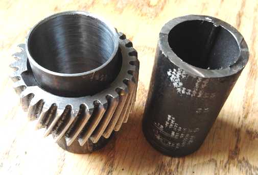
Variable
Torque Converter Transmission
Original pipe (R) and bored-out pipe with gear (L)
 Having decided
I should complete the transmission unit and
try it out regardless of new AFSRM and fixed ratio belt drive designs, I started machining of a shaft adapter to
make the 1.0" Electric Hubcap shaft fit the 1.064" transmission
planetary sun gear on the 14th, by boring out a piece of pipe that
seemed to be right on 1.064" O.D, to 1.0" I.D. It was slow work and I
only got
1/2 way. I got back to it on the 18th. I decided it should fit the
shaft as a "pressed fit", and left it a few thou under 1.0". It
wouldn't go on readily when hammered, even heated with a torch, and I
didn't finish. Perhaps a couple more thou would have been good to take
off. The end pounded on expanded a little, which might make for a good
press fit to the gear as well... but only if I could get it on at all,
and if the gear didn't break in the process.
Having decided
I should complete the transmission unit and
try it out regardless of new AFSRM and fixed ratio belt drive designs, I started machining of a shaft adapter to
make the 1.0" Electric Hubcap shaft fit the 1.064" transmission
planetary sun gear on the 14th, by boring out a piece of pipe that
seemed to be right on 1.064" O.D, to 1.0" I.D. It was slow work and I
only got
1/2 way. I got back to it on the 18th. I decided it should fit the
shaft as a "pressed fit", and left it a few thou under 1.0". It
wouldn't go on readily when hammered, even heated with a torch, and I
didn't finish. Perhaps a couple more thou would have been good to take
off. The end pounded on expanded a little, which might make for a good
press fit to the gear as well... but only if I could get it on at all,
and if the gear didn't break in the process.
The next morning I thought
if I lowered the bottom of the hydraulic press I could fit the whole
motor into it. Since the motor shaft stuck out both ends (I left
extra!), all pressure would be on the shaft. I cut the munched hammered
end off and squared it off. After a couple of trials with a short piece
of shaft, I put in the motor with the adapter and the gear on the end.
With 3 tons of force, it started to go together. I took it bit by bit.
For the last bit it was up to 9 tons, and the gear was on, all but
flush with the end of the motor shaft. The gear hadn't split open and
the motor shaft hadn't bent. With maybe .05" left to go, there was some
munched adapter metal in the way of getting it 100% flush. I quit there
while I was ahead.
So there's no key in the shaft, but I don't think there's
any chance of the gear slipping. It's on as solid as a rock. One hurdle
overcome!
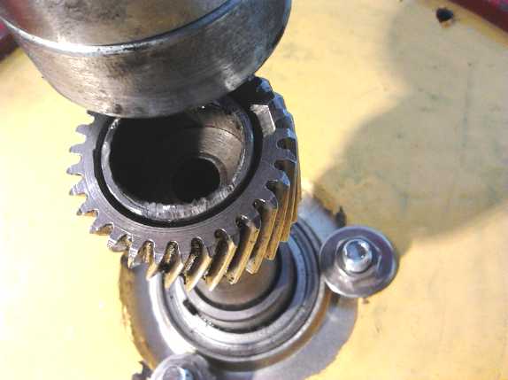
 Pressing the gear on. I quit while I was ahead
at 9 tons pressure with the adapter end squashed down.
Pressing the gear on. I quit while I was ahead
at 9 tons pressure with the adapter end squashed down.
Let's see... that leaves installing the unit in the Sprint
and devising a new linkage for the slipping gear to the shift stick,
then installing and wiring up the Kelly 300 amp BLDC motor controller,
then fitting in some batteries of some description for testing. Then
testing the motor and controller, then the transmission. I'm probably
missing something, but that's the list for now!
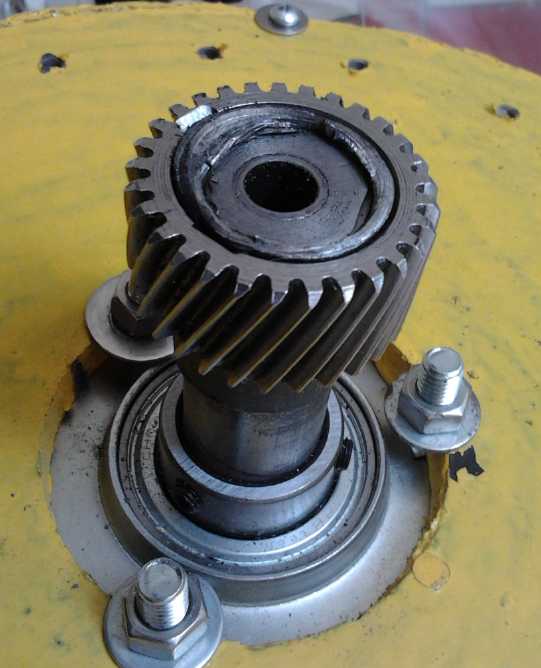
 Variable Transmission Assembly:
Electric hubcap motor, Variable planetary gear torque converter assembly
with large pulley on the slip element, large, low RPM centrifugal
clutch,
chain sprocket & chain drive to car differential at bottom.
Electric
Weel Motor (Generator)
On the 8th Rick Linden came over and we started assembling
the
unit. We made some progress, but hit a snag. While I had
made it sufficiently tall (or 'thick' - or 'long' as motors are usually
measured) to
accommodate the thickness of the rotor with the magnets around the rim,
it needed considerably more room in the middle for the bearing
assembly. The bearing for a 1.75" shaft is after all almost an inch
thick. That might have been mounted on top, but it needed even more
headroom in the center because the plastic rotor assumed a slightly
"cupped"
form, since the magnets all around the outside were attracted to the
stator and it wasn't as solid as metal.
We thought of spacers and mounting the top above the body
of the outer/center rim. The more I thought about this the less I liked
it. I decided to add an inch to the height by epoxying on 1" PP
strapping. But I didn't have any 1", and decided to go with 1.5".
Contrary to my original idea to make it no thicker than necessary, I
decided that extra
space is better than insufficient!
On the 9th I epoxied on a ring of 3" nylon(?) strapping
around the outside to form a solid wall to glue the 1.5" against. Three
more sessions, days apart, were required and I finished the job on the
18th, but when it was done it looked like it had been made that way in
the first place.
 Epoxying on more layers of polypropylene
strapping/webbing to extend the height.
Epoxying on more layers of polypropylene
strapping/webbing to extend the height.
Finished height extension, wiring it up, with
diode rectifiers.
I had bought a new weigh scale, because the old one, which
had to have the button held down several tedious seconds to turn it off
manually, had a penchant for turning itself off automatically even
while pouring in epoxy. With the new one, I started dribbling
in the last of the hardener from an almost empty can... and as it went
in, the scale read 0... 0... 0... 0! The scale had decided for itself
that the action was too slow, and that it would keep zeroing itself
unbidden until the pace picked up, which of course it didn't! I took
off the container and it now said minus 30 something grams instead of
the minus 20 something it had been zeroed at. I only wanted 15 grams of
hardener and I had to make a rough estimate of how much I had. When I
added the resin, I dumped in a bunch at once to ensure it wouldn't
simply zero itself again, and in doing so, I had already added too
much. I had to add more hardener and so mixed more epoxy than I wanted,
which surplus amount went to waste. Another
worthless weigh scale! Where do the people who program microcontrollers
in appliances come from?
As there was now sufficient room inside and the rotor was
still more flexible than desired, on the 24th I cut a larger
reinforcement disc piece with the CNC router to glue to the other side
to stiffen it. Later that day Rick and I solved ('glued') it on with
methylene chloride.
We decided to wire all 8 coils of each phase in series,
with marettes connecting the two 4 coils per phase sections, and to put
diodes directly inside the unit to rectify the 3 phase AC into DC. Then
just have two wires coming out, "+" and"-". If the voltage is too high,
we can change it to two parallel sets of 4 coils per phase, but usually
the voltage from a generator is lower than you'd expect. In fact, it
seemed to be only 2.25 volts at 60 RPM. Apparently coils with more
turns of finer wire would have been better. But it should be workable.
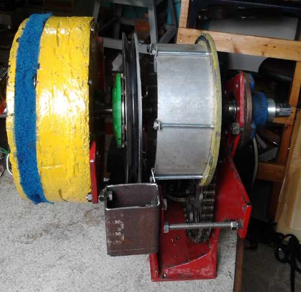
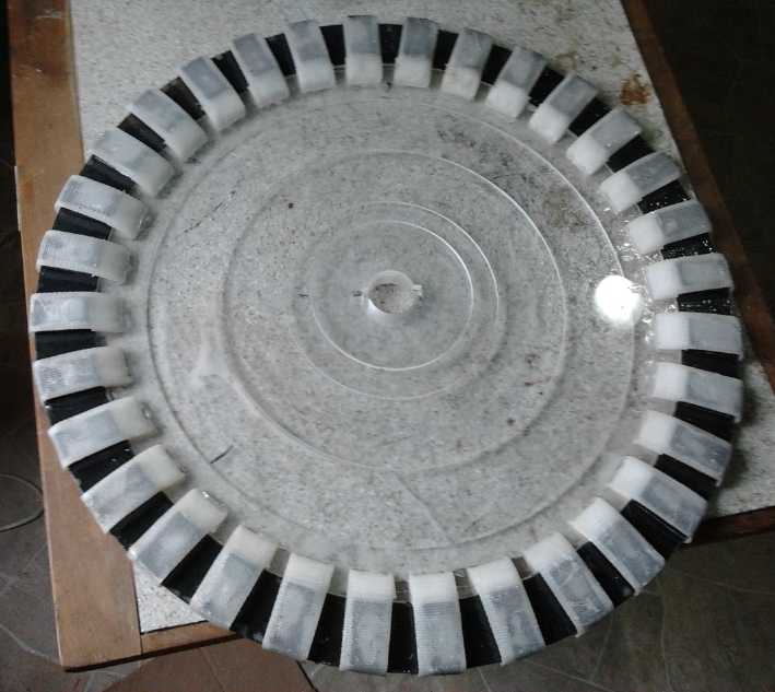 Completed magnet rotor with 4 reinforcement
pieces to reduce flex and "cupping".
Completed magnet rotor with 4 reinforcement
pieces to reduce flex and "cupping".
"Green" Electric Equipment Projects
Aquaponics
& LED Grow Lighting Project
Has Beans
A few of the bean leaves here and there started to wilt.
On the 11th I got out the scissors, snipped the vines to more
manageable lengths, and pulled the beans out from the grow bed. They
had bean there for 6 months, longer than they grow in the garden, and
still there had been just one short lived flower and no beans had been
had. There were some thick stems at the bottom, connected to thick
masses of roots. The supports for the LED lights had to be extracted
from the vines later, outdoors. In some areas the roots didn't have to
be dug out of the lava rock. Rather, the lava rocks had to be shaken or
pried from the clumps of roots. Even this wasn't feasible in some areas
and I threw out the lava rocks with the roots. Perhaps I'll recover
them later.
A friend had visited a commercial aquaponics op in Powell
River, and he reported to me that same day. (11th) He was told that for
a small setup like mine, the drain-down bed was indeed the way to go.
The rocks were more effective with the strong currents periodically
flowing past. And the lumpy, porous lava rock was by far the best
material, with ten times the surface area of smooth rocks.
But beans? He was told: "You won't get anything. Grow
leafy
greens." Well, I guess the nutrient mix just isn't right for legumes.
But I got two things out of three right! In fact, much of what I
planted was leafy greens, but the beans grew so prolifically they
shaded out and killed everything else. This time, no beans or peas!
I'll go for just spinach, lettuce and (an aquaponics bed favorite if
not a culinary one) basil. But I have seen tomatoes and peppers in
various aquaponics videos, so those aren't to be ruled out.
More Tilapia?
On the 17th I noticed the big female tilapia wasn't
eating, or at least not much, and looked more closely. It appeared she
had eggs in her mouth. This surprised me. The 3 tilapia in the aquarium
are so aggressive I had to separate them with wire mesh into 3
compartments. But later she ate. Rats!
Electricity Storage
Turquoise Battery
Making Project
Cylindrical Batteries?
Metallic Nickel Negodes from Cupro-Nickel Sheets & Micro-fine
Nickel Powder
Edison apparently used hot sulfuric acid to dissolve
away layers of thin copper sheets from thin nickel sheets (each
.001", I think) in connection with making his nickel-iron
batteries. It was said that the solution did have nickel sulfate in it
- whether originally or as a result of reaction it didn't say
explicitly, but it seems the spent solution was processed to recover
the copper and nickel, so it was probably dissolving the nickel to some
extent too.
 Initially I
tried hydrochloric acid with hydrogen peroxide
on a piece of nickel-brass. But that dissolves nickel, perhaps faster
than copper. The piece ended up with a dull greenish appearance.
Initially I
tried hydrochloric acid with hydrogen peroxide
on a piece of nickel-brass. But that dissolves nickel, perhaps faster
than copper. The piece ended up with a dull greenish appearance.
I
decided to use ferric chloride instead. We know it dissolves
copper. It was highly
likely it would do zinc, but it's
only a "mild" oxidant and it might leave nickel alone. My first idea
was to simply assume this would be the case.
Experiment: But why trust to
luck? I have pure zinc! I stuck a
small piece of about .006" (34 gauge?) zinc in some ferric
chloride etching solution to make sure it vanished. While I was at it,
I stuck in a very thin flake of (?) .001 to .002" thick nickel too - a
bit of nickel electroplating off a supermagnet or something. (In this
measurement we hit the resolution limits of the digital caliper
micrometer.) I expected the zinc to dissolve and the nickel to be inert
(and who cared how long it took?), so I didn't properly note the times.
All trials were at room
temperature.
Observations:
- The zinc dissolved in around 15 or 20 minutes.
- The very thin nickel flake dissolved, but it took over an hour. And
the piece was rather curled up, so one side didn't sit flat on the
bottom: it was dissolved from both sides, while the zinc would have
been mainly from one side.
- We already know copper will dissolve, but how fast compared to the
other two? I took a tiny piece and hammered it to about .006" thick,
similar to the zinc. It wasn't gone in an hour, but it lost .001 or
.002" thickness. I wasn't sure how clean the surface was to start with,
and I had used only a little solution, so I did another copper piece,
scraped it with a knife, and put it in more of the original solution in
case the first one was weakening. Of course the copper pieces sat on
the bottom, so mainly only the top was exposed. After around 3 hours
for the first piece and 2 for the second, there wasn't much left.
Conclusions: It was hard to decide just how thick the nickel
flake was - between .001" and .002" is double or half. And, I didn't
record the starting times for each piece. (I look at the clock, and
think I'll remember the time, but often I don't.) So all this is
somewhat approximate. But the general impression is that zinc dissolves
fairly quickly, while the nickel and copper take an order of magnitude
longer, and both of them seem to dissolve at more relatively similar
rates. Given the conditions, the copper probably reacts somewhat
faster, but it depends on what one decides was the original thickness
of the nickel flake, and which copper piece is most relevant.
Taking the second piece of copper as two hours to dissolve
(mainly from one side since it lay flat on the bottom) and .006" thick,
with the nickel as .0015" and one hour to dissolve (more from both
sides since it was curled - but first it was floating from surface
tension for maybe 10 or 15 minutes), the copper would be perhaps around
three or four times faster reacting than the nickel. (Say, that's
better
than I initially thought!) The hope that the nickel would be left
behind without reacting was proven false, but since it seems to be
slowest reacting, it looks like the process could make a good
electrode. It might even be "optimum".
Next Experiment:
I left a small
piece of nickel-brass in ferric chloride
for an hour. It was splotchy: some areas had a nickel (I presume)
shine, while others were somewhat more yellowish like brass. Under 40x
magnification there were rough ridges running one direction, suggesting
that the metal alloy elements had separated somewhat during rolling.
Presumably the zinc-rich "lanes" would have dissolved leaving these
more copper and nickel rich ridges. The differences between the
(presumably) brighter, silvery nickel shine and the more yellow tinted
areas were one of degree. Both had lots of bright nickel bits at the
surface, tho yellowy copper was more predominant.
These are my interpretations of what I was looking at.
Since zinc also has a bright shine, it's theoretically possible the
exposed bright clusters were zinc rather than nickel. That would be
contrary to expectations, but without electron microscopy or some other
test, who knows? If there was no zinc in the alloy it would eliminate
the chance that remaining zinc would cause anything unexpected.
One thing to try was to agitate the solution with
the nickel-brass in it, and see if it still has those splotchy areas.
They could be the result of non-uniform exposure, perhaps with
dissolved metal blocking the solution and slowing further action in
some places. This produced lines in line with the waves made by
agitation.
I might try sulfuric acid
some time, but I really don't
expect better results than with ferric
chloride.
Perhaps a different alloy would be more ideal? One could
leave the suspect zinc out, and just use something with more copper to
dissolve out for more micro-porosity and more nickel - maybe Cu:Ni
60%:40%. Or, might one try some other 'sacrificial' metal besides zinc
to dissolve out to maximize surface convolutions? Manganese? Aluminum?
a heavy metal?
There's probably an ideal alloy somewhere. But unless I'm
going to take up metallurgy I'm probably stuck
with what's freely available on the market.
A search for monel (Ni:Cu 65:35%) revealed that metal
companies seem to have improved their web presence since 2008-2009 when
I looked before. Monel turned out to be overly expensive, but
eventually I found cupro-nickel alloy (Cu:Ni 70:30%) - not far from the
60:40 idea above.
The other variable is the concentration of ferric
chloride and length of time it's left in the solution - and maybe
whether ferric chloride is optimum anyway. Much copper and a little
nickel should etch away to make a rough, convoluted surface, exposing
far more nickel atoms for
reaction than any smooth sheet of metal. Maybe an hour or so of etching
would make
for good results.
A quite different idea would be to try 'brass' but with
more zinc and less copper, like 50:50, or 60:40 Zn-Cu, or whatever.
Dissolve out the zinc (HCl acid without H2O2 will dissolve zinc but not
copper) and then electroplate the porous copper with nickel. But
electroplating would probably build up a much smoother, less porous
nickel surface than etching away. It would then have lower amp-hours
per amount of nickel.
Next, what about bonding the monel powder onto the surface
of the nickel-brass (or monel) sheets? My best thought was to sinter
them together, so that the pieces actually fuse metallicly, but just
where points touch, not to the extent that the powder particles melt
and
flow together so it becomes a solid, smooth sheet. I've sort of tried
to do
this before, but I started thinking that a flux is required, and
that some things would doubtless work much better than others. The flux
keeps air
away to prevent surface oxides that won't melt from forming, and in
this job it needs to hold the monel powder on the sheet so the flame
doesn't blow it away before it can bond. Borax is a commonly
used flux, but I don't think it'll do the holding part, and it might be
hard to remove. Salt will also blow away. I decided to try gum
arabic from the art store. Apparently it's used in pyrotechnics as
well as in food and ordinary things, so it must withstand a high
temperature for a bit. And it'd be water soluble to rinse off
afterward. (I think.) For heat, a high heat for a brief period with
little oxygen is ideal - just melt the particles a little bit to fuse
them into a porous solid. This heat can be had from a propane torch,
passed fairly quickly over the work. (A few seconds total.)
My first
thought was
that bonding the monel powder onto the sheet
(into a single porous surface with "large" pores) should be done first,
then the dissolving out for microporosity throughout. Fractal design!
On the 6th I found "Senefelder's Gum Arabic Solution
14°
baume" at an art supply store to use for a flux. I took my first little
ferric chloride etched nickel-brass test sheet and painted some on,
then I sprinkled on some monel powder. It seemed quite thick, but it
was only .85mm total thickness. That's typical of a NiCd dry cell
electrode, but I'm not doing rolled up electrodes and it should be
twice that thick.
The next morning I torched it for a few seconds. Then I
looked at it through the 40x magnifying glass. It didn't look so much
like the "fractal broccoli", but it was the same sort of idea. Shiny
nickel/monel lumps on top of other lumps on top of others, with gaps in
between where electrolyte would flow in and wet it all. In one place
there seemed to be a bit of left over gum. I tried to rub the surface,
and then to scrape some off with my thumbnail. I could feel a bit on my
fingers on both tries, but most of it seemed pretty well adhered -
doubtless better than anything I've done before. The thickness wasn't
uniform enough that I could tell if it had shrunk any with the
torching. It didn't seem like it. I meant to check the electrical
resistance at this point, but forgot.
Then I put the piece in ferric chloride for 20 minutes
(again, at room temperature) to see how that would "fractalize" the
surfaces of the tiny monel powder lumps. (An hour might dissolve them
completely, or at least remove too much material.) That seemed to wreck
things. Half the monel was gone, leaving the sheet underneath. Despite
the torching, it seemed it was still the gum holding it down, and the
ferric chloride had dissolved some of the gum.
However, the appearance of the rest when magnified
reminded me of a forest canopy. "Trees" filled all the spaces Many of
the monel chunks didn't seem to have smooth surfaces any more.
I tried torching part of it again, this time leaving the
torch on until parts of it turned blue. I got slag and apparently no
better bond. But perhaps the gum arabic could be the binder to hold the
powder on, and it would be permeable to the electrolyte. It could be
like the agar I tried to gel electrodes with quite a while back, or
like the CMC gum used to 'glue' some electrodes together. (tho I think
more on positive electrodes than negatives.) Electrical
resistance from any point to any other was mostly under an ohm if not a
dead short, usually with little pressure applied to the meter probes.
(A couple of pounds? To break through any
slag?) That seemed amazing for an electrode that hadn't even been
compacted.
As I noted in some TE News long ago, the untreated monel
powder didn't seem to have anything like as much surface area per
volume as one might hope. Yet etching such tiny grains would have to be
done very carefully. A little too long in the etchant and there was
likely to be not much left. And it would take time to dry and be usable.
On the 7th I looked up fine nickel powder at
micronmetals.com, and discovered that available "nickel flake" powders
have much finer particles than the monel. Regardless of etching away
copper from monel, it would seem that ultra-fine flakes, 1 to 5
microns in size, should have far more surface area per weight. So
I ordered some.
I went to order monel sheet as well, but it was too
costly. I ordered cupro-nickel 70:30% sheet instead from NEAlloys.com.
Here the zinc is gone
and the sheets will have convolutions with more nickel on the surface,
and the
nickel powder probably won't need etching to be excellent. (Not that I
won't probably try it and see if it helps.)
On the 21st the nickel powder arrived. I compared it to
the monel powder at maybe 8x magnification. It didn't seem much
different. Then I tried 40x. At this scale I could see that the nickel
"particles" were actually "fluffy" clumps of much finer very thin
flakes, while the monel particles were fairly smooth skinned blobs or
"potatos". The nickel micro-flakes obviously had far more surface area
than the monel, by weight or by volume. The monel would spread out,
while the nickel particles clumped together and didn't want to separate.
It then occurred to me that another way to 'sinter' metal
particles together is with pressure instead of heat. But was that
necessary? An ohm meter showed that the powder (nickel flake or monel)
in gum arabic on an etched nickel-brass sheet was an extremely
conductive electrode with no more pressure than would press the
electrode flat inside the cell anyway.
Tentatively it would seem that the procedure should be (1)
etch the nickel-brass monel cupro-nickel sheet
and the powder first,
(2) apply the gum arabic and (3) sprinkle the etched monel
powder fine nickel flake
into the gum until it's saturated. Probably repeat (2) and (3) to get a
thicker electrode.
(4) Compact the electrode in the press... if it seems to improve it.
I'm not so sure about pressing it. Unless the amount of gum is limited
so it oozes through the powder as it's compacted. Otherwise it'll just
be oozing out everywhere, or be non-compactable. It would appear just
the pressure inside the battery should be enough to produce pretty much
a short circuit between all points in the electrode, with the metals
all being so conductive.
But during discharge, exposed nickel turns into nickel
hydroxide, so it's best that the flakes are connected by some bridge or
other of copper or unexposed nickel, which might make some amount of
compression valuable.
Dry Cell Assembly Is Made Easier!
I've had the thought that rolling up sheets of
cupro-nickel into
tubes with an open seam (instead of making making a cupro-nickel "can"
or a
tube with a sealed seam) is actually a big advantage for assembly
because the seam can be spread apart during assembly.
The compacted powder central 'positrode' can be wrapped
with separator paper and the carbon rod inserted. Then the slightly
open outer 'negatrode' sheet (of cupro-nickel with nickel flake glued
to the
inside face) can be slipped up around it with no friction, ensuring
that in that operation no nickel flake is rubbed off, the separator
paper isn't ripped, the pressed 'positrode' doesn't crumble, and the
carbon rod isn't cracked. Then as it's being inserted into the PVC pipe
the outer sheet tightens around the inner part, but it's all inserted
as a single unit. Nothing is sliding against anything else except the
solid metal sheet against the PVC pipe.
This greatly increases my level of confidence in the
practicality of the cylinder layout. And if I find means to make carbon
rods myself, I could see making cylinders as long as 5 or 6" or so,
which might (hopefully) be 30 or 40 amp-hours. It seems small for EV or
off grid
use, but big batteries are built up from small cells or small
plates.
Posode Compactor/Press
Before the middle of the month I got together 6" long
pipes and a spike of the right diameters to create the press for the
central nickel manganate 'posodes'. The outer pipe was steel, about
19mm I.D., which will be the O.D. of the electrode. A pipe was found to
fit inside. I was told it was was "cupro-nickel", copper with some
nickel. It had unusual color, from silver-orange copper to
silver-yellow brass to silver-white nickel, depending on the light. The
pipe had to be
filed off to slide in easily, partly because even over 6" it wasn't
quite straight.
This pipe material gave me the idea to look up and then
look for 70:30 cupro-nickel sheet, instead of monel sheet. I ordered
some on the 17th. It's cheaper and probably will end up after etching
with a mainly nickel surface with more convolutions than monel.
The inside diameter of that pipe was still .5", much
fatter than the carbon rod. I got a piece of small stainless steel pipe
for that, .5" O.D. and just over 11/32" I.D., a perfect fit for inside
the cupro-nickel and an 11/32" diameter, 8" long spike to make a hole
for the carbon rod. I machined the spike so the head fit just inside
the outer pipe.
So the electrode making procedure is to mix the
ingredients, pour them into the outer pipe with spike sticking up, with
a funnel, then push in the inner pipes and press them down with the
hydraulic press until the powder has become a solid cylinder. Push it
out, remove the spike, and insert the carbon rod.
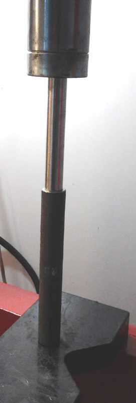
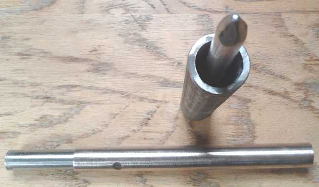
The Posode Compactor
- spike for center hole for 8mm carbon rod
- outer body pipe, 17mm I.D. (O.D. of electrode)
- 2 telescoping pipes together 17mm O.D., 8mm
I.D.,
to cram down the powder into a porous 'solid'
with the hydraulic press..
Aluminum Ion DES Battery - "Moving
Target" battery chemistries?
Egads, stop the presses! Leonardo Elionix, whose
manganese-air battery I mentioned in TE News #85, offered to send me
some deep eutectic solvent (DES), "ethyline", that he had made from 2:1
molar ethylene glycol and choline chloride (antifreeze and vitamin B4).
It freezes at -10°C and starts decomposing at 330°C.
Again, "DES" is an inert compound of two or more salts
combined
at an ideal ratio, that is liquid at room temperature. People have made
effective batteries with liquid salt electrolyte in place of water
solution based, but they have to run at oven temperatures or higher to
melt the salt. The idea of combining salts to get one with a below room
temperature melting point seems to be pretty new, at least as applied
to batteries.
Then on the 11th I looked at an article a friend sent me a
link to, on an aluminum ion battery using a polar DES electrolyte. It
has never been possible to make a rechargeable or even stable battery
with aluminum using water based electrolyte, because the high reaction
voltage of aluminum causes the water to electrolyze and discharge the
metal, making hydrogen gas plus aluminum hydroxide or some dissolved
aluminum compound, without connecting an external circuit. The DES
employed as an electrolyte evidently has a higher reaction or breakdown
voltage than
aluminum, and so it and the aluminum are inert until an external
circuit is connected.
The new chemistry seems to have various advantages over
lithium ion, including that it's safer (can't explode), cheap, fast to
charge and discharge, and it seems to have "forever" cycle life (as I
believe I've also found in NiMn and NiNi) having been cycled 7500 times
with no apparent loss of capacity. It's certainly simple: In
discharging, aluminum in the negode releases an electron, becomes a
chloride ion and migrates to the graphite posode, where it absorbs an
electron to become an aluminum chloride compound. In charging the
opposite effect deposits the aluminum back onto the sheet, seemingly
pretty much as it was, with no formation of dendrites ("tentacles",
"strands") as occurs with
zinc.
The NiNi [dry?] cell construction I worked out only last
month (March) and it should work great if I can assemble it so it
doesn't fall
apart, short out or leak significantly - as it is specifically designed
to accomplish. And I'd just figured out in the last couple of weeks
how to make a fabulous nickel 'negode'. The gum arabic seems like it'll
gel the nickel flake to the metal and make it work really well. I'd
just ordered fine (and pricey) nickel flake, and I was in
conversation with a manufacturer to order monel sheet metal. The the
previous day
I had obtained and cut pieces of metal pipe to make a positive
electrode
compactor for the cells. After months of not knowing what to do next,
it was virtually all set to go.
Now I hear of a brand new chemistry that sounds better,
cheaper, simpler, practical to make, and has some good research behind
it: the aluminum ion DES cell. Except for obtaining the electrolyte, it
sounds even easier to make. Perhaps the ethyline would work?
(Admittedly wishful thinking.) Or perhaps I can buy the same stuff the
researchers at Harvard used, somewhere. Hmm... my dad got his PhD from
Harvard... around 1951... can that possibly be of any use?
So now what? It looks very much worth trying out. If
'production' cells works like the prototype test results show, most
other battery chemistries just might be dead in the DES. Would I then
be wasting my time doing the NiNi?
Or perhaps I'm drawing hasty conclusions... DES.es could
enable many new types of cell chemistries, particularly if the
ultra-low evaporation rate Leonardo claims were to make air (oxygen)
electrodes practical. The Elionix manganese-air cell sounded great.
Where I spent a lot of time and trials finding trace additives to get
manganese to hold its "a little too high" negative voltage charge in
salty water solution, his ethyline electrolyte probably has a higher
breakdown voltage than water, so manganese simply works in it without
issues. And what about nickel-air, or maybe even aluminum-air, with
ethyline? A long lasting rechargeable cell with an air electrode is
almost a "holy grail" for battery making. It removes most of the weight
and bulk of what is usually the less energy dense electrode, making
much higher energy densities possible. The fact that water in contact
with air evaporates, yet the air electrode can't be flooded or
contained, makes it
hard to maintain the requisite humidity over any length of time. A DES
with a very low evaporation rate might change the picture.
I smugly thought I had two battery chemistries that were
better and safer than anything out there, but was having trouble making
practical
batteries of any sort. And now, just when I thought I had everything
all figured out, DES.es may bring out new, seemingly superior battery
chemistries with a variety of new possibilities, all suddenly "dumped
in my lap" for consideration. All very exciting, but I really hate
moving targets!
But perhaps I can use the new cell construction I've just
devised, and just change what goes into it. ...Or would flat again be
better for a cell with an air electrode? I think I'll just go with the
Ni-Ni chemistry I've devised for now, and try it with the ethyline DES
electrolyte as well as with salt solution. Theoretically I could have
started this immediately using the monel powder and the nickel-brass,
but I decided to wait for the nickel micro flake/powder and
cupro-nickel 70:30 sheet, which I finally got ordered by the 17th.
The cupro-nickel sheet arrived on the 29th, so I expect
I'll put together a cell next month. Unlike the sample piece of pipe,
it was very silvery without much or any trace of orange copper color.
I'm guessing that the pipe was 90:10 Cu:Ni alloy while the sheet metal
is 70:30, and that the 30% bright nickel 'overrides' the copper's
color, just as the nickel-brass is silvery color even with 65% copper.
The ethyline hadn't arrived by May 3rd. I suspect that the
post office, not knowing what it is, will refuse to deliver it, or
customs will refuse to let me have it. I can't even find ethyline on
the web, except that it seems to be the French spelling of ethylene,
the name of a rock band, and a subcomponent of some organic
compounds with very long names. Leonardo's instructions were a little
sketchy for me, but I'll check out chemistry supplies for the
ingredients and write to him if I can't figure out how to make it.
http://www.TurquoiseEnergy.com
Victoria BC Canada