Turquoise
Energy Ltd. News #88
covering May 2015 (posted June 3rd)
Victoria BC
by Craig Carmichael
www.TurquoiseEnergy.com
= www.ElectricCaik.com
= www.ElectricHubcap.com
= www.ElectricWeel.com
Highlights:
* New configuration Bipolar BLDC Motor to use improved reliability
Unipolar Motor Controller (Month in Brief)
* Electric Weel: 'finished' at last, but... (Month in Brief,
Electric Hubcap Motor Systems)
* Geo-engineering: Playing Russian Roulette with Earth's Environment
(In Passing)
Month In Brief
(Project Summaries)
- NiNi cylindrical batteries - Electric Weel Hydro Generator -
Using a Unipolar Motor Controller for Bipolar BLDC motors! - Electric
Ooutboard from Scratch Revival? (with Caik motor & unipolar
controller, and double U-joint at foot) - Making a Flat Drive
Belt - Various NiMH Batteries & RX7 EV - Aquaponics... wheat field
- Thermoelectric: fridge update, heat pumping - Solar Hot Water? -
Paperwork for CRA -
Commercialization?.
In Passing
(Miscellaneous topics, editorial comments & opinionated rants)
- Borax for Arthritis? - Geo-Engineering... potential human extinction:
Chem Trails!...
HAARP Too!... Unnatural Disasters? - The Three Core Values of
Social Sustainability.
- In Depth Project Reports -
Electric Transport - Electric
Hubcap Motor Systems
* Giant Electric Weel Generator
* Making Flat Drive Belts from Polypropylene (or other)
Webbing/Strapping
(Flat belts are 99% efficient!)
Other "Green"
Electric Equipment Projects
* Aquaponics & LED Plant Lighting update
* Thermoelectric (Peltier Module) Fridge & Space Heating Update
Electricity Generation
(no reports)
Electricity Storage - Turquoise Battery
Project (NiMn, NiNi), etc.
* The Battery Construction Puzzle
* Sheet metal Roll-bender; rolling up a negode sheet
* Making up NiMH "sub-C" power tool batteries, Electric Mazda RX7 NiMH
"D" cell pipe batteries
No Project Reports on: AFSRM,
Variable torque converter transmission, Magnet
motor,
Lambda ray collector, evacuated tube heat radiators, CNC
gardening/farming machine.
May in Brief
It appears I'm finding more time to come up with exciting
ideas,
and then to write about them while they're in mind, than I am to get
new development done. There are a bunch of topics here, each more than
a paragraph but
mostly too short to move to "detailed reports" and then to mention them
anyway
in a shorter form in "May in Brief", so the e-mail is rather long. The
main physical
accomplishment was (at last!) the complete assembly of the Electric
Weel
motor/generator.
Time, time, where is the time to get all these things
done? Months and then years are stretching toward a decade. Projects
and concepts have advanced to the point where I could certainly
delegate much of the work if I had help, and then things could proceed
pretty rapidly. I simply have to come up with means to get a few other
people
involved in some of the projects and developments.
I also wrote quite a piece on geo-engineering in "In
Passing". To all appearances, it has altered climate and grossly
increased and accelerated global warming, a most serious development.
There must be quite a few people who've taken leave of their senses for
this to be secretly going on. The climate disasters that appear to be
artificially caused may directly cause massive loss of human life. Why
is India now hotter than the Sahara desert?, and what happens if any
major portion of the 38 million people in California get nothing when
they turn on their faucets in about a year? As sea levels rapidly rise
in upcoming decades, what happens to the 160 million people of
Bangladesh, much of which is hardly above sea level now - not to
mention countless coastal areas?
Nickel-Nickel Cylindrical Battery
I had expected to get right onto the battery making
project and get one made, but time went elsewhere. I etched a couple of
pieces of
cupro-nickel. Under the 40x magnifying glass, the surface roughness
looked convoluted - very fractal. That was the desired result - lots of
nickel surface area to react.
I made a "mini" sheet metal roller for the 'negodes' on
the 28th. It looked nice. I wasn't very happy with the result and I'll
doubtless change the roller setup, but I rolled up an electrode that I
decided was "good enough". That was as far as I got.
Giant Electric Weel Generator for Floating Hydro Power
 The overriding
project of first half of the month was
assembling the Electric Weel generator, and partly mounting it in the
transmission assembly for the floating hydro power unit. But once it
was together, the electromagnetic coupling - the volts and potential
amps and watts at a given RPM - was beneath minimum expectations.
The best that could be coaxed out of it by careful adjustment at 60 RPM
(we could get this speed turning it by hand) was about 5 volts open
circuit and maybe 6 or 7 amps short circuit. (I couldn't get it up past
about 30 RPM shorted.) A "maximum power point" for 60 RPM might be
between 4V * 5A = 20 watts and 5V * 6A = 30W. At a top speed of 600
RPM, that would come out to maybe 2000-3000 watts.
The overriding
project of first half of the month was
assembling the Electric Weel generator, and partly mounting it in the
transmission assembly for the floating hydro power unit. But once it
was together, the electromagnetic coupling - the volts and potential
amps and watts at a given RPM - was beneath minimum expectations.
The best that could be coaxed out of it by careful adjustment at 60 RPM
(we could get this speed turning it by hand) was about 5 volts open
circuit and maybe 6 or 7 amps short circuit. (I couldn't get it up past
about 30 RPM shorted.) A "maximum power point" for 60 RPM might be
between 4V * 5A = 20 watts and 5V * 6A = 30W. At a top speed of 600
RPM, that would come out to maybe 2000-3000 watts.
This was disappointing from something so large and capable
of handling far more power. Apparently my design is a better motor
than a "passive" generator.
There is still one way to pull a rabbit out of the hat.
With a motor controller connected, it could be set into what's
described as "regenerative braking" mode, which can increase the output
a lot. And as an "active" generator, the output can be matched to the
force available - torque and speed - and to the load. It's
"programmable".
Until now, this would have meant ripping half the magnets
off the rotor and flipping them over, since the "generator max" magnet
pole configuration of NSNSNSNS.... would need to be replaced by the
standard NNSSNNSS.... motor configuration. (2 rotor magnet poles per 3
phase coils instead
of 4 per 3.) But read on!
New Concept: "Unipolar" Motor
Controller for Bipolar BLDC Motors!
An exciting new possibility drifted into my consciousness
toward the end of the month. As I found in 2008 when I first started
making motors, if there are four rotor magnet poles for each three
stator coils, as there are with the Electric Weel generator as made,
the magnetic forces cancel out and the motor won't rotate. Thus... with
the standard type of BLDC motor controller... this magnet configuration
can only be used as a passive generator.
But if I use the new unipolar/SR motor controller, only
one phase is on at
a time instead of two, so the thrust forces don't cancel and the
present magnet configuration could be made to work.
Traditionally for a 3-phase BLDC motor there are two rotor
magnet poles for each three stator coils. One phase is driven "north"
while another is driven "south", with two phases active at any given
time, all switching around as the rotor turns. To send the power to the
coils, the controller employs a 3-leg H-bridge of power transistors.
As mentioned before, the H-bridge has inherent reliability
issues owing to the fact that most any "glitch" or failure can cause
the
transistors to short circuit right from the power to ground, a
catastrophic failure mode which usually destroys multiple electronic
components, ruining the controller.
It would be desirable to eliminate the H-bridge as in the
unipolar or SRM motor controller. And the 4 magnet poles per 3 coils
configuration is actually better than 2. Finally I thought of these two
things together
instead of separately. They make a matched configuration that
will work. With the unipolar controller, only one phase is active at a
time, so the balancing of magnetic forces resulting when two phases are
active
doesn't happen. There can be forward (or reverse) thrust in all
positions of
rotation. And in spite of only one phase being on at a time instead of
two, it's probably no weaker because the ON coil is always both pushing
on one magnet and pulling on another, working in the strongest magnetic
flux where the poles transition, and there are twice as many
transitions per rotation of the motor.
Therein appears to be potential for making superior, more
reliable BLDC
permanent magnet motors, using the same motor controller that can run
an axial flux switched reluctance motor (AFSRM). They
will have lower torque ripple than the 3-phase AFSRM because the coils
are both pulling and pushing on magnets, and during rotation, as the
push
on one magnet weakens the pull on the other strengthens. And the
simpler hall sensor magnet
position sensors can be used where the AFSRM needs optical sensors.
A third and not inconsequential advantage is I can already
make BLDC motors and (except for the control change) I know they work
really well, whereas I haven't yet built and tested an AFSRM motor, and
the exacting physical requirements of AFSRM.s with their
sub-millimetric flux gaps potentially pose
production problems. With one having smoother torque and the other
being capable of very high RPM.s, it may be that both types will prove
useful in different applications.
Electric Outboard 'from scratch' Project: almost revived? ... to be
revived?
I was apprised by Jim Harrington on the 10th that the
University of Victoria mechanical department was looking for a student
project, which would be picked on the 12th. There was very short
notice, and he had just submitted a project.
We talked about how outboard motors for boats always have
a gearing down
down by the propeller (between ~ 2.5:1 and 3:1) because gas engines are
lower torque, higher speed. So when the engine is doing 5000-6000 RPM,
the prop is only turning 2000. This is always frustrating to anyone
converting an outboard to electric because electric motors are higher
torque, lower speed - often 2000 RPM range. So the prop is only turning
650-800 RPM instead of 2000. It really needs about 1:1; no reduction at
all.
I wrote, explaining the idea for using two U-joints, each
one changing the direction by 45° to effect the direction change
from the vertical shaft down the leg to the horizontal prop with low
losses and low noise, naturally having a 1:1 ratio, so a project would
be to make a bottom end for an electric outboard with this mechanism
and all the required characteristics.
Briefly I was looking forward to the idea of having
someone else do some of the development work that I haven't had time
for. I was told the idea came in second. Oh well!
Near the end of the month, after considering this along
with the more reliable motor controller to be used with the BLDC motors
I can already make, I
thought I'd think again about actually manufacturing electric
outboards. It should be a clearly superior product, with 6 horsepower
from the Electric Caik motor or 9 from the Electric Hubcap (considered
equivalent to about 2.5 times that in gas in marine circles), high
efficiency and improved motor
reliability. And that presumably better propeller I tried to cast an
aluminum copy of. I think they should sell. I'm not going to do it all
by myself, so it will depend what
arrangements can be made. But proving the new BLDC motor and controller
system works well comes first.
Making a Flat Drive Belt
 One experiment
I did try in May was to make a sample flat drive belt from a piece of
2" polypropylene strapping. To form a loop I melted the ends together,
using an iron isolated from the plastic with two pieces of cellophane,
above and below. Cellophane [unplasticized] won't melt. (My dad and
friends long ago made ice fishing tents this way with polyethylene!)
The belt is so strong yet limp one can see why they'd be almost 99%
efficient at transferring power.
One experiment
I did try in May was to make a sample flat drive belt from a piece of
2" polypropylene strapping. To form a loop I melted the ends together,
using an iron isolated from the plastic with two pieces of cellophane,
above and below. Cellophane [unplasticized] won't melt. (My dad and
friends long ago made ice fishing tents this way with polyethylene!)
The belt is so strong yet limp one can see why they'd be almost 99%
efficient at transferring power.
Being able to simply make any desired belt from common
material should be a big advantage. (Maybe I'll try a flat belt on my
bandsaw first, replacing the V-belt!)
Pulleys for flat belts should be slightly convex profile,
with or without retaining sides. They'd be easy to make on a lathe.
(Some readers may recall I 3D printed a couple of 7" flat belt pulleys
from ABS a couple of years ago.)
Various NiMH batteries, Electric
Mazda RX7 et al (short version - more detailed version is under
"Electricity Storage")
 I have been
using NiMH AA batteries to replace dead NiCd
batteries in cordless drills. After all this time, I checked at
all-battery.com, and found the "weird" power tool size is a standard
called "Sub-C" (for underwater use?). I ordered 52. They arrived on the
26th. I spent a couple of hours, first wrapping up a set of 15 with
masking tape because they just had cheap easily melted plastic
insulation (hazardous in a battery pack!) and
then soldering them for one 18 volt drill. It worked great! According
to Tenergy the 30 amp, 3.0 amp-hour cells should
also have 40% longer running time than NiCd. And of course far longer
life span. On the 29th I soldered together another 8 for the 9.6 volt
drill, replacing the weakening regular AA cells I originally installed
maybe 7-8 years ago.
I have been
using NiMH AA batteries to replace dead NiCd
batteries in cordless drills. After all this time, I checked at
all-battery.com, and found the "weird" power tool size is a standard
called "Sub-C" (for underwater use?). I ordered 52. They arrived on the
26th. I spent a couple of hours, first wrapping up a set of 15 with
masking tape because they just had cheap easily melted plastic
insulation (hazardous in a battery pack!) and
then soldering them for one 18 volt drill. It worked great! According
to Tenergy the 30 amp, 3.0 amp-hour cells should
also have 40% longer running time than NiCd. And of course far longer
life span. On the 29th I soldered together another 8 for the 9.6 volt
drill, replacing the weakening regular AA cells I originally installed
maybe 7-8 years ago.
What's the difference between a cheap cordless drill and
an expensive one? I think it's mainly the batteries. These "cast away"
cheap drills now perform like the best ones and should last many years.
Soldering up the 9.6V
cordless drill battery
As to the Mazda EV batteries, "D" cells, it was always the
same oldest NiMH
battery (originally 90AH) that got low first. This was one of the
"giant flashlight tube" batteries
composed of nine PVC "1.25 inch irrigation pipes" tied together. I got
the idea to
exchange 1/2 the pipes for pipes with new cells to help take the load
better. That would increase the overall driving range. And I made both
pipe batteries ten pipes for 100 amp-hours, and I changed the copper
sheets on one side to flexible wires so they wouldn't tend to pull the
end caps off. This took up the day of the 30th. Now it stays slightly
higher than [what was] the next weakest battery, but I haven't put it
to any "ultimate" range test yet. I found two actual bad cells that
won't hold their charge and may have been adversely affecting
performance - not bad out of 210 that have been running the car for 2
years and many of which were bought in 2011 and variously used
previously. And melted plastic on one of them showed it had been
overheated some time prior to putting it into the pipe.
Next, besides seeing how much farther the car goes, I'll
take some of the old cells and test their
current and storage capacity. Then I'll submerge them in water to some
particular depth (pressure) for some particular time, and test them
again. If indeed loss of moisture inside is the problem, and if a
little more
water can be successfully introduced, they should perk up and perform -
ideally like new again.
BTW: Again as the weather warms up (and it's been really warm
this spring), the car again is using less amp-hours per mile, around
10% improvement. Again the only
thing I can attribute this to is the thinning of lubricants and
whatever else would reduce rolling friction in warmer weather - or
maybe the rubber in the tires becoming more pliable? Obviously tire
friction is a considerable load.
Aquaponics & LED Lighting
Progress - Lettuce - End
of the 'Swimming' Pool - New Aquaponics Fish Tank
The lettuce here seen at
mid-month
outgrew the light on all sides by the end.
 For whatever reason, two plantings of spinach failed to
sprout. Come to think of it, the small round seeds probably washed away
with the water circulation in the loose lava rock. The leaf lettuce
started in seedling pots grew, but it seemed spindly, as if it thought
it was in the shade and was trying to
get taller to find sunlight.
For whatever reason, two plantings of spinach failed to
sprout. Come to think of it, the small round seeds probably washed away
with the water circulation in the loose lava rock. The leaf lettuce
started in seedling pots grew, but it seemed spindly, as if it thought
it was in the shade and was trying to
get taller to find sunlight.
I moved the LED grow light down from a stand couple of
feet above the bed to resting on a couple of sticks 6" above it. That
seemed to make a difference. The sunlight, now at a steep angle for the
summer, hardly came in the window, and the plants needed the LED light
perhaps even more than in the winter. Some of the leaves shot past it,
and by the end of the month it was in the midst of the lettuce insead
of above it. I move it around
a little occasionally to simulate the movement of the sun. ...And
occasionally I forget to turn it on in the morning and the plants go
with only indirect window light most of the day. Anyway the lettuce is
growing nice big leaves in its quest for light.
I have the impression that it would be best to have these
LED lights spaced fairly closely together, if not abutting, 14-18" or
so over the whole grow bed. Four would be a good start; six or even 8
would be better. That's around 60, 90 or 120 watts. It seems like a
lot, but growing vegetables isn't even possible under a 100 watt
incandescent bulb. So... I need to make more lights. Of course right
now there's lots of lettuce in the garden outdoors, but indoor lettuce
would be available all year.
The plastic swimming pool I
had bought was made of vinyl.
One day my brother in Toronto called, and in the conversation he said
vinyl is poisonous to fish. Malaspina College aquaculture department
had bought some vinyl pools once and they had to let them sit for 6
months
before they could put fish in them. The 9 goldfish I'd put in it were
still alive, but I started viewing the 1500 gallons of water as
"contaminated". I determined to eliminate the pool, and got some more
220L plastic food drums (surplus) and started pumping the water into
them, and into a somewhat larger tank I bought last summer, and into
some garbage cans. When the pump to the large tank
was started, I went back in to work on the Weel generator. When I came
out, I found that the 12V pump wires' insulation had melted, shorting
the wires and the battery, and the hot wires had melted through the
inflatable ring that rises up as the pool is filled to keep the water
in, and through the side of the pool proper. In addition, I was told
that the side of another plastic pool had split open and drained all
the
water while the owner was away. I decided that thin plastic pools
for fish - or even rainwater - are just a bad idea all around, prone to
trouble! I did manage to save most of the water.
And a large patch of bare earth was left where the pool
had been. I thought of planting potatos, but freeloading deer had been
coming into the yard and had eaten some unprotected potatos. (and my
lush strawberries: GRR!) I decided to plant wheat instead. Since I
still haven't made the CNC gardening machine, I got out the Ryobi
electric rototiller and tilled it by hand.
 Rototilling the mini wheat field where the pool
had been.
Rototilling the mini wheat field where the pool
had been.
The hand-held tiller didn't want to stay in the ground and dig, so I
added
a concrete block to weigh it down. This makes it quite heavy to pick up.
 I started
getting nervous about the battery lab aquaponics
setup after a couple of dreams about water flooding the floor, dripping
down through the kitchen ceiling below. Could that fridge on its back
spring a leak suddenly enough to do that? Or was there a weakness in
the pump or plumbing that would burst and the pump would rapidly pump
out all the water from the grow bed and sump tank? (It can't pump the
water from the fish 'fridge' below the regular surface level.)
I started
getting nervous about the battery lab aquaponics
setup after a couple of dreams about water flooding the floor, dripping
down through the kitchen ceiling below. Could that fridge on its back
spring a leak suddenly enough to do that? Or was there a weakness in
the pump or plumbing that would burst and the pump would rapidly pump
out all the water from the grow bed and sump tank? (It can't pump the
water from the fish 'fridge' below the regular surface level.)
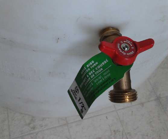
It seemed imperative to change the setup. I had a 220
litre white plastic drum I had cut the top cut off of, which is what
the guy I bought the tilapia from used for tilapia tanks in his
aquaponics setup. I took it inside. Later I drilled a hole and threaded
it for a hose connector type shutoff, about 2/3 of the way to the
bottom. A filter will sit on the floor inside. I want to pump from the
bottom to get waste out, but I don't want the pump to be able to suck
it dry in case of any problem, since that would immediately kill the
fish.
I still haven't got it in operation. If I don't get a move
on, I may soon be mopping up a flooded floor.
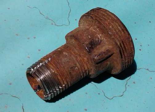 DIY pipe socket threader: a convenient little
iron pipe,
DIY pipe socket threader: a convenient little
iron pipe,
with the threads notched with an angle grinder zip disk
to cut into the plastic.
Thermoelectric (Peltier Module) Fridge & Space Heating Update
(Short version - long report is under "Other" green projects)
I continue to be disappointed by what seems to be quite
a limited lifespan of Peltier modules. The one that had been in the
fridge for some time (a year?) performed worse and worse, and the
fridge
temperature rose gradually from a typical 6°c to almost
11°. And that's at the cool end. The only thing worse than a "Q" of
.8 to 1 is a "Q" that's dropped to .5 or .6. Doubtless for a camping
cooler used for a week or two a year it's fine, or maybe in an electric
vehicle, it's fine, but for full time use,
it's a problem.
Likewise, I wouldn't want to explore thermoelectric space
heating for houses much further as it stands, because the savings in
electricity
would be replaced by the headache and expense of replacing the modules
on a too regular basis. It might still be practical for
electric cars, where any saving in heating electricity reduces the loss
of driving range, and where the unit is probably only used an hour a
day instead of 24.
It turned out to be only partly module degradation. The
other factor was the heatsink had become quite dusty.
Once I had checked out the difference just the
cleaning made - 2 or 3 degrees - I put in a new module. It's now
down to 5 or 6° and the ice tray is
half ice - back to usual performance.
I may try putting in a very large peltier module (I have a
couple of 14
amp ones) and use a DC to DC converter to supply it a lower voltage.
Hopefully being run more gently will considerably extend the life span
as well as increase the coefficient of performance. 8 or 9 volts with
such a high current module should provide more cooling than at present,
probably with no more current. This will of course need a
programmable control. But I don't seem to be finding much time to
take on more projects, even when they're extensions of existing work -
things that 'should' have already been done. Of course, the plan gets
better as I go, so it'll be better if it does ever get done.
So far I haven't seen any sign of higher performance
peltier modules entering the market. A Q-max of 2 to 3 would make a big
difference over .8 to 1... and dropping from there. But I haven't
looked for them for a while.
Solar Hot Water Heating
I gave thought to how to do a solar hot water heater.
Heating water directly with the sun is more effective than making
electricity with solar panels and then heating water with the
electricity. I've thought about various arrangements for the last
couple of years, with pumps and controls and "rubber mat" black
"swimming pool" solar water collectors, and finally concluded that the
best way was exactly the same way I did it in 1979.
The steep 45° roof of my house is pretty much an ideal
average angle for catching the sun. Furthermore, it makes for a
considerable vertical height in the centerline of the attic. A typical
hot water solar collector is 4' x 8', 32 square feet. By making a
collector 2.67' x 12', again 32 square feet, it can be mounted low on
the roof, partly over the eaves. Then, the water tank is mounted on a
stand in the attic, and the entire tank is above the level of the
collector. With a pipe from the top of the collector to the top of the
tank, and another from the bottom to the bottom, the warmed water
circulates by convection, but if the water in the collector is cooler
than the tank, there's no flow. No controls or pump are required,
greatly simplifying the whole thing. With a shallower sloped roof, it
could still work with the tank on its side under the peak. (It can also
be hooked with a similar loop to the woodstove for winter hot water.)
The water circulated freely through the collector and tank.
Two shut off water pipes still run to the attic, in line
to the electric water tank. Copper was used except for the cold water
inlet because of heat concerns. I drained the collector for the winter,
but two problems with the original installation were from water
freezing:
(a) The collector wasn't quite straight and a pipe through it
would freeze in winter and burst even tho it was drained.
(b) the pipes between collector and tank did a short dip down
where they went through the roof, and one of them too froze and burst
one winter.
I finally got fed up with doing plumbing every spring and
took the collector down. It still ran off the woodstove. I had a 12'
loop of soft copper pipe coiled through the stove, and it would
actually boil the water if not enough hot water was being used.
The third and finally fatal for the whole thing problem
was that in about 1984 the galvanized water tank sprung a leak. It had
so much plumbing soldered to its specific four openings that I blanched
at the thought of trying to replace and replumb it. I acquired a copper
water tank not long after that, but the collector was gone and I never
got around to rebuilding the system. So far!
This time I hope to do most of the soldering on the
ground, use plenty of pipe unions, and just bolt it together once the
collector and tank are in place. I think I'll make the collector the
same way as in 1979: enclosed in wood, insulated at the back, copper
pipes with black painted aluminum fins for backing and "glazing"
(hmm... single or double?) of light plastic. A small electric heater in
the bottom pipe of the collector would use minimal power and avoid
having to drain it in the winter.
CRA Paperwork
I worked fitfully on the 2014 paperwork for CRA.
Admittedly I haven't been applying myself very well to this task, but
I'm wondering how it can take longer and longer each year, now for less
and less refund of my considerable investments in R & D. Since they
had complained about my supporting documentation, I put together all
the monthly TE News articles for the four projects I'm claiming into
separate files, along with a daily log and some other material. I was
shocked to discover the projects will take over 100 pages to print out.
June Priorities
* Finish CRA paperwork and submit it ("should" have been done in March)
* Make a NiNi cylindrical battery. (should have been done in May)
* Add 4 magnets to the new Electric Caik motor's rotor (configuration
NSNSNSNS) and reassemble it.
* Get the unipolar motor controller reliably and effectively running it.
* Once those are done, make a magnet sensor for the Electric Weel and
apply the unipolar controller to it.
I'll try to dig into that list, but there are little
diversions like the NiMH batteries for the RX7 EV and trying to renew
(rehydrate?) older NiMH dry cells, LED lights ...and just plain living.
In Passing
(Miscellaneous topics, editorial comments & opinionated rants)
Borax for Arthritis?
This is an idea that may be of interest to the many who
are affected by arthritis. Some recent research has identified the
chief cause of arthritis, as well as of calcium deposits, as boron
deficiency. Many farm soils are becoming deficient in boron and other
trace minerals since only the major fertilizer chemicals are being
replaced. I had heard a couple of people raving before about how borax
has cured their arthritis. That seemed iffy since borax is sold as a
cleaner, surely not for ingestion! After I heard about the studies I
found a couple of types of 3mg boron pills at a health food store. One
was boron citrate, the other, cheaper, brand was boron glycinate. But
it seems sodium borate - borax - is actually the prefered form. And
I've heard from a couple of people that regular grocery store "20 Mule
Team" brand borax is quite pure. On the web I found the recipe of one
teaspoon of borax to a liter of water, with the dose being to drink two
teaspoons a day giving 7mg of borax. Probably just one teaspoon is
better once arthritis symptoms have cleared up. If you just don't trust
that the borax is pure (who could be blamed for that?), the 3mg boron
citrate pill is doubtless the one to use. (An available 700 microgram
boron citrate pill is a pretty low dose, tho the pill also has some
calcium. 3 milligrams seems to be usual, and up to 10mg is often used
for 2-3 months while curing the arthritis.)
Three months of 3mg boron citrate pills seemed to have
have taken away my mostly minor arthritic aches and pains, but a couple
have returned since I ran out 3 weeks or a month ago. So I've just
started with the borax in water.
Apparently boron is best taken with vitamin D and calcium.
(I take 1000 IU/ 25mcg vitamin D every second day anyway, since most of
us on the cloudy west coast are vitamin D deficient, leaving us highly
prone to cancers. Surely there's enough calcium in regular foods?)
Geo-Engineering: Chem Trails!
Last winter mysterious rumbling sounds started up, perhaps
every 20 minutes or less. They sounded like very heavy aircraft taking
off, apparently from somewhere in Washington state (Widby Island?) just
across the strait from Victoria BC. Others across America have been
noticing strange rumbling sounds as well for at least a couple of years
too, to
the point where they were posting about them on youtube. A friend
staying on the west coast of Vancouver Island reported hearing heavy
military jet aircraft flying north, and coming back south sounding much
lighter, week after week. (He thought they must be taking troops and
materiel to Alaskan bases. He was in the forest and couldn't see much
of the sky. He said it was unusually dry, and that the trees weren't
healthy
- the whole vast forest.)
Early in May the same friend, back in Victoria, pointed
out to me aircraft "vapor" trails to the west, drifting eastward over
us. They criss-crossed the sky, and didn't seem to fade but instead
they spread out, until the whole sky had a light overcast. We don't seem to be on any regular
commercial flight routes and jets are only occasionally seen in
Victoria skies. But the trails were everywhere. More aircraft were seen
occasionally trailing another batch. I had seen some similar suspicious
looking cloud formations before but wasn't sure. By month's end there
it happened a few more times. These one could
point to and say "That's just not natural!" It's not random aircraft,
nor just regular vapor trails, and there were lots of them. What could
it be but the chem trails people have been talking about since at least
2010, sprayed by
the heavy planes from Washington state, flying out over the Pacific off
the west coast?
In the next few days, heavy clouds came over but didn't
drop more than a few drops of rain one night. And it's been hot - July
weather in May, when single digit (celsius) nightly lows are the norm!
I had heard of "chem trails" before, but I didn't know
what to make of it. Surely at least this strange idea was the product
of an overactive imagination, not some twisted evil plot? It seemed
absurd to think that those running
our society would permit - or that anyone would want to pay for -
widespread, reckless experiments with the atmosphere that gives us
oxygen, rain and life. Yet... I'm not sure how much central control
there really is. Government has sold out to corporatocracy, and there
seems to be less and less co-ordination of or control over various
mixed agendas. People with power are doing some crazy things, and the
evidence (seen with my own eyes) says there's ongoing aerial spraying
on a massive scale.
The jet stream
that normally flows west to east now typically does a big climb north
over the Pacific, then goes south in the middle of the continent, below
much of the eastern USA, and back up at the Atlantic coast. The last
few winters have been bitterly cold out east ("colder than the north
pole!"), while in the west things have been balmy - and very dry.
California has been having the worst drought "in 12000 years" for four
years, and off the coast of California is where the heaviest spraying
has been done. It looks like this altered jetstream is also sucking the
cold from the arctic, where the arctic ocean polar cap is gone in
summer or nearly so, and the glaciers of Greenland are melting and
flushing out into the Atlantic as fast as the water can flow.
[According to a recent TV documentary by climate scientists in situ in
Greenland] The melting ice and melting permafrost are releasing vast
quantities of trapped methane hydrate into the atmosphere from both
land and sea, and this greenhouse gas is 50 times more potent at
raising temperatures than carbon dioxide. [According to another recent
TV documentary by climate scientists in Alaska] The polar ice cap
reflected away most of the sunlight. The open water absorbs most of it,
so the melting is at this point irreversible. They spoke of a potential
ten degree celsius (!) average rise in arctic temperatures. This is
Earthshattering stuff - much worse than previous "alarmist" predictions
of six degrees by mid century. (Those were for 6° rise in the
arctic, 4° in temperate zones, and 2° in the tropics.)
One rumored rationale for chem trails, if there is one,
has been to 'reflect
away sunlight to cool the Pacific ocean' which keeps producing frequent
warm "el-niño" weather. This has predictably failed as much of
the additional warmth in the Pacific is evidently due to magma
circulating closer to the the crust than usual (also bringing
volcanos), not to sunlight. And
the blanketing effect of the particles may trap more heat than is
reflected away, again making a net warming effect rather than cooling.
The particles high in the atmosphere also inhibit rain. (One military
explanation told to pilots - something about stopping surprise "enemy"
attack flights - is so bizarre as to not just stretch but break
credulity.)
There's a saying "April showers bring May flowers", which
for Victoria BC I sardonically convert to "May showers bring
June flowers" because there's often so much rain through April and May.
This year (and last year) there's been little rain since March. When I
set up the 'reservoir' (inflatable swimming pool) in early March, it
filled with 11" of water in one 36 hour deluge (fed from two sets of
eaves-troughs). Only another 9" was added throughout the rest of March,
all of April, and all of May - most of it in March.
Now, who would go to the expense of buying all these
chemicals - countless thousands of tons, no doubt - for no better
purpose than to play Russian Roulette with the whole planet's
ecosystem? According to at least one internet source, the chemicals are
made from fly ash from coal burning. Apparently it's cheaper for the
coal plants to spray it out of aircraft than to have it hauled to a
landfill and pay to dump it there! So (in twisted corporate minds), why
not see if it can be used that way to improve the climate, perhaps
reduce global warming? With no actual studies, initial or follow-up, as
to consequences. But after all... it's cheaper!
In California the huge agriculture business that helps
feed so much of North America is turning to dust, and 38 million people
could turn on their faucets and have nothing come out in about a year.
(L.A. area tap water may be crappy, but at least it's water - so far!)
And it gets worse. The materials in the fly ash/chemtrails
aren't innocuous. It's apparently causing individual heath problems.
Various metals like strontium and barium have been identified in rain
water and lakes, and more especially aluminum compounds - the major
component. Aluminum is linked to Alzheimer's disease, and probably to
Autism, both of which are skyrocketing. It may be causing skin rashes
and, apparently containing "polymeric"(?) nano fibers (perhaps similar
in size and shape to asbestos fibers?), cancers.
This may - or may not - explain why I myself have been
mysteriously getting itchy as if I had been working under the house in
the fiberglass dust, without changing clothes or showering after, with
little slivers poking through my skin here and there. Like fiberglass,
asbestos, and sometimes fir stickers, they're so fine I can't see them
to remove them. I can only take a razor blade and shave the area. That
way the part sticking out with luck is cut off (or the whole thing is
pulled out?) and the irritation stops or is much reduced. (Hopefully
the remaining bits eventually work their way out.) For a while I was
changing my clothes sometimes almost daily as they so often seem to
have become contaminated. People around here with no prior lung
problems, including me occasionally, seem to have developed a cough.
That part
seems to have stopped for now.
As I first wrote of this on the afternoon of May 21st,
there were
more odd clouds in odd patterns instead of what seemed like it should
be blue sky. I went for a walk and found an unusual afternoon fog over
the strait, somewhat under a single dark cloud jutting from the Olympic
mountains, that seemed fixed in position. I suspected but wouldn't have
sworn the lighter, somewhat linear clouds were chem trails. But my
observant friend, having been where there was a good view to the west,
said they
were spraying all day out over the ocean. It drifts over the
land on the wind. That night there was lightning - usually a once a
year phenomenon in Victoria in July or August (if even once) -- and
yes, lightning has also been said to be an effect of chemtrails, the
aluminum particles increasing the conductivity of the atmosphere. And
again there was no rain.
After adding some rainwater from the 'reservoir' pool to
my tilapia aquaponics tank in early May, a scummy foam covered part of
the surface, frothed up by the aeration spray and general water
circulation. This was quite puzzling, as there had never been foam
before, and I always used rainwater. I didn't know what to do about it.
Apparently the rainwater in
the pond was less than pure! It lasted a few days then dissipated.
Later there was a lesser amount of foam in the large aquarium after I
added just a little pond water to it. If I remember right, there was a
bit of foam on the pool, but not much, perhaps because the calm water
wasn't being stirred up. Luckily it didn't seem to hurt the fish. Am I
digressing here? I'm afraid not!
Late on the 21st, I looked on "Dahboo7's" youtube channel.
Dahboo7 covers unusual news almost daily, or more than daily, with a
separate short video on each
subject. There was one about massive seabird dieoffs along the Pacific
Northwest coast. That led me to another longer news report video about
the same phenomenon, which explained there were [probably tens of]
thousands of seabirds of various species washing up on beaches from
Washington to California, dead or dying. No doubt on BC's west coast as
well. The culprit: scummy foam from "a mystery spill", clearly seen at
the shoreline and on the beaches, was soaking their waterproof downy
feathers and they were getting wet and chilled. The foam immediately
reminded me of that in my tank.
Apparently this "mystery spill" had reached my outdoor pond as well as
the ocean.
Connecting the dots, the source material causing the foam
has
to be airborne. What but countless tons of chem spraying? Is aerial
chem spraying related to other Pacific mass die-offs, such as that of
the salmon(?) that is causing mass starvation and die-off of California
sea lions, or the mass starfish die-off a year or two ago? There I have
less to go on. (I'm sure there were other Pacific die-offs recently
too... what were they?)
You can find out more on the web about chemtrails and
"geoengineering". Especially look on youtube for Dane Wiggington, who
has been trying for some years to alert everyone to chemtrails and
their potential for
ruining the whole ecosystem and even making Earth uninhabitable. He
thinks that if enough people know what's happening, it will stop. The
pilots will refuse to dump toxins on their friends and relatives,
others may refuse to deliver the ash to the airports, etc... and just
maybe those who think they are in charge, whoever they are, will stop
ordering it done. But there are "gag orders" for "national security"
(!?!) on everyone involved, and the pilots are carefully selected for
callousness and are frequently rotated. Of course the "mainstream
media"
will never air anything about it, so it's an uphill struggle.
(Reporting on vast die-offs of seabirds and other creatures is okay, as
long as the root cause isn't identified!)
HAARP Too!
The High Frequency Active Auroral Research Program (HAARP)
in
Alaska uses extremely high powered radio waves from an upward aimed
antenna array to heat the ozone layer, creating artificial high
pressure areas and consequent rising winds that blow the ozone away,
and other
effects from heating the ionosphere. HAARP is apparently responsible
for many extreme weather anomolies, and according to some can even
trigger earthquakes. (This last seems far-fetched to me.) Pictures have
been shown of clouds with big holes punched right through them, and of
various other bizarre aerial phenomena.
And chem spraying, making the atmosphere more conductive,
magnifies the effects of the HAARP signals.
The holes in the ozone layer are killing trees globally by
allowing short wave UV radiation to reach the Earth's surface. (That
was being blamed for mass bee die-offs... but apparently the cause for
these has now been pinpointed as being Monsanto's genetically modified
crops that generate their own insecticides, not HAARP. Monsanto is
playing Russian Roulette with the whole world's food supply, not the
environment!)
The US government says HAARP has been shut down. Hurrah!
What they don't say or comment on is what people are saying:
that as many 18 new HAARP sites, some of them on ships for mobility,
have now been created and are actively interfering with natural
weather. And that's just the US operated ones - they say they're not
the only ones. Again there's more info on HAARP on the web and on
youtube.
Someone showed microscope images of the fibers reputed to
have come out of the sky after chem spraying. There were pictures of
someone with a nasty rash on his shoulders and back, attributed to
them. Someone showed weather
satellite time-lapse images of the western seaboard and pointed out 5
unnatural
weather conditions that he attributed to HAARP and chemtrails, saying
the drought in California was being deliberately created. Many other
videos each paint a tiny portion of a sinister and disturbing picture.
Unnatural Disasters?
Well, the missing rain here on the west coast had to go
somewhere! After the Colorado "1000 year" flood of September 2013 and
now the preliminary flash flooding of San Diego area on the 19th,
seemingly it all came down at once on the 24th-25th (and continuing on)
over the whole
south central USA, washing out roads and bridges and creating disaster
zones here, there and everywhere. Texas is prone to flash floods, but
no one had ever seen water rise so
far so fast as it did in some areas. Oklahoma got 27" of rain in May
(to the 25th) when its annual average is 4-5".
But the USA wasn't the only place hit, and according to
some, it isn't the only place where geo-engineering is going on. It
seems like half the world, in places as diverse as Australia, Europe
and Moscow, has suddenly been inundated. The other half is being dried
and roasted, with Alberta forests burning up and killer heat waves in
India.
The rebalancing of the ocean and the atmosphere to some
new equilibrium could
easily take decades after the "geo-engineering" ends, and in the
meantime extreme weather and climate events will be commonplace.
Globally, powerful earthquakes and volcanos have also become
'abnormally' active in the last few years and may well continue
increasing. Whether this is weather related I don't know. I have a
feeling that the present focus on war and international affairs will
gradually start to give way to internal disasters and damage control
and repair within nations in the coming years and decades.
Sustainability
To outward appearances we are headed for extinction, at
the hands of spiritually and morally blind or defective people with a
lust for power, control over others (to what end?!?)... and
destruction. Some of them seem to actually despise anything having
pristine and natural beauty, impudently not subject to their whims, and
probably take satisfaction when they hear of seabird die-offs and
horrific environmental disasters. A complacent public is allowing it to
happen. Who'd have thought extinction could
be accomplished by hateful people without a nuclear war? What will
become of them
when they have to give an accounting for the mortal lives they lived?
Doubtless many will choose oblivion over eternal life. The coming
collapse of the global financial system, economy, and probably of the
effective operation of governments everywhere, accompanied by unnatural
natural disasters, deprivations, wars and plagues, devastating as
it will be, will be a welcome fresh start for the planet and for
humanity.
The celestials, the spirit beings who manage the universe
and
the planet, and offer us guidance but never interfere with human free
will, are here and ready to assist whenever a human turns his spiritual
side 'on' and follows his indwelling spirit of God's leadings. They say
there are three core values of social sustainability which have never
been applied on this planet and which need to be applied
to every endeavor if stability is to be attained:
1. Quality of Life
2. provision for Growth
3. Equality.
Everything should be judged with
these in mind, and the more people who are aware of them, the better.
For example, war leads to unsustainability just for
starters
because there is no equality between invader and invaded. Uncontrolled
population growth and genetic degradation lead to unsustainability
because they lower the quality of life for everyone, while a reasonably
sized and genetically improving population will have a higher and
rising quality of living, over their increasingly lengthy lives.
Uncontrolled population growth is always followed by periodic disasters
with huge die-offs not only of wildlife but of the human population,
and it has been seen many times throughout human history - but never
before on a global scale.
One can easily see that most of our present institutions
don't take these three core things into consideration, and need to be
modified or replaced. But they say that the Earth's peoples can all
agree on these three things even if various groups will disagree on
most everything else.
To accompany those, there are three core value-emotions:
empathy, compassion and love.
One sees that our governing institutions were solidified in form
a hundred years ago and more, and that they are little changed in since
then spite of the whole of society and life changing around them. They
were created without provision for growth, so they are stuck in the
past and increasingly unable to cope with modern realities. That there
should be mass protests and riots in democratic nations shows that the
will of the people isn't being reflected in the operation of their
governments.
In my own ideas for a government Department of Progress,
for citizen initiated referendums and for an "Election Central" forum,
one can see that the aims are for provision to allow political
institutions to grow and adapt, and for improved equality, on many
levels, to the end of a better quality of political and social life.
Tolerance, respect, peace, enlightened social progress
and other attributes and blessings - eventually utopia on this
beautiful and "exceptionally diverse" world - will gradually
accrue from wide observance of these three core values.
Newsletters Index/Highlights: http://www.TurquoiseEnergy.com/news/index.html
Construction Manuals and information:
- Electric Hubcap Family Motors - Turquoise Motor Controllers
- Preliminary Ni-Mn, Ni-Ni Battery Making book
Products Catalog:
- Electric Hubcap 7.2 KW BLDC Pancake Motor Kit
- Electric
Caik 4.8 KW BLDC Pancake Motor Kit
- NiMH Handy Battery Sticks, 12v battery trays & Dry
Cells (cheapest NiMH
prices in Victoria BC)
- LED Light Fixtures
(Will accept BITCOIN digital currency)
...all at: http://www.TurquoiseEnergy.com/
(orders: e-mail craig@saers.com)
Daily
Log
(time accounting, mainly for CRA - SR & ED assessment purposes)
1: Worked on Electric Weel - improved rotor mounting
2:
3:
4: Finished April newsletter (TE News #87)
5: Worked on Electric Weel - revised & finished rotor mounting
6:
7:
8: Weel - assembly and adjustments
9: 10: weekend
11: Weel - assembly, adjustments
12: Etched a piece of cupro-nickel for a battery electrode/test.
13: Weel: added ribs to strengthen body side of stator and to mount
unit in hydro power assembly.
14: CRA paperwork for 2014.
15: Weel: Inspected and adjusted. Improved power per RPM readings but
they're well below the expected range. (Unsatisfactory. Now what?)
16:
17:
18: Etched a second piece of cupro-nickel, this time with agitation
attempting to prevent discolorations (contaminations?). Had idea to
turn generator into an "active" generator using the unipolar/switched
reluctance motor controller. This should save the project!
19: Turned a piece on lathe to make a tiny sheet metal roller for
cylindrical (outer, negative) battery electrodes.
20: Inspected, cleaned and re-installed thermoelectric fridge's cooling
unit, which was gradually losing its cooling power.
21: Inspected thermoelectric fridge and cleaned cooling unit.
22: Replaced peltier module in fridge. Made flat drive belts from
polypropylene strapping to test the idea. (hold at least 200 pounds.)
23:
24:
25: CRA Paperwork
26: Soldered together a battery pack with "Sub-C" batteries.
27: Re-adjusted Weel generator (plastic bends!); turned shaft for
(battery electrode) sheet metal bender; Installed "hose faucet" onto
new tilapia tank drum.
28: finished sheet metal roller and rolled a piece of cupro-nickel for
a NiNi battery electrode. CRA Paperwork.
29: Made another battery pack with sub-C cells, and 6 tube batteries of
12V, 10AH D cells.
30: Removed two tube batteries fron RX7 EV, swapped 5 tubes from one
tube battery and added one to the other - now both 100AH, 12V and
stronger. Re-installed in car. Hopefully driving range will be extended
a couple of miles.
31: Test drive. Battery stayed higher - better than previously 2nd
weakest.
Electric Hubcap Motor Systems - Electric Transport
Electric
Weel Motor (Generator)
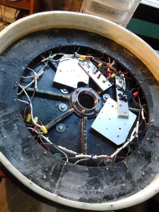 Stator with coils wired up and with alternator
diodes thrown in.
Stator with coils wired up and with alternator
diodes thrown in.
(I doubt if those plates will be sufficient heatsinking for continual
use.)
The Weel came together, but not without some
teething problems. The huge diameter, with the body held together at the outside rim, greatly
exaggerated dimensional issues that were only of minor concern with the
smaller motors. 2
or 3 millimeters of flex at the bearing holders in the center top and
bottom became 6 or 8 in spite of some reinforcement. The "impact
modified acrylic" ("like lexan") rotor too
seemed adequately strong but it wasn't 100% stiff even with the glued
reinforcing/thickening pieces.
When it was assembled, either it would seem there was
excessive flux gap or the rotor magnets would rub on the center wall.
Or both.
The center
hole on the rotor side, and its 6 bolt holes,
were all enlarged with a file so the bearing could be moved around, its
position adjusted. Later, 4 threaded holes were put through from the
stator side to allow
long bolts (actually threaded rods with a wing nut tightened against
another nut) to press against and hence adjust the position of the
rotor. Then the top could be put on and the bearing assembly tightened
with the rotor presumably already in position.
When all this was worked out on a Friday, the rotor could
be adjusted and the machine turned freely. But the next morning, the
rotor was rubbing somewhere, and by Monday it was stuck solid. The body
not only bent under the pressure of the rotor's magnetic attraction to
the stator, but gradually deformed. I had noted that before, but I had
been hoping it only happened for a week or so after molding. This had
been molded months ago. Again, the small effect was magnified with the
large diameter.
On the 11th and 12th we cut and attached two heavy
aluminum channel bars, with 6 bolts through each to the stator end of
the body, forming two ribs to give the body more rigidity, and to mount
it into the hydro power transmission. This - pretty much - solved the
problem of flexing and deformation. It would turn freely with a spacing
washer inserted, but the alignment wouldn't stay without one. One
problem for testing was that the top cover didn't have enough bolts
(four short test bolts instead of 24 longer ones) and it shifted around
a bit, which of course changes the shaft alignment.
I gave it another try on the 14th. I lowered the rotor to
the lowest and adjusted it carefully. I drilled a small inspection hole
in the lid. As I observed the rotor go by, it seemed even enough. But
it would rub at one point in the rotation, so there was definitely a
lower spot, if only by a bit. I marked it with a felt pen to put in a
piece of cardboard or paper as a shim. The open circuit voltage was up
to 4.5 volts at 60 RPM, and it looked like the current would have gone
to 6 or 7 amps at 60 RPM if I had been able to turn the shaft that
fast. As it was it was about 3 amps at under 30 RPM. Well, at least the
maximum power point would be up to 2500 watts or so at 600 RPM. At
least 4 times as much would be a lot better! And later, it had deformed
enough that it was rubbing again.
On the 27th I drilled a hole in the side and found the
rotor dipped down on one side during rotation - about 1/8 to 3/16 of an
inch wobble was much easier to see from the side. I tried a couple of
shims to even it out. One (electrical tape) seemed to do nothing, the
other (thin plastic strapping) pushed it much too far the other way.
Somewhere I'll get it to the middle and then it should run freely at
the smallest flux gap easily attainable. (That's where the rotor
assembly on the shaft rests on the lower bearing with no spacer washers
between.)
Major Problem: Insufficient Output!
Unfortunately, I had never worked out just what voltage it
would generate at what speed. There just seemed to be too many
variables, and of course nothing is set up for this type of machine
construction. (If anyone can find "toroidal iron powder donut coils",
"ilmenite" and "paramagnetic materials" used in
a motor design book, I'll eat my hat!) But with 8 coils in each phase I
anticipated it would be somewhere in a good range. If it was too high,
the coils could be broken up into parallel sections to get higher
amperage instead of higher voltage.
One could spin it up to 60 RPM by hand, and with the heavy
rotor, the speed could be kept steady enough to get meter readings. The
cogging was surprisingly low - hardly evident. To our surprise it put
out less than 3 volts DC. Later, with better adjustment of the rotor
position, it was still only 3.5 to 3.75 VDC. With such low voltages,
even the 1 volt or so losses through the rectifier diodes were
significant. I checked over the wiring, then put in some extra wires
temporarily to measure at different points. From each phase end to the
"Y" point was around 1.7 VAC, all very close to identical, ditto for
3.0 VAC between any two phases. If I shorted the DC output I measured
about 3.3 amps at 50 RPM, which was as fast as I could turn it when
shorted. Of course, even with the huge diameter 60 RPM is awfully slow,
equivalent to only 160 RPM for the Electric Hubcap size. The Electric
Hubcap doesn't put out much voltage at that speed either.
To get even a basic 12 volt battery charging system it
would have to put out 15 volts. Allowing for constant diode voltage
losses, and trying to estimate a maximum power point below the open
circuit voltage, I estimated that it would need to spin at somewhere
around 250-300 RPM, at which point it might put out 15 amps, for a mere
225 watts. At 600 RPM (probably a reasonable maximum), it might be
around 33V @ 33 A or 1000 watts. This is hardly 12+ KW territory! If
the coils were rewound with more turns of finer wire, they'd produce
more voltage, but presumably with correspondingly decreased current
capacity. A smaller flux gap would produce higher voltage and power
per RPM, but the minimum flux gap is enforced by the need to clear the
center wall, which the rotor rubs on as it is unless carefully
adjusted. The flexibilities in the construction, and the design itself,
work against it. And
the cogging gets bad at smaller gaps anyway.
Apparently my "Electric Hubcap" construction makes much
better motors than it does simple generators! One could make a more
complex generator by using a motor controller with it in "regenerative
braking" mode. A range of output voltage and power would then be
available, "maximum power point" adjustment for the conditions. But we
put in 32 magnet poles instead of
16, and it couldn't be run as a regular BLDC motor that way - as I
found out in 2008,
the magneto-motive forces in each direction cancel out in this
"generator only" configuration.
But this seemingly unfortunate circumstance led to the
realization that the "unipolar" type of motor controller would work.
With this very 3 to 4 coil to magnet ratio that seemed all wrong, an improved
type of BLDC motor can be created with the improved motor controller.
That seemed like a great concept, so I've written it up in "Month in
Brief".
Making Flat Drive
Belts from Polypropylene Webbing/Strapping
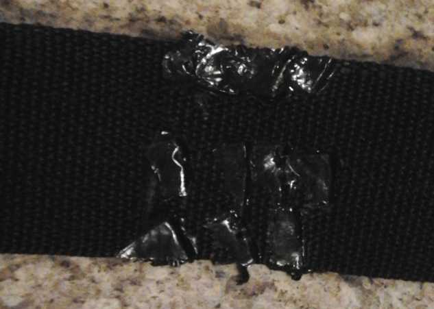
Welding the seam to form a flat belt:
strap ends together - hot iron - cellophane
I've thought now and then of flat transmission belts on
slightly convex pulleys. Wikipedia says that with modern materials
they're nearly 99% efficient and that a 1" wide belt may transmit up to
100 horsepower. And they can be de-tensioned and slipped for a clutch
action, unlike chains and toothed belts. But when I tried to find flat
drive belts on line, they hardly seemed
to exist.
It occurred to me that one might make flat belts using
flat polypropylene or other strapping, which comes in various widths.
But how to make a length of it into a loop that wouldn't break at the
seam? On the 22nd I was uncrateing a "portable heat pump / air
conditioner" I bought for the house, on "sale" at Costco for 400$. The
straps around the box were completely unyielding and had to be cut with
scissors. The ends were melted together for a couple of inches.
This was a means I had vaguely considered. Now I made it
an
experiment. I got a length of 2" wide PP strapping and cut a couple of
pieces of cellophane. My dad used to make ice fishing enclosures, clear
"tents", by
putting cellophane sheets over and under polyethylene plastic and
melting two pieces of
plastic together with an iron to join them. I put down a piece of
cellophane, then
the ends of the strapping on top of it with only about 3/8" of overlap,
then another piece of cellophane. When the iron was hot I applied it
and after a couple of tries and then flipping the belt over to heat
from both sides, I melted
the seam. It made a bit of a lump that wasn't very flexible, but it
wasn't bad.
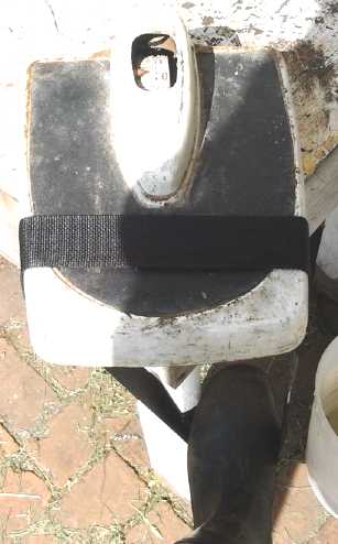 When it was
cool it tried to pull it apart. It didn't
break. I put a weigh scale on the corner of a table and looped the belt
over it, so I could push down with my foot. (The picture is worth many
words.) I put my full weight on it, then jumped up and down a bit.
Apparently it will hold at least 200 pounds or thereabouts. I had
thought it would break at some point and a longer overlap
would be required. I managed to break it by putting it around my knee
and pulling it with my fingers at one edge instead of uniformly
centered. But it wasn't easy. It broke along one edge of the seam where
the single layer had been weakened at the edge of the melt, so the
length of the overlap was irrelevant. The next two seams failed. I
didn't apply enough heat for long enough to melt through to the middle
nicely. The
fourth one, heated longer, held and I was unable to break it by hand,
period. The 3/4"
fairly stiff seam would have been rough going around a small pulley,
but again it seemed it didn't need to be so long. 1/4" would probably
be fine. I'm calling it a success. The rest of it is so limp compared
to most any other drive belt, I can see why it might be 99% efficient.
When it was
cool it tried to pull it apart. It didn't
break. I put a weigh scale on the corner of a table and looped the belt
over it, so I could push down with my foot. (The picture is worth many
words.) I put my full weight on it, then jumped up and down a bit.
Apparently it will hold at least 200 pounds or thereabouts. I had
thought it would break at some point and a longer overlap
would be required. I managed to break it by putting it around my knee
and pulling it with my fingers at one edge instead of uniformly
centered. But it wasn't easy. It broke along one edge of the seam where
the single layer had been weakened at the edge of the melt, so the
length of the overlap was irrelevant. The next two seams failed. I
didn't apply enough heat for long enough to melt through to the middle
nicely. The
fourth one, heated longer, held and I was unable to break it by hand,
period. The 3/4"
fairly stiff seam would have been rough going around a small pulley,
but again it seemed it didn't need to be so long. 1/4" would probably
be fine. I'm calling it a success. The rest of it is so limp compared
to most any other drive belt, I can see why it might be 99% efficient.
One thing left to try would
be to spray it with polyurethane. That should give the surface more
grip. Note also that slippery-smooth pulleys wouldn't be the thing to
use either. Something rough sanded or textured, or a surface material
with grip to it, would be the thing to use. In a bandsaw, where the
band/blade has this sort of flat belt arrangement, the (slightly
convex) wheels have polyurethane "tires" (a relatively fat flat belt of
polyurethane that fits tightly around the pulley) to give the pulleys
more grip.
This nagging point about flat belts and their availability
is now reversed: a flat belt is easy to make and cheap. No worries
about where to get one of the size needed. (Any advantage or purpose to
a mobius strip?) The slightly convex pulleys can be
made perhaps even on a wood lathe. (not to mention 3D printed.)
Furthermore, instead of having to disassemble something complex or
awkward to get a belt on or off, it could be pulled through as a piece
of strapping and then the seam could be sealed in situ. I could
see creating some sort of special handheld "belt seam welder".
A flat belt is the plan for connecting the generator to a
vertical axis wind turbine, with a speed-up ratio to turn it faster
than the turbine. No noise, hardly any losses, and the generator can
turn at a higher RPM than the turbine. But I think for a first real
test I'll change the V-belt on my bandsaw to a flat belt and see how
that works.
"Green" Electric Equipment Projects
Thermoelectric (Peltier Module)
Fridge & Space Heating Update
I'm disappointed by what seems to be quite
a limited lifespan of Peltier modules. The one that had now been in the
fridge for some time (a year?) performed worse and worse, and the
fridge
temperature had risen gradually from a typical 6°c to almost
11°. And that's at the cool end. The only thing worse than a "Q" of
.8 to 1 is a "Q" that's dropped to .5 or .6. Doubtless for a camping
cooler used for a week or two a year it's fine, but for full time use,
it's a problem.
Likewise, I wouldn't want to explore thermoelectric space
heating much further as it stands, because the savings in electricity
would be replaced by the headache and expense of replacing the modules
on a too regular basis. But again, it might still be practical for
electric cars, where any saving in heating electricity reduces the loss
of driving range, and where the unit is probably only used an hour a
day instead of 24.
On the 21st I went to replace the peltier module. When I
took the unit apart, I found the fan and heatsink were rather
clogged with dust. So I cleaned them off and
replaced the same module. The temperature dropped a couple of degrees
to about 9. If I increased the fan speed - which gave it an annoying
buzz - it went down to 8.
Apparently it was partly module degradation and partly
just being dusty, and obviously higher fan speed helps. A filter over
the fan intake might help with the dust; maybe a piece of furnace type
air filter - if it's cleaned regularly.
The next day, having checked out the difference just the
cleaning made, I put in a new module. Soon I could feel frost on the
copper coldness transfer bar instead of just condensation. The
temperature didn't seem to go much below 8 after a couple of hours, but
ice was forming on the bottom of the ice tray for the first time in
ages. By the next morning it was down to 6° and the ice tray was
half ice - about the best I usually get with an 8.5A/15V peltier
module. On the morning of the 25th and beyond, even with the
fan on lower speed, the temperature was around 5° and the tray was
over 1/2 ice. Even the heatsink felt cold. During the day, this
rose to 7 and the ice melted. Upping the fan speed somehow only seemed
to make it worse, or at least no better.
For a while I thought the peltier module worked
considerably better at the lower nighttime voltage (~11.7) than when
the solar panels bring it up near 14 volts during the day. But it
turned out the Chinese control I had installed was actually turning it
off, owing to the temperature sensor having fallen into the cold
condensation water under the ice tray. I moved it.
Since it's hard to find peltier modules with a slightly
higher voltage spec that are more in their highest Q range around 11-14
volts, one thought that does occur to me (I may have already written
this) is to put in a very large peltier module (I have a couple of 14
amp ones) and use a DC to DC converter to supply it a lower voltage.
Hopefully being run more gently will considerably extend the life span
as well as increase the coefficient of performance. 8 or 9 volts with
such a high current module should provide more cooling than I'm getting
now, probably with no more current. The voltage should be on a
programmable control. But I don't seem to be finding much time to
take on more projects, even when they're extensions of existing work -
things that should have already been done. Of course, the plan gets
better as I go just in case it does ever get done.
Finally, also on the 21st I got a "portable heat pump /
air conditioner" at Costco, on "sale" for 400$. Instead of being a
window mounted unit, or a two-piece unit that has to be installed and
connected by a refrigeration professional, this one simply sits on the
floor and there's something like a dryer hose to stick out the window
to vent the outdoor air. At first this seemed like a much superior
arrangement, especially for "DIY", which is made trivial. The heating
mode is "11000 BTU". This worked out equivalent to a 3200 watt heater.
It says it draws "10.3A" in heating mode, which is 1236 watts. That's a
"Q" of 2.6, or 2.6 times as much heat as an electric resistance heater
using the same amount of electricity. For cooling, it's "14000 BTU" and
"11.9A", for cooling worth 14000BTU*.293W/BTU=4100W and hence a "Q" of
4100W/(11.9A*120V)=2.87.
Presumably the heat or cold made by the unit is expelled
outside.
But herein lies a design problem: the hose vents outside, but if air is
vented outside, it has to be replaced by air coming into the house from
somewhere else. It might be better to have two hoses, in and out, but
it has no provision for a second hose.
Otherwise, a heat exchanger for incoming air would be desirable.
Costco said this was the first time they had got a unit
that was a heat pump as well as an air conditioner, and it was the
first time I had ever seen a "portable" one. (I suppose one could
install a window mount air conditioner backwards.) There were two
purposes to buying it. First was the
actual electrical savings potential. If it was being fully utilized as
a primary
heat source, the electrical savings would reach its purchase price in
as little as 4 months of cold weather. (I mostly heat with wood,
relatively abundant around here, but it's a big house and a number of
electric heaters are required. Especially the machine shop is too cold
to work in on cold days in the winter, and it takes considerable heat
to
warm it up.) Second was to inspect the various heat exchange
components,
radiators and fans, and their design and implementation. If I do do a
thermoelectric heat pump, this unit seems to be really well set up...
depending how noisy it is - I haven't turned it on yet. But it has big
"squirrel cage" fans like small furnace air duct fans, that probably
aren't as bad as blade fans.
So far I haven't seen any sign of higher performance
peltier modules entering the market. A Q-max of 2 to 3 would make a big
difference over .8 to 1. (and dropping from there!) (I hope the
researchers or makers aren't being paid off or manipulated to hide them
by a maker of
compressor fridges! Remember Electrolux bought the Einstein patent to
prevent compressorless fridges from being made, at all, through the
1930.s and 40.s when they'd have found a large market.) But I haven't
looked for them for a while.
Electricity Storage
Turquoise Battery
Making Project
Cylindrical Battery
I said last month that the 70:30 cupro-nickel showed no
sign of copper's orange color. But when compared to other metals, or in
just the right light, it's faintly there. There's no question tho that
the silvery nickel color is dominant.
In spite of meaning to make it a priority, I didn't get
much done.
Bizarrely (not withstanding my cluttered rooms) I couldn't find the
center electrode press I made in April. Since I thought for a while to
roll the outer cupro-nickel sheet around the inner pipes, I was missing
the part/jig for making both electrodes. On the 18th I found it in a
cupboard where I keep some battery making supplies including the carbon
rods, which "should" have been one of the first places to look...
occasionally I actually put something away!
The construction puzzle
There were a couple
of pieces to the puzzle that weren't falling into place. One was how to
connect the negative electrode to the outside world. There were some
ways like riveting pieces of metal together or having a tab extend from
the cupro-nickel piece to attach to a screw, that seemed unworkable
because it would be difficult to impossible to assemble the cell. A tab
could simply come out the top at the edge - but that would be hard to
seal, and might eventually break off. (Okay for a prototype, not for
production!)
Of various unsatisfactory options, I decided to screw in a
small bolt/machine screw in the bottom center from the inside, with a
tab of metal attached that ran from under the bolt head to the edge and
then up the side all the way to the top - a friction fit. From there it
would be bent outward so it could be gripped while sliding the
electrode assembly in, then the excess would be cut off. Some separator
material could keep the center electrode from shorting to it at the
bottom. Silicone RTV would be squeezed into the bolt hole before
screwing the bolt in to (hopefully!) ensure a seal.
A piece of plastic could be placed over the bolt on the
bottom to prevent the center electrode from touching it. The center and
outer electrodes would be assembled evenly
WRT heights. The separator material would extend past the electrodes
both top and bottom, and would be scrunched inward over the ends. After
pushing this assembly into the PVC pipe and cutting off the excess side
tab, the plastic top disk would be pressed over the carbon rod and
glued to the outer PVC. (Alternatively the carbon rod could be inserted
last. This would allow its original metal top piece to be retained.)
Then there was the compaction of the 'posode'. I
eventually realized that instead of having a pressing pipe fitting
around the center rod (for the hole for the carbon rod), the electrode
should extend a little past the rod at the bottom. In theory then, if
it was to be compacted in one pass, the center rod should be cut to
length, and a solid die should press the material in, "upside down".
The press would stop a little above the rod when the material was fully
compacted. This would assume the electrode would compact evenly along
its length, which would probably be based on highly polished surfaces
of the center rod and the inside of the outer pipe, to allow the
material to slide along. This would be predicated on using stainless
steel, or the smooth polish might soon be rough rust after a few uses.
I note the center rod should end in a taper to prevent
buildup of material between its end and the die, giving a "false"
pressure reading higher than the electrode material as a whole. (Unless
the carbon rod is to be sanded to the same taper, this will mean a
hollow cone below the carbon rod in the cell. Hmm.)
I cut the center spike to the length on the 18th, for the carbon
rod from an "F" cell. (Those are the ones used in 'square' 6V lantern
batteries, a little longer than a "D" cell.)
If the cells are indeed to last 'forever', they will
eventually dry out. NiMH dry cells seem to do so over just a few years
as noted in the RX7 EV in previous issues (and elsewhere - and in spite
of having no carbon rods), and carbon rods in batteries are said to be
slightly porous and cause drying out. If a small hole was drilled in
the plastic top piece, a syringe could add a bit of liquid at any later
date. To seal the hole, a metal screw would probably corrode, so a
nylon screw could be used.
Since the cell casings are plastic, and since the
electrolyte is much safer than acid or highly caustic alkali, I think
I'll just ignore safety venting as is usually used in rechargeable
cells. On excessive pressure buildup resulting from strong
overcharging, the cells will doubtless simply spring a leak along the
top seam or beside the carbon rod. At worst the plastic top would pop
off - or the bottom, or the outer case would split, but those all seem
unlikely (especially the last with 300 PSI water pipe PVC shells) and
anyway should pose little danger.
Negode
I cut a piece of cupro-nickel sheet, and on the 12th I
taped over one face and put it in a container of ferric chloride for an
hour. It came out rather splotchy looking. Some crap, clear crystals,
that didn't seem to wash off easily were here and there. The various
colors must be impurities from the ferric chloride - copper and iron
compounds. They don't seem to wash off. Considering the splotchy
results with the nickel-brass as well, it looks like I should agitate
the solution, perhaps continually, while etching. Going away for an
hour is easier. An aquarium bubbler might work.
However, the previously shiny smooth surface had a dull
"matte" appearance. It looked like sandpaper under 40x magnification.
The uncolored parts looked like pure shiny nickel grains. The size of
particles making up larger agglomerations extended to as fine as I
could make out, say one micro-meter size. The roughest parts were even
undercut, leaving filaments of nickel up in the air or nearly so, and
perhaps held mainly by other filaments. Very fractal!
On the 18th I etched a second piece. This time I agitated
it continually by hand so it wouldn't come out splotchy, and knowing
that agitation speeds up the reaction, I only etched it for 15 minutes
instead of an hour, still at room temperature. It still came out
splotchy, but not half as bad as the first piece. Under the 40x
magnifying glass, the surface roughness looked at least as good.

First (r) and second (l) etched pieces of cupro-nickel
(The black spots are just shadows - splotchy window)
Rolling up the negode sheet
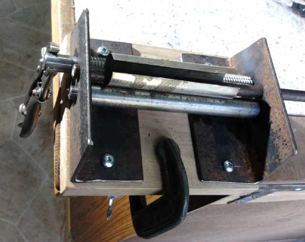 On the 28th I
made a mini sheet metal roller for this. I wasn't 100% sure what I was
doing and I looked up some details on the web, but I think it would
have turned out better if I hadn't. I made two rollers from 5/8"
shafts, turning the ends down to 3/8" as axles. One I left 1/2" and
made it longer to attach a handle to. (I used a small pair of
vise-grips for a handle for now.) This one was a threaded shaft, and I
hoped that would give it more grip on the metal. I ended up scoring
some lines along it with the angle grinder, and then sanding it on the
belt sander with very coarse (#40) sandpaper, to roughen it up. It
helped some, but the sheets still don't roll through readily. The
second roller was smooth. The third one was a spike that was 3/8"
diameter. This can be inserted and removed from its 3/8" axle holes.
Since the piece wraps around it, it needs to come out to remove the
finished piece. To start off, a thinner rod is inserted here which does
a shallow bend, then a medium piece. This is in lieu of having to be
able to move the whole third axle up and down to adjust for each pass.
On the 28th I
made a mini sheet metal roller for this. I wasn't 100% sure what I was
doing and I looked up some details on the web, but I think it would
have turned out better if I hadn't. I made two rollers from 5/8"
shafts, turning the ends down to 3/8" as axles. One I left 1/2" and
made it longer to attach a handle to. (I used a small pair of
vise-grips for a handle for now.) This one was a threaded shaft, and I
hoped that would give it more grip on the metal. I ended up scoring
some lines along it with the angle grinder, and then sanding it on the
belt sander with very coarse (#40) sandpaper, to roughen it up. It
helped some, but the sheets still don't roll through readily. The
second roller was smooth. The third one was a spike that was 3/8"
diameter. This can be inserted and removed from its 3/8" axle holes.
Since the piece wraps around it, it needs to come out to remove the
finished piece. To start off, a thinner rod is inserted here which does
a shallow bend, then a medium piece. This is in lieu of having to be
able to move the whole third axle up and down to adjust for each pass.
I thought I constructed it pretty well, but it didn't work
well and I wasn't really satisfied with the final result. I may redo
the flat end pieces to change the relative positions of the rollers. If
the handle roller and the top roller almost touch each other, the piece
can be inserted and much of the bending done by pushing the piece
around the top roller by hand, without even trying to roll.
In the meantime, the metal piece fits all right in the
plastic pipe. Good enough for now!
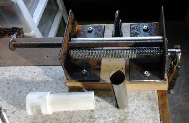 Another view, with rolled piece.
For now small visegrips are the crank handle.
Making up NiMH "sub-C" power tool
batteries, Electric Mazda RX7 "D" cell pipe batteries
I have been using NiMH AA batteries to replace dead NiCd
batteries in cordless drills. The high rate AA cells provide sufficient
current. One could almost squeeze two AA cells in for each original
power tool cell, and this would give perhaps similar current drive to
the originals even with regular AA cells, with at least double the
rated amp-hour
capacity. The problem is that although they are in fact smaller and
lighter, AA cells are somewhat longer. One set can be stuffed in with
room to spare, but two sets won't quite fit.
After all this time, it finally occurred to me that
all-battery.com / tenergy.com have quite an assortment of odd size
cells. I measured the original cells from a dead cordless drill, and
checked. A size called "Sub-C" was the same height and only a
millimeter
larger diameter. I judged that I could squeeze them in and I ordered 52
- two sets of 15 for the dead 18 volt drills, two sets of 8 for "9
volt"
(really 9.6 volt) drills, and 4 because I can't add... I mean, 4 for
spares. (There was a price break at 50 anyway.)
They arrived on the 26th and I spent a couple of hours
soldering up a set for one 18 volt drill. With wires instead of thin
tack welded straps it didn't quite fit in the case. But I got the
screws most of the way in and by adjusting the click-in things a bit
got it to stay in the drill. It seemed to have more power (as best I
can recall) than the original NiCd.s. According to Tenergy the 30 amp,
3.0 amp-hour cells should
also have 40% longer running time. I noticed that most of the cells
seemed badly discharged. A few were slightly below the recommended 1.0
volt lower limit, and many were hardly above it. I guess they don't
sell many sub-C cells and they had been sitting around quite a while.
I hadn't planned on doing another drill immediately, but after
measuring the remaining cells on the 29th I immediately put 4 on the
charger and soldered together another 8 for the 9.6 volt drill battery,
also to put on charge ASAP, replacing the weak regular AA cells I
originally installed maybe 7-8 years ago with the new sub-C cells. FWIW
this was my first soldered together NiMH battery, and also my last
remaining one with no protective wrappings around the cells.
What's the difference between a cheap cordless drill and
an
expensive one? I think it's mainly the batteries. The 9.6 volt drill
was given to me with some dead NiCd.s in it, and I got the 18 volt NiCd
drill for 20$ at XS Cargo. After a few weeks of considerable use, it
lost its ability to hold charge, and I was given another one that had
quit
working too. The NiMH sub-C cells were 2.53$US each, so 15 cells for
the one drill and 8 for the other were about 40$US and 20$US
respectively. These "cast away" cheap drills now perform like the best
ones.
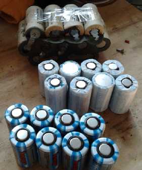 Again these
Tenergy cells, tho obviously they would be used for
battery packs, have only thin plastic insulation which will melt if
overheated and short out the cells, causing a "meltdown" of the battery
and potential for larger disaster such as a house fire. I wrapped each
one with masking tape before soldering them together. And I decided I
should
write to Tenergy and suggest they provide a battery pack making
instructions page that mentions this, even if they don't put a
cardboard wrapping on the cells themselves.
Again these
Tenergy cells, tho obviously they would be used for
battery packs, have only thin plastic insulation which will melt if
overheated and short out the cells, causing a "meltdown" of the battery
and potential for larger disaster such as a house fire. I wrapped each
one with masking tape before soldering them together. And I decided I
should
write to Tenergy and suggest they provide a battery pack making
instructions page that mentions this, even if they don't put a
cardboard wrapping on the cells themselves.
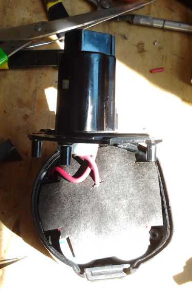 L: Soldering up the cells. The can side took a
surprising amount of heat and I turned the soldering iron
L: Soldering up the cells. The can side took a
surprising amount of heat and I turned the soldering iron
temperature up well over 700°f so I could solder them quickly
without heating up the whole cell.
R: With a piece of tarpaper inserted to ensure the top cell doesn't
short to a lower one, it's ready to close.
Now on to the Mazda EV batteries, "D" cells. When I drive
"longer"
distances (like, up to 7 miles, 11Km) it's always the same oldest NiMH
battery (originally 90AH) that gets low first, and I'm anxiously
looking at the meter and
easing off the pedal trying not to have it go below 10.0 volts. One of
the two that used to run low early seemed improved by the extra 10
amp-hour set piggybacked on top of it, but this one didn't seem
impressed
even with an extra 20 amp-hours (for 110AH). The cells seem to lose
current drive
more than storage capacity over the years, probably because of gradual
drying out of the electrolyte. (And the Mazda taxes the current
capacity of "mere" 100 AH batteries, which seems to be the biggest
factor in the very short driving range.)
This is one of the two "giant flashlight tube" batteries
composed of PVC "1.25 inch irrigation pipes" tied together, both in one
wooden box. (Nine pipes
of ten batteries made 90 amp-hours at 12 volts. This was increased to
100/110 by piggybacking 3 extra sets on top.) I got the idea to
exchange 1/2 the pipes for pipes with new cells to help take the load
better. That would increase the overall driving range, maybe to 10
miles, 16Km. (Now I can look anxiously at some other battery's meter -
including the lithiums and the four remaining lead-acids.)
I have been "down on" the pipes type for some time now,
partly because they take extra space, but mostly because the glued ends
seemed to break loose too easily, disconnecting the cells inside. But
it has
occurred to me this is the same problem as soldered cells tied together
by fat copper "bars". It's the inflexible bars that put the stress on
the joints, breaking solder joins... or the pipe ends... loose.
If I replaced the copper sheets and bars with flexible
wires - at least on one end - it would probably solve the problem. This
month the storage capacity seems to be following the current capacity
downward - possibly because of the repeated voltage drops owing to the
latter. So I decided I couldn't keep putting it off. I made 6 tubes, 60
cells.
And when you think everything's set... the two pipes I pulled down and
cut up to make the tubes didn't fit the end caps. They were the same
brand and everything, and I've used up a dozen pipes from more than one
store, and the caps are cut with the same hole/circle drill, and the
fit has always been the same: the end caps fit tight enough, but only
just. This time I had to sand the end caps down in diameter a bit to
get them to go in. What's different?
I put in 5 new tubes and 5 old ones. I took the copper
plates off one side and replaced them with flexible stranded wires. I
didn't find any loose end caps until I got to the second battery. But
that tube was fully charged so it must have been making contact
anyway... at least some of the time. (Just a couple of times the second
battery got low faster, which may indicate that that set wasn't
helping on those occasions.)
When taken out of the car, all the tubes read 13.72 volts,
but 4 of
them were down to 13.4 or so in 1/2 an hour or less, while the others
stayed up. I guessed that these were dragging the whole thing down a
little, and that one cell in each pipe was weak. Perhaps here is an
advantage to the pipe type of battery: the soldered together batteries
would have to be unsoldered to determine if any cells were bad.
Of course I put the better tubes back in. I put the 6th
new tube in
the other battery so it wouldn't need anything piggybacked on top to be
100 amp-hours. (Since the piggyback sets fit under the hood, I knew
there was sufficient height to add a row - with one tube connected to
the lower battery and one to the upper.) And I found one tube in that
battery getting lower faster, so I put the 6th better tube from the
first battery into it. Four weaker tubes and the three
piggybacked "quintos" sets were left over.
With NiMH.s in pipes, each individual cell can be accessed
by prying
off one of the end caps, and one bad cell doesn't mean the whole tube
is bad.
The next morning, one of the four removed pipes and one
set of
quintos pipes had dropped below 13 volts. I broke the long pipe open
and found just one cell of the ten wasn't holding its charge. In the
quintos, four of 5 pipes of two cells were fine and again it looked
like one bad cell in one pipe. The weak/bad cell in the long tube had
melted insulation, so it had been badly overheated at some point in its
life. I replaced that cell and glued it up again - another good battery.
I also found just one tube that was making intermittent
connection.
(I think it was the one from the upper battery.) The glue was good. But
the bolt on one end had been 'welded', probably by an accidental short
circuit and the heat had melted the plastic cap just enough to allow
the bolt to push in a little, making the end cap bolts a bit too far
apart. (There was such a 'welding' incident a year or so back, written
of in some issue of TE News.) I broke the end off, sawed the bolt off,
and fixed that one too. The end caps were more solid than I thought,
and I had to insert a knife and break parts of the seal before I could
pry them off. But that's good!
If it didn't take much to cause problems, the number of
cells
definitely bad were just two out of 210. 20$ for two new cells... and a
day's work... is a lot cheaper than 1000$ for a whole new battery
(unless you're being really well paid per day), which is where
one would be with most problems with most types of batteries.
Lead-acids would be substantially cheaper to replace, but I'd probably
be on the second, third or fourth set by now instead of replacing 1/4
of the first set. And the rest of the batteries I've taken out
doubtless have lower current drive than new, but they're still good
batteries.
On the 31st I drove about 7 miles. The batteries were
still holding
out okay, none going below 11 volts on the last up hill before home.
The one with the new cells was now about on a par with the next
stronger one.
Next, besides seeing how much farther the car goes, I'll
take some of the old cells (the good ones) and test their
current and storage capacity. Then I'll submerge them in water to some
particular depth (pressure) for some particular time, and test them
again. If indeed loss of moisture inside is the problem, and if a
little more
water can be successfully introduced, they should perk up and perform -
ideally like new again. Such tests will doubtless take a lot of time,
considering all the possible variations in pressure and length of
submergence that might be tried along with individual cell variations.
BTW: Again as the weather warms up (and it's been really
warm
this spring), the car again is using less amp-hours per mile, down from
a typical 2.0 to 1.85, or (at 140 volts) from 280 watt-hours per mile
to
260, or even 1.7AH/240WH, which is well over 10% improvement. Again the
only
thing I can attribute this to is the thinning of lubricants and
whatever else would reduce rolling friction in warmer weather - maybe
even the rubber in the tires becoming more pliable?
I figure that for an ultra-efficient 36 volt car system,
I'll
want at least 300 amp-hours. That would be 3 * 10 * 30 or 90 sets of 10
or 900 cells. Even with all the NiMH D cells I've bought (and after
stripping them
all from the RX7), I only have 700 so far. Cost now with the strangely
elevated US dollar is about 1000$/100, so that's 9000$ worth. I was
hoping they'd gradually come down to half that price, but instead
they've gone up (in Canadian dollars). I may find it more reasonable to
use 2 sets of 6 lead-acid golf cart batteries, about 2200$ worth and
around 450 rated AH. It's still only 1/2 the typical number used. Or I
could put in 18V or 24V of NiMH and 6 or 4 golf cart for the rest.
http://www.TurquoiseEnergy.com
Victoria BC Canada