Turquoise
Energy Ltd. News #89
covering June 2015 (posted July 4th)
Victoria BC
by Craig Carmichael
www.TurquoiseEnergy.com
= www.ElectricCaik.com
= www.ElectricHubcap.com
= www.ElectricWeel.com
Highlights: New Configuration
Electric Caik BLDC Motor Runs great, with superior new "Single Ended"
or "Unipolar" Motor Controller! (see Month in Brief, Electric
Transport)
Month In Brief
(Project Summaries)
In Passing
(Miscellaneous topics, editorial comments & opinionated rants)
- Clean burning plastic - Chem spraying continues - Eating crow - TPP,
TPA or whatever it is - Greece: First Domino? - New Horizons Approaches
Pluto
- In Depth Project Reports -
Electric Transport - Electric
Hubcap Motor Systems
* "BLDC4:3" Electric Caik Motor & unipolar/single ended/half wave
motor controller: making, running, testing, reports & ideas.
* Axial Flux Switched Reluctance Motor? (AFSRM)
Other "Green"
Electric Equipment Projects
* Vertical axis lathe?
* Aquaponics & LED Plant Lighting update - Manual aquaponics?
Electricity Generation
(no reports)
Electricity Storage - Turquoise Battery
Project (NiMn, NiNi), etc.
* Making cylindrical Ni-Ni cell (but it didn't work well - what am I
doing wrong?)
No Project Reports on: Variable
torque converter transmission, Magnet
motor,
Lambda ray collector, evacuated tube heat radiators, CNC
gardening/farming machine, Electric Weel.
June in Brief
Development and testing of my new type of 'unipolar' (AKA 'single
ended', AKA 'half wave', AKA 'SRM') motor controller, along with the
new 4 rotor magnets per 3 stator coils configuration of "brushless DC"
motor ("BLDC"), was the main focus throughout the month, and there are
still a couple more things to try. It runs great! I'm sure it's
superior to the usual BLDC motor and controller configuration that's
out there now. Failure of BLDC controllers seems to be only too common
(almost inevitable with e-bikes?), and it looks like my controller in
addition to being inherently more reliable should have lower losses and
generate less heat. The motor is actually the same as all my previous
ones except the orientation of the rotor magnets, and there's a fourth
power wire, common to one end of all three coil sets.
It might be of interest to go over how my motor and
controller
development went. For the motor, at first (2008) I copied the Hugh
Piggott
axial flux
windplant magnet
arrangement, with 12 magnets on the rotor: 'NSNSNSNSNSNS', and with 9
phase coils on the stator, three sets of 3. Then I found the IR2130
3-phase coil driver chip and looked at the application notes for it. It
showed "standard" motor driver configurations. When I tried it, the
motor wouldn't turn - at every point of rotation the turning force was
(seemed to be) matched by a counter turning force. I concluded
(falsely, I think) that
in order to run with that driver
circuit, my motors had to be
'NNSSNNSSNNSS' - 2 magnetic poles per 3 coils instead of four. And
every BLDC motor diagram that I saw showed the 2 poles per 3 phases
arrangement.
I started by copying the Piggot rotor. If I hadn't
found the "standard" 3-phase H-bridge motor
controller configuration, I just might have used my imagination and
come up with the 'unipolar' configuration in 2008 to run with the
'NSNSNSNSNSNS' magnets as built. Instead I did what
we all do: I copied what was done before, and changed the
magnet rotor to copy the "standard" type... in spite of some
doubts that having transistors that could short out the power was a
reasonable approach. (...but if that's the way it's done...)
It took until 2015, some odd
experimentation with unipolar rotor and then SR motor designs, and the
unexpected
circumstance of the Weel being made as a 4 magnet poles per 3 coils
generator, and then realizing it would have to be run like a motor to
provide enough output, to put together the new and better "BLDC4"
configuration. Not just a copy! AFAIK nobody else anywhere had/has got
to that point
yet, simple tho it seems in retrospect! (Any such configuration is
certainly well hidden on the web. Wherever I look at BLDC motor
controllers, I see the usual 3-phase bipolar H-bridge drive transistor
configuration and coils connected "Y" (or occasionally "delta") with no
access to the "Y" center, and for the motors, always 2 magnet poles per
3 stator coils. I've found no suggestion anywhere that there might
be any alternative way to configure a 3-phase BLDC motor.)
Similarly, if I had known the controller for a
"unipolar" magnet motor controller would be the same as a "SRM"
controller, I would have simply looked it up and seen "how it's done",
and copied that,
and I probably wouldn't have come up with the new idea for saving half
the
transistors and diodes, with their need for floating high-side gate
drives, by using a coil instead. (While I had seen the name "reluctance
motor", they weren't discussed in my Electric Motors course at BCIT,
nor had I ever even taken a look at them since. To me the name sounded
like a
specialty or curiosity rather than a
serious power motor type.)
Similarly again (if somewhat digressing), I've seen many
lathes, but only huge
machine lathes will do larger diameter workpieces. I suddenly thought
up the idea of a vertical axis lathe for making larger diameter flat
disk rotors, pulleys and whatever. Again I had to break through what
all my past said was "normal" in order to conceive of something new.
And so it is: to create something new rather than a copy of some sort,
it must first be imagined, and
simply knowing the familiar way something is currently done actually
stifles that creative imagination.
It turns out there are vertical axis machine lathes, tho
they too are very costly, huge, and seem vastly overbuilt compared to
my 'compact', 'economical' vertical lathe idea - an idea I've written
up FWIW under "Other Green Projects".
 To get to the
actual story, I put the additional magnets
on the formerly "N-N-N-N-" "unipolar" rotor, making it NSNSNSNS with
four magnet poles per
three phases instead of two. (It occurred to me that it should work
exactly the same, but it would have more torque since the coils would
attract a south magnet at the same time as they repelling the north
magnet. It would be better.) Then I made a hall sensor circuit
board and installed and troubleshooted(?) it, and assembled the motor.
To get to the
actual story, I put the additional magnets
on the formerly "N-N-N-N-" "unipolar" rotor, making it NSNSNSNS with
four magnet poles per
three phases instead of two. (It occurred to me that it should work
exactly the same, but it would have more torque since the coils would
attract a south magnet at the same time as they repelling the north
magnet. It would be better.) Then I made a hall sensor circuit
board and installed and troubleshooted(?) it, and assembled the motor.
 Then I hooked
it to the semi-functional unipolar motor controller. I
bought a fancy new digital oscilloscope and started troubleshooting the
controller, and by the 20th I had everything running quite smoothly, on
straight PWM modulation. I don't think I'd have got there without the
scope. It least, it surely would have taken much longer with my crappy
old 1970s Heathkit scope. The next day I entered in some "version B"
stuff on
the motor controller schematic and circuit board with Eagle PCB CAD,
before I
would start to forget what the changes were.
Then I hooked
it to the semi-functional unipolar motor controller. I
bought a fancy new digital oscilloscope and started troubleshooting the
controller, and by the 20th I had everything running quite smoothly, on
straight PWM modulation. I don't think I'd have got there without the
scope. It least, it surely would have taken much longer with my crappy
old 1970s Heathkit scope. The next day I entered in some "version B"
stuff on
the motor controller schematic and circuit board with Eagle PCB CAD,
before I
would start to forget what the changes were.
Then I also gave thought again to doing an axial flux
switched reluctance motor. After all, it's the same motor controller
for it! I started thinking of doing one more along my original lines
than the ones in the AFSRM research papers. It'll probably work better
than I was thinking, and it can be "tweaked" in several ways. I hadn't
got the iron powder,
but I had many parts for my version including the ready-made iron
powder toroid cores. I could make a limited amount more powder by
grinding iron. I fiddled with some bearings and parts to determine what
might be workable mechanical configurations, which will be perhaps the
aspect most critical to initial success and performance. It can be
tweaked and other materials and parts tried out from there.
On the 21st, I gave thought to the perennial problem of
trying to mount a rotor over 'the gap' on my present lathe, which is
the only
spot where larger diameter objects can be turned. The diameter is half
the problem - mounting the piece is the other. The regular 3-jaw chuck
is so fat it extends past the gap, so it's useless. Backing plates
don't hold things exactly centered. All very frustrating! But most of
the rotors I do fit on a 1" shaft. Now I thought
of turning a 1" axle so that one end of it would fit inside the lathe
axle, which is #2 morse taper. I found a short piece of 1" shaft and
spent a couple of hours milling it down. I figured it would work its
way out, so I center drilled the inside end, then I drilled and tapped
it for 1/4" threaded rod, to stick out the far end of the lathe axle
(about a foot long) and put a nut on. This is how the milling machine
holds its tools securely, except it's a 6" hex head bolt.
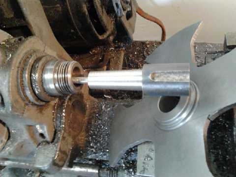
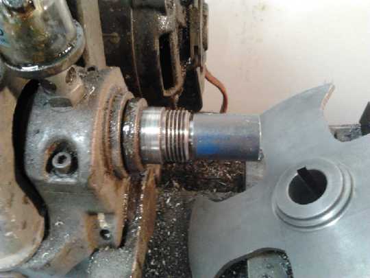
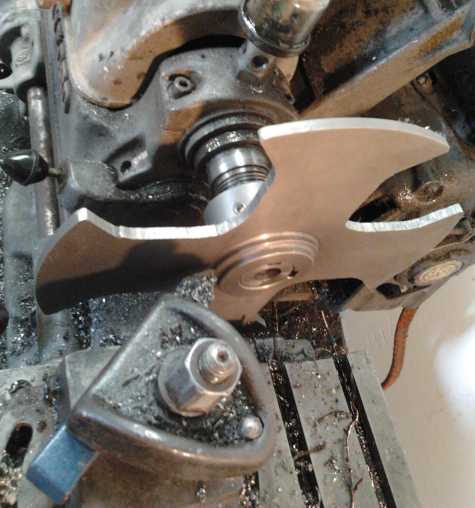 Turning AFSRM
Rotor thrust bearing flat
Turning AFSRM
Rotor thrust bearing flat
Thrust bearing on rotor
 Somewhere in
there, while I waited for the new
oscilloscope to
arrive, I made the new nickel 'negode' for the cylindrical
nickel-nickel battery. It should be a great electrode! I did a couple
of versions of a cylindrical battery by the end of the month. The first
one had a problem (bad graphite in the mix) and the second one,
finished July 1st, [also] has poor current capacity and likewise
doesn't seem to hold charge properly. What am I doing wrong?
Somewhere in
there, while I waited for the new
oscilloscope to
arrive, I made the new nickel 'negode' for the cylindrical
nickel-nickel battery. It should be a great electrode! I did a couple
of versions of a cylindrical battery by the end of the month. The first
one had a problem (bad graphite in the mix) and the second one,
finished July 1st, [also] has poor current capacity and likewise
doesn't seem to hold charge properly. What am I doing wrong?
The Mazda RX7 EV update this month consists simply of
saying that after the NiMH battery swaps in May, I drove it 9.3 miles
on
June 21st with only a bit of a charge at one point. (only because I
forgot to plug it in after the second trip.) The batteries weren't
bottomed out yet, either, and I could have gone probably about another
3 miles if I had had somewhere to go. That'd be almost 20 Km - a big
improvement over 10 to 12! And by replacing just 2 bad cells, I have 7
tubes of left over cells (70 AH @ 12 volts) to use for something that
doesn't draw as much current as the car - and to run experiments on
re-hydrating the cells, which could possibly restore their current
capacity. The lithiums are still doing great. The four remaining
lead-acids are working well and have outlasted all the others by a wide
margin. If only I knew which ones were the ones to get when I go to buy
them!
All the while, while doing all these very exciting
projects, exciting
and successful as they were, it's been gnawing away at me that I still
haven't completed my SR & ED application, and that I still don't
have my bitcoin miners, which I got in February, running. I figure
that's "costing" me hundreds of dollars a month in income I could be
getting. That just might be the money I could be leveraging into funds
to commercialize some of my products.
Much to my amazement after so long with no sales except
the long-running Electric Weel kit/project, someone ordered two of the
stackable 12V, 10 D cell 3D printed battery cases by e-mail. He paid
and I sent them. Say, isn't this the way business is supposed to work?
In Passing
(Miscellaneous topics, editorial comments & opinionated rants)
Plastic Debris Clogging Oceans - Burn your grocery bags?
Perhaps you've heard there are "islands" of plastic debris
"the size of Texas" floating in the oceans? This is becoming a critical issue to Earth's
ecology. It keeps getting worse, and no one is dealing with it. Whether
it's related to the "dead zones" isn't clear.
I met someone, a qualified ship captain, who had proposed
creating a clean-up ship operation that would profit from selling
the
recovered plastic. Of course that would require capital, and he said he
couldn't find any interest or support. (It seems to me this is another
illustration of how those who run our society have abrogated their
responsibilities in ways that seem to make no sense whatsoever except
that they must take some sort of satisfaction in doing harm - You can't
get good fruit from a corrupt tree, even when it seems to make sense by
their own "anything for profit" philosophy.)
Now, people keep saying "Don't burn plastic. It
creates toxic smoke." But there are many kinds of plastic, and this
isn't true of all of them. In particular, polyethylene such as is used
in grocery bags, soft transparent food bags, and many small plastic
containers, creates nothing but
carbon dioxide and water vapor. It burns as cleanly as gasoline or
cleaner. And a light plastic bag is probably
composed of less petroleum product than you burn to back your car into
your driveway. If you drive a gas car, but worry about burning
plastic bags, it's like worrying about an anthill and ignoring the
mountain. And if you can stick bits of paper, sawdust or whatever into
the bag
first, it's doing double duty in containing stuff that would otherwise
be messy to burn. And plastic as 'kindling' of a sort can help get a
fire going. (Even so, I often re-use my grocery bags. They're easy to
stuff into your pocket, and to keep a bunch in the back of your car.)
Likewise, polypropylene is polymerized cyclopropane, and
so has no more burning emission than propane, again just carbon dioxide
and
water - a cheery flame with very little smoke. In addition to many
small plastic containers, cloth grocery bags and landscaping fabric are
made of polypropylene.
Look for the recycling symbols identified as "PE", "LDPE",
"HDPE" (low & high density) and "PP" for these clean burning
plastics. Ideally all these can be recycled, but except for larger,
heavier pieces, the truck carrying all that fluff probably burns more
petroleum product than what it's carrying.
Thus it's my feeling that the best way to deal with them is to burn
them in a woodstove or fireplace. At least that way you can be sure
they're not adding to the mountains of floating debris in the oceans.
(Some plastics that DO make noxious smoke include: PS, ABS, PVC, PETE.)
Chem Spraying Continues
THIS is FRESH RAINWATER?
 Many if not
most days, now that I know what I'm looking at, I see chem trails and
sometimes see or hear the aircraft making them. On the 15th extra-heavy
chem trails criss-crossed the sky all day.
Many if not
most days, now that I know what I'm looking at, I see chem trails and
sometimes see or hear the aircraft making them. On the 15th extra-heavy
chem trails criss-crossed the sky all day.
They are known to prevent precipitation, and rain clouds
have passed by overhead without any rain on several occasions this
spring. (Probably the clouds finally release a deluge to cause the many
flash floods seen this year in the interior of the continent.) A local
fire
chief says it's "very abnormal" for it to be so dry this early in the
summer.
One evening there was, finally, a light sprinkling that
continued into the night, which filled a 220 liter drum from the roof
downspout 2/3 full. I moved the hose to a second drum before I
went to bed, which filled about 1/3. Since it hadn't rained in quite a
while, one might expect a little dirty water off the roof at first. But
this picture is the second drum (which has an open top). It was
foamy at first. Later it was just this dark reddish brown color. Just
what
are they dumping on us? Yuk! (Later I found some water off the
galvanized garage roof in a garbage pail, that wasn't too bad. Still...)
Is it any wonder there's huge die-offs of
sea life? A video about "extreme weather" of last winter showed masses
of dead fish floating in lakes and washed up on ocean shores as
reported on the news in various places around the world. It's been
widely said that there is "a dark cabal" (as president Kennedy warned
decades ago) manipulating from "behind the scenes" who would like the
population reduced to that of the stone ages, and to enslave the
remainder. Destroying the major food sources of the world is certainly
a way to kill people. Can that be the motivation for all this?
On about the 23rd someone told me there has been a massive
algae bloom on the west coast of Vancouver Island that makes all
previous algae blooms look like peanuts. I was told the entire fishery
was shut down. I haven't heard any more about it. If it's true and
really all that bad, logically we may next hear about another vast fish
and sea bird die-off. Even non-toxic algae blooms, in sufficient
density, cause oxygen starvation in the water as the algae dies, which
kills the fish. Lack of food, or as seen recently the chem foam itself
on the water, can kill the sea birds and other creatures. It's
unsettling to look up and and realize that half the clouds hold not
moisture but unspecified and unidentified 'nefarious' chemicals. Many
can be identified as chem trails spreading across the sky and sometimes
the planes are seen, until one becomes suspicious of all clouds.
July 3rd: Last week the newspaper said Victoria had plenty
of water in the reservoir in spite of the lack of rain and heavier
usage recently - nearly 90% full. Hurrah! Today, just a week later,
severe water restrictions are being imposed. Huh? Who makes this stuff
up? My own rain water collected mostly from 36 hours last March
collected in the "swimming pool" is almost 3/4 used up. It shows the
value of storage capacity. I suppose it won't rain again here until mid
August - if then. On July 3rd also open fires have been banned, and
it's said things are tinder dry. This part is understandable. Water
rationing with a full reservoir isn't.
Why aren't there diplomatic protests, seeing the US air
force is now chem spraying in Canadian territory? Why aren't more
people protesting? And how anyone has the gall to perpetrate such
atrocities on the planet they live on I don't understand.
Please stop.
Eating Crow
On the 16th I went out to feed the goldfish about 10:30 AM
and found a drowned crow in the 'trench' pond, apparently a young one.
Making the pond with no
shallow place to stand and a drop-off from the rim was intended to keep
predators out. It wasn't there the previous evening, so it must have
just happened that morning. (Later I found a young crow in the garden
that
couldn't seem to fly over the fence and leave. Perhaps it was its
sibling that fell in?) Notwithstanding the derisive expression "eating
crow", or maybe just because of it, I plucked and cleaned it and boiled
it (about 10 minutes - 5 was too short) for
lunch, including the heart, liver and gizzard. It was a little tough,
but good meat.
This isn't a big livestock region, and the small island
deer that today wander around town eating peoples' gardens won't last
long
when and if the food
supply chain gets cut off. People may well need to do such things to
eat, so, strange as the idea seemed at first, I thought I'd get in a
little
practice. Somebody somewhere does it with all the chickens, pigs and
cows
we eat, and I saw in a National Geographic once that the Basques in
Spain would put up big nets to catch various small birds for food. Lo
and behold, Joy of Cooking even had a section on "small game
birds". And when I was little in Edmonton I helped pluck ducks,
partridge and
pheasants that my dad used to shoot, so it wasn't totally alien
territory. (Wild game birds are delicious. But I once
had a pretty tough partridge. Beef can be tough too, and after all,
crow is just cow with an 'r' in it.)
Joy of Cooking said blackbird and crow, if eaten
of
necessity, should be "parblanched" before cooking, which involved
putting it in cold water and bringing it slowly to a boil. That's when
I
figured I might as well just boil it. The part about "if eaten of
necessity" by German authors reminds us that food shortages do
sometimes occur in tough times, and not just way back in history or in
the "third
world".
But I want to get in some practice fishing this summer, in my
electric outboard boat, also trying out the new motor and controller in
real use. Most everybody likes fish! (I trust there still are some in
the strait.)
TPP, TPA or whatever it is...
How can a law or public agreement be a secret? The terms
are "classified". No one is allowed to see them, or having seen them,
is allowed to talk about them or make copies. Any US congressperson who
tells the public what the agreement is all about will be thrown in
jail. (I thought congress made the laws!?! How could they have decided
such a thing against themselves?) Evidently the public isn't even to be
told the terms for four years after it's been implemented! The
government says "Ignorance of the law is no excuse", but we're not even
to be permitted to know what the law is? But from leaks we know that
corporations can take governments - ie, the citizenry - to court to sue
for profits they they could have made if a decision they don't like had
been in their favor. The people can never reclaim any property that has
been 'privatized'. And legal actions aren't to be contested in real
courtrooms, but in private hearings behind closed doors. We may not
know what the rules are, or what was decided or done in the name of
this "deal", but we are expected to abide by whatever we are told, or
take whatever penalty is meted out for any transgression of the rules
we haven't been told, by a secret kangaroo court hearing with no appeal.
This so-called "trade deal" effectively takes the power to
make laws out of the hands of elected lawmakers and gives it to global
corporations and banks. Is that who we want running the world?
Democracy is to be officially subservient to corporatocracy. Let the
implications of that sink in! Are these, especially the banks, not the
lampreys which have attached themselves to the unwitting shark, sucking
the economic blood of productive citizens and of society as a whole?
And now they are demanding total control and reserving all rights to
themselves? Will they not kill the society that gives them life?
Apparently the madness must continue until most every
surviving human says "Enough is enough! No more!" Then they will
reassert their God given individual sovereignty to create societies of
strong families that will have more moral sense and the courage to act
on it against threats and coercion, who will trust in humanity but
individually and together rein in all those who make outrageous demands
and perform outrageous acts trying to gain unfair advantage over
others, keeping in mind the cosmic core values (quality of life,
provision for growth, equality) in their acts and decisions.
"Someday love will rule this very world." - Jesus

I recently saw a great video on youtube titled All
Wars Are Bankers' Wars. While I don't agree with everything it
says, it gives insights as to how the insidious process of behind the
scenes control of societies, of their finances and economies, has
worked over the past several centuries. But with the internet, people
are gradually learning how these hidden things work, and soon and in
the future will no longer tolerate them. For the few most stubborn and
deluded individuals working insidiously and tirelessly behind the
scenes to enslave humanity, we have a celestial promise that they will
be "unceremoniously removed from the planet" when the time is ripe,
their remnant Luciferian philosophies no more to disturb planetary
progress.
Greece: First Domino?
The latest bank runs closing the banks in Greece are only
the tail end of around 35 billion Euros withdrawn this year, from a
total of around 160 billion Euros on deposit in Greece in January.
Since banks keep only a small fraction of the currency placed on
deposit available, European central banking has (if I have it right)
given emergency "liquidity" money to them five times to keep them
afloat. 4 billion dollars withdrawn in 5 days at the end of June has
brought things to a boil. The financial institutions don't like the new
Greek government, which outright stated the obvious: "Greece is
bankrupt.", shortly after being elected. They refuse to offer any terms
besides "Give us Greece's pensioners' money, right now.", which
wouldn't help Greece except to buy them another five months, ending
with them right where they are now. They wouldn't even grant a few days
to await a national referendum on whether the Greek people want to
accept this temporary "solution". The referendum is to be held on
Sunday July 5th and it's expected that the Greek people, in spite of
the banks being closed, all the fears, and apparently an organized
[read, paid for by the bankers] campaign to convince people to vote
"yes", will probably vote to reject this latest imposition of further
"austerity". (If they accept European terms, PM Alexis Tsipras and
finance
minister Yanis Varoufakis have said they will resign.)
The Syriza party had only a tiny fraction of the vote in
the previous election, but ran on the promise of ending European bank
imposed austerity - the cause of much very real suffering and dozens or
perhaps hundreds of protests in Athens. It's said the banks care little
for anything now beyond punishing the government unexpectedly elected
by the Greek people, and certainly they have no sympathy for the people
of Greece or Greece's plight.
Most of the immense "Greek bailout" money since 2010 went
to financial institutions in Greece. They were bailing themselves out.
The government received very little of it, yet is expected to pay the
huge debts. (Remember Thomas Jefferson said there are two ways to
conquer a nation: With armies and with debt.) The new Greek government
has
pointed out that several European nations are in little better shape
than Greece and proposed a conference for a general write-down of all
debts in Europe. The banks are apparently furious at that idea - that
someone is working against their financial
tyranny. (Will they dig out some patsy malcontent to
try to murder Tsipras and or Varoufakis? Blame it on "terrorism?" Asked
how it felt to be elected to power in Greece - and one might add, to go
from being a Texas university professor to the center of the world
stage - Varoufakis replied "Scary!") I found a good briefing video
by Varoufakis on youtube on July 2nd, explaining (in English) what was
- and wasn't - offered and why they were recommending people vote "no",
but
that that recommendation would change to "yes" if a Greek deal offering
a
ray of hope for the future was brought to the table - there were two
full days left for the bankers to make an offer.)
Missing the payment due June 30th is clearly a loan
default by Greece, and no realistic alternative or compromise has
been offered by the "Troika", the ECB, IMF and 'Eurozone Commision'.
The question now is whether this hard attitude
makes Greece knuckle under so they can steal the remaining wealth of
its citizens, or if it may somehow blow over for now, or if it may
prove to be the first domino in the collapse of the corrupt, insolvent,
unsustainable ponzy scheme that is the global financial system. If it
is the latter, events could move quickly. There are said to be 100
trillion dollars of outstanding Greek "interest rate derivatives" and
"credit default swap derivatives", which the major banks have
guaranteed.
On the other hand, economies are bad everywhere since so
many people are competing for the world's resources, and some like Greg
Hunter (USA Watchdog.com) feel the
decisions made at this point will make little difference to the final
outcome. Bix Weir (always with a different take on things!) thinks the
banks want Greece to default, and then they'll start printing the
truckloads of money Europe already needs to keep the system afloat, and
blame it on Greece.
As I said after Cypress, the next time a country uses
"bail-ins" - theft of depositors' accounts - to save their banks,
people world-wide will probably start withdrawing their accounts and
hiding their cash. It might take until "bail-in" #3, but #3 will
probably closely follow if #2 gets away with it. (...which has led to
the proposal to ban cash entirely to prevent bank runs - and to further
interfere in peoples' lives!)
---
My version of the "trickle down" theory of economics:
Wealth from the productive starts circulating through the economy, but
as it comes in range, it is sucked to the bottom into giant traps to
add to the immense fortunes of the bottom feeders, never to re-enter
circulation. Thus everyone else is sucked dry and economically
enslaved, working harder and harder stay in the same place.
New Horizons Approaches Pluto
The New Horizons space probe, after 9-1/2 years of flight,
will fly by the 2345 Km diameter sphere called Pluto, around which
orbit an even smaller 1250 Km diameter moon called Charon and several
"oids",
also titled "moons" per the prevailing misleading custom that gives
equal billing to worlds half the size of Mars and to little whirling
chunks of rock. Pluto is about 1/3 the size (by
volume) of Earth's moon. For more on the mission: http://www.nasa.gov/newhorizons
and http://pluto.jhuapl.edu .
For my take on how Pluto with its associated bodies as well as Triton
formed (think of the breakup of comet Shoemaker-Levy 9 near Jupiter): http://www.saers.com/recorder/craig/
(scroll down to find article link).
BTW, I've seen nothing definitive on Ceres. The views are
getting closer, and some ice extrusions are visible. Of course, I
should be searching for spectral findings.
Newsletters Index/Highlights: http://www.TurquoiseEnergy.com/news/index.html
Construction Manuals and information:
- Electric Hubcap Family Motors - Turquoise Motor Controllers
- Preliminary Ni-Mn, Ni-Ni Battery Making book
Products Catalog:
- Electric Hubcap 7.2 KW BLDC Pancake Motor Kit
- Electric
Caik 4.8 KW BLDC Pancake Motor Kit
- NiMH Handy Battery Sticks, 12v battery trays & Dry
Cells (cheapest NiMH
prices in Victoria BC)
- LED Light Fixtures
(Will accept BITCOIN digital currency)
...all at: http://www.TurquoiseEnergy.com/
(orders: e-mail craig@saers.com)
Daily
Log
(time accounting, mainly for CRA - SR & ED assessment purposes)
1-3: Finished May TE News (#88)
4: Added 4 magnets to rotor to make Electric Caik "Unipolar" motor into
"BLDC4" bipolar motor (so called because it has 4 rotor magnet poles
per 3 phases instead of 2 poles). Edited & Printed Electric Caik
Hall sensor PC board, and an LED flat panel light board.
5: Boards etched badly. Made a 2nd Caik board (satisfactory). Epoxied
in the PP strapping to hold the new magnets securely. Moved the 2
tilapia from the mini-fridge into a barrel and shut off the aquaponics
pump.
6:
7: Drilled PCB, soldered parts and cable on. 2 Tilapia died - aquarium
water bad. (High ammonium nitrate?) Transferred remaining large female
to a 10 gollon aquarium.
8: Installed Hall sensor PCB, Assembled motor (not without a few hicups
and adjustments)
9: Emptied and cleaned out 30 gallon aquarium.
10: Brought it back and refilled it.
11: Put the 2 tiplapia from the barrel into the aquarium. One didn't
look well and died within a few hours. The other seemed fine.
12: Put the last tilapia into the aquarium, the big female. She didn't
look well either, but was still alive the next day, with a bit more
color. Rewired the motor controller sensor wires with two 3-wire plugs
to match the motor. Then I changed both motor and controller to match
the PC board socket, ie, 123456 = Ground, +12Vsupply, SenseA, SenseB,
SenseC, Temperature.
13: Tested motor with unipolar controller. (Controller still gets hot.)
14: Ordered 'modern' oscilloscope to check waveforms in motor
controller, and a few other parts.
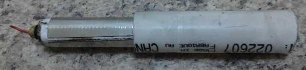
15: Made inside-fitting end caps for 3/4" PVC pipe batteries. Painted
battery negode with micro nickel flake powder in gum arabic.
16: Oscilloscope arrived. Learning how to use it... OSC signal on motor
controller not right.
17: Motor controller testing and troubleshooting. Got it running well!
(but not perfectly)
18: More motor controller testing and troubleshooting.
19: More motor controller testing and troubleshooting. (Main problem:
high pulse current
was overdriving apparently inadequate 'flyback' diodes!)
20: Redoing motor controller schematic & PCB layout in Eagle PCB.
21: Made morse taper shaft for mounting rotors on lathe; turned AFSRM
rotor to hold thrust bearing.
22:
23:
24: Made new bar & mounted heavier 'flyback' diodes. (They are
STILL inadequate, but not quite as badly.)
25: Consult with AGO about wobbling motor shaft. (Got new piece of
shaft owing to slightly tapered end on old one.) Made NiNi battery
'posode' & assembled battery (wrong mix - contained art store
graphite! Self discharge.)
26:
27: Talking with prospective partners.
28: (Played a concert with a concert band, on my own invented
instrument, the Supercorder - playing flute and oboe parts.)
29: A few more motor controller tests, with diodes, and a writeup about
that for the OSMC motor controller e-mail group.
30: Made 2nd nickel manganate battery posode.
July 1: motor test: bypass coil. Sure enough, watts to run motor goes
WAY up. More converse with OSMC: someone told me about "FERD" diodes,
which may have lower Vf for the recirc diodes (if I use enough of them
in parallel).
Electric Hubcap Motor Systems - Electric Transport
"BLDC4:3"
Electric Caik Motor and Unipolar Controller
Having decided the unipolar BLDC motor wasn't the way to
go seemed
to leave me with options of:
a) buying BLDC motor controllers to go with my motors.
b) trying to improve my controllers so they wouldn't blow up at high
currents, so they'd be a product along with the motors.
c) making axial flux switched reluctance motors (AF-SRM.s) that would
use an inherently more reliable type of controller.
Option B wouldn't give me anything better than anybody
else has and I'd probably have to charge more. In option C was the
possibility of making regular SRM controllers or, if I could make it
work well, my new type with half as many power transistors and half as
many diodes, the
remainder being replaced by a coil (to allow return energy from the
motor
coils).
d) Then along came the Electric Weel generator, needing a motor
controller... but it had been made with 4 magnet poles per three phases
instead of 2, and (I thought) a regular BLDC motor controller won't
work with that.
But it sometime dawned on me that the more reliable "unipolar" or "SRM"
controller that I designed and made last winter would work instead, and
better still, that it looked like it
would be superior to today's standard BLDC configuration. With 4 rotor
magnet poles going by where there were two, the electrical frequency is
doubled and each coil is ON right between a north and a south magnet,
where the motive force is highest attracting one and repelling the
other. The torque per amp should be high and the torque ripple lower
than a SRM.
To me, given my many motor controller failures and seeing
so many elsewhere as well, the reliability of the motor controller is
the most
important aspect. Of course I would do my best work, but even if it was
"cheap" and "glitchy" the controller wouldn't suddenly fry at high
currents, so here was my best chance to make highly reliable
controllers in-house to go along with the motors.
 On the morning of the 4th I prepped the existing unipolar
rotor by scraping off the paint and epoxy where four more, opposite
polarity magnets were to go. Milling four more slots would have been
awkward and
left countless filings stuck to the existing magnets. So instead, I
decided to slit the straps and fit each half through the existing four
magnet slots, which were fat enough to pass another strap through once
excess epoxy and strapping were cut or filed away. Not ideal but
hopefully good
enough for at least 3000 RPM without magnets working loose and flying
off.
On the morning of the 4th I prepped the existing unipolar
rotor by scraping off the paint and epoxy where four more, opposite
polarity magnets were to go. Milling four more slots would have been
awkward and
left countless filings stuck to the existing magnets. So instead, I
decided to slit the straps and fit each half through the existing four
magnet slots, which were fat enough to pass another strap through once
excess epoxy and strapping were cut or filed away. Not ideal but
hopefully good
enough for at least 3000 RPM without magnets working loose and flying
off.
Although the magnet placement jig couldn't fit around the
magnet strapping, I bolted it over top and used it as a visual guide
for placing the new magnets to what I hope is within a couple of hair
breadths of
where they should be. I was afraid it would be hard to get the 2" x 1"
x 3/8" magnets to stay in place without the jig, and not jump over
and glom onto the other magnets, but they stuck down to the rotor steel
well enough to prevent that, even with wet epoxy under them.
I forgot to sand the slick epoxy coating on the new
magnets. This is where the original Electric Caik had failed on its
first run, the magnets simply sliding right out of their (admittedly
bottomless) pockets at no great RPM. But these didn't jump off when
hammered... but then the epoxy wasn't fully set yet. I decided to wait
and
see how they fared once it was. (Then I forgot all about it. I've run
it up to 1200 RPM so far with no trouble.)
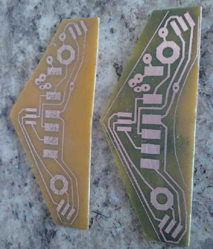
The next step was to make a regular hall sensor circuit
board as used in the other Electric Caik motor, because the optical
sensors were crowded enough to bother me. So if I didn't need them for
this motor, I'd change it. I started that on the 4th too, and etched it
(along with another LED light board) on the morning of the 5th. I
thought I finally had the toner transfer method circuit board making
down pat. But these boards seemed to take ages to etch. After well over
an hour, I thought it must be really weak etchant. I looked again, and
suddenly wondered if the unusual yellow board material looked the same
as the
copper in the yellowy ferric chloride. I pulled one out and rinsed it,
and found it was not only done but badly overetched, with the traces
being
undercut and thinned. There were some breaks in the runs.
I didn't quite have to start over since I'd printed two
copies of the sensor board, but it was afternoon before I had a board,
with just 15 minutes of etching in the same etchant. (Again it didn't look
done until the etchant was rinsed off, but I was wise to it this time!)
While waiting for the first "slow" etching, I managed to
work the PP strapping for the new magnets through the slots, after
widening them by filing with very thin files to get some of the old
epoxy (and maybe some of the PP) out. In the afternoon I epoxied the
straps on. It looked a little messy, but I trust it'll be good for 3000
RPM or so once it's balanced. I didn't bother with balancing for now.
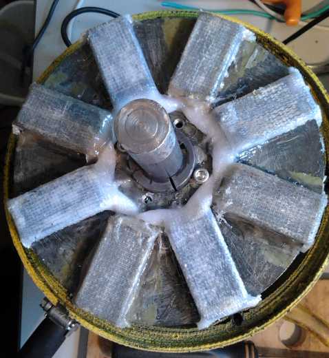
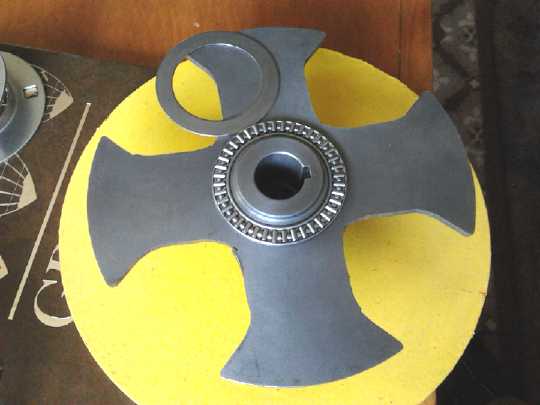
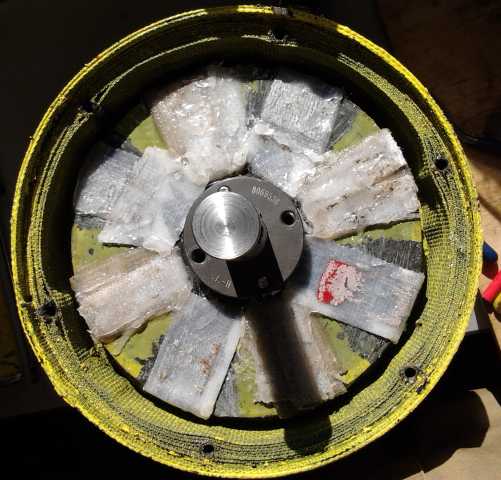 Motor open,
showing Magnet Rotor from the back
Motor open,
showing Magnet Rotor from the back
 On the 7th I
drilled holes in the magnet sensor PCB and
put the
components on. I had a lot of trouble with mirror images because
this board has the copper on the top instead of the bottom, so whatever
I thought was right was wrong.
On the 7th I
drilled holes in the magnet sensor PCB and
put the
components on. I had a lot of trouble with mirror images because
this board has the copper on the top instead of the bottom, so whatever
I thought was right was wrong.
On the 8th I turned the (oops, mirror image) hall sensors
over and then
soldered the cable to the board. The fact that 6 connections are needed
is annoying for using "trailer lights" connectors, but I can't think of
any other connectors I'd rather use. Instead of using a 5 pin "trailer
lights"
connector as I had been doing, and then needing one more pin for the
temperature sensor, I
used two 3-pin connectors as follows, with "F" and "M" applying to the
controller side, the motor being opposite. (There is a 6-pin "trailer
lights" connector, but it's two rows of 3 pins and rare - special
order. And they might be hard to plug in and unplug.) I
didn't use two identical plugs because they would be bound to get
connected to the wrong wires, so I did one the other way around. I
pinned it one way, then later I realized it would be confusing that it
wasn't the same as the motor controller's header pin pinout, and I
changed it
to match: 1--6 = ground,+12V,SenseA,B,C,Temperature.
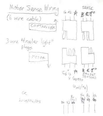 The first plug has one male
pin on the controller side...
The first plug has one male
pin on the controller side...
1. M Ground
2. F Power - +12 Volts
3. F Magnet Sense A
(The motor side is of course opposite: FMM)
The second plug has the two male pins on the controller side...
1. (4.) M Magnet Sense B
2. (5.) M Magnet Sense C
3. (6.) F Temperature (AD590, 10mV/°K)
(The motor side is FFM)
(Now I just hope people don't get these confused with identical 3-pin
plugs for speed control and a forward-off-reverse switch when they're
installing a system. Anyway, it reduces the variety of the inventory!)
Then I assembled the motor with various trials and
tribulations. (It sure could have used another 1/4" of height... and
1/8"
greater radius... for clearance in the rotor compartment!)
Piles of Testing, Troubleshooting and Correcting - New Oscilloscope
I tested the sensors board with the lab power supply,
a prototyping board (for connections and pull-up resistors), and a
voltmeter,
turning the motor to see the signals change with the rotor magnets. I
was out of hall sensors and I used one labelled "?" for the third one.
It didn't work. Neither did the temperature sensor. Had I got it mirror
image after all that?
Then I thought to use a hall sensor from a left over
circuit board. I rooted through the drawer and there were some. I
disassembled the motor stator compartment to access the board. The
temperature sensor
was squashed under a coil. That was fixed by straightening it. When it
was all back together it all worked.
Next was to hook up the 'unipolar' motor controller and
try running it. Since it ran (barely) as a unipolar motor with only
N-N-N-N- magnets on March first, I anticipated no problems at least
getting it to turn
with NSNSNSNS magnets. The question was how much energy would go into
heating the transistors in the controller instead of turning the motor.
For this, I had the other coil, with twice the inductance
(400µH), to put
in series with the power. The trick should be that the series coil
should have
much higher impedance to the coil turn-off spikes than the motor coils
(90µH), so
that the return energy would all be back to the supply by the time the
" B+' " coil voltage started to rise much.
It seemed to me it shouldn't matter what frequency the
PWM/CRM was at since the reverse spike comes after the pulse turns off,
regardless of how long it was. But that's probably not exactly true.
The longer the pulse is on, the more energy may be in the coil.
I got tied up with various things, and it was the 12th
before I got the sensor cable wired. I ran the motor on the morning of
the
13th. (@17 volts) I connected the coil phases per TE News #85 - I
*thought* the magnet sensors were the same way around as back then, and
it proved to
be right. It seemed a little stronger with double the magnets, but
still pretty feeble, and the driver transistors still got hot fast with
just a few amps of drive. Just when I thought to try it backwards and
see if it ran the same that way too (to verify that the phases were
connected right), a transistor burned out.
The energy return coil idea didn't look good so far! Then
I checked over my wiring. The energy return 'flyback' diodes, on a
copper bar hidden underneath the controller PC board, hadn't been
connected to the common supply side! Well, that would explain a lot!
(In fact, that may have been the problem last winter, too, seeing the
symptoms were the same.)
In the afternoon I replaced the blown mosfet (phase C),
connected the diodes, and tried again at 18 volts - the voltage that
had caused a quick blowout in March. The transistors still got hot
pretty fast, but this time I could turn the motor up a little higher,
and didn't get an immediate blowout. Phase C seemed to get hotter than
the other two. The flyback diodes got a little warm. It was
still only 5 amps and not much power, but more than "barely turning". I
turned the current limiting up a little higher to about 7 amps and the
voltage to 20, and it was still okay and the motor turned faster. But I
wouldn't give the hot transistors a ghost of a chance of surviving 2
seconds at 200 amps!
The coil had only about twice the inductance of the first
one. Maybe it needed a still much larger coil to keep the energy from
going back into the transistors? I didn't have any bigger ones, but I
had more the same... would putting two inductors in series improve
things?
But when I thought about that... even if the energy was
being shorted, it should short through the diodes across the coils, not
through the transistors. So why were the transistors heating up? Ah...
maybe the power supply needed more capacitors to absorb the flyback
voltage? If the voltage was going above the transistors' zenor point,
they would absorb the excess energy themselves and heat up. I thought
it had two 4700µF capacitors, but on inspection they were were
270µF... at 100V rating because of the high currents and hence in
rather large cans. Probably
not enough. I added two more for a total of 1080µF. The
transistors still got hot pretty quickly, and again phase C faster than
the other two. Well, on the other side of that coil was the motor
supply, with only 640µF. I soldered another capacitor on the
bottom side of the circuit board, making it 860µF. That didn't
seem to help either.
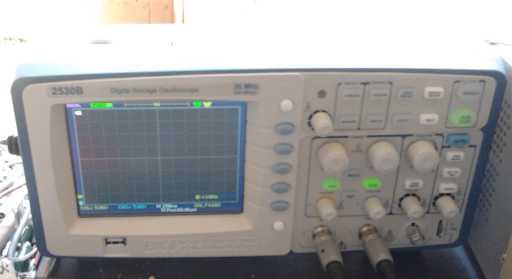 Time to get
out the oscilloscope and look at the
waveforms. ...Or maybe buy a new oscilloscope that would be reliable,
correctly calibrated, nicer, better, and easier to use than the old
10MHz, 1970.s Heathkit? I opted
for the latter and ordered a BK2530B digital LCD storage oscilloscope
the next day.
I also ordered 50
more A1203LUA hall/magnet sensors, and while I was at it, a few 555
timers and LM339 quad voltage comparators. (After chancing to see the
US$ prices before I saw the CAD$ prices at Digikey, I thought the
exchange rate seemed off. I looked elsewhere and ordered them from
Mouser instead, for about 650$ instead of 750$. The chips were cheap,
but I could probably have done much better on the hall sensors if I'd
ordered them from China. Evidently sometimes it still pays to shop
around!)
Time to get
out the oscilloscope and look at the
waveforms. ...Or maybe buy a new oscilloscope that would be reliable,
correctly calibrated, nicer, better, and easier to use than the old
10MHz, 1970.s Heathkit? I opted
for the latter and ordered a BK2530B digital LCD storage oscilloscope
the next day.
I also ordered 50
more A1203LUA hall/magnet sensors, and while I was at it, a few 555
timers and LM339 quad voltage comparators. (After chancing to see the
US$ prices before I saw the CAD$ prices at Digikey, I thought the
exchange rate seemed off. I looked elsewhere and ordered them from
Mouser instead, for about 650$ instead of 750$. The chips were cheap,
but I could probably have done much better on the hall sensors if I'd
ordered them from China. Evidently sometimes it still pays to shop
around!)
It arrived on Tuesday the 16th. Aside from the typical
functions of old types of storage scopes, it has some great features
including storage, "playback", printing on-screen the volts/division,
time/division,
offset voltage and trigger frequency, and saving the screen to a
USB memory
stick. The
range controls are optical(?) dials instead of rotary switches with a
zillion
contacts to get dirty and wear out, and there were several menus to set
things up with a minimum number of pushbuttons, which matched the menu
placements beside the display. And with no CRT tube, it's compact
and lightweight: 6" high x 12" wide x 4.5" deep. Even the probes are
easier to use, and clip onto wires better than the old ones.
After taking a while to look at the manual and familiarize
myself with the controls, I put the probe on the OSC signal on the
motor controller chip. It was wrong - staying high instead of
oscillating. Amazing how a very foggy picture of what's assumed to be
happening starts to clear up with proper test equipment! The old scope
could have told me this too, but as testing went on, the new storage
scope quickly proved its worth, showing things clearly by getting a
snapshot at the critical time, for later viewing including
expanding very short period pulses across the whole display in
sub-microsecond intervals.
I could have cleared the picture by looking more closely
at my schematic, too. I had somehow reversed the connections between
OSC and ERRAMP pins. No wonder I've been having problems. OTOH I found
had already corrected part of it last February. And I saw a better way
to rapidly end the modulation cycle if it shuts off on overcurrent.
But the next day (17th) I decided for testing to reduce
the number of variables by eliminating the overcurrent variable
modulation completely, and going with simple fixed high frequency PWM.
This all started messing up the circuit board, with
components upended and vias that had to be cut, all rerouted by messy
wires. It starts to get pointless to go into all the details. I'll want
a new PC board for the "real" controller.
There seemed to be a lot of very glitchy signals, with an
annoying thread of 3MHz oscillations at an amplitude of up to several
volts.
Even the magnet sense inputs had it, to the point where the scope
couldn't trigger properly off them. (indicating I should be using
shielded cable, and filtering them on the board!) I was amazed it
worked. But when I looked again later (after having added some
capacitors) it seemed not bad. It depended on where I connected the
probe's ground clip.
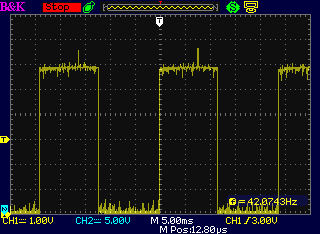 A Hall Sensor Signal - the second time with
the ground clip near the signal.
42Hz * 15 = 630 RPM
At the current sense
input, the signal was supposed to
be filtered with an RC filter (330Ω, .01µF), which seemed to do
nothing - it had the same RF noise at the same amplitude as the direct
connection. In case it needed a larger capacitor, or in case there was
a bad through-hole connection on the capacitor, I soldered on a
.1µF on the back of the board.
When I did that, the motor magically ran properly and
smoothly with the control, and the transistors didn't get hot: it was
working! Instead,
the flyback diodes got warm. Roughly, the motor seemed to use about 150
watts to idle at 1000 RPM. This didn't compare favorably to the
original Electric Caik measured at 101 watts. (TENews #60) I thought it
might
indicate inefficient energy return - especially with the diodes heating
up. However, if there was no energy return, currents could be
expected to be at least 5 times higher than the other motor, if not 10
or more. So the basic system was essentially working. (In fact, later
some of the load was shown to be the bearings, which were stuffed full
of thick grease, and the shaft, which wasn't square to the lower
bearing.)
I thought that was good accomplishment for one day and it
was 4:30PM, but a while later I remembered, then went back and dug out,
the device I made a few months ago for measuring static "locked rotor"
torque with a scale. Of course the rotor wanted to cog to certain
positions. From the center of where it naturally sat, I got the
approximate readings below. I could only get it up to about 3 amps if
it wasn't turning, partly no doubt because of the disabled current
modulation leaving only PWM, which I had set at 12KHz.
0Amps: 0g
2.0A: 140g
3A: 190g
If I set it to a rotation where it had the maximum forward turning
force with no power applied,
0A: 115g
2.0A: 230g
3A: 280g
The scale arm is 6" long, so divide by 2 for feet. 454 grams in a
pound, so
divide by 454 to get pounds. The highest relative reading was the
first, 70g/A (below), and the lowest ones, after subtracting the
cogging force, were just over 55g/A. (In review it was probably a
little lower than 140g, maybe 130-135, but the readings weren't at all
steady.)
140g * .5ft / 454 g/pd / 2A = .077 foot-pounds/Amp
As current is raised, the cogging force should become a
smaller and smaller component, since it doesn't increase, which would
seem to indicate torque ripple will prove to be relatively low. But
until I can drive it to some higher static amps, which should attain to
greater accuracy and precision of measurement, these figures seem to
indicate somewhere around .6 to .7 of a foot pound per 10 amps, as
opposed to the original Electric Caik which seemed - as measured very
vaguely since I didn't then have a good system - to be around 1
foot-pound/10Amps. This reduction seemed in keeping with the 50%
extra no-load watts.
To end the day I ran it up to 1200 RPM with about 8 amps,
in both directions. That was about all the lab power supply wanted to
put out. The diodes rapidly got hot but the transistors stayed cool.
Then 600 RPM in both directions took only about 2.75 amps, and the
diodes heated slowly. Apparently it's wasting more power to run it
higher power and speed. 'Why?'
Anyway it finally was running well, and a lot of things could be tried
or adjusted.
The next morning I turned up the PWM frequency to 22KHz. I
thought that would raise the 'locked rotor' amps and torque, but it
didn't seem to change anything. The diodes still got hot. As I began to
investigate with the scope many unexpected things were seen. On one end
of a wire things weren't always the same as at the other end. (I
probably wouldn't have noticed with the old scope.)
The gate drive signals, short tho the traces were, instead
of sitting peacefully at ground, had big glitches up to 4 or even 7
volts when a different coil was being turned on or off. These are just
the thing that blows up a typical BLDC motor controller, causing
"shoot-through" currents from the supply to ground. All they do here is
start to activate the wrong coil. That doesn't of course mean they
shouldn't be cleaned up - only that the controller is still working,
which
makes figuring out the problem much simpler.
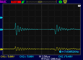 An "off" gate drive as another phase is being
switched ON then OFF.
An "off" gate drive as another phase is being
switched ON then OFF.
Both traces center on 0 volts. The lower trace is straight at the
controller chip,
the upper one is at at the mosfet gates, past the gate resistor.
The scope screen shows the problem: At 5 volts per
division (when about 8 volts turns most mosfets fully ON) these are
serious spikes, and could well be the cause of the extra power that
seems to be needed to run the motor. Why are they there, and why are
they worse at the gates than at the driver chip?
But checking the mosfet common showed almost the same
waveform, so it wasn't really turning the gates on. This gets even more
perplexing, because if mosfet common goes
above the 100mV reference on the driver chip, it should shut off the
cycle. How can it be going up several volts? But wait... what about
that .1µF capacitor I put on the current sense pin, replacing the
.01µF, and which made the controller start to work? I put the
probes on the current sense and reference pins, but the simple presence
of the scope probe on the reference pin caused the controller to
malfunction.
The next morning I increased the flux gap in the motor
itself, and the current to idle at 1000 RPM dropped to about 4.75 amps,
or 118 watts at 25 volts. Now it didn't seem so different from the
first motor. Perhaps the controller was just fine... but then why were
the diodes heating up? I also added a 270µF capacitor from the
mosfet sources to the supply to try to dampen down transients on the
current sense line and the gate drives. This seemed to be somewhat
successful.
To digress from the sequence but complete a topic, the
motor
wobbled at higher RPM.s. I thought the rotor wasn't on quite straight.
A few days later (21st) I took the top off the motor to fix it. The
lower bearing still held the shaft on solidly. So I ran it up to 1000
RPM with the top off and only the one bearing. Instead of drawing 4.75
amps it drew only about 3.5, or 87 watts instead of 118. In other
words, substantial power was being used to overcome friction. The whole
shaft wobbled, so it
wasn't the rotor, and this (more than the thick grease coning out the
gills of the bearings) was probably the major friction cause. This was
doubtless the case in the previous motor
too, and I noted in TE News #60 that it seemed to take less current and
power as the motor warmed up - and perhaps as it expelled some of the
excessive grease, or the set screws relaxed a bit. (I could see in both
cases it wasn't getting the 95%
range of peak efficiency of the larger Electric Hubcap motors, where I
used lightly greased trailer wheel bearings that didn't care if the
shafts weren't 'perfect' and IIRC was using around
70 watts for 1000 RPM. And I did attribute it to the bearings, which I
discounted as being a problem because they'll 'wear in' and improve.
But running with one bearing showed the effect starkly. I got a new
shaft to try and turn more exactly, but that's another job to get
around to.)
Diode Issues
If you want to shorten your reading, skip this down to
"Diode Report" below, where I summarized the findings.
Next I checked on a coil (at the anode of one diode) and
the supply power (at the cathode of all three diodes) and found that
for the first 1/2 a microsecond, the forward voltage across the diodes
was about 5 volts instead of .5 volts, even at the low currents I was
using. (I might never have figured this out with the old oscilloscope!)
They were power schottky diodes, but apparently they weren't the least
bit fast diodes. The amps being conducted as each diode switches on,
with the high voltage 10000 times per second would probably heat the
diodes up and cause extra watts to be needed to turn the motor - the
observed symptoms. It seems it needs fast switching diodes
(short Trr) that can also handle very high current.
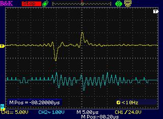
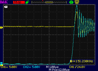 The coil voltage (cyan) as it switches off
exceeds the power supply voltage (yellow) by as much as 5 volts.
The coil voltage (cyan) as it switches off
exceeds the power supply voltage (yellow) by as much as 5 volts.
The two probes are directly on the anode and cathode of one of the 40
amp schottky rectifiers, which should clamp it at ~.5 volts.
Conclusion: fast reverse recovery time diodes are needed.
 Yellow: ON-OFF switching spikes on the
power buss,
Yellow: ON-OFF switching spikes on the
power buss,
TOP: supply side of the coil (almost 10 volts peak)
BOTTOM: at the supply filter capacitors (about 5 volts).
These are the two ends of the same 9" piece of fairly heavy wire:
with higher frequencies and currents wires aren't just wires!
Cyan: the motor side of the supply bus coil, damped by multiple
capacitors. (under a volt)
In the previous controllers, the diodes were the built-in
body diodes of the power mosfets. Here the configuration is wrong for
that, and I used the heaviest diodes I had, dual 20 amp schottky
rectifier diodes. I checked and compared the specs:
IRFP3206 MOSFET body diodes: Trr = 33nSec (typ), Vf = 1.3v (max, @75A)
If(max) = 200A, Ifm(max) = 840A
TRPS40M120 dual schottky rectifier diodes: Trr = not specified!,
Vf
=
.79
(@20A), If(max) = 2 * 20A), Ifm(max) = 2 * 220A
The datasheet claims that the diodes are good for "high
frequency switching power supplies", but doesn't even specify Trr!?!?
But the reverse capacitance graph up to (2 * ~.001µF) seems very
high to my uneducated eye, so it looks like it's an awfully slow
recovering diode. Not what's needed for capturing the energy from a
short pulse!
I didn't think much of the 1.3 Vf for the MOSFET body
diodes, either. That seemed like a notable energy waste and heat
source, that I was unaware of until now. (What happened to "typical" .5
Vf for schottkys?) I thought they might work better for now than the
schottkys until I figured out what to order. Then I went to Digikey.com
and found that simple diodes with the specs I wanted were in fact far
more costly than the IRFP3206 with the built in body diodes - they
started at over twice the price and went up from there! And the only
spec that was better for most of them was Vf, mostly about .95 to 1.1
volt. But that was "typical" and the 1.3v was "maximum", so they
probably weren't much different. The body diodes in the mosfets I
already have are superior in every other way. Anything with faster Trr
than 500nS was considered "fast". Only one was faster than the mosfet's
diode.
Then I checked the body diode specs for the other power
mosfets I have, IRFS7437.s, and they looked even better, and cheaper.
Again Vf(max) was 1.3 volts, but Vf(typ) was 1.0 volts. 1000 amps
momentary pulse. 30nS Trr. The one minus was that they were only 40
volts reverse voltage. That's okay for the 24 volt controllers. I'll
have to find something else for 36 or more volts. I started this motor
controller thinking to cut the number of mosfets in half from 12 to 6,
but now it looks like I'm going to add three just to use them as
diodes! (But other than tying the gate to the source so they never turn
on as mosfets, what's the difference? Lots of the diodes are in the
same or similar package styles.)
On the 24th I changed the flyback diodes to IRFP3206
mosfets (gate shorted to source). On the scope they still appeared to
be rising substantially above the supply voltage, but not as much,
maybe 3 or 4 volts instead of 5, and for a shorter time like 300nSec
instead of 500. The current to idle at 1000 RPM, with the motor still
open (unchanged), dropped again to about 3.25 amps from 3.5; 81 watts
instead of 87. The transistors stayed cool. The diodes still got hot -
probably not as fast. Wow, how much of the heat in a regular controller
is from the flyback diode action of the mosfets, rather than from the
actual mosfet conduction of power?
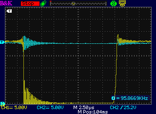
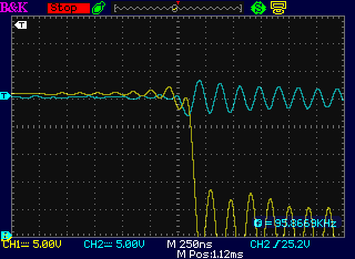
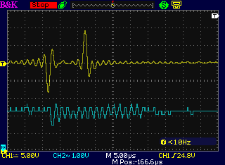
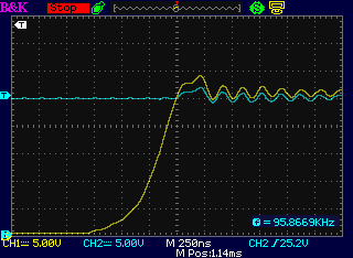 Coil pulses with single IRFP3206 'diodes'
Yellow: the coil. Cyan: power line.
1: An entire coil ON pulse - a little under 20µSec.
2: Turn-on, 250nSec/div
3: Turn-off, 250nSec/div (Energy recirculation when coil > .8 volts
above supply voltage.)
This means a design change: the diodes will have to be
firmly heatsinked to the case. (But electrically insulated.) If they
get hot on a copper bar with 3 amps of motor current, the whole case
will get hot with 200 amps. And that's with 1/2 as many diodes as a
regular controller.
A possibility to eliminate much of the heat is to have
"active rectification", where mosfets turn on whenever the diode would
be on. The forward drop of a mosfet when fully on is much lower
than a diode, so its power dissipation is also lower. But it gets
complicated.
Silly as it seems, it should be useful to parallel two or
more diodes so they handle the spike of current, short as it is,
without such high forward drops. If two diodes lowered the drop to 2
volts instead of 4 volts, they would not only split the heat, there
would be half as much of it. I made the copper bar for this on the 28th
and ran tests then and the next day.
Torque Inconstant
I checked static torque per amp by turning the supply to
1,2,3 and 4 amps with the torque measurement arm attached. Kt (torque
per amp constant) is supposed to be linear, but (come to think of it),
that's the "AC" current, presumably as measured on any phase, not the
average DC
current from the supply.
1A: 100g
2A: 150g
3A: 180g
4A: 215g
Perhaps the thing to do would be to apply a DC current
straight to a coil from the lab power supply and leave the motor
controller right out of it.
Diode Lab Report
I found the diode stuff important enough that I explored
it fairly thoroughly. On the 29th I wrote a "lab report" on it and sent
it to OSMC@yahoogroups.com [Open Source Motor Controller], where I had
been conversing with knowledgeable people about the new motor and
controller. I noted the surprising amount of heat - energy losses - in
the diodes. Of course, the "half wave" controller has only one set of
forward diode drop losses instead of two, so that source of heat and
energy loss is actually halved.
Here is a copy of the report, where I summarized the main
points/findings.
For those interested...
I said I'd have more on the 'flyback' diodes that take the pulse of
energy stored in the motor coils and feed it back to the power supply.
So here's my "lab report". The whole issue seems more noteworthy than I
had expected.
In this sort of controller, often used for SR motors, the diodes are in
the wrong place to be the body diodes of the mosfets. That lets us view
the diode activity separately from the mosfet switching aspects.
In this particular "single ended", "half wave" or "unipolar" motor
controller, with no high side mosfets and only one direction of motor
coil activation, the complication is that the spike is up above the
supply voltage, but the other side of the coil is connected to that
same supply (instead of to high side mosfets) and not referenced to
ground in any way except when a coil is turned on. So a 'flyback' diode
to "+" would simply short out the motor coil, wasting the energy.
Rather than doubling the components by adding high side mosfets and low
side diodes as is typically done, I put in the supply line coil, to
dynamically decouple the motor coils from the battery for an instant
while the turn-off pulse dumps back the dynamically stored energy, into
capacitors or the battery.
The system seems to work. The supply current is much lower with the
diodes than without and the driving mosfets stay cold (at the lower
currents for an unloaded motor). But, unexpectedly to me, the diodes
heated up badly.
---
Being used to seeing and hearing ".6 or .7 volts" for diodes, I was
surprised to see forward drop ratings for really high current diodes to
be on the order of 1.0 to 1.3 volts. I was even more surprised to see
on the scope 5 volts across the ones in the motor controller.
Evidently the forward drop can be much higher in a short, high current
pulse. With 40A rated schottky diodes I was seeing 5 volts for 500nSec,
and they got hot pretty fast.
So I changed them for IRFP3206 mosfets, connected backwards and with
gate connected to source, just to use their body diodes as diodes.
(Rated at 200A, 840A pulse, Vf max 1.3V @ 75A) This brought it down to
around 3.5 volts for 300nSec, and they still got hot, but more slowly.
The no-load power to run the motor at 1000 RPM dropped from ~87 watts
to ~81, suggesting the reduced heat was less wasted watts.
Yesterday I doubled them, two parallel diodes per phase. This brought
it down to about 2 volts for 300nSec, and they heated more slowly
still, partly because of lower internal dissipation and partly because
the copper bar mounting was twice as long with twice as many diodes.
Current seemed to drop a little more to around 73 watts. (around 2.9A @
25V... I have to say say "around" because the analog current meter on
my power supply is something like 10% off, so when I see "2.6" onthe
needle I have to add ~.3. I did however get a new BK2530 digital
storage oscilloscope for this project. I don't think I'd have got it
all figured out with my old 1970s Heathkit scope with just one decent
probe!)
I'm satisfied with this, at least for now. (I suppose I could triple
the diodes and lower the losses a bit more.)
They surely need to be heatsinked to the outer case. (but electrically
insulated.) After it's in a case and not spread out on the bench.
---
I doubled the PWM frequency from 10.5KHz to 21KHz. The switch-off
waveform looked identical to the 10.5KHz, but since it was switching
twice as fast, the diodes got warm faster, and the power to maintain
1000 RPM went up a few watts. But there's more torque/current at 0 RPM
-
6A instead of 4A. This shows there are a few savings to be made with
variable frequency or "CRM" modulation, where the switching speed drops
with increasing RPM and or reduced load.
---
Throughout, the actual coil switching mosfets have remained virtually
cold. So the only significant heat in the controller is from the pulse
diodes.
---
BTW for the astute... the reason the power is still relatively high to
idle the 4.8KW(?) motor at 1000 RPM is that its needle bearings are
stuffed with pretty thick grease (you can feel the resistance when
turning them by hand), and the shaft isn't held straight, so it
wobbles. I have a new shaft to turn, but that's another job to get
around to. The grease will eventually thin out.
Regards,
Craig
The conversation continued with feedback on this message.
I got a couple of insights from it, and someone mentioned "FERD" -
"field effect rectifier diodes"
with low forward drop, which I had never heard of. This sort of
unexpected information is why it
often pays to run things by others. To demonstrate that the circuit
works (there was a "skeptic"), I bypassed the coil. And sure enough,
the current and power to run the motor went way up. I'll
order some FERD.s and try them out, but as the highest rated are only
so high,
I'll still have to parallel some. Maybe even 3 or 4 pairs per phase.
Any
more than that I'll stick with the IRFP3206es. Rather than rewrite
about the same topics, here's the message I sent.
Thanks everybody for the feedback!
The circuit does work. The watts to turn the motor drop with lower Vf
through bigger/more diodes. If the diodes were merely shorting the
motor coil spikes and not returning the energy, the watts would remain
constant.
But to see it better I've just tried bypassing the coil. I turned the
PWM up to 21KHz instead of 10.5, but I could still only get the motor
up to about 650 RPM, where it was drawing ~5.4 amps; 135W. (@25V)
That's where the PWM is limiting on overcurrent with the present sense
resistor. And the diodes get hot faster. (The driver mosfets still run
cold.) With the in-line coil, the same RPM takes about 1.5A; 38W.
I already know that if you try to run it without the diodes even at the
lowest power, the mosfets get hot fast, until one shorts out - also the
motor barely turns.
---
>I think using diodes to steer energy will
always be a lossy method.
At least with this controller there's only one diode drop instead of
two! And the coil voltage is drained to zero instead of just to the
power supply voltage.
>If you want to switch currents from here to
there it seems like you should use a switching device not a blocking
device.
I'm trying to keep it simple. This would re-introduce potential for
shoot-through currents, and require floating high-side gate drives,
both of which I wanted to get away from. Of course I never suspected
such high diode losses. But the FERD diodes Chris P. mentions might be
just as good, which is exciting.
>With large diodes you will always have a
significant turn-on time (and turn off). That is why you see the
large forward voltage. I would wager that you are seeing an
average voltage. With a high spike until the device turns on then
the voltage will drop to the normal forward voltage.
I think slow turn-on is probably why the pulse was 500 nSec with the
Schottky diodes I started with, and then it became 300 nSec with the
fast (35nSec?) IRFP3206.s.
Oscilloscope screen pics (in next Turquoise Energy News #89 in a few
days) show the switch-off waveforms seen, at 250 or 500 nSec/div.
---
>So some simple math. If the forward voltage
is 0.7 at 10A and you are PWM 40A the current the diode has to handle
is the same as that forward current. So lets say the recirculation
current is 40A 40*.7 is ... 28W? lets say each set of diodes is
handling that at ~50% of the time. so a total of 42W is being disapated
in those diodes.
The math looks good, but it looks like the diodes are recirculating at
several hundred amps for 300 nSec each PWM turn-off, for the presently
active coil out of 3 coils. At 21000 Hz it seems to work out to just
2.1 mSec ON out of each second. The power dissipation will average out
somewhere, but the Vf is much higher than .7V owing to the high
current, leading to excess dissipation compared to reasonable current
over a reasonable time period.
Looking at the graph of typical forward voltage versus current in the
IRFP3206 datasheet (instead of just the printed number of "1.3V max
@75A"), the current for these very brief periods seems to be in the
upper hundreds of amps, if not over 1000, considering I had to double
them up to get Vf down to 2 volts.
One could wish the coil spikes were a lower current, spread over a
microsecond or two, instead of 300nS.
---
>If you do have a lust for diodes the ST Micro
FERD diodes seem about the best. I built a 3 phase rectifier with
them for a high efficiency generator project.
Thanks Chris! These look very interesting, and I had never heard of
them! It looks like the highest current rated is the dual 60 amps at 45
volts (FERD60U45CT). I'll probably try those out for a 24 volt
controller. The fact that the graphs only go to 60 amps per and look
like the Vf voltage goes higher rapidly above that makes me a little
nervous.
I probably have to double them (4 individual diodes since they're
already dual) or even more, but if the number needed in parallel isn't
impractical (possible), it looks like they'd doubtless have lower drop
than anything else.
I'm a bit nervous about the 45V spec for a 36V or higher controller,
and none of the higher voltage ones are rated above 30 amps, which
looks like it would need quite a few in parallel.
Craig
http://www.TurquoiseEnergy.com
Remaining
I'm very happy with the motor and controller. I think
they'll be the best BLDC product on the market - or at least the best
design, with the least wasted energy and heat. The one thing left for
the controller (that I can think of) is to get the variable "CRM" part
of the modulation working, which wasn't working right and I
disconnected it for the tests up to this point. Then it's
"pre-production" PC board design and full layout design for the motor
controllers.
As for the motor... there's always little design tweaks. I
put in a spacer so I could loosen the set screws on the lower bearing
that were pushing the shaft off center, and with the top back on the
motor, the current to idle at 1000 RPM dropped a little more to about
4.3A or 108 watts -- almost the same as the original Electric Caik
motor with a "standard" BLDC controller. (The variable frequency CRM
modulation should lower it further.) I've mentioned the slightly larger
store-bought "disk brake" rotor to use next time.
I'll have to see that it actually fits okay with the epoxied PP magnet
strappings wrapped around the outside.
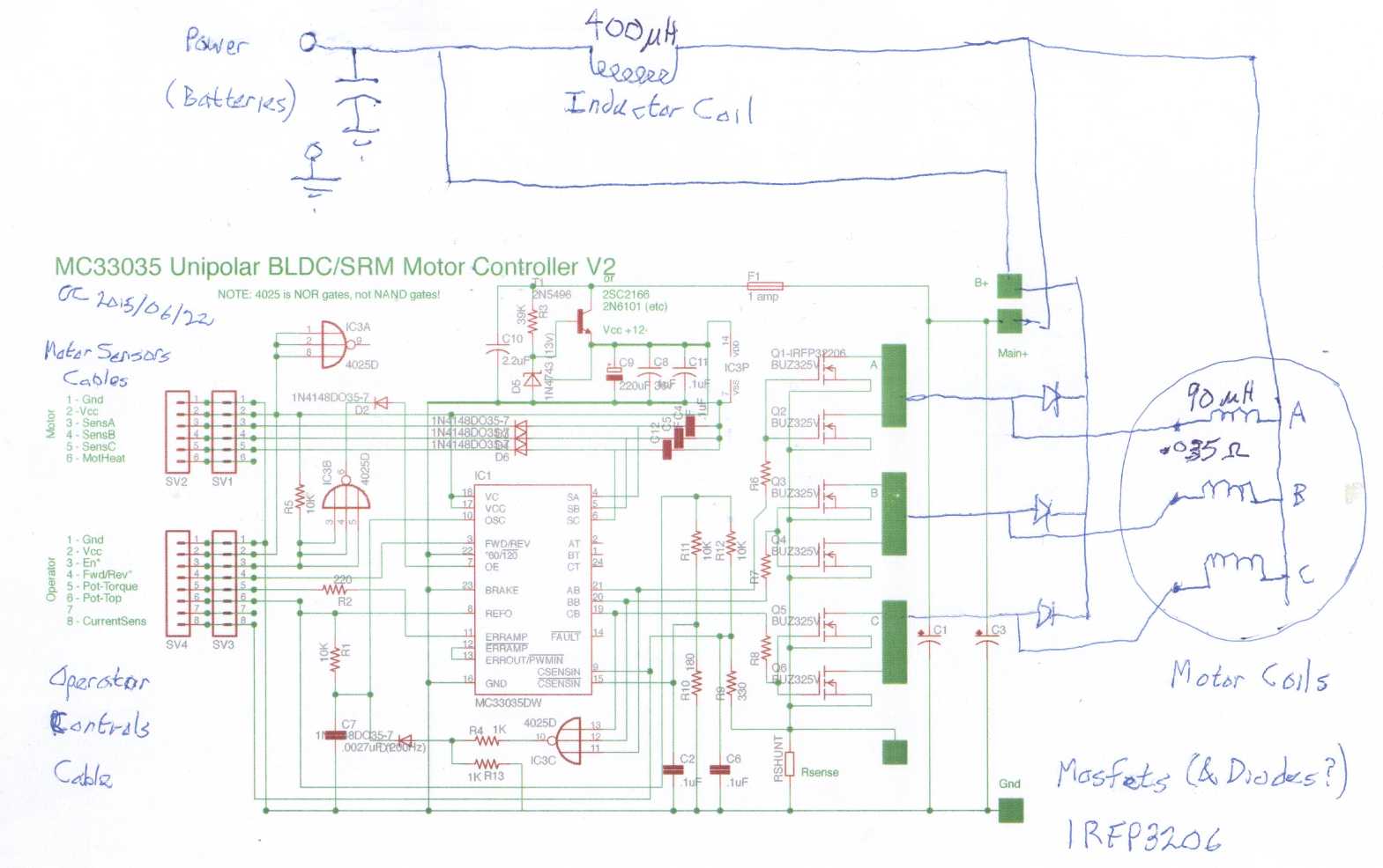 The initial "Version 2" motor controller schematic,
with corrections from version 1.
The initial "Version 2" motor controller schematic,
with corrections from version 1.
Note that the variable frequency modulation circuit section (4025D gate
C et al)
was disconnected during testing, and is untested at this point.
Full Circle
Also on the morning of the 19th, when cleaning up I ran
across my magnet rotor diagrams that I'd used in figuring out whether
the new Electric Caik phase sequencing made sense. In 2008 the first
motor wouldn't run and I had concluded that the magnet configuration
had to be two magnet poles per three phases instead of four per three,
and I
had never since questioned that conclusion. It seemed to be supported
by the fact that every diagram of a BLDC motor I've ever seen has two
rotor
magnet poles per three electrical phases. But somehow as I looked this
time I saw that this was wrong: there was no reason four per three
shouldn't work if the optics and power phases were in sync. Apparently
I'd been laboring under a false pretense all this time!
It would switch coils twice as fast, and it should have a
higher Kv and probably more torque per amp since the rotor magnet field
changes were closer together and closer to the active coils. To verify
this would work, I'd have to make up an adapter cable for the magnet
sensors and perhaps use some aligator clips for the power wires, and
hook up a regular motor controller to the new 4:3 Electric Caik to try
it out.
Still, the new controller has 1/2 as many driver
transistors and diodes, so it should make less internal heat and be
more efficient, and of course it's also intrinsically more reliable
with no chance of shoot-through currents. It's surely better. So just
what was the point of
this realization? Academic, perhaps.
How balanced is the question? With the bipolar controller,
current is flowing through two active phases of the three, while with
the unipolar, it's only through one. For current "X" the bipolar one
creates twice the torque. But heat is the limiting factor, and in the
unipolar controller each phase gets to rest 2/3 of the time instead of
just 1/3, so the current in the on phase can be higher without
the motor getting any warmer. One thinks that "I squared R" losses must
be higher with higher currents, but the coil resistance is for a single
phase instead of for two in series, so "R" is half, so current can be
square root of two higher with no more losses. I wonder if all this
doesn't approximately or even exactly cancel out to yield roughly
similar or even theoretically identical motor performance. In that
case, what's left
is
the reduced motor controller losses, and improved reliability. And
the new controller will run a switched reluctance motor as well - "two
birds with one stone" as they say.
Now, about
that Switched Reluctance Motor
A steel bottom plate &
AFSRM rotor with thrust bearing
The successes with the new configuration of
BLDC motor and
the unipolar controller didn't stop me from thinking about the SRM. I
decided the designs in the papers I'd read weren't quite what I wanted.
The Japanese one had huge torque to direct drive a vehicle wheel, and
low RPM. But the real advantage to the SRM, it seems to me, is in
having a solid rotor that can spin effortlessly and safely at
many thousands of RPM. The need for huge torque is then eliminated by
reduction gearing. If a vehicle like the Chevy Sprint needs 200
foot-pounds, a wheel motor with a 10 to 1 toothed belt reduction needs
only 20 foot-pounds. (Or two motors with as little as 10 foot-punds
each.) And if designed as I envisioned it so the reluctance changes
more smoothly instead of going for a maximum torque at a single point,
surely
the torque ripple could be relatively small. If a motor is directly
connected to a drive train (no clutch), the minimum torque is where
it'll sometimes have to start moving from.
I decided I would build one, and that it would be the sort
of
design I had first envisaged, as modified by realizing that the flux
gaps must be tiny instead of huge, and that therefore it all has to be
constructed differently, all
precision built and everything must align perfectly. Successful
performance will hinge largely on a carefully planned and well
implemented physical/mechanical design.
I like the two rotor idea, but it's much more difficult
because it's hard to make a solid stator when it's full of wires and
cores that extend the full height, and yet make it solid enough to
mount from the outside edge, and perfectly flat on both faces. For a
single rotor design, it'll start with a flat metal platter for a base -
not
just randomly "flat" plate steel but unless it's already truly flat,
hammered flat (if that works well
enough) or
machined flat on the lathe. The toroid coils sitting on these will be
carefully wound with two layers of #11 wire (20 turns) so that the
wires don't protrude over the top or bottom by even a fraction,
anywhere. Their sheet steel outer rings will be epoxied around the wire
windings, held in place with cable ties until the epoxy sets. The inner
lips of the toroids curve smoothly out at the top, and I would machine
pieces (plastic?) that would fit over these curves to hold the coils
against
the platter without themselves sticking up above the coils, using
flat-head machine bolts. If that's not stiff enough, it could all be
glued together with epoxy.
Once finished, this entire assembly would be sanded flat
on a belt sander to ensure nothing was sticking up. The center of the
platter could be machined to hold a needle bearing dead center at a
fixed height, holding the rotor 1/2 a millimeter above the coils.
I got started with slightly turning down a curved edge
that almost fit the thrust bearings I had bought so that it did. I
played around a bit with other pieces, seeing how they might be fitted
together. Then I moved on to other equally worthwhile things and I may
not get back to this before next winter.
"Green" Electric Equipment Projects
Vertical Axis Lathe for Large
Diameter Pieces
This is just an idea that resulted from answering an e-mail...
Craig,
Sounds good.
What do you think of the design of the alxion rotor and stator?
longer magnets and coils in a drum configuration.
Getting a centered drum for the magnets may be tricky.
r
I thought they looked very nice. The drum would
probably be done on a lathe,
Here as I typed I thought of what a huge machine lathe would be
required to
turn a drum of the required diameter, and that something else might
be rigged up... probably with the workpiece horizontal on a table.
or some
device that would be used as a lathe.
There it was: Take a vertical
axle that could
mount and spin the workpiece. Add an appropriate lathe tool rest that
sits
by the outside rim, and a sturdy metal bed or frame connecting them,
and one would have a vertical axis lathe that would be used for turning
large
diameter objects like drums, disks and large pulleys! Where a
huge horizontal axis lathe is needed to do large diameters, the working
length of a horizontal axis lathe is the radius that can be turned. So
if it
was even just 18", one could turn a disk of up to 3 feet in diameter.
Even the Electric Weel motor, much the biggest thing I've done, is only
28" diameter with a 26" rotor. Surely some small and simple vertical
lathe for relatively narrow rotor, disk and pulley shapes could be
easily made?
It wouldn't be needed for small disks that can be done on
a small
regular lathe, so it would only need slow turning speeds with lots of
torque, just a few pulleys with a very large one(s) under the axle.
Perhaps flat belt pulleys?
In essence, initially I was only thinking of a fairly
simple tool mounting at the outer
rim to shape and center the outer rim area, not to profile the whole
top face or work
near the center.
But that could be done too. A fixed gantry could fit over
the whole unit not only for milling the top surface, but to allow tools
to be
positioned at any radius over the top surface. The part could
accurately be rotated to any angle and clamped, to drill holes centered
on the axis, for example mounting holes for car wheel or other 'stud'
bolts. A large diameter could be hard to stabilize to the required
extent for milling, so the area under the tool, just inside the outer
rim, might have an adjustable but very stiff wheel (or two wheels, one
before and one following the tool) contacting the bottom of the
workpiece to prevent it from being pushed down by the tool. As I see
it, the tool working from the edge would initially mill a small
machined-flat lip underneath for the wheel(s) to run true on. (The
Electric Weel project has shown me how much a bit of play magnifies as
the diameter is increased!)
I had never heard of such a thing, but I checked on the web. Wikipedia
just mentioned vertical axis lathes (not even a picture!), but e-bay
had quite a few for sale. Lathes need to
be very sturdy and inflexible, but everything I saw looked way
overbuilt and overpowered compared to what I was thinking, and wouldn't
fit in my shop without removing most everything else. Only one unit was
under 10000$ and they worked their way up from there to 350000$. A Fuji
unit I looked at was about 6' x 6' and taller than long, was about 25
horsepower, and only did pieces up to 16" diameter (but quite tall).
Others could do gigantic pieces up to 9 meters diameter.
Gearing down, as with the belt and a very large pulley, should
be the
key to reducing horsepower requirements for milling the large
diameters. The stabilizer wheel(s) is probably the key to reducing the
requirement for a long, fat axle and huge bearings to attain the
required precision.
As if I needed more projects! But maybe somebody else will
like the
idea... or just maybe I'll have to make one for doing motor or drive
work myself. My own lathe will turn up to a 10" diameter workpiece if
it's narrow. (larger than many!) If I can just stay under that I should
be okay. It's just larger flat belt pulleys (which I'm pretty sure I
want), and potentially larger motor rotors, that pose a problem for
which this could be a good solution.
Aquaponics the
Manual Way?
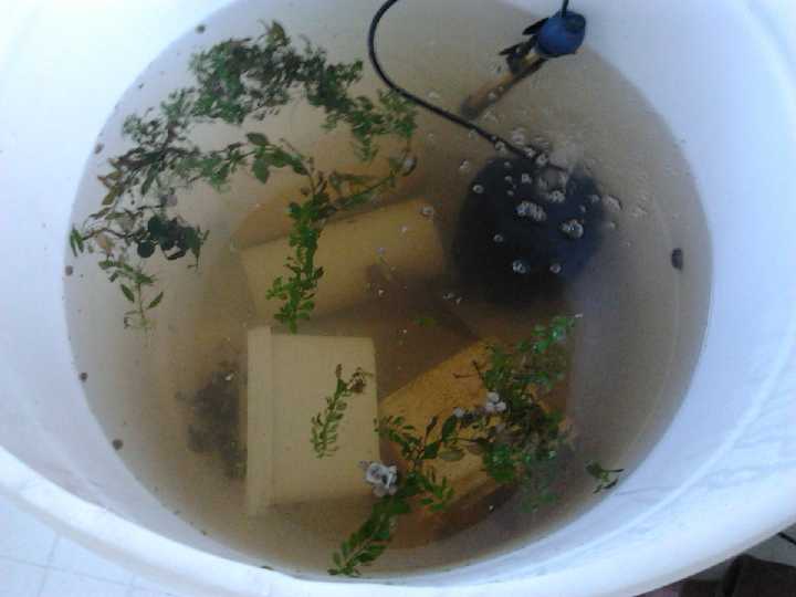
After the dreams of mopping up a flood, I disassembled the upturned
fridge aquaponics system and transferred the two remaining tilapia to a
220 litre HDPE drum with the top sawed off, which made a better fish
tank.
The water in the aquarium started to smell bad, and it had
got so murky you could hardly see the fish. Being busy with other
things, I didn't do much about it. I put in some "aqua-clear" and
changed a little water. One morning two of the three fish were dead.
(The pH was 7+.) Not much of a fish farmer, I! I quickly transferred
the survivor, the big female, to a 10 gallon aquarium and added fresh
water to it. Over a couple of days I changed most of the water.
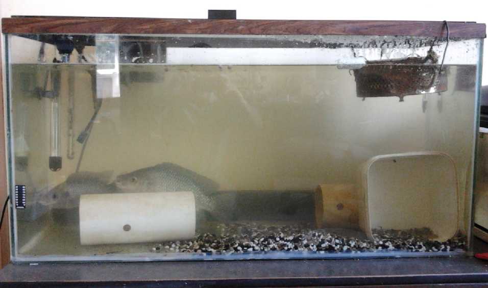
Then I took the whole (30 gallon) aquarium outdoors and
cleaned it out. I brought it back and filled it with tap water (and a
little fish drum water to get bacteria started) since there was no
really clean rain water. (The chem spraying saw to that.) My brother
said chlorine dissipates in a day, so after a day I put the two fish
from the drum into it. One of them I thought didn't look very well even
before I moved it, and it died in a few hours after moving it. I don't
know if it was already that unwell or if it was the move. I had fish
burger dinner the next day. The other was fine. I was now down to two
large tilapia, the female for some reason twice the size of the
remaining male, and the one remaining offspring of the largest.
A day later I put a coated wire fridge-shelf barrier in
the aquarium and put the big female in the other end. This seemed to
get the male very excited, but the female hadn't looked well in the 10
gallon tank and didn't look at all well now. I feared it would die
like the one the previous day. The next time I came in, the fridge
grill had been shoved aside and both fish were together. The female
seemed to recover after a couple of days, but for whatever reason was
much less aggressive
than before, and the two fish behaved like great pals.
The small tilapia in the small tank beside the big one was
now 6" long, and on the 18th seemed to be trying to get through the
glass to join the other two fish. So I put the fridge grill back in,
towards one end, and transferred him. (From the bucket to which I was
slowly adding water from the target aquarium to acclimatize him, he
took a jump, but cleared the whole aquarium and landed on the floor. I
wet my hands and scooped him up. He flopped out when I'd almost reached
the water and it took another try. Hmm... I could have used the net.)
He was okay. Now I would just have one aquarium to deal with until
and unless there were more young.
The fish still pushed the grill aside and the small one was often seen
with the others. But they had a couple of pipes to hide in, and none
seemed aggressive like before, for whatever reason, despite, or because
of, being three distinctly different sizes.
In the aquaponics setup the water gets cleaned of nitrogen
compounds as it circulates through the plants, but in the aquarium they
just build up until toxic levels are reached. The obvious thing to do
is to replace some of the water frequently with tap water (or clean
rain water if available), and use the removed "fertilizer water" either
in a manually watered aquaponics grow bed or outside to water the
garden. "Manual aquaponics." Something just doesn't sound right about
that.
On a related note, birds or some animal ate the wheat
seeds I planted after tilling where the pool had been, and nothing came
up. I replanted part of it and buried the seeds a little deeper. The
wheat is now nearly a foot high. I planted some quinoa in a couple of
rows, but I don't see anything forming rows. It doesn't help that I
don't really know what it looks like.
Electricity Storage
Turquoise Battery
Making Project
Cylindrical Battery
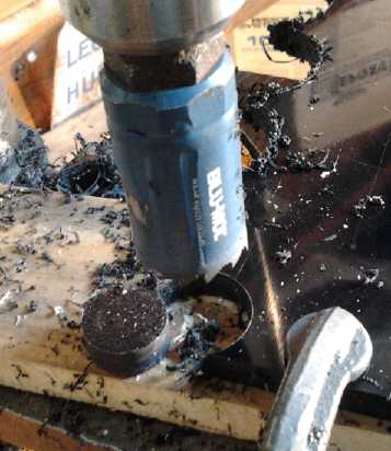 I finally got
back to this on the 15th while waiting for a
new oscilloscope for the unipolar motor controller project. Not wanting
a big ugly pipe cap on the end of the battery, I found a hole saw that
I had already made for something long ago, to cut disks that were just
about the right size (with just a little filing) to make internally
fitting end caps for the 3/4" PVC pipes for the battery cases. I cut
one
out of ABS, filed it to fit, dripped methylene chloride on it and
hammered it into a piece of the PVC pipe. This pipe was then a bit too
short because the internal cap took up its thickness, 3/8". So I did
another with a slightly longer pipe. I decided for this cell at least
that both electrode posts would come out the top to minimize any chance
of leaks at the bottom.
I finally got
back to this on the 15th while waiting for a
new oscilloscope for the unipolar motor controller project. Not wanting
a big ugly pipe cap on the end of the battery, I found a hole saw that
I had already made for something long ago, to cut disks that were just
about the right size (with just a little filing) to make internally
fitting end caps for the 3/4" PVC pipes for the battery cases. I cut
one
out of ABS, filed it to fit, dripped methylene chloride on it and
hammered it into a piece of the PVC pipe. This pipe was then a bit too
short because the internal cap took up its thickness, 3/8". So I did
another with a slightly longer pipe. I decided for this cell at least
that both electrode posts would come out the top to minimize any chance
of leaks at the bottom.
I then took the gum arabic
mixture and some of the fine
nickel flake/powder and mixed them together into a paste. I painted
some onto the inside of the etched cupro-nickel sheet metal tube. It
seemed like a pretty thin layer, so I let it dry and repeated the
process, working quickly enough that [I hoped] the first layer wouldn't
soften again.
With the nickel-rich micro-convoluted etched surface on
the sheet of conductive cupro-nickel, and the mass of conductive
micro-fine nickel flake jelled in gum arabic, I think it should be a
mighty fabulous electrode!
 For the
'posode', I shredded some graphite felt by hand, which I
planned to add into the powder to improve conductivity. Then I felt
little bits pricking my legs right through my pants, as if I had been
working with fiberglass
or carbon (graphite) fiber. A magnifying glass confirmed that the felt
fibers were long and fine, same as carbon fibers. How did I expect them
somehow to be soft cloth of some sort?
For the
'posode', I shredded some graphite felt by hand, which I
planned to add into the powder to improve conductivity. Then I felt
little bits pricking my legs right through my pants, as if I had been
working with fiberglass
or carbon (graphite) fiber. A magnifying glass confirmed that the felt
fibers were long and fine, same as carbon fibers. How did I expect them
somehow to be soft cloth of some sort?
 Then I cleaned the carbon
terminal rod off (from an 'F'
dry cell), and went to paint some osmium doped acetaldehyde on it to
improve the surface conductivity. But the tiny remnant in my little
test tube had finally dried up. I'll have to look it up to make some
more,
since I've only made it once, in, um... 2010?
Then I cleaned the carbon
terminal rod off (from an 'F'
dry cell), and went to paint some osmium doped acetaldehyde on it to
improve the surface conductivity. But the tiny remnant in my little
test tube had finally dried up. I'll have to look it up to make some
more,
since I've only made it once, in, um... 2010?
That was as far as I got before my new oscilloscope
arrived and I went back to working on the new configuration BLDC motor
and unipolar motor controller. And I didn't want to deal with the
carbon fibers.
Leonardo e-mailed on the 8th that he had sent me the
'ethaline' DES! It'll be great to try it out and see how it works in a
cell.
 On the 26th I decided to make the positive electrode, without the
shredded graphite felt. I just didn't want to touch it. And forget the
doping - just get something that hopefully works together, even if the
current drive is lower. People want it!
On the 26th I decided to make the positive electrode, without the
shredded graphite felt. I just didn't want to touch it. And forget the
doping - just get something that hopefully works together, even if the
current drive is lower. People want it!
It took about 40g of positive powder, to which I added
around a gram of Sunlight dishsoap and 3 grams of Dieselkleen and mixed
it up. I pressed it to 2 tons, then put it at an edge and pressed the
whole thing out of the pipe. There were problems with pieces breaking
off, including the bottom but mostly at the top, and more of them when
I tried to insert the carbon rod. I filed the little bumps off the rod
and it went in freely. I wetted a piece of Arches watercolor paper to
make it pretty limp, and wrapped about 2 complete turns of it round the
electrode. Then I cut part of the bottom away and folded the rest over
the bottom, covering the bottom of the electrode.
 When I went to
insert it into the outer nickel metal
electrode, it was a tight fit, and I spread the sheet metal cylinder
apart some more with a spoon; then it slid in okay.
When I went to
insert it into the outer nickel metal
electrode, it was a tight fit, and I spread the sheet metal cylinder
apart some more with a spoon; then it slid in okay.
And the entire
assembly slid into the outer PVC pipe shell okay. That left the top
still open, and the 'stuff' stuck up right to the top. I decided that
instead of trying to fit any solid top, I would just paste in RTV
cement or heat glue over the whole top, which wasn't a very big area.
Or maybe pour in melted wax?
But I was too impatient for any of those things. I added
(15ml?) KCl electrolyte and measured the voltage: .50v. Then I hooked
it to the power adapter to charge through a 50 ohm resistor (~20mA),
and the charge voltage was soon over 1.5v. I changed to 100 ohms
(~12mA) and then 200 (~6mA) to keep the charge voltage down. It seemed
I had one more poorly conducting cell. Then I melted some wax and
covered the top.
Soon it occurred to me that I had used posode mix I made
before I had got the carbon black. (It even said "2013/10/20" on it. I
should date them all!) It had the old impure art store graphite in it
instead - at least, the carbon content was simply labeled "C". With no
qualifying explanation, that would be the old art graphite. Oops!
Wasn't that a main cause of self discharge? (This is of course what
happens when you work on something so seldom - the finer details are
forgotten!)
As now expected, over the hours of charging the self
discharge wouldn't go away. I guess this was just another
unsatisfactory test cell. The remainder could go out to the compost
pile to add trace minerals to the soil. I found another jar with a
similar posode mix but having no "C" on the label. (Rats, no date.)
Presumably I could add carbon black instead of graphite to that.
I decided to scrape off the wax, grab the cupro-nickel
sheet with small pliers, and take the first cell apart to re-use the
shell and the negode. I couldn't get a grip on the sheet metal around
the rim, but finally I grabbed the carbon rod, which had been loosely
inserted. It was now quite tight and I pulled the assembly out of the
pipe with it. The part about the posode swelling and tightening up
around the carbon rod, inserted rather loosely, seemed to have worked
great.
 On the 30th I
got back to it. I put in 26.7g of the powder
with no carbon, intending to make it 40g with conductive carbon black.
But the carbon black was so light and fluffy that I only got up to 30
grams, and visually it looked like over 50% carbon black by volume. No
doubt it compacts far more than the active materials. I added a 1g of
Sunlight, 2g of Diesel Kleen, and 4 or 5 grams of water to dampen it
further. I used it all in the pressing, which again didn't go smoothly,
cleanly or nicely. When it came out of the press, again it crumbled and
broke when the nail was pulled out. It lost maybe 5g of crumbled
material off the top. I can see there's a number of changes and
additional tools and jigs needed before making any quantity of cells.
This time I decided to leave it to dry before trying to make a cell.
On the 30th I
got back to it. I put in 26.7g of the powder
with no carbon, intending to make it 40g with conductive carbon black.
But the carbon black was so light and fluffy that I only got up to 30
grams, and visually it looked like over 50% carbon black by volume. No
doubt it compacts far more than the active materials. I added a 1g of
Sunlight, 2g of Diesel Kleen, and 4 or 5 grams of water to dampen it
further. I used it all in the pressing, which again didn't go smoothly,
cleanly or nicely. When it came out of the press, again it crumbled and
broke when the nail was pulled out. It lost maybe 5g of crumbled
material off the top. I can see there's a number of changes and
additional tools and jigs needed before making any quantity of cells.
This time I decided to leave it to dry before trying to make a cell.
 On Canada day I torched it for a few seconds, wetted a
piece of watercolor paper and wrapped it, slid it into the outer
negode, and slid it all into the PVC pipe. It didn't seem to want to go
in much farther than flush. That was annoying and there seemed to be no
reason for it. I left it that way, paper sticking out, and added a
little salty (KCl) water. I hooked it up and started charging at ~10mA,
soon at 1.35-1.4V. Once again higher currents seemed to overpower it
and the voltage went way up, so I couldn't charge any faster.
On Canada day I torched it for a few seconds, wetted a
piece of watercolor paper and wrapped it, slid it into the outer
negode, and slid it all into the PVC pipe. It didn't seem to want to go
in much farther than flush. That was annoying and there seemed to be no
reason for it. I left it that way, paper sticking out, and added a
little salty (KCl) water. I hooked it up and started charging at ~10mA,
soon at 1.35-1.4V. Once again higher currents seemed to overpower it
and the voltage went way up, so I couldn't charge any faster.
After 12 hours, the center post seemed solid. But when I
disconnected the charge, the voltage still dropped off markedly and
continuously. It didn't look very promising, and stayed that way. What
am I doing wrong? I was doing better with the NiMn, at twice
the cell voltage!
http://www.TurquoiseEnergy.com
Victoria BC Canada