Turquoise
Energy Ltd. News #90
covering July 2015 (posted August 2nd)
Victoria BC
by Craig Carmichael
www.TurquoiseEnergy.com
= www.ElectricCaik.com
= www.ElectricHubcap.com
= www.ElectricWeel.com
Highlights: BDLC 4:3 Motor and
Controller: A superior BLDC system, prototypes finished and working
Month In Brief
(Project Summaries)
- BLDC4:3 Motor & Unipolar Controller - an order for CAT 12VDC
plugs,
sockets, wall plates! - fickle ceramic capacitors - Variable
transmission/Chevy Sprint progress (with Kelly BLDC motor controller) -
DES battery electrolyte (I'll make
it, I hope) - Electric Caik Outboard/fishing/anemometer for boat speed
- Motor failures - Kia Soul production EV.
In Passing
(Miscellaneous topics, editorial comments & opinionated rants)
- Resistance to Change - Greek Example - PETE/PET is burnable plastic - Life in the Solar System... On
a Comet? - Pluto - More on (Ugh!) Chem Spraying
- Turquoise Energy taxes/SR & ED 2014.
- In Depth Project Reports -
Electric Transport - Electric Hubcap Motor Systems
* "BLDC4:3" Electric Caik Motor and Unipolar Controller
* Variable planetary gear transmission with Centrifugal clutch in Chevy
Sprint
- Installation in car
- Kelly Controller over-revs motor with old magnet attachment
- Will replace rotor... with BLDC4:3 configuration and good for
much higher RPM.s
* Electric Caik Outboard: fishing trip & problems -
planning next improvements
* Copenhagen Wheel Electric Bicycle Wheel - link et al
* Original GMC EV1 Brochure (attached)
Other "Green"
Electric Equipment Projects (no reports)
Electricity Generation
(no reports)
Electricity Storage - Turquoise Battery
Project (NiMn, NiNi), etc. (No reports)
No Project Reports on: Magnet
motor,
Lambda ray collector, evacuated tube heat radiators, CNC
gardening/farming machine, Electric Weel, battery making, aquaponics.
July in Brief
July was almost solely about electric transport systems
for a change. Except that I wrote quite a lot in In Passing.
There were some interesting space mission news
items that I give my take on, in particular the Rosetta
mission to comet 67P/Churyumov-Gerasimenko with its lander Philae.
Readings
on
the
comet's surface appeared to indicate there was life on
it, according to astrobiologists Chandra Wickramasinghe and Mike
Wallis. And of course, the New Horizons probe flew past Pluto
after a 9-1/2 year flight, revealing some interesting stuff on a tiny
world. And I wanted to cover peoples' powerful resistance to change as
related to world politics and social order or the growing lack thereof.
And the almost global northern boreal forest fires of early July,
probably caused mainly by drought owed to chem spraying, led me to
reluctantly comment on that subject again.
BDLC 4:3 Motor and Controller
I started the month with an experiment, a development and some testing
of the new BLDC motor and unipolar motor controller configuration.
More inductance seemed to make minor
difference to the energy recirculation characteristics. Later I got the
"CRM", "current ramp" variable frequency modulation, working. That
completes the essential functionality of the BLDC4:3/SRM motor
controller.
I have now to make something more along the lines of a
"production prototype", which I thought would need a bigger circuit
board owing to the addition of several large capacitors for better
filtering. (And that might not be doable with the "cheap" Eagle PCB
license. The full license as I recall isn't cheap.) Later I decided to
mount and wire the mosfets and capacitors off-board (the mosfets screw
to copper bars anyway), which actually shrinks the board instead.
Another aspect is the 'active generator' system both for
regenerative braking and for the Weel hydro generator. I've been
assuming that one simply drives the motor in the opposite direction to
the one it's turning in, and the back EMF adds to the voltage instead
of subtracting, so the energy in the coils will be higher than what was
put into them, so more will come out than went in. But I went to the
July EV club meeting, and someone from Australia who has been
converting cars since the 1970.s (!) said the Mitsubishi iMiEV had
better regenerative braking than all the others, and that people were
trying to reverse engineer it and figure out how it works. And I
remember being disappointed by the current being returned during
braking in a converted Sprint I tried out at Canadian Electric Vehicles
a couple of years ago, compared to what went in to speed it up. I
assumed at the time that the reason was mechanical losses - the lossy
automotive transmission. But maybe that's not the whole story! I hope
my setup will produce good results. There's some chance it'll work
better because the return energy circuit drains the coil energy to zero
volts (plus one diode forward drop) instead of just down to the power
supply voltage (plus two diode drops).
Then I decided "active rectification" would help in the
energy recovery circuit. The diode forward drop was too high and
causing them to heat up. Heat isn't just a nuisance to dissipate, it's
lost energy. In "active rectification" the mosfets are turned on just
in the instant the motor coils return their stored energy to the power
supply, making it a much lower resistance path hence with low voltage
drop. On the night of the 17th I figured out a "self switching" circuit
(several discrete components) to have then turn on at the exact time of
the turn-off pulse and only then, and over the next two days I layed
out a circuit board to solder to the feet of the diode-mosfets, which
are bolted to a copper bar. On the 24th, in looking for additional
information about synchronous rectification as applied to regular BLDC
motor controllers (trying to find some theoretical info to help
determine whether my controller would actually be better
or not), I found a chip (IR1167) that drove mosfets specifically as
synchronous rectifiers, doubtless better than my circuit of discrete
components... but they cost over 5$ each - ouch! And they hardly reduce
the component count.
CAT 12 VDC Wiring System
 On the 8th I
got another order (Kansas), this time for a
good number of CAT plugs, sockets and wall plates for an off-grid
dwelling. They said they were pleased to see there was something better
than the car "cigarette lighter" types. Alright - that's why I created
them! I fired up the 3D printer on the 11th and started printing them
all. It became obvious that I needed something to just punch out the
blade pins for the plugs, as the whole order and especially those took
much to long to put together. (Even aside from that I'll have to raise
the prices a little.) And I'd really like to find something better than
the easily-bent, poor grip, Pico zinc coated (unsolderable!) .205"
socket pins. I did find some later in the month - gold plated in fact -
but they came in little packages of just a few with rubber insulating
"boots" that I have no use for, for a relatively high cost, instead of
in bulk. But perhaps if I search I can order some in bulk, or find some
others?
On the 8th I
got another order (Kansas), this time for a
good number of CAT plugs, sockets and wall plates for an off-grid
dwelling. They said they were pleased to see there was something better
than the car "cigarette lighter" types. Alright - that's why I created
them! I fired up the 3D printer on the 11th and started printing them
all. It became obvious that I needed something to just punch out the
blade pins for the plugs, as the whole order and especially those took
much to long to put together. (Even aside from that I'll have to raise
the prices a little.) And I'd really like to find something better than
the easily-bent, poor grip, Pico zinc coated (unsolderable!) .205"
socket pins. I did find some later in the month - gold plated in fact -
but they came in little packages of just a few with rubber insulating
"boots" that I have no use for, for a relatively high cost, instead of
in bulk. But perhaps if I search I can order some in bulk, or find some
others?
I have no idea whether people I don't know are adopting
the CAT system - of how many CAT wiring items may have been
made overall since I posted the 3D printing files for them at
"thingiverse.com". Anywhere between zero and a few thousand, I suppose.
Capacitor Variances
Someone wrote to the OSMC list on the 10th about how
variable and amazingly far off the printed value larger ceramic
capacitors can be, depending on temperature and applied voltage. He
gave a link to a web site on the subject: http://www.maximintegrated.com/en/app-notes/index.mvp/id/5527
I
had
never
seen
this
in
my
electronics courses or elsewhere, and I had
paid no attention to the mysterious three symbol sequences often seen,
like "X7R" and "Y5V", that indicate tolerance curves.
Variable Torque Converter Transmission - Chevy Sprint
Also on the 10th I decided I really had to get on with the
long delayed variable planetary gear transmission with centrifugal
clutch in the Chevy Sprint. I do very much want the improved EV! I
wasn't particularly confident it would
work, but it had been mostly ready to try out since last fall. I
mounted it
in the car and then started in on figuring out the wiring and
installing of the Kelly KBL36301X motor controller that I bought for
its 'regular' 2:3 BLDC motor last September. On the 13th I finally
removed the gas tank, just because it was now in the way, and I ran a
heavy 'cab tire' battery cable so I could have the batteries in the
back, where they'd be convenient at least for testing.
When I started in on the controller, I realized the 12V
relay I had should be 36V, and that I'd want an ampmeter and a few
other bits and pieces. So I ordered them from KellyController.com .
They
came to around 300$ where I had hoped 100 - 200. Everything adds up.
While I waited for the parts, I contented myself with
figuring out what batteries to use and where to mount them, and
changing the car's light bulbs to LED "bulbs". I ran out of 1156 and
1157 bulb socket LED.s and had to order more of those too, from DX.com.
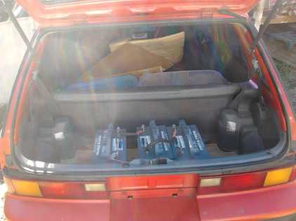 For now the batteries are just three size 27 RV
batteries in the back on a sheet of plywood.
The Kelly parts arrived on the 21st.
I got curious about the shunt material. Apparently an
alloy called manganin (Cu:Mn:Ni ) has a very stable resistance over
temperature and is the substance usually used for electronic resistors
including shunts.
It replaced an earlier alloy called constantin (Cu:Ni 60:40) that
was good but not as constant. Both were created by the same person,
Weston, in
the late 1800.s. I note that constantin is close to the same formula as
the cupro-nickel 70:30 that I bought for battery electrodes, so perhaps
I'll try making my own shunt resistors from that.
After a couple of weeks wiring and making up a "panel" for
the Kelly controller, I was ready to test on the 31st. After sorting
out a small problem with the Kelly handheld controls box, I ran the
motor. Everything worked right, except that the slightest turn of the
throttle potentiometer would send the motor racing at high RPM. After
running it forward and backwards a just a few spins (verifying that
everything worked right), the over-revved motor suddenly seized. The
magnets, as a group with their epoxied polypropylene strapping, had all
come detached from the rotor and flung out against the outer rim. So I
didn't get to do any further testing, much less to hook up the control
pulley and try out the transmission. This motor was put together in
2011 or early 2012, and it had the zinc coating that I later learned
would delaminate easily, and of course the original strapping
arrangement. The later techniques are much better.
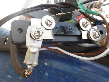
 The magnets complete with their PP-epoxy
strapping flew off all the way around the rim.
The magnets complete with their PP-epoxy
strapping flew off all the way around the rim.
Only magnetism holds now them to the rotor.
The new magnet mounting techniques should put an end to this sort of
problem,
even at much higher RPM.s.
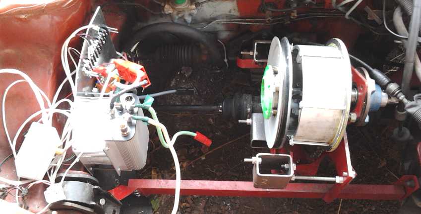
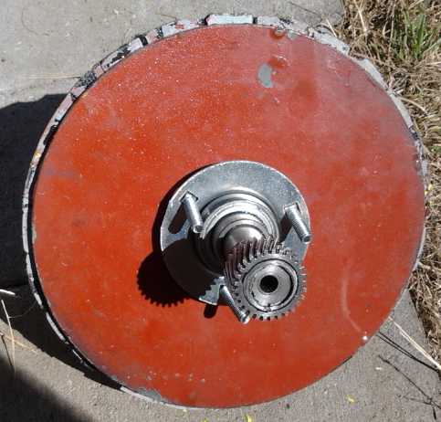
The Transmission (with planetary gear variable torque converter
[without slip pulley cable] and centrifugal clutch),
plus Kelly BLDC controller and various parts mounted on an aluminum
panel.
(Kelly handheld controls box lying to left. Oops, I didn't get a
picture while the motor was in.)
But now I might as well rebuild the rotor in the new
'BLDC43' configuration. And then it'll need the new controller, and
I'll be discarding the Kelly. And all this means, of course... the car
electrifying project needs to await the pre-production unipolar
controller and is on hold again, for now.
Deep Eutectic Solvent (DES) for Battery Electrolyte
The DES that Leonard Elionix said he sent from Italy,
which I wanted to try out in my batteries instead of salt water, didn't
arrive. On the 20th I ordered from acpchem.com the ethylene glycol and
choline chloride that it's made from, to try and make some for myself.
Unexpectedly it was a 350$ order - more money flying out! - as the
choline chloride was about 260$ for a litre. (Hmm... no word from ACP
as of August 1st!)
Electric Caik Outboard - Fishing?
About mid-month I uncovered the boat and put in the
Electric Caik outboard, my (old type) BLDC motor controller, some PbPb
batteries, and the combo volt-amp meter I got from China, intending to
go fishing. The amp meter part had disappointed me, the readings
jumping
around wildly. It was useless with a modulated motor drive. Then it
occurred to me to filter and average out the current to the meter with
a resistor and capacitor across the shunt, 330Ω and 2.2µF
ceramic. This worked quite well, except that the current readings
seemed to me a little low. I changed the 330Ω to 100. It didn't seem to
make
much difference. But now I don't have to hook up, in addition to
everything else, the DC current clamp and a voltmeter to have an idea
of the power being used. (I should however hook one up to find if the
readings are right or if I have to apply a scaling factor.)
 Filtering the shunt voltage gave steady current
readings.
Filtering the shunt voltage gave steady current
readings.
I also bought a hand-held "weather station" especially for
its anemometer. Not only would this be good for checking wind plant
sites, it said it could be immersed in water, which meant it could
measure boat speed - if you didn't fall overboard trying to read it. (I
thought it was in the fishing tackle box. Apparently I've misplaced it
- arg!)
After I finally got a trailer license (50$) and a fishing
license (20$), the days were pretty windy so I didn't go out. 70$ for a
fish or two is bad enough. 70$ for not even fishing is a crime. I
finally went out on the 23rd. I forgot a few things (bait,
anemometer...) and after some time, my line tangled in the propeller. I
couldn't lean over the back so far to untangle it without inviting the
increasingly large waves into the boat, so I rowed back to the boat
launch (I didn't go out too far!), where I managed to untangle it and
retrieve my tackle at the dock.
Then I tried to motor over to the launch ramp to trailer
the boat, and found the motor was seized! And it was hot. The
metal shaft and bearings were quite hot, and the coil bolts were hot.
(The new
model has nylon coil bolts, not subject to magnetic induction.) The
composite body itself felt very warm.
I found the "joy" coupling connecting the motor shaft to
the outboard drive shaft had forced its way down the shaft, pressing
the motor shaft up and the drive shaft down. The latter made gear noise
in the outboard, which I could hear from the start of the trip. Perhaps
I should have paid some attention to it! As it pushed the motor shaft
up, it finally - or eventually - deformed the polypropylene-epoxy end
cover of the motor until the rotor rubbed on the stator wall and
finally seized against it. (I should have paid attention to the slight
rubbing sound I could hear before the trip, too!) Reinforcing the
actual rubbing, a thin gap setting makes the motors run rough and
generate excess heat. The end plate showed little sign of wanting to
flatten out again later. Probably it was only especially pliable when
it was overheated.
The culprit? The set screw in the joy coupling pressed
against the
shaft key rather than the shaft itself. That may be good for holding
the shaft key in place, but it seems like - and has now been proven to
be - a poor arrangement for holding the unit itself in place on the
shaft. I'll
drill another hole and add another set screw, this one to grip against
the shaft.
Sometime it feels like I'm just treading water... I
thought that the outboard, at least, was finished and working pretty
reliably! And my one working Electric Hubcap motor's rotor - albeit
from early 2012 and older methods of fastening the magnets - flew
apart. Other things now need work too, like there's a "burning rubber"
smell in the RX7-EV after 3 or 4 miles, and the Tercel seems to need a
new brake cylinder, as well as jobs always getting behind around the
house. At least I got Turquoise Energy's 2014 income tax/SR & ED
claim done.
Anyway I'll look on these component failures as creating
the opportune time to change all my motors over
to the new (and I believe superior) BLDC4:3 magnetic configuration,
with the new (and superior) unipolar controller, and
with the new improved magnet strapping technique, safer for higher
RPM.s. 4500 RPM for the Caik might just get the boat up on a plane, and
3000 or 3500 for the Hubcap might just make the difference between
starting the car to move reliably as currently configured, and not! And
I can't help but feel efficiency as well as reliability will rise with
the unipolar controller - synchronous rectification or not.
And when I design the next Electric Hubcap and Electric
Caik motor molds, I'll be looking for every way to reinforce (thicken)
the center
areas where the bearings attach, so they'll be less prone to deforming.
As a final extra note, on the 31st Tom Sawyer said he
wanted to go down and test drive the new Kia Soul electric car.
We drove to the Kia dealer in the RX7-EV and he got his test drive. I
rode along. The regenerative braking seemed good. Of the production
electric cars I've ridden in or driven so far I like this one the best.
It was comfortable, powerful, took bumps well, and had nearly a 200Km
range. It incorporated novel organic composites like (IIRC) corn-epoxy
in the interior plastic and upholstery. Of course the price, in the
upper 30,000.s of dollars ($C currently =.77$US), puts it way out of my
budget.
And, I still think I can make a vehicle that goes the
farthest on a given battery energy storage. And (if I ever get there) I
still want to do an Electric Hubcap system - or maybe even a
couple of types - that can be simply added to a gas car's wheel. (To
Whit: A BLDC4:3 motor with planetary gear torque converter and
centrifugal clutch (or flywheel), or a high RPM switched reluctance
motor with belt drive to the wheel, per TE News #86.) With my motors
becoming safe for higher RPM.s and the mechanical component development
creeping along albeit at a snail's pace, these things are starting to
look more doable.
In Passing
(Miscellaneous topics, editorial comments & opinionated rants)
Correction: PETE (or PET) Burns Fine
In talking about burning of polyethylene and polypropylene
last month, I mentioned polyethylene terepthalate, recycling symbol "1"
and abbreviated PETE or PET, as being one of the substances that gives
off noxious fumes if burned. But it turns out it's nothing but carbon,
oxygen and hydrogen - a hydrocarbon. According to Wikipedia, it's an
excellent candidate either for recycling (it's made into carpet fibers)
or for incineration.
As long as it doesn't join the gigantic islands of plastic
floating in the oceans, I'm happy. I've been noticing tiny bits of
plastic all around the yard lately, which have been accumulating
semi-unnoticed over the years, and other bits like stickers on fruit,
things you peel off wrappers, packages and jars to open them, and bread
bag closers. Other than burning them, what happens to all those bits?
Resistance to Change
I was disappointed that nobody seemed interested enough to
join an e-mail list that would allow governance of our municipality by
general consensus of involved citizens and probably involving
occasional votes by the populace to be presented to our elected
officials. It seemed so simple
and straightforward to me, and I was sure that once there were a few
subscribers, it would grow of its own accord. I feel we desperately
need to reverse the trend towards autocracy in governments, where there
is an ever-growing disconnect between the agendas and motives of the
elected and the desires of the populace.
But while a few said "That's just what's needed!", no one
at all subscribed. Apparently most people
think the proposals are wild or even crazy. It seems most people
haven't given political/governing systems the sort of thought I have
over the years, and new ideas, however sensible they seem to me, are
alien to them.
"The remarkable
thing about that form of democracy is
that democracy is the last form of the governance that makes rational
sense to large numbers of people. What has not been appreciated
is
that democracies must evolve. Even if it were in existence today, the
skeptics among you would be reluctant to participate, as they think it
would be a fraud." - Machiventa Melchizidek
( My related concept web sites: www.CampaynCentral.com - www.DirectVotes.ca - www.saers.com/recorder/craig/FundamentalDemocracy.html
)
People are born into a system that works a certain way,
and it seems regardless of the systemic problems that ensue, most of
them feel that system is "right", and that it's just the people
involved today that are the problems. 'If we just elect ___ instead of
the present heathen(s), it'll all be fixed.' They don't seem to see
that the reason for an unsatisfactory list of candidates, bad election
results, and why those
elected become
rulers of the people instead of their servants, is because the
procedures, institutions and systems of governance were set up hundreds
of years ago in more primitive times and are badly in need of updating.
They are obsolete and they are gamed by the unscrupulous and power
hungry. Generally,
real leaders and social contributors have been shut out of the whole
process.
Yet people seem to consider their current system -
whatever it is - to be some sort of
"divine order", "set in stone" by some sort of omniscient men of long
ago.
No one today should tamper with them. In fact these systems themselves
were of course
new inspirations once, revolutionary ideas that somehow overcame all
resistance, overcame all the people who thought that they were
"crazy" and those who expected they would surely cause society to
crumble, and got adopted.
The American constitution in particular was revolutionary
at the time, and a truly
brilliant work, but its authors couldn't pre-test the plans or foresee
all the outworkings of the untested ideas they were proposing should
govern the land, nor could they account for the scientific, technical
and social progress that would take place over the next two centuries -
which were in large measure spawned by the freedoms and opportunities
created by the new governing system
itself.
Governing systems need to be dynamic and changing to meet human social
needs as they develop and change. The big problem is that while quality
of life and equality were at least partially taken into account, none
of the
governing systems in use today had or have provision for growth and
change of
themselves as needed. This one of the three cosmic
core values of sustainability is missing.
Here is where a Department of Progress should
exist
within government, to sift and coordinate not only ideas for
technological inventions
but also those of a social or political nature, to be tested perhaps in
local areas, and when a superior way of doing something is found,
presented to the people and to legislatures for enactment - and
modification or repeal if it isn't working out well. The BC
Citizens' Committee on Electoral Reform (~2002-2004) almost got two
electoral reforms passed in one shot. But the committee was formed at
the whim of one premier [~= state governor] for a single shot deal. The
real reform would have been to make it a permanent committee with a
larger mandate to seek out improved ways and means. If they had
continued to exist they could focus on one
smaller change at a time, and some of the better changes would
eventually start getting adopted.
And concerned citizens need to be able
to initiate referendums on any subject, that if passed, legislatures
will then be
expected to act on. If we had had that, the citizens' committee or some
portion of it could have chosen to continue to meet, and independently
of anything else, present their
proposals to the public for enactment. The right to submit a referendum
has brought about some progressive legislation
at the state level in the USA. So far no one has proposed any further
systemic changes, such as adopting the choice ranking vote to make
election results fair and reduce the influence of money and corruption
on the
outcomes, and the initiatives aren't so far available at the federal
level where they would most count, nor at local levels to help resolve
local issues.
But the crux is as usual education and knowledge.
Alternatives need to be invented, presented, and discussed by everyone.
There has to be a general social ferment: it needs to be generally
understood that the changes so badly
needed are needed. As long as most people think the system is fine as
it is, and
don't hear or think about alternatives it's hardly possible to make
real changes... even as everything progresses
towards a social collapse "of Biblical proportions" (as Gregory
Mannarino
would put it on Youtube). Apparently
real and serious suffering will be needed to start that ferment and
discussion.
Change comes, whether it's planned or not, wanted or not.
The US constitution provided that there be one congressperson for each
3000 citizens. Citizens had pretty good control over their
congressional reps. With population growth, by 1911 that made for an
impractically huge congress. Change was essential, but it hadn't been
planned out. Congress simply voted to limit its own size to somewhere
under 500 people. Today, each congressperson represents some 700,000
people. Thus the reps have lost touch with the electorate, and into the
void have stepped lobbying corporations and vested interests, each
putting their own agenda ahead of the public interest.
Greek Example
We see the results of the Greek situation. Political
things are less "overcontrolled" than in the USA, and in January a
rather single platform government promising to combat the austerity
that has been causing so much suffering and perhaps hundreds of
demonstrations in Athens over five years was elected. This was
unexpected by the "power brokers" as the political partisan group
(party) that was elected
only had a few percent of the vote in the previous election. (If the
corrupt who rule behind the scenes had had any inkling this Syriza
party would be elected, you can be sure they would have been in there
interfering with the process to get people to change their minds, and
to corrupt the leadership and members of this party from within. As it
was, an uncorrupted group with real leadership was elected by
surprise.) The first thing they did was tell the truth and admit it
wasn't just a 'liquidity crisis', that "Greece is bankrupt.", which had
been obvious for five years.
Those who made private unsecured loans to Greek interests
in dubious circumstances, those banks who offered "credit default
swaps" to guarantee those doubtful loans, and those who pushed the
Greek government to take responsibility for those loans in order to
protect the investors from losses and their banks from insolvency, must
share responsibility with
those who borrowed more money than they could pay back -- all expecting
the unsuspecting people of Greece to "backstop" and pay for their
reckless gambling. But it is the same everywhere, not just in Greece!
As the money ran out and the next payment couldn't be
made, the Troika's [ECB, IMF, European Commission] only proposal was
for the Greek government to steal perhaps the last remaining unpilfered
monetary asset available in Greece (other than private bank accounts):
Greek pension fund money, and make the next few payments on the
unpayable debt, which would cause still more suffering and solve
nothing, only "kick the can" about five more months down the road. The
government decided they had no "mandate" to accept this proposal,
having been elected to do the opposite, but nor did they feel they
could reject it, having received only 40% support in the election. So
they decided to let the Greek people decide in a snap referendum,
called for only about a week away on July 5th. That wasn't long enough
for Europe to browbeat and threaten the Greek people into submission,
and the result was a pretty solid "oxi" ("no", 61%) to accepting the
Troika's proposal. This was acclaimed as "a victory for democracy" by
many, and as "a circus" and "irrelevant" by the head of the European
commission. (Would he have said that if he had liked the result? He's
an acknowledged critic of the present government, and almost in the
same breath he said "The Greek government should respect the people of
Greece." !?!)
But was it a "victory for democracy"? Why did it take five
years of increasing misery and and a "freak" election result before the
people "were granted" any say in the matter? Why don't they have the
right to initiate a vote themselves, instead of having them only on the
rare occasion when it's convenient to those elected and at their
behest? Does a referendum cost
money? Gosh! How much did keeping insolvent banks open cost? How much
did five years of unproductive protests in the streets, with the people
battling their own police and ignored by
their government cost, instead of having this vote before or when the
government of the day had agreed to backstop private debts with public
money, and long before so much of the Greek people's wealth had been
pilfered away by the central banks? If the banks are going to make bad
loans,
let it be them that go bankrupt, not the population of the nation
they're housed in. If the people had the right to initiate a referendum
themselves, surely this vote would have come years ago.
And why have the American public had no say since 2008
about grossly inflating their money supply to continually bail out
their biggest banks and their unsustainable central banking
institutions? Or Canadians, and other lands' citizens? Surely if "the
silent majority" everywhere had the right to speak and be heard, things
would never have come to this pass in the first place.
Later in the month, Tsipras negotiated a new bailout deal
with the troika, the worst one yet. He completely caved in. Why did the
people of Greece not get another referendum to ratify or reject it? Is
democracy only at the convenience of the elected really democracy?
Life in the Solar System... On a Comet?
First the "fluffy" character of the surfaces of Ganymede
and Callisto were discovered by Earth-based diurnal temperature
observations in the 1980.s. Then polycyclic aromatic hydrocarbons were
found on these same two worlds by the Galileo spacecraft in the
late 1990.s.
They were shrugged off as being "tholins, left over from the formation
of the solar system." (Seemingly ignoring the older "fluffy" findings?)
Then more were found by the Cassini spacecraft on
worlds orbiting Saturn, most notably on the small outer moon Iapetus,
where the leading hemisphere is "very fluffy", dark and organic, and
the trailing face is largely bright ice. (...The term "dark side of the
moon" applies legitimately to Iapetus!) It was noted that this organic
material seemed to have "migrated throughout the Saturn system",
and that Iapetus must resurface itself "at the very most in 100000
years and probably much faster" to have so few bright ice craters on
its dark side. Apparently (in spite of what was said at the time about
it being "highly interesting") the fluffy organics were of little
interest, because
there are no plans for the Cassini to have a close look at Iapetus in
the entire remainder of its mission.
Then this March the Dawn spacecraft reached the
largest
asteroid, Ceres, and found it too was mysteriously dark for an icy
body. No one seems to have reached any sort of conclusion.
Finally, the Rossetta spacecraft has been orbiting
a comet
named 67P/Churyumov-Gerasimenko since 2014, and it landed a probe, Philae,
on
that
body.
After
several
months
of
recharging its
batteries, the probe has come to life and found (guess what)...
polycyclic aromatic hydrocarbons, surely of the same variety as the
earlier missions. Finally, on a little comet, two astrobiologists,
Chandra Wickramasinghe and Mike Wallis, are saying in effect 'There
must
be life there!'
Link to article at RT: http://rt.com/news/271843-philae-probe-comet-life/
(More
at
Wikipedia,
etc, too) From the article:
. . . . .
Wickramasinghe interpreted the data received from the comet as proving
that micro-organisms are “involved in the formation of the icy
structures, the preponderance of aromatic hydrocarbons, and the very
dark surface”.
“These are not easily explained in terms of prebiotic chemistry. The
dark material is being constantly replenished as it is boiled off by
heat from the sun. Something must be doing that at a fairly prolific
rate,” Press Association quoted Wickramasinghe as saying. [IMHO the
dark material surely is the plant life, on the surface.]
---
The European space craft, Rosetta, which is orbiting the comet, has
also picked up unknown “clusters” of organic material that could be
viral particles. [IMHO these are probably the same seeds as the one
picked up by the high altitude balloon above Earth, or seeds or spores
of other species of the same sort of plant life.]
---
However, both Philae and Rosetta lack the right equipment needed
to search for evidence of life. Moreover, the two astronomers revealed
that an earlier proposal to equip the mission with the right technology
to detect life was reportedly dismissed as a joke.
“I wanted to include a very inexpensive life-detection experiment. At
the time it was thought this was a bizarre proposition,”
Wickramasinghe, who was involved in the planning of the mission 15
years ago, said.
---
“Five hundred years ago it was a struggle to have people
accept that the Earth was not the center of the universe. After that
revolution our thinking has remained Earth-centered in relation to life
and biology. It’s deeply ingrained in our scientific culture and it
will take a lot of evidence to kick it over,” Wickramasinghe said.
. . . . .
This comet orbits between Earth and Jupiter with an
aphelion of 5.7 AU (850 Gigameters, slightly beyond Jupiter's orbit),
perihelion of 1.2 AU (186 Gm), with a year of 6.44 Earth years.
Probably at 1.2 AU (1.2 times farther from the sun than Earth) the
comet's water ice will eventually vaporize off and it will then be
unsuitable for this form of airless life, but it spends more of its
time out towards Jupiter,
farther from the sun. If the life originated on Ganymede, that's the
right zone.
What's the difference between a comet and an asteroid? At
least in this case, it would appear to be simply that the comet gives
off a "tail" of volatiles as it approaches its perihelion, while the
asteroid doesn't - perhaps all its volatiles have already vaporized
off, or its perihelion is a little too far out for major vaporization.
At first I didn't think there was much to indicate plant
life visually, then I saw the image below (in a youtube video), which
is full of features that seem highly unusual for dead geography.
Without knowing the exact pixel scale, I'm certain this must be by far
the closest view ever of such a surface. It's certainly convoluted,
seemingly "fractally" at scales down to the limits of resolution, and
too dark to be ice extrusions. My take on it is we're seeing some bare
areas, like glare ice where nothing could grow, and in other places
projections from the surface, in various directions in the very low
gravity, which would appear to be some form of strange, perhaps
"crystalline" forms that look quite botanical in nature, even something
like a forest canopy in a few areas. If the scale were much, much
smaller, one might think it looked like moss; or maybe fuzzy mold.
(What cost,
decent COLOR images of all these many worlds?)
 The surface of Comet 67P
Are there areas that might broadly be described as 'fluffy'?
Could all those strange protrusions (reminiscent of similar forms on
Ganymede, etc.)
be some sort of strange plant life, as the spectral findings suggest?
Pluto
Most readers will have noted that after a nine and a half year
journey, the New Horizons probe flew past Pluto on July 15th
(or 14th GMT) (a world about 1/3 the size [volume] of Earth's moon),
its
small moon Charon, and several other orbiting "oids". It was once
thought to have been the last significant unphotographed body in the
solar system, but while the probe was en route, Mike Brown's sky survey
uncovered several more small spheres, including Xena... I mean Eris,
which is about the same size as Pluto and which orbits the sun far from
the plane of the rest of the solar system in a huge polar orbit 2 or 3
billion miles out. Additionally, Brown had hoped to find a world "the
size of Mars", and recently other astronomers now figure there must be
a couple more worlds way out there to cause gravitational effects seen.
If these are dark in albedo the survey could have missed them.
But back to Pluto. New Horizons had to do a one pass, high
speed flyby because it was naturally impossible to speed the probe up
enough to make this 3 billion mile journey in such a short time and
then to suddenly to be able to match Pluto's stately orbital speed
(other than by crashing into it and making a large crater). Probes to
Jupiter swing by Io, using it as a gravitational brake to help slow
them into Jovian orbit, but no significant body is available at Pluto,
and the relative speed of the probe is much higher.
There is again some dark, perhaps organic matter - small
lines of it in crevasses between polygon blocks of terrain. (Seems
similar to the "cantaloupe" terrain seen on Triton?) Pluto must be so
cold, and dark, it's almost inconceivable anything could live there...
unless gravitational tidal interactions with its moons cause it to heat
up internally. That might explain how dark vegetative material could
form, and why it would be in the crevasses rather than on the main
surface: opposite to the 'almost too warm' comet 67P, they're the only
places with any heat to speak of. Again spectrographic information
hasn't been released so far -- nothing saying it's definitely organic,
much less polycyclic aromatic hydrocarbons -- and nothing has said it's
"fluffy", so it's all in the realm of "very speculative". (But all the
dark stuff everywhere else on airless bodies seems to have those
characteristics.)
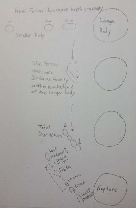 Of special
interest to me is some odd mountainous terrain. In my write-up on the
probable formation of Pluto, its moons, and Triton by tidal disruption
of a larger world that I've called "Pluton", via passing too close to
Neptune (like Shoemaker-Levy 9 at Jupiter), it might make sense that
these odd mountains were formed where two bodies separated, where they
were pulled apart by tidal forces like two clumps of bread dough. If
that is the case, we might also find there are such mountains on the
opposite side of Pluto to the first set -- and nowhere else. (unless
Pluto was the outer end of the original body, in which case there would
only be one area of such terrain.)
Of special
interest to me is some odd mountainous terrain. In my write-up on the
probable formation of Pluto, its moons, and Triton by tidal disruption
of a larger world that I've called "Pluton", via passing too close to
Neptune (like Shoemaker-Levy 9 at Jupiter), it might make sense that
these odd mountains were formed where two bodies separated, where they
were pulled apart by tidal forces like two clumps of bread dough. If
that is the case, we might also find there are such mountains on the
opposite side of Pluto to the first set -- and nowhere else. (unless
Pluto was the outer end of the original body, in which case there would
only be one area of such terrain.)
The terrain is said to be 'young' owing to the paucity of
craters, less than 100,000,000 years old. It's not likely in this case
that this is a result of biological activity. It now seems more likely
to me that the breakup of "Pluton" was a relatively "recent" event in
solar system history, occurring well after most of the original
meteoric (crater making) material was used up, perhaps sometime in
Earth's Cenozoic era. Or maybe one chunk of "Pluton's" material became
the asteroid that apparently crashed into Earth about at the end of the
Cretaceous period and reputedly killed all the dinosaurs,
pterosaurs and ichthysaurs worldwide. (Let me not get into that
specious theory!)
I also cover this subject on my web page, which I've updated pretty
much with what I've said here.
www.saers.com/recorder/craig/pluto/OriginsOfPlutoAndTriton.html
Geoengineering, Chemtrails: Forest
Fires
I wasn't going to mention this subject again, but here we
are. On July 5th I woke up to find everything strangely dark, the sun
hidden by "clouds" and
giving off a weak, orange light. It looked like the whole landscape was
being lit with 40 watt incandescent light bulbs. The sun wasn't visible
but later in
the day could be discerned as a pale orange disk, easy to look at with
the naked eye. Then it was obscured again. It certainly wasn't clouds,
nor did it look like any previous chem spray. LED lights in the house,
and the white computer screen, looked startlingly blueish by contrast
after outdoor light. I couldn't figure it out until someone told me it
was smoke from a forest fire in Washington state's Olympic Peninsula,
just across the strait. The next day it started to thin out and by
nightfall the brightest stars could be dimly seen.
BTW, a correction: It turns out the rumor I heard last
month was distorted. It wasn't the ocean but the fresh water fishery
that was closed, owing to low water levels in lake and streams, and to
allow fish stocks to recover from overfishing. Perhaps nothing to do
with chem spraying unless it caused blooms of algae related to the
decision... except that it's probably the cause of the low water and
high temperatures.
In the tinder dry conditions with low snow pack and melt,
seemingly created largely by the chem
spraying since last winter and its disruption of the northern jet
stream, there are hundreds if not thousands of forest fires, very early
in the season, blazing away and burning up forests almost engulfing the
Pacific Northwest, Alaska, Northern Alberta and Northern Saskatchewan.
Eastern Siberia was literally freezing - in July - while the Western
half was hot
and on fire. On the 6th I heard there were over 200 forest fires
burning in BC
alone. It appears the whole northern boreal forest ecosystem, almost
around the
globe, is being devastated. Weather everywhere is exceptional - wildly
out of wack.
And still the distant rumble of the heavy jets
continues - I heard three distant takeoffs as I initially wrote this
article, and I saw countless chemtrails over the month.
One day I saw one jet leaving an ordinary jet contrail. It
seemed almost miraculous that the trail faded out and disappeared after
a while instead of spreading and spreading over the sky.
And it seems that they aren't just spraying coal ash from
present burning, but bringing it from the landfills where it's been
stored for years and decades and spraying that too. A silver lining is
that some of the substance may be having a beneficial fertilization
effect. After all, that's what causes algal blooms, and I myself
sprinkle ash from the wood stove on my lawn and garden.
But at least my thought it would be hot with no rain all
summer proved false. I ran out of stored rainwater. Then it sprinkled
on the 24th and 25th, and on the 26th there was a thunderstorm with a
torrential deluge in the afternoon - another very rare event for
Victoria BC in late July. This may be the hardest rain I've ever seen,
or at least it ranks with it. The gutters and downspouts could by no
means handle it - in a minute water was spewing everywhere. I changed
the
rainwater collecting hose from a 1/2" hose to a 1", since most of the
water was going to waste. Luckily it soon eased off. I guess this is
what rain is like now... nothing, nothing, until the whole sky falls at
once, making the record-breaking flash floods that have been in the
news lately in so many places.
Still the jets come over day after day where there are no
passenger routes, flying back and forth and leaving their trails of
nefarious crap. As I proofread this about noon on August 1st, the
spreading linear "cloud" trails are interfering with the solar
collectors in recharging the RX7-EV after a drive, causing it to go
into alarm again and again as they cross the sun.
This all these things seem to be an incredible
demonstration of
unforeseen
(but in this instance not unseen) side effects of burning petroleum and
coal as fuels, and of just how badly we need to cease doing so.
Turquoise Energy Tax Return; SR & ED
Around mid-month I finally got on with and finished my tax
return and SR & ED tax credit application for 2014. But although
the amount I could
reasonably apply for (~10000$... without claiming for aquaponics,
battery research or solar PV & low voltage wiring project expenses
that might get shot down) was just half what I had been getting in 2011
and 2012, and might well get chopped again by zealous auditors (who
themselves get a secure salary from the taxpayer that they don't have
to spend weeks justifying every dollar of), it should at least be
money.
Since
the auditors last year had claimed my documentation (for 2013) was
insufficient, I figured they hadn't looked at TE News in spite of my
referring to it at every turn, and earlier I compiled the
relevant sections from each newsletter for each project. It came to
about 140 pages and I knew the printer would run out of toner, black
and all three colors, part way through printing them. (That was one
reason I hadn't finished the tax return - I kept putting off or
forgetting to buy toner. But also it's much more interesting to invent
new things than to fill in paperwork, and the work this spring and
summer has been exciting and successful.) After two days of printing
this
material and the various CRA forms (150$ for toner), and two more days
of calculations, filling out the forms, checking it over and
photocopying it, I finally delivered it to CRA's Victoria drop box on
the 22nd in a letter size paper box nearly an inch thick.
I also did a
very late "payroll deductions" submission for February 27th, which tied
in with the main return. (Do B before completing A. Do C before B. Do A
before C...) No
doubt I'll get a 100$ late fine for that. But at least after much
complaint
on my part they refunded me a bunch of fines and interest they had
levied on me related to salary issues for 2010, 2011 and 2012 when they
themselves hadn't responded to my written notes, questions about what I
needed to do, until 2013. It seems CRA is all very compartmentalized
and
one hand knows nothing about what any of the other hands are doing. I
was very glad to be finished with tax stuff for a while. If I'm lucky
I'll get the tax credit from them before 2016 to pay off one of my
credit cards with.
Newsletters Index/Highlights: http://www.TurquoiseEnergy.com/news/index.html
Construction Manuals and information:
- Electric Hubcap Family Motors - Turquoise Motor Controllers
- Preliminary Ni-Mn, Ni-Ni Battery Making book
Products Catalog:
- Electric Hubcap 7.2 KW BLDC Pancake Motor Kit
- Electric
Caik 4.8 KW BLDC Pancake Motor Kit
- NiMH Handy Battery Sticks, 12v battery trays & Dry
Cells (cheapest NiMH
prices in Victoria BC)
- LED Light Fixtures
(Will accept BITCOIN digital currency)
...all at: http://www.TurquoiseEnergy.com/
(orders: e-mail craig@saers.com)
Daily
Log
(time accounting, mainly for CRA - SR & ED assessment purposes)
July 1-4: Finished May TE News (#89)
5:
6: BLDC4:3 - Tried doubling energy return decoupler coil from
400µH to 800. (Result seemed to be slight improvement.)
7: Purchased "Weather Station" with wind - or water - speed indicator.
(For boat speed, and potentially for windplant siting.)
8: installed Electric Caik Outboard Motor in boat with BLDC motor
controller, lead-acid batteries and metering system.
9:
10th: mounted variable transmission unit and motor in Chevy Sprint
(after washing it).
11: BLDC/SRM Motor Controller: Changed 10K trimpot to 47K resistor
& tested. Sprint/Variable Transmission: Put ends on 3 heavy wires
for phases A, B, C. (Took a ridiculous length of time.)
12: Got the variable rate modulation working in the motor controller.
THIS EFFECTIVELY COMPLETES THE PROTOTYPE CONTROLLER & ESSENTIAL
BLDC4:3/SRM MOTOR CONTROLLER DESIGN.
13: Variable Transmission/Sprint: purchased heavy battery cable,
removed gas tank from chevy sprint, and ran the cable from the back
(battery place) to the motor controller under the hood.
14: Purchased a few parts for Kelly controller for Sprint. Tried to
order some more from KellyController.com web store but it wouldn't do
the last step, 'confirm order'. (This was handled by e-mail the next
couple of days. Seems to me this is what happened last September, too!)
15:
16, 17th: Printed stuff for SR & ED return. Also investigated what
batteries to use in the Sprint and where to mount them if it should
become street-worthy. (Hoping for that 100Km range with fewer KWH of
energy storage!) Unipolar motor controller: Designed a circuit for
activating synchronous rectification.
18: Refined Sprint battery ideas, measurements, figures. Started laying
out circuit board for synchronous rectifier operation.
19: Unipolar controller: Finished laying out sync.rect. circuit board.
20: Worked on CRA tax returns.
21: Checked out some of the wiring and electrical in the Sprint, and
changed most of the bulbs to LED lights; ordered more LED car lights.
(Kelly controller parts arrived.)
22: Worked on CRA tax returns, delivered them to CRA drop box. (Done!
-- free at last!)
23: Sprint/torque conv.tranny - started assembling a mounting plate
with Kelly motor controller, main circuit breaker, main contactor relay
& diode, controller fuse, precharge resistor, ... all wired
together per KellyController diagram of course. - Fishing trip w. El.
Caik outboard, test - something seized!
24: Sprint car wiring, controller wiring.
25: more controller wiring; created 3D printed plastic box to hold 12V
relay from car ignition key switch.
26: Checked out Electric Caik Outboard failure to see what happened and
what might be done about it. More controller wiring.
27: More Kelly controller wiring for Sprint.
28: More wiring: 36V/120A APP power plug/socket.
29: Wired Kelly handheld Control Box to match motor sensor plug.
30: Completed Kelly controller installation; figured out
headlight problem: wrong polarity for LED.s!
31: Tested Kelly controller and motor. It worked, but over-revved the
motor, and the rotor magnets failed. (I'll be rebuilding the rotor in
accordance with new techniques and in the BLDC4:3 configuration, and
making a new unipolar controller for it.) Checked out new Kia Soul EV
at Kia dealer.
Electric Hubcap Motor Systems - Electric Transport
"BLDC4:3"
Electric Caik Motor and Unipolar Controller
An addendum to last month's schematic: The 200µH
power line coil is about 60 turns of #14 wire wrapped donut style
around a 2" O.D., 1" tall toroidal iron powder core, and painted with
ilmenite in sodium silicate to complete the magnetic circuit. (Ilmenite
in plasti-dip sticks better.) It's actually one of the earlier motor
coils from before I started doing 21 turns of #11 wire and putting the
coils in series instead of in parallel. But it gets pretty warm, and to
handle full current it'll need two+ in parallel or some other improved
configuration. It might need a bigger core too.
Something to try out seemed to be to try a different
inductance for the power line decoupler. I added a second coil in
series, presumably making it 800µH instead of 400. (The motor
coil phases are 90µH.) This didn't seem to change much. I had to
turn the dial up a little higher to stay at 1000 RPM, but the supply
current then seemed to be the same, or perhaps slightly reduced from
4.6A to 4.5*. If anything the energy return pulse widths seemed to go
from 300nSec to maybe 370, and the return diode forward voltage drops
seemed slightly reduced. It's probably something to fine-tune, but for
the moment, the operational difference between 400 and 800µH
isn't something I'm going to spend a lot of time on.
Something I hadn't noticed before is that the energy
return coil(s) gets hot, probably hotter than the diodes, in spite of
the low supply currents with no load on the motor. It's #14 wire where
the motor coils are #11, so two or more should be put in parallel
anyway, but if it gets proportionately hotter at 100 amps than at 5,
it's going to burn out. I don't think it will. If anything (according
to theory), the energy
return should be reduced as load increases.
Also, employing the "CRM" cycle termination and adjusting
components to reduce the 'PWM' frequency except at high current
start-ups, should
drop the number of switchings and hence return energy pulses per second
under most steady-state conditions. I tackled that next.
* BTW some may notice a discrepancy from some lower figures last month,
that I got with the motor open and running with just one bearing. The
top cover and bearing was back on the motor. It takes
substantially more amps than with it open and just one bearing to turn.
The efficiency losses mainly aren't in the electromagnetic design
aspects! (I suppose I should turn that new shaft to help straighten the
bearings.)
---
On the 11th I started on the variable frequency "CRM"
control. I took out the 10KΩ trim pot and put in a 47KΩ resistor. This
lowered the base frequency from 10 KHz or higher to 2.2KHz, which
frequency could be heard in the motor coils. It also prevented the
motor from drawing more than about 3.7A and exceeding 700 RPM. It
seemed that unless the control was set very low, every ON cycle ended
on "overcurrent", as might be expected. The next thing to do was to
shorten the shut OFF end
of each cycle so that in that case (as well as the low power case), the
frequency would go back up. Since the MC33035 has no signal to indicate
"overcurrent shutoff" to facilitate more advanced methods of current
control, I put in a 4025 NOR gate (15 volt rated) from all three phase
drives to simply indicate "no power is on to the motor", which (via a
diode and a lower value osc. charge resistor, R4) speeds up the
oscillator to rapidly end the cycle and start another.
(Another way to do it might have been to invert the FAULT*
signal to use as the speed-up. That was my original intent when I chose
the 24 pin MC33035 instead of the 20 pin MC33033, where there's no
FAULT* pin. But I became concerned it might not turn on and off at
exactly the right times, and there are other things besides overcurrent
that turn on the fault indicator. In the end I never tried it.)
I reconnected the diode and used the upended 1KΩ and a new
4.7KΩ resistor in series to make 5.7KΩ. This resulted in an oscillator
frequency of 42.6KHz with the motor off (instead of 2.2KHz), because
with the motor off, the signal is always high. (Trace 1)
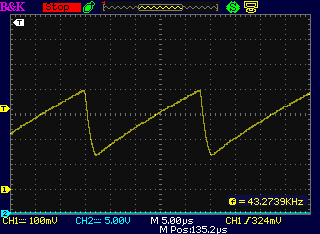
 Variable Frequency "CRM" Modulation
Trace1 - motor off (43KHz); Trace2 - motor running (27KHz)
(Osc. probe 10x, so actually ~3V ramp)
With the motor running, the slope of the oscillation ramp
was much shallower in the powered part of the modulation cycle,
representing the 2.2KHz rate. In the unpowered part, the 42.6KHz rate
applied, resulting in lowering the modulation frequency to under 30KHz,
variably depending on the control setting, and on whether the cycle was
terminating earlier on overcurrent or regular PWM setting shutoff.
(Trace 2)
This is the desired effect, providing up to about 40KHz when a lot of
torque (high current) is needed to get the motor started under high
static load, and a slower and slower rate at higher loads and higher
speeds (probably well down into the audible range) where high speed
switching causes unnecessary switching losses. As usual with CRM
"Current Ramp Modulation" it's hard to set a steady RPM on the unloaded
motor. It wants to stop or go up to max. But the outboard motor shows
that when it's running a load it gets easier to control.
Probably the maximum 42KHZ should be reduced a little,
maybe to 25, 30 or 35 KHz, and the minimum 2200 Hz down to maybe 1000
or 1500.
But these are just resistor or capacitor value "fine tuning"
adjustments.
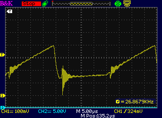
Energy Return Losses
Whatever one may think of the potential for losses owing
to the unusual energy return system with the series coil, it appears to
work, and it is a fact that the motor coils' return energy only passes
through one diode drop instead of two, potentially halving that cause
of energy loss.
Furthermore, in other controllers, the return energy pulse
is applied across the power supply voltage. When the voltage in the
spike is reduced to the power supply voltage (plus two diode drops), no
more energy is returned. The unipolar controller drains the motor coil
pulse down to zero volts (plus one diode drop) regardless of the power
supply voltage. I don't know the exact calculations or the coil pulse
figures to start from, but I figure one will get more energy from
draining a
pulse down to zero volts than down to 36 volts.
Running some hypothetical numbers... If the voltage
pulse from the coil is (or would be with no load) 180 volts and the
power supply is 36 volts, and the energy remaining in the coil is
proportional to the square of the voltage, then (180^2 - 36^2) / 180^2
= 96% of the energy would be returned, versus 100% for the unipolar. If
the coil pulse voltage would only have been 90 volts, (90^2 - 36^2 /
90^2 = only 84% of the energy would be returned. If the pulse voltage
would have been 360 volts no load, the loss is just one percent.
If the energy remaining was simply proportional to the
voltage (not squared), (180-36)/180 = 80% return, or for 90 volts,
(90-36)/90 = only 60%, or for 360 volts: (360-36) / 360 = 90%.
I suspect the energy must be proportional to the square,
and I suspect the voltage pulse potential is moderate to higher rather
than lower, but in the bipolar system there is some theoretical loss
involved however small, where the unipolar controller is theoretically
"lossless" in this regard except for the one diode drop voltage.
It will be exciting to see if there's any actual notable
improvement, but I haven't noticed anything so far. The fact that it's
not the very same motor as was tested previously (the one in the
Electric
Caik outboard) makes it hard to determine the source of small
differences, whether better or worse. They could quite easily be
mechanical.
Synchronous Rectification
After deciding I was finished, at least a couple of things
still bothered me a bit. One was electrical noise. But how much can
that be reduced in a unit switching high currents? Keep the runs short!
Another was the heat
in the powerline coil for energy recirculation. That may drop when I
make coils with heavier wire, probably using two of the iron powder
cores instead of one.
Even more was the heat in the energy recirculation diodes.
The Kelly controller manual said theirs used synchronous rectification,
where the mosfet is turned on when the body diode would be active,
substantially reducing the voltage drop - and hence waste energy and
heat. I had rejected out of hand the idea of putting mosfets in in
place of diodes because of the possibility of shoot-through currents.
But I had ended up using mosfets anyway because their body diodes were
both better and cheaper diodes than simple power diodes. (Huh?) And
they still got hot.
As I woke up on the morning of the 15th, an idea that was
vaguely forming in my subconscious jelled. These would be high-side
mosfets. If the floating gates of these "active diodes" were driven,
not as usual by transistors from some circuit that used logic to decide
when to turn them on and off, but by the coil drive itself, they could
hardly activate except at the exact moment the coil turned off -
exactly when they were needed. The operational aspects are as follows:
When the coil turns on, the coil signal is driven to ground. Since it's
going negative WRT the mosfet, even a big spike to the gate pin can't
turn the mosfet gate on. When the coil is on and the signal is at
ground, the floating gate charge capacitor charges, in a few
microseconds. While the coil is on, no other coils are switching since
just one coil is driven at a time. So there won't be any spikes that
could couple through and spuriously activate the gate/mosfet, except
when the coil is off anyway. As the coil is turned off, it spikes high.
This is where the body diode of the mosfet conducts to return the
coil's energy to the power buss. But the gate signal goes high through
its now charged capacitor, so the mosfet will turn on, reducing the
diode voltage drop at exactly the right moment, active for a few
microseconds. (A 3:1 voltage divider will be used since the power is
~36 volts and the maximum gate voltage of most mosfets is 20 volts.) A
resistor is sized to bleed off the charge of the floating gate
capacitor in a few microseconds - well before the coil would turn on
again. Slow turn-on of the mosfet is of no concern because it occurs as
the coil voltage is rising and before it goes positive. In fact, it may
contribute to faster turn-off/rise time of the coil, and actually draw
current momentarily from the supply for that. This is my only real
concern: a short region of linear operation as the coil voltage rises
toward the supply voltage. The mosfet gate's linear signal region in
the decay voltage doesn't matter because the coil by then has no
voltage across it. The same would apply to any "off" spikes that might
manage to partly (or fully) activate the gate from the other two phase
coils. And since the voltage is backward at the active time, the body
diode would still take the load if the mosfet is only partly on,
preventing even partial turn-ons from causing high power to be
dissipated inside the mosfet.
Thus, the synchronous rectification is gained and is
synced by the very signal being rectified, improving efficiency and
reducing heat, but with only the most miniscule possibility that any
shoot-through current could occur.
After I thought I had all this figured out, I realized
that the mosfet would turn on the whole time the source pin was pulled
low by the coil - much more than a transient shoot-through! It appeared
some sort of switch would be needed after all. And the circuit started
to look complicated - at least a couple of transistors and associated
components. Maybe I wouldn't bother for version one - just heat sink
the diodes well and get on with making the controllers.
At this point it occurred to me to put the 3 mosfets on a
copper bar as a fourth bar in the row of bars sticking out, and have
the transistors as well as the associated resistors and capacitors on
the circuit board. At this point I'd be really sure I'd need a bigger
circuit board than Eagle will let me make with the "cheap" license...
Except that there's only
about 6 connections to the rest of the circuit. What about making it a
separate board and run six wires between the "logic" and "power"
boards? The power board is mainly heavy current connections that should
use heavy wires anyway. And some of the big filter capacitors should go
on it too. So now the original board would need few changes. TaDah!
With only 6 connections between all the "brains" parts and
the high power components [Ground, Battery+, A, B & C gate drives,
and current sense], they could be plugged together with a 6-pin header
strip and socket. Then the power components could be swapped out for
repair without removing the control parts and control wiring. Then, if
the big filter capacitors were on the bottom of the power board and the
mosfets were on the top, the power board could be a lot smaller.
Perhaps the electrical noise could be kept from the logic section, and
I might even still get it all into those little extruded aluminum
boxes. Hmm, hmm!
In fact, the mosfets could just about as easily be screwed
to the copper bars (as they are anyway) and hard wired instead of
circuit board mounted, leaving only the smaller logic board, under 3" x
3". The only components not on this board would be the mosfets, the
filter capacitors, and the current sense "shunt" resistor... and the
synchronous rectification components.
The rectification might well have its own little circuit
board hanging off the feet of the "synchronous diodes"... which
(come to think of it) should be powered by the +12 volt logic supply
instead of the variable battery voltage. That would eliminate the
resistive voltage dividers and concerns about different battery
voltages causing different gate drive voltages. And if "version 1"
doesn't have synchronous rectification at first, it can easily be added
later. (To supply Vcc and Ground to the synchronous rectifier board,
the logic board connector will need 8 pins instead of 6.) But after a
couple of late evening doodling sessions, I came up with a fairly
simple single transistor circuit before retiring on the 17th, and I
designed the board the next day. Soon after that, I found a chip
designed for this very job, so it probably does it better so I'll
probably order some and change the design. (On the other hand, it's a
bit pricey at 5$ and hardly reduces the component count.)
As August starts, it looks like I'll be converting all my
motors immediately to the new 'BLDC4:3' configuration, which I'm sure
is better. That means I'll be making some unipolar controllers sooner
rather than later.
Variable
planetary gear transmission with Centrifugal clutch in Chevy Sprint
I'll start by discussing my largest concern with the system as built;
the biggest reason my confidence level it'll fly as built isn't really
very
high: I made the variable planetary gear system in 2012 thinking it
would run the car. The tests showed the idea worked great -- but only
once everything was in motion... how to get the car moving other than
by
placing it where it would almost start rolling by itself?
One possibility was a giant flywheel on the motor itself
so that one could rev it up and then tighten the control pulley
tensioner. The energy in the flywheel would start the car moving as the
motor slowed, even with no torque conversion at first. I goofed when I
tried that technique. I mounted a flywheel on the control/slip gear
instead, because that was much easier.
Only later did I realize that there it did nothing useful - the force
of slowing that pulley didn't transfer to the wheels, only to the rope
tensioner, making heat. The flywheel had to be on the
motor itself, and really I had no place or shaft to mount a flywheel on
the motor.
The other way would be to use a clutch. That would let the
whole gear train start into motion to activate the torque conversion so
the car would start moving under all conditions when the clutch was let
out. In 2013 I tried to make one that let a flat belt slip when the
clutch peddle was pressed, replacing the chain drive. But it was...
well, poorly designed and made. The slipping belt slipped off the
pulley sideways and it was probably too narrow for sufficient grip
anyway. A wider belt would get more grip from the same tension, but
there wasn't really room for a wide belt with its wide pulleys.
In 2014 I made the centrifugal clutch. I made it big, 9"
diameter and
3" wide for lower RPM. That's probably a great way to do it. And I
added some 3" "stand-off" blocks to move the motor over and effectively
widen the unit by 3" so everything would fit. (Yes, a 3" wide belt
would now fit, too.)
But still
I fear the RPM the clutch disk gets from the planetary gear will be too
low to start the car moving. The trouble is the RPM of the motor is
reduced by something like 1.8 to 1 in the planetary gear, so the clutch
will only be getting 1100 RPM. How much centrifugal force can that low
an RPM exert on the drum? I'd be more confident if the motor itself
would do a higher RPM, like at least 3000 instead of 2000 so the clutch
disk was doing 1650 RPM or better. If it looked like it almost worked,
I'd probably try to run the motor up towards that RPM anyway. (and
stand off to the side!) If magnets flew off the rotor, it'd be time to
make the new 4:3 configuration rotor with the slots to run the PP
strapping through. Then it'd be the new improved type, and surely good
for 3000 RPM too. Of course I'd want to do that eventually anyway, but
I was hoping to put it off until I tested the transmission and
hopefully either moved the car or found it needed changing. Also if
rotor magnets flew off, it'd be a good test of the solidity of the
outer wall of the rotor compartment.
Moving ahead... on the 31st I tried out the Kelly
controller. It spun the motor so fast so quickly that after just a few
spins, the rotor failed and I never did get to try anything else, so
the above rebuild and reconfigure will apply. The outer wall was
scuffed up, but held okay. I didn't get as far as attaching meters, so
don't know what RPM was reached - it could have been 3000, 3500 or
4000. The motor with the new attachment techniques should easily
withstand 3500 RPM and probably 4500 or more.
If I can't make it work even at 3500 motor RPM, I'll
probably have to reverse the
whole planetary gear configuration so that the RPM at the clutch is
increased by 1.8 to 1 instead of decreased, providing a good 3600 RPM
from 2000 RPM at the motor. That
would take much rebuilding. On the other hand (now that I think about
it), with the 4:1 chain reduction following, it would give a good
matched set of RPM.s: motor 0-2500, high RPM.s to 4500 to activate the
centrifugal clutch, and 0-1125 RPM to the wheels for around 0-100
Km/Hr. I have a funny feeling I'll have to change it, but I'll
certainly try it out as is first. Now it'll have to be with the new
motor configuration and new unipolar controller.
Now, on to the month's work.
On the 10th, after about 9 months of diversion, I finally
put the
transmission and motor into the Sprint... after a time out to wash
nearly four
years of accumulated pollen and moss off the car. It's hard to believe
it's been so long since I bought it thinking to make a quick electric
conversion of some sort with it. I guess the Mazda took its place for
that -- and also convinced me that getting rid of the inefficient
regular automotive transmission is essential for good results: lower
power requirement, less battery storage and longer driving range.
I got out the Kelly 24-36V,
0-300A BLDC motor controller that I purchased last fall, and
screwed it too under the hood - a temporary mounting. Of course now I
feel the 'standard' BLDC
motor and controller are obsolete. But I wasn't going to change over
what's (hopefully) ready to use at this point when it would delay
everything still more. Assuming I get the Kelly working and it
continued to do so without failing under heavy loads like my
controllers. There were lots of wires to connect and to get right so
as, hopefully,
not to have everything go up in smoke.
The next day I made up the three power wires to the motor.
For some reason this seemed to take hours, perhaps because I was busy
doing 3D printing for an order of 12VDC CAT sockets, plugs and wall
plates at the same time. (When I went to put the wires in the car, it
started to rain - a light sprinkle for the first time in a month. The
water on the house roof didn't get past the moss.)
The transmission having the planetary gear
variable torque converter with slipping
control pulley (tensioner not connected yet) and large, lower RPM
centrifugal clutch.
(Somehow I don't seem to have taken a picture while the motor was on
it.)
On the 12th I went to KellyController.com and, at last
downloading the manuals, started looking up how to connect and
configure everything. It looked like there would be a fair learning
curve.
Should I swap everything over to my new controller and make a new 4:3
rotor for the motor? Notwithstanding that I now view the 'standard'
BLDC motor and controller as a temporary arrangement I decided to
persevere. With luck the default settings will be acceptable... and, I
just might learn a few useful things about motor controller setups. But
studying the wiring diagram, it didn't look so bad - pretty similar to
mine, really.
The rotor position sensor connections to the motor are the
same as mine, except the controller supplies 5V instead of 12V. The
Hall sensors will work either way. (Optical sensors with the 3
LED.s in series would need a higher voltage to turn on.) In fact, in
spite of the 5 volt supply, the outputs were at 0 or 10 volts.
The
temperature sensor range is also 0-5V, but I didn't find what kind of
sensor is expected, and anyway, 5V isn't enough to run the AD590
temperature sensor as configured. Maybe just a potentiometer to fake
"temperature okay"? Finally I found "thermistor" in the J2 pin diagram
(the wire just says "temperature"), and on a search for that word in
the manual, under "Features" I found, very specifically: "Configurable motor over-temperature detection and
protection with the recommended thermistor KTY84-130." (A
specific thermistor only? So much for "configurable"!) But the wiring
diagram showed the temperature pin unconnected - yay! The wiring
diagram also only showed the "J2" plug and not "J1". It didn't need all
those wires to run? Yay again.
However, it started to look like I should make another
order with KellyController.com, for various "accessory" parts -
especially the ampmeter. (Why didn't I get that with the controller?)
If I was in it for 600$ or so already, another 100 or 200$ wouldn't
kill me. (To buy a laptop computer just to run the Microsoft Windows
based config program would definitely be annoying.) By the time I was
through at the web site, I was at 210$US, about 300-350$C when the
smoke settled.
While I waited for the controller parts, I hooked up a 12V
battery and started converting the light bulbs to LED.s. I ran out of
larger ones and had to order more. It's always a surprise how many
'bulbs' a car uses. I couldn't get the LED headlights to work. Not
until the 30th did it occur to me that the circuit in the Sprint was
backwards, putting +12V to the common pin and then grounding the low
and high beam pins to activate them. Of course reverse voltage doesn't
work for LED.s. I could reverse one set easily enough. Getting both low
and high beams without taking the dash and switches apart was going to
be difficult. Anyway, "high beam" seemed to be just turning all same
the LED.s on brighter than "low beam". Hmm... On August first I took
the relevant part of the dash apart.
The Kelly Controller Panel in the car
(Again no picture with the motor connected.)
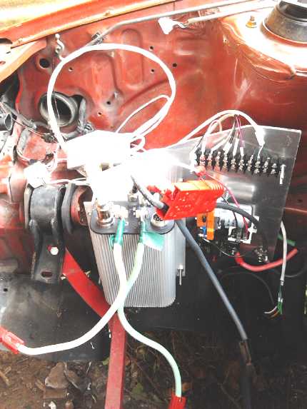 The parts having arrived, from the 23rd I picked away day
by day at mounting and wiring the controller. I made an aluminum back
plate
to fit where I wanted to mount it under the hood, and then put the
components onto it one by one. I realized first that the power relay
was turned on by the same switch that turned on the 36 volts to the
controller, but that the ignition key had a 12 volt coil. I couldn't
use the 12 volt relay, and I couldn't supply 36 volts from the ignition
key. So I ended up first buying a 200 amp contactor relay with a 36
volt coil (in the Kelly order), and then adding a small 12 volt relay
to turn on the 36 volts when the car key was turned on, for the
contactor.
The parts having arrived, from the 23rd I picked away day
by day at mounting and wiring the controller. I made an aluminum back
plate
to fit where I wanted to mount it under the hood, and then put the
components onto it one by one. I realized first that the power relay
was turned on by the same switch that turned on the 36 volts to the
controller, but that the ignition key had a 12 volt coil. I couldn't
use the 12 volt relay, and I couldn't supply 36 volts from the ignition
key. So I ended up first buying a 200 amp contactor relay with a 36
volt coil (in the Kelly order), and then adding a small 12 volt relay
to turn on the 36 volts when the car key was turned on, for the
contactor.
I got finished the wiring and put 3 batteries into the
back of the car on the 30th. Double checking that all the wiring seemed
to make sense I tried the system on the 31st. There was a problem with
the Kelly hand control. The motor controller LED blinked a pattern
indicating the throttle was shorted. Really, it was just a very good
potentiomenter that went right to zero. I tried turning it half way up
before turning the power on, and then it complained about that with a
different blinking pattern. I tried disconnecting the hall sensor
cable, and it gave a another complaint pattern, followed by the first
one, alternating. I must admit the trouble codes, combined with the
manual, saved a lot of trouble tracking down the problem - it's a good
reason for computer overcontrol of the controller. I soldered in a 75
ohm resistor in the ground leg of the throttle pot., and finally got a
green light. When I turned it up even slightly, the motor spun! In
fact, it spun up really fast with the slightest turn of the pot. It
didn't always seem to like going backward, but when it did, it spun up
just as fast. So the hall sensors and motor phases all matched, with
the same connections as my controllers. (Wow!) After just a few spins
there was a "clunk" and the motor was seized. I didn't even get to
checking out the Kelly controller features, much less to installing the
torque converter tensioning rope and trying out the transmission.
When I got the motor apart,
all 12 magnets complete with
their polypropylene-epoxy strapping had flown loose from the rotor,
spread out, and jammed against the outside wall, all the way around! So
that was that for that! Maybe I should have tried 24 volts at first
instead of 36. How fast did it go? I hadn't got as far as connecting a
meter to check it. I've run that motor at maybe 2200-2400 RPM at least
a couple of times with loads, with no problems. So I'll guess it was
well over 3000 - probably over 3500 or 4000 RPM. Furthermore, it seems
this rotor had the "cold galvanizing compound" zinc anti-rust primer on
the rotor, and red (urethane?) spray paint on that. The zinc especially
has a weak bond, as I found out with the first Electric Caik motor.
This motor was made before that.
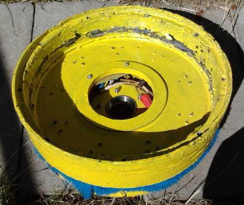
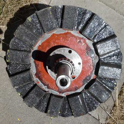 The motor, somewhat gouged, and the rotor,
looking almost normal but for the paint ending where the magnets used
to sit.
The motor, somewhat gouged, and the rotor,
looking almost normal but for the paint ending where the magnets used
to sit.
Rotor from the top (Top bearing still on shaft)
Only magnetism now holds the 'sprung' magnet assembly to the rotor.
So now I'll rebuild the rotor with all my latest magnet
attachment techniques on bare steel, and it should be good for much
higher RPM.s. It reminds me of someone who once talked about an
alternator or starter motor for a particular model car, which was
notorious for failing - the armature wiring would fly apart. After
repairing a couple and then re-doing them again, he changed the "glue"
in the armature - I forget what, from motor varnish to epoxy or
something. They never failed again, and he soon became known, not just
locally, as "the guy to go to" to get them fixed. They were the same
motors. Technique was everything.
As long as I'm rebuilding it, I will of course do it in
the new 'BLDC4:3' configuration: magnets NSNSNSNSNSNS instead of
NNSSNNSSNNSS, and with an exact placement magnet placing jig similar to
the one I made for the Electric Caik. It'll want the new unipolar
controller, so after all that expense and installing, the Kelly (which
seemed to work fine except for getting any fine control over the motor
speed/power) will be out.
Sprint Batteries and Battery Wiring Considerations
On the 13th I bought 4m of #6 AWG 4-wire "cab tire" (very
tough cable with a thick rubber jacket), removed the gas tank from the
Sprint (a long put off job) and ran the cable from the back to the
front under the car, intending to put the batteries at the back. I'll
double the wires as two pairs, which makes them the equivalent of AWG
#3.
The gas tank weighed 25 pounds, not counting the 5 liters
of gas I recovered. (2011 gas - ugh!) That makes 275 pounds of gas
stuff that's been removed from the 1710(? 'curb weight' IIRC) pound
car, making it around
1435. Then about 85 have been added of electrical transmission and
motor, and the fat 10 pound battery cable makes 95. Then there's the
batteries...
Since the voltage is only 36 volts, it seemed to me it
should have over 300 amp-hours, to have at least 10 KWH of energy and
plenty of current drive for the high amps of the motor. I still only
have 7 KWH available in NiMH (by stripping them from the Mazda),
despite all the cells I've bought over several years. There are 240 AH
golf cart batteries weighing about 65 pounds, 7-1/8" x 10-1/4" profile,
for about 150$ plus taxes each. So six of them for around 1000$. It
looked like they would just fit in the spare tire hole. I like the size
and the price, and they would weigh under 400 pounds. But 240 AH would
still be a little light on energy storage and on current drive. They
could be doubled, but then it would be twice the price and weight, and
they certainly wouldn't fit in easily.
It seems the next size up is 380 AH golf cart batteries -
60%
more energy - for about 350$. Obviously that's more cost per amp-hour,
over 2000$ total -- more costly than doubling up the 240 AH ones!
I can't say I like that very much. Well, I chose to use just 36 volts,
and that obviously meant using high amps and high amp-hour cells. 380
AH at 36 volts is 13.7 KWH and 600+ pounds, perhaps 1/2 of a "typical"
lead-acid EV battery storage and weight. It should provide a lot of
driving range in this small vehicle with an 'ultra efficient' drive
system, and the high currents should impose relatively low stress on
these huge batteries.
It works out to 150 $/KWH instead of 105$ for the
240 AH ones. But the batteries are supposed to be good for around 600
cycles. Compare that to NiMH dry cells or lithium at 1000 $/KWH. That's
about 4000 cycles for the same price, albeit with some fuss in changing
them 6-1/2 times more often, having substantially more weight in the
car, lower voltages under load... and then probably not getting the
rated performance and life from them anyway.
They weigh around 100+ pounds and are considerably
larger than
the 240 AH ones, 7-1/8" x ~12" (and very tall - 16"?). They wouldn't
fit in the spare tire well, but
they would still fit in a single row across the back, just inside the
tailgate. The loss of luggage space wouldn't be severe (partly because
the back seat folds down when more is needed).
A friend, Tom Sawyer, pointed out that putting them at the
very back - which seemed so convenient - would put a lot of weight
(probably over 600 pounds) behind the rear axle, and said I should put
them at the rear seat
position, between front and rear, for balance. We both stood on the
rear bumper (together 365
pounds). It wasn't bottomed out, but it certainly went down a long way.
Thanks Tom for wrecking a great plan!
Maybe I should put 350 or 400 AH of NiMH together as one
12V battery and just buy four of the 380 AH golf cart batteries? That
would at least save some weight and money, but it wouldn't
solve the problem. (8 sets of 50AH, 12V NiMH @20 pounds for 400AH would
be 160 pounds instead of 200+. With the other 400+ that's still too
much weight at the back.)
Next plan: Two of these giant batteries would fit under
the hood. (Three might be managed, but not at all easily.) That would
leave only four to put at the back -- or two plus a big stack of NiMH.s.
Or... the original plan was for 300 AH. I seem to be
upping that in my mind to match the golf cart batteries' 380. I could
just make up two 12 V, 300 AH NiMH sections from my existing stock, and
only add two of the big golf cart batteries for the third section. I
already have 300 AH of soldered batteries in boxes and 240 of 'giant
flashlight tube' pipes. Another 6 pipes (60 AH) would get that up to
300. It leaves me a few cells as replacements for any that may be bad.
That would also be only 250 pounds (NiMH) in the back instead of 400
(PbPb) - and more cargo space - and 200 pounds (PbPb) under the hood,
total 450 pounds. And it's the lowest immediate cost. The extra 80
amp-hours of the front PbPb pair can be
the lowest 12 volts to run the lights and all. That seems very
agreeable, so it's the plan.
Again using separate chargers for each 12 volt section
allows use of non-identical batteries. As they age the golf cart
batteries can be replaced as a pair (or perhaps even singly by using
two 6 volt chargers?), reducing
the sudden major 'fueling' cost. And since the NiMH.s seem mostly to
weaken rather than to fail, a few more cells here and there can simply
be added to increase
or if necessary maintain the range, probably for quite a long time.
So I'll leave some room
for a few more amp-hours of NiMH in the back for additional range, and
of course there'd be room to change the ones at the front to NiMH or
lithium if I want to spring 3000$ some time.
For testing I
just put 3 size 27 RV batteries in the
back on a sheet of plywood, nothing up front. While it's good to have
an arrangement worked out, permanent battery considerations
are academic until the car is otherwise roadworthy.
Electric
Caik/Honda75 Outboard test - fishing trip
Well, I finally went on my fishing trip on the 23rd. From
the start things went wrong - I forgot the bait, a net or gaff, and a
club. I was told it wasn't rough, but the waves increased as I fished.
I was jigging for cod or halibut, but they probably weren't interested
in the plastic squids. Then I tried trolling with a salmon lure.
Evidently I was drifting sideways as much as going forward, because the
line tangled in the propeller. I could see that if I leaned far enough
over the stern to try and untangle it, the waves would come over the
transom. The tackle seemed to be still attached, so I rowed back to the
launch ramp. I wasn't venturing too, with the chance of
some failure always in mind. Back at the dock I untangled the line and
reeled it in. I saved my 1970.s flasher, hook et al!
Then I tried to motor over to the launch ramp to trailer
the boat, and found the motor was seized! And it was hot. That is, the
shaft and bearings were hot, and the coil clamping bolts were hot. (The
new model has nylon coil bolts, not subject to magnetic induction, so
that last won't happen in new ones.)
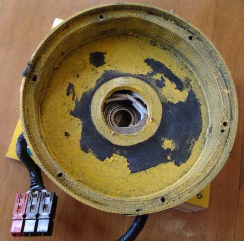 The top (stator end) of the motor was pressed
up by the coupler at the bottom of the shaft until
The top (stator end) of the motor was pressed
up by the coupler at the bottom of the shaft until
everything got hot, the case deformed, and the rotor magnets started
rubbing on the stator
compartment wall until they jammed against it.
I found the culprit: The "joy" coupling connecting the
motor shaft to
the outboard drive shaft had forced its way down the shaft, pressing
the motor shaft up and the outboard drive shaft down. The latter made
for gear noise in the outboard, which I could hear from the start of
the trip. Perhaps I should have paid some attention to it! As it pushed
the motor shaft up, it finally - or eventually - deformed the
polypropylene-epoxy end cover of the motor until the rotor rubbed on
the stator wall and finally seized against it. (I should have paid
attention to the slight rubbing sound I could hear before the trip,
too!) Reinforcing the actual rubbing, a thin gap setting makes the
motors run rough and doubtless generate excess heat.
The set screw in the joy coupling pressed against the
shaft key rather than the shaft itself. That may be good for holding
the shaft key in place, but it seems like - and has now been proven to
be - a poor arrangement for holding the coupling itself in place. I'll
drill another hole and add another set screw to grip against the shaft.
(Both top and bottom coupling halves.) The better way to prevent a
shaft key from sliding out, if the slot is long enough that it can, is
to take a hammer and cold chisel or something and put a big dent at the
end (or both ends) to prevent the key from sliding.
And when I do the new Electric Caik body molds (with the
slightly enlarged rotor & coil circle diameter) I'll look for ways
to thicken and strengthen the center area where the bearings attach.
 Noting that the needle
bearings seem to have a lot of
friction when I install them new, I've mentioned that I thought they
would loosen up over time and as the excess of grease came out. Here is
the lower bearing from the outboard, which has now had a few hours on
it, oozing green grease. But it's still somewhat stiff. The top bearing
shows no grease, but it now turns pretty freely.
Noting that the needle
bearings seem to have a lot of
friction when I install them new, I've mentioned that I thought they
would loosen up over time and as the excess of grease came out. Here is
the lower bearing from the outboard, which has now had a few hours on
it, oozing green grease. But it's still somewhat stiff. The top bearing
shows no grease, but it now turns pretty freely.
Copenhagen
Wheel bicycle motor system - & Battery Issue Comments
Someone sent me a link to an interesting and well hyped-up
bicycle "pedal assist" motor system:
https://superpedestrian.com/
(Copenhagen, Denmark, has more bicycles per capita in daily use than
anywhere
else in the world.) Evidently everything comes in one kit. There was a
video, from 2013. The next video was a 'production update' from a year
later, November 2014. It reminded me of the trend in my projects... the
prototype
product being proved, then improved and improved, with some really
exciting sounding
stuff, but nothing getting produced. Here it was claimed they'd be
available 2nd quarter of 2015. But I didn't see a "Purchase" option on
the web site. I hope they get there.
A down side in the specs was that it was only 350 watts.
E-bike affictionados around here use more powerful motors as any visit
to the monthly VEVA meeting will disclose. [usually 1st Wednesday
evening of each month. See www.VEVA.bc.ca
- VEVA Islands] I've ridden a couple. A couple were more like
clandestine motorcycles.
Of particular interest to me was that
the specs said the lithium batteries were only good for 1000 cycles -
much less than the several thousands of cycles claimed for many.
Nickel-metal hydride dry cells were derated without comment from 1000
to only 500 cycles on the all-battery.com website. Although heavy and
not well suited to bicycles, lead-acid golf cart batteries are rated
for over 500 or 600 cycles, and are far cheaper per kilowatt hour.
GM EV1
Brochure
Tom Sawyer said he had seen a 1998 brochure for the
original GM EV1 for sale on
e-bay. I bought it. I scanned it and I reprint it here fairly large
because the writing isn't legible if it's further reduced. It contains
some fine humbuggery such as why you could only lease one and not buy
it: in one place, 'because they'd use better electric motors in two
years, so the car would then be worthless' and then (not to be too
consistent, bottom center of side 2) 'because they were expensive'.
(and who set the high price?) When did any car company refuse to sell a
gas car for either of those reasons? And when did a new model ever make
the old model suddenly depreciate to zero? This was one of several
insidious things presented in the brochure designed to turn off
prospective customers or clients - and to excuse the fact that you
couldn't buy one. In fact, among all the features touted to appease the
California authorities, the majority seem to be presented in the worst
light instead of the best to deter interest. For example, any
advertiser worth his salt would have said at the top left of side 1,
something more like "Futuristic styling and aerodynamic design maximize
the battery powered EV1's driving range." (In fact, even today only
Tesla model EV.s have surpassed the EV1's driving range of 160 miles
(255Km).)
Aside from a few later estimates from those at the
suppressed
company, the lowest being "200 $/KWH in mass production", we never did
find out what the price would be
for large flooded nickel-metal hydride batteries in mass production,
and as long as they're suppressed, people must settle for lead-acid
(which should have been out of production for years by now) or pay - at
least - double
or triple that figure for lithium types.
Aside from being electric, the EV1 first introduced some
novel features now common including larger wheels (15" IIRC) holding
tires with narrow sidewalls. If you haven't seen it yet, do watch the
documentary Who Killed the Electric Car? about the
manufacture, leasing only, and suppression of the EV1
and most other electric cars and their NiMH batteries by every car
company, in the late 1990.s in California, and their final destruction
about 2002. (It was on youtube last time
I looked.)
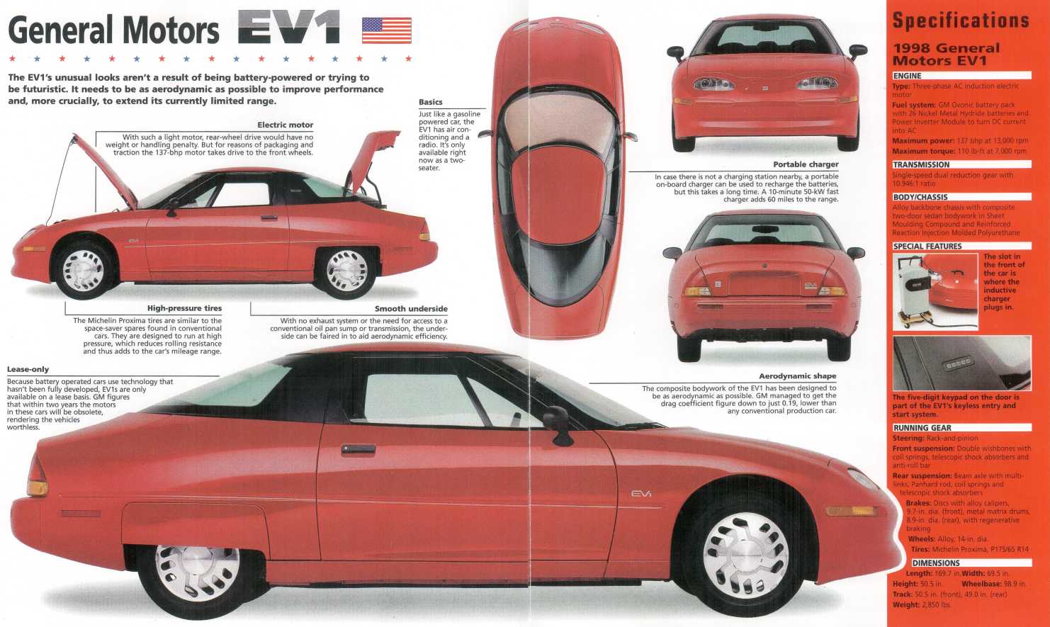
Side 1 of the brochure
Side 2
http://www.TurquoiseEnergy.com
Victoria BC Canada