Turquoise
Energy Ltd. News #91
covering August 2015 (posted September 2nd)
Victoria BC
by Craig Carmichael
www.TurquoiseEnergy.com
= www.ElectricCaik.com
= www.ElectricHubcap.com
= www.ElectricWeel.com
Highlights: TWO Improved Axial flux
Switched Reluctance Motors: "AFSRM" or "ARM" and "Transverse Flux" Motor
(Building ARM is in
progress - see Month in Brief, Electric Transport topic)
Month In Brief
(Project Summaries)
- Plan that got changed - ARM Motor - An even better(?) SR motor
layout! - Mounting a Motor for a Car Wheel Drive - Solar Water Heater -
Peltier Cooler Voltage Tests - Battery DES Chemicals arrive
In Passing
(Miscellaneous topics, editorial comments & opinionated rants)
* Solar PV Power coming of age - Comet
67"P"
for
"Perspective"
-
Putin/leadership/spread
of power - More Collapse Warnings and Signs
Add to the Chorus - chem trails seriously interfere
with solar collection - Fuchsia Berry Pie - Funnies(?)
- In Depth Project Reports -
Electric Transport - Electric Hubcap Motor Systems
* ARM motor project
* "Transverse flux" SR motor idea & project
* Making an offset motor with belt drive "Electric Hubcap" Plug-in
Hybrid EV Installation: wheel end parts.
* Sprint: work stopped again owing to competing attractions. (ie, by
very promising looking new motors, again!)
Other "Green"
Electric Equipment Projects
* Solar Hot Water Heater
* Peltier Module/Thermoelectric Cooler Experiment: supply
voltage versus attained cooling.
Electricity Generation (no reports
[but see Solar Water Heater in Other Green Projects,
and Solar PV coming of Age in In Passing])
Electricity Storage - Turquoise Battery
Project (NiMn, NiNi), etc. (No reports)
No Project Reports on: Magnet
motor,
Lambda ray collector, evacuated tube heat radiators, CNC
gardening/farming machine, Electric Weel, battery making, aquaponics.
August in Brief
The First Plan...
On the 2nd I prioritized what I thought were my main project objectives:
1. Make a 12 magnet placement jig for Electric Hubcap rotors, similar
to the one I did for the 8 magnet Electric Caik rotors.
2. Mill the rotor (same one) slots for the new style magnet strapping.
3. Attach the magnets. While the epoxy is wet, patch up the gouged
rotor wall in the motor.
4. Reassemble the motor and reinstall it in the Sprint.
5. Try it out with the Kelly controller to see if it works. (I'm really
still not quite sure whether it will or whether all the propulsive
forces cancel
out.)
PATH A: Kelly controller works
6. Connect the torque converter control pulley linkage to the shift
stick.
7. Try to get Sprint moving.
PATH B: It doesn't work, or after path A is done
6.(8.) Edit the unipolar controller circuit board and finish it up.
7.(9.) Print the artwork and Etch the board.
8.(10.) solder on the components.
9.(11.) put together the controller.
10.(13.) Test the controller on the Caik and Hubcap 4:3 motors.
11. Go to path A if it wasn't done before.
There was more of course, but I figured that would be at least a full
plate for August. I did have a little holiday coming up!
But the seemingly straightforward plan immediately got off
track. I started (ignoring
the task numbers) by trying to get the LED
headlights working in the Sprint, since I already had half the dash
apart. Something weird was happening and I soon wished I had left the
headlights alone. Then I pulled the shifter cable out to see how I
might set it up. Later I
thought to cut one end off the cable so it fit the same inside at the
shift stick but had a fresh cut end to work with under the hood. And it
let me slip off the offending pipe that diverted the cable in the wrong
direction at the firewall.
On the 7th I wired the headlight switch and the right
headlight back to the original wiring, and put a
halogen headlight back
in the right side. The only way it would come on was with "momentary
flash" - not with regular low or high beam settings. Apparently they
hadn't been working in the first place. (Didn't the dealer drive it to
my place with the headlights on? Who can remember so far back.) There
had to be a break between the light switch and the high-low beam switch
- but there should be nothing but a wire and maybe a connector between
them. Would I have had to deal with that somehow regardless? I decided
to give that a rest and bought some copper pipe for a hot water solar
collector.
Then the motor plans started to morf.
The ARM Motor
I rather suddenly determined on a good axial
flux switched reluctance motor ("AFSRM") design on the 9th. It should
be easier to make than my supermagnet motors, and if it's really
better, how much farther do I want to go developing the BLDC type I'll
probably never make any more of? Especially if the high RPM capability
of SRM.s eliminates the whole need for a variable torque converter
transmission for EV.s?
The new design still uses my same
toroidal coils, as "cup electromagnets" with a steel outer ring, to
attract
matching "overlapping ring" rotor poles. If the very tight tolerances
and narrow flux gap can be reliably accommodated, it promises to be a
winner, with much more torque than what I was thinking of previously
and (I expect) less torque ripple than other 3-phase SR motors. With a
'solid' steel rotor having no magnets or wires, very high RPM.s can be
easily and safely attained, and since power = torque * speed, small
higher power motors become more feasible. Outboard motor conversions
will work better with high RPM motors, and the external wheel drive to
"hybridize" cars, with just a fixed gear ratio,
gets much easier.
With no supermagnets and minimal copper they'd be
intrinsically the cheapest
of motors, and with waterjet cut steel parts they'll be easy to make
and to assemble. I can see motor kits being much more practical to put
together, more 'professional' in form and parts, and easier to assemble
than the BLDC/supermagnet type.
The inherently more reliable unipolar motor controller
I've been doing for some
months now is (somewhat fortuitously) the right type for both the
"BLDC4:3" motors and for the reluctance type.
The new concept had been
vaguely brewing in my mind. It was loosely based on an odd
feature of a 'theoretical' design AFSRM in one of the research
papers, a four phase motor with 16 coils and 20 rotor poles. So what
made that seemingly "written in stone" 3 to 2 configuration
necessary in three-phase motors? I had just successfully run the BLDC
magnet motor
having 4 magnet poles per 3 coils instead of two. For SRM.s were there
not multiple possibilities? On the 9th I decided to try out some
layouts for visualization.
Since I had "donut" coils with a metal ring around them,
forming something like "cup magnets" (here, "cup electromagnets"), then
instead of straight lines, I could have rings on the rotor that matched
the narrow flux gap rings of the coils. As the steel ring came near
alignment
with the coil flux ring, they would be strongly attracted to line up.
The reluctance would change rapidly over a short angle of turning which
creates strong torque, but it would be less abrupt than with straight
lines. Good torque but with less torque ripple would doubtless also
produce less noise, which is listed as a complaint against switched
reluctance motors. If after a
rotor ring(s) lined up with the phase A coil(s) another ring was in
position to start lining up with coils B (or C), the process could be
repeated, and then repeated again with coils C (or B). After that, the
second rotor coil would be in position for phase A again.
What was needed was not two rings per three coils, because
each time, the next ring would be too far from the next coil for good
torque. Instead a number of rings had to be found such that the next
ring for each phase was positioned just about right for high torque
just as the
previous phase shut off.
Four rings per three phases
When ring 1 reached coil A as shown, A would shut off and C would turn
on,
but ring 4 is too far from coil C for strong torque at first.
The same situation will apply for each change of phase.
(Coil A is shown with the outer steel ring. The rest are just
the cores.)
2, 4 or 5 rings per three coils weren't enough to get the
next ring
very close to the next coil. 3, 6 and 9 are even multiples of three so
the
rings all align with the coils at once instead of in a 3-phase
sequence. 7, while it might have been close to a good distance, had
two rings almost equi-distant on each side of the coil at turn-on time,
which
would cause nearly as much reverse torque as forward. 10 filled
in too much space to make a rather solid rotor instead of distinct
rings. But 8 seemed
to work out. As seemed intuitive afterward, the ratio at the ring
centers was about 1/3 metal ring to 2/3 air gap between... seemingly
just
right for
three phase operation.
 The
energization sequence (clockwise rotation of the rings/rotor) pulls
ring 1 to coil A as shown,
then 4 to B, then 7 to C. Then 2 pulls to A, 5 to B and 8 to C. Then 3,
6, 1
etc. By the time
ring 1 is back at coil A, there have been 8 electrical cycles for one
electrical rotation. And since there are six coils, two for each phase,
there are 16
cycles for each physical rotation. So instead of 6 changes of active
phase through broad, mostly low torque areas, it's 48 total coil
activations in the sequence, each for a short distance through the
highest
torque zones.
The
energization sequence (clockwise rotation of the rings/rotor) pulls
ring 1 to coil A as shown,
then 4 to B, then 7 to C. Then 2 pulls to A, 5 to B and 8 to C. Then 3,
6, 1
etc. By the time
ring 1 is back at coil A, there have been 8 electrical cycles for one
electrical rotation. And since there are six coils, two for each phase,
there are 16
cycles for each physical rotation. So instead of 6 changes of active
phase through broad, mostly low torque areas, it's 48 total coil
activations in the sequence, each for a short distance through the
highest
torque zones.
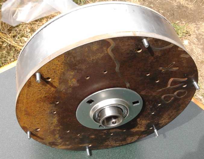
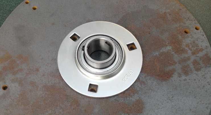
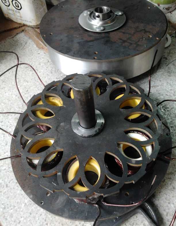 ARM motor with overlapping rings rotor.
Bearings including thrust bearing are installed.
ARM motor with overlapping rings rotor.
Bearings including thrust bearing are installed.
Coils await outer rings and attachment to the plate, and then it needs
optical interrupter
rotor position sensors mounted. Then wiring, assembly and testing. oh,
and painting!
The outer flats are optical interrupters for sensing.
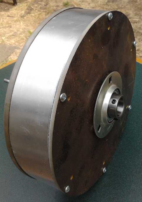 Test assembly of ARM motor case.
Far from my original design of AFSRM motor that would
probably run okay but with low torque and power, here was something to
challenge the state of the art - and drive a car with! If it could
provide start-up torque with a drive ratio for a single pair of toothed
pulleys, like 3, 4 or 5 to 1 (making it 3000-5000 RPM at 100 Km/Hr for
typical 13" wheels), that would be ideal. (If the ratio gets much
higher, there'd probably have to be a double reduction configuration
with two belts and extra pulleys.)
Then, Another New Motor Design
While I was on holiday, someone sent me a link to a new
"transverse flux" BLDC motor layout. It made some strong claims, and it
looked like it could be turned into a potentially superior reluctance
motor layout. The most interesting feature is that each phase has just
one coil, with the wire
wrapped all the way around the entire stator. Without having to wrap
a wire around each separate magnetic "tooth", the number and density of
the teeth can be greatly increased. More points of magnetic force could
greatly increase the potential
torque per area and per volume.
I would make a radial flux type of layout with the stator
ouside the rotor, and with narrow
"horseshoe magnet" teeth. With no coils overhanging the sides, even
with the three phases having to be
separate and side by side they are thin, and the motor
can
be thinner than my axial flux BLDC "pancake" motors. If the
"horseshoes" were a left and a right leg each from a mild steel plate
3/16" thick, with another piece of 3/16" thick plate between for the
'center' of the horseshoe (and a space to run the wire), that's
9/16", times 3 phases is 27/16", for a motor that could be as little as
2" thick. If the torque per area is effectively increased and a smaller
diameter rotor can have similar torque, a whole motor of a given torque
and power becomes substantially more compact. Cheaper. Lighter. Simpler
to make.
When this splendid info came the waterjet parts were
already cut. It seemed too late to simply cancel the "ARM" design, so
I've continued building it. I'll have two distinct models to compare.
Mounting a Motor for a Car Wheel Drive
 The troubles with mounting a motor directly on or in a car wheel are
(a) with no transmission it needs excessively high torque and (b) the
unsprung weight of this heavier motor interferes with 'handling', the
ability of the wheels to bounce up and down to drive over bumps and
dips smoothly. A few months ago I thought up an idea for mounting a
motor beside a rear wheel (behind it or ahead) with a belt drive, which
solves both problems without adding much friction. (Flat belt drives
are 99% efficient and toothed ones must be pretty close.) This month it
dawned on me what actual pieces to use to implement such a system, and
as I had them all I put them on the car to illustrate.
The troubles with mounting a motor directly on or in a car wheel are
(a) with no transmission it needs excessively high torque and (b) the
unsprung weight of this heavier motor interferes with 'handling', the
ability of the wheels to bounce up and down to drive over bumps and
dips smoothly. A few months ago I thought up an idea for mounting a
motor beside a rear wheel (behind it or ahead) with a belt drive, which
solves both problems without adding much friction. (Flat belt drives
are 99% efficient and toothed ones must be pretty close.) This month it
dawned on me what actual pieces to use to implement such a system, and
as I had them all I put them on the car to illustrate.
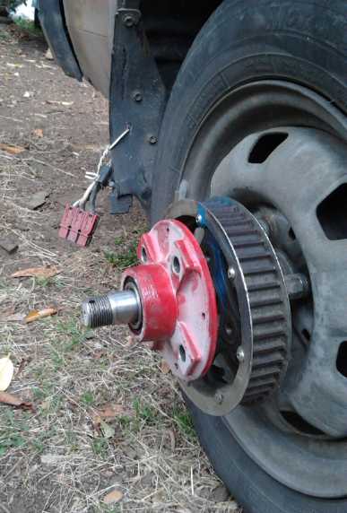
From the picture, visualize a sturdy bar with "belt guard"
edges, going straight back from the red hub to a pancake motor mounted
on the bar behind the wheel, with its axle sticking through to a
smaller toothed belt pulley. Since the bar is attached to the wheel
(hub) and the motor to the bar, the belt will maintain its normal
tension as the wheel bounces around with road bumps. The rear end of
the bar is attached to the car body/frame to hold it horizontal, but
with enough play to accomodate small movements as the wheel bounces.
Now it needs a high RPM 'pancake' reluctance motor having
the torque to turn the wheel with some fixed 'gear ratio' and the power
to run the car on the road.
See the detailed project writeup for more details.
Solar Hot Water Heater
On the 8th I thought again about the solar hot water (TE
News #88). In a house where people are living, solar hot water is the
best way to
reduce the electricity bill, heating much more water than solar PV
electric for a given panel size. A 4' x 8' (32 sq.ft.) panel is typical
for a minimal system. With all the plumbing involved it's not really
practical to bother with anything much smaller. Two panels is better
for a
family.
I had a copper tank (saved for many years now) for the
preheated
water. I decided to put a 'proper' copper collector
panel together, similar to the one I made in 1979.
Since copper pipe is rather costly I went to Ellice Recycling to see
what they had. I wanted 2-1/2' pipes, but at 5$/pound, it really wasn't
much cheaper than new pipes, and because they were odd lengths that had
to be cut with various leftover waste, they were actually more. I
spent a fair bit of money there before I realized this. I had a few
thin aluminum fins that clipped
onto 1/2" copper pipe and will buy more at Emco, to paint black and
form the
collection surface. They're 2' long by 4.75" wide. Since they're for
1/2" copper pipes, I'll still have to make something to extend the
collection surface of the 1" top and bottom pipes.
The pipes weren't cheap. I bought them in dribs and drabs, but
it was probably over 200$ for the collector alone.
Now I remember why alternatives to copper are ardently sought. But it's
the best for a collector (and perhaps woodstove connected) system that
might get quite hot.
An opposite problem is cold - freezing of pipes. Copper is
prone to splitting or joints pushing apart as the water freezes. I'll
circulate house water
through the collector and into the tank to keep the plumbing simple.
There will of course be valves but it's a pain to drain the collector,
high up on the roof with valves in the unfinished attic, for the
winter. I keep thinking a small water heating element in the
collector's
lower header
pipe, with a thermostat set just above freezing, would cause the water
to circulate to the tank and prevent everything from freezing. But
where does one find such a heater?
On the 28th I drilled thirty 5/8" holes in one of the
twelve foot
long 1"
pipes to silver solder three foot long 1/2" riser pipes to, then I cut
it at 8'. The fins above and below will bring it out to fill the almost
4' x 8' frame. A 4' x 8' piece of clear plastic (lexan?) would
cover the top with a bit of overhang. I tried to fit the pipes and they
didn't go in the holes easily. But if they weren't a close fit, they
couldn't be sliver soldered. I wished I had had something other than a
twist drill, which doesn't make very exact holes in thinner material
like pipe walls. Then I tried to solder in a pipe. While the silver
solder melted off the wire and beaded up near the joint, I couldn't
seem to get the
copper hot enough for it to flow with the propane swirljet torch. Of
course, there's a big copper pipe carrying off the heat, and the slower
the heat, the more it spreads out without getting the heated point up
to the required temperature. Next try will be with the scary old
naphtha gas torch someone gave me. It really puts out heat.
Peltier Module Cooler Voltage Tests
The Peltier cooler hadn't performed well when I went
camping. When I bought it to "reverse engineer" I had never intended to
use it. I had lost the aluminum heat transfer block and hadn't
reassembled it so well. After all this time, I thought to hook it up to
the the lab power supply and test out my ideas of better
performance at lower voltages. (I'd rather have Peltiers with 160-210
thermocouples to run at 12 volts, but except at very high price they
unbiquitously have 127 themocouples, which puts them in an operating
area that cools but has poor efficiency.)
Also, my complaints about their short life expectancy
(fine for occasional camping use, but not for continual home operation)
might be alleviated if they weren't being run so hard. That would make
a big difference in their practicality for appliances - heat pumps and
refrigerators.
I found it worked best at 9 or 10 volts. The temperatures got coolest,
and using much less power than at 12 to 14 volts. 9 volts got it
coldest, with half the power of 12 volts. Just as I suspected! (See
detailed project report for figures.) But I should try it all on the
Superinsulated Thermoelectric 12 volt Fridge, which is working well to
start with, and maybe try the large 14 amp Peltier module, run at lower
voltage and power. It might just cool the whole fridge better with the
same or less power.
Battery Making - DES ingredients arrive
When I returned from camping trip, my order for choline
chloride and ethylene glycol had been delivered, theoretically allowing
me to try making some "Ethaline" DES electrolyte. Then again, I need to
find time to check out the directions and do it. One can only tackle so
many things at a time, and I definitely have less energy than when I
was younger.
In Passing
(Miscellaneous topics, editorial comments & opinionated rants)
Solar Photovoltaic (Solar PV) Power Coming of Age
The price for smaller solar panels is over 2$/watt, but
the price for "full size" (about 1m x 1.6m) panels of 200-300 watts has
dropped to an
amazing 1$/watt even in shrinking Canadian dollars. If I went into a
glass shop and asked for a piece of tempered glass that size with an
aluminum frame, I'm sure it would cost more - without a solar
collector and wiring glued to the glass!
And the capacity of the panels (and so presumably the
conversion efficiency) has been creeping up, from a typical 200 watts
to 250 or better. This month I bought a 260 watt panel for 263$
(admittedly that's the wholesale price), to put
on the east sloping roof for more morning power. I'll then have
coverage pretty much from sunup until sundown.
But I seem to have missed making a contribution with my
nanocrystalline titanium dioxide borosilicate glaze frit, which was to
be sprinkled on solar panel cover glass and melted in like little
sidewalk pebbles. That would reduce reflections, difract the light
inward, and panels would pick up more ambient and low angle light when
full sun isn't coming straight on, for a higher daily total output.
In 2010 new solar installations became cheaper than new
nuclear plants. Solar has continued to cheapen and nuclear to rise in
cost even without considering serious environmental costs such as the
Chernobyl exclusion zone, and as the Fukushima nuclear plants continue
to disgorge dangerously radioactive waste into the Pacific ocean. After
this disaster in 2011,
Germany decided to phase out its nuclear power plants, and offered a
serious incentive program to homeowners to install panels on
their roofs, and (as best I recall) as of maybe a year ago had an
installed base equivalent to three nuclear plants. Power plant
operators were complaining of falling demand for their output. I heard
Ontario did the same thing briefly, but soon stopped. I had calculated
in 2012 DIY solar PV paybacks (well, just for the wholesale panels, and
on
kilowatt hours produced or consumed at the then current prices) of 10
years where there's lots of sun (2000+ hours/year), and 20 on the
cloudy-all-winter Pacific northwest coast (1000 hours sunlight per
year) at about 2$/watt for panels. These should now have dropped to
about 5 and 10 years
on this account, and the cost of electricity in BC has risen from about
9¢/KWH to 12, which makes it
well under 5 and 10 years. And there is no indication that electricity
price
increases are going to stop any time soon.
Solar power isn't a 100%
continuous power solution like river hydro, lambda ray collectors or
perhaps
magnet motors would be, or near to continuous like wave power on the
west coast
of Vancouver Island, but it's becoming a viable way to cut energy bills
and reduce dependence on the power grid - power in an emergency. But if
its use continues to grow, it may be practical at some point to
consider an electric grid ringing the globe: the sun is always shining
somewhere.
My payback assessment based just on wholesale panels is
doubtless
overstated for most homeowners. I tend to make my own electronic
parts and I do my own installing. The prices for the other needed
equipment - charge controllers and batteries, or grid tie inverters -
haven't come down as much, and installation costs are probably about
the same.
Then my 12V CAT standard plugs and sockets, which I should
be doing much more to promote and to market, can make 12V DC house
wiring far more practical than it is.
I discount the drop in insolation and loss of solar power
from the perpetual chem spraying, which I note in a brief clip below,
simply because I don't believe they can keep doing it for many more
years. Hasn't it caused enough ocean life die-offs and climate chaos
already? I hope by next summer this insanity has been ended.
Comet 67"P" for "Perspective" (At the risk of excessively
belaboring this subject.)
Something that looks strange from one angle may look
familiar at another. For instance, people thought they were seeing
strange "glass tubes" sticking up on Mars in Mars orbiter images. I
myself was puzzled by these bizarre images. But when turned upside
down so the light is seen coming from the top instead of from the
bottom, they are seen to be sand dunes filling hollows in rocky areas.
In a
similar vein, if the picture of the comet shown last month is rotated
to apparently
"level" the surface (while acknowledging that the micro-gravity is
surely pointing different directions in different areas even within the
picture), the landscape
I thought looked like vegetation... looks even more like vegetation.
Right at the top is an apparently treed or bushy hilltop silhouetted
against the sky. Doubtless it must be very different from Earthly
vegetation. Further down, the appearance becomes more like aerial or
satellite images of scattered patches of trees as seen from above.
Perhaps one might decide it looks more like some form of
crystal growth. But dead crystals don't emit seeds - which are probably
what the organic particles being detected by the orbiting Rosetta
spacecraft are, which are probably similar to the 'seed from space'
collected in 2013 by a high altitude balloon above the Earth.
It's always dangerous to jump to conclusions about other
unfamiliar
worlds, especially based on a single image. The "glass domes" or the
"Face on Mars"
are but a couple of well known examples. But if a picture is worth a
thousand words, I'd guess that color photos of this comet from this
range would be worth a thousand black and whites. So would close-up
color images of any of those airless, icy worlds having fluffy,
polycyclic aromatic hydrocarbon surfaces.

Another interesting aspect
to this comet is its "dumbell" shape. Shoemaker-Levy 9 was pulled apart
at Jupiter by tidal disruption. Might 67P be two parts of a larger body
that was pulled apart - two parts that barely managed to stay together
in a similar event?
Here I'll update on Ceres: Dawn has lowered its orbit, but
it's still over 1000Km out. There are closer pictures, but without
spectral info there's nothing that leaps out and suggests the dark
material is aromatic hydrocarbons, and it doesn't even look much like
"fluffy", at least from the present distance.
Vladimir Putin - Leadership & the need to spread power more
widely
For those who believe the demonizing western media and think of
Russia's president Putin as
some sort of relic from the cold war, I say: go to youtube, type in his
name, and listen to
him speak - at most any function or time on any subject. His eloquence
and his
straight answers to any question show he's a deep, sincere and
philosophical thinker.
However, I point out again that the time of any leader in
the limelight is short, and that until real safeguards are put into
place and power is more spread out than today, with a good measure
reserved by the people directly, the chance of Russians finding another
Putin after he's gone is about the same as that of Americans finding
another Kennedy.
Furthermore, many things that should be done must be okayed if not
actively sponsored by the leader, but in the aggregate they are beyond
the compass of any one man,
and so they generally get left undone. Then when a less effective
leader is
elected, there is likely to be a disappointing era, and when one
ineffective leader follows another with no real input from an aware and
educated public, a collapse.
This link is to American Veterans Today. Is this
why the US government is afraid of their own veterans? Is it why
Russians are much better off today than when Putin first came into
office? Presented without further comment from me.
http://www.veteranstoday.com/2015/08/08/vladimir-putin-battles-satan-worshipers-and-new-world-order-agents-again/
“The continuing attacks on Vladimir
Putin and Russia by members of the western political, military and
journalistic elite tell us one thing – the Russian President is doing a
good job both for the people of his country and in the international
arena.”—Neil Clark
More Collapse Warnings and Signs Add to the Chorus (At the risk of excessively
belaboring this subject too.)
I recently got an e-mail saying a retired British
official, Damian McBride, adviser to former prime minister Gordon
Brown, is saying that the banks may close and people shouldn't trust
that their credit and debit cards will continue to work, and that
consequent supply chain interruptions will probably mean grocery store
shelves will be bare.
WHOA! British Official Warning Public: Stock up on food, water, canned
goods & cash - enough to survive 1 month - Banks may CLOSE (Stock
meltdown)
http://investmentwatchblog.com/whoa-british-official-warning-public-stock-up-on-food-water-canned-goods-cash-enough-to-survive-1-month-banks-may-closestock-meltdown/
This link points to a prior article link
in the British Newspaper The
Independent, which was based on a twitter 'tweet' by McBride.
http://www.independent.co.uk/news/uk/politics/stock-up-on-canned-food-for-stock-market-crash-warns-former-gordon-brown-advisor-10469509.html
There are of course many who think this is all ridiculous,
but many others would say his measures don't go far enough. They would
be an
excellent
start for those who've done no preparing at all so far. One spends
hundreds of dollars a year on house insurance against the remote chance
of a fire. Look at having some good supplies on hand as personal
insurance against various forms of wider disasters, natural or man-made.
The first hint was the dropping export of Chinese goods
to the west, where the bulk of the middle class is now essentially
broke. This led to the Chinese stock market plunge and the recent
devaluation of the Yuan. Related to but not really because of these
events, the first "shot across the bows" in the west was fired at the
US stock
market on Monday August 24th as the highly overvalued Dow Jones plunged
1000 points at the opening
bell, after a weird 'glitch' in the trading system in July and some
weeks of nervousness and small drops. By mid morning the president's
"plunge protection team" had brought
it back up substantially, and later in the week it was further
restored. But who else is buying? Will they simply print whatever money
it takes to buy all the stocks to prevent the bubble from bursting? Is
the New York Stock Exchange then a market, or just a pleasing
façade on some ugly economic realities? They may soon have to
give up and let it burst, as further drops on Monday, September first
would hint, or they may sustain it to the end with money
printing while everything crashes all around.
And this brings up the fact that "liquidity" is scarce
everywhere. China, also short of cash, has liquidated over 10% of its
US treasury holdings and isn't buying more. Added to this are all the
oil producing nations, now selling off accumulated wealth funds because
of low oil revenues. Who then but the US "Federal Reserve" will be
buying those back, and new US treasury bonds? Will they triple their
own balance sheet while continuing to force all American banks to also
buy bonds, to keep the US government afloat? How many trillions of
dollars can the economy absorb? If hyperinflation sets in, no one
trusts currency any more, and quickly its demise is all but ensured.
Everyone rushes out to cash out and buy things while they can, the
stores empty and close, and the distribution network also goes into
turmoil when the truck drivers (etc) won't accept payments in devaluing
cash.
As exclamation points on the end, HSBC bank seemed to be
having trouble meeting payroll near the end of the month. They claimed
it was a technical glitch, but employees complained they weren't
getting paid. And the state of Illinois isn't even paying out lottery
winnings over 25000$! A family "won" 250000$ but evidently will get
nothing. If your dream, or your last ditch financial plan, was to win
the lottery, it looks like you can forget it!
Remember: currency and credit are only claim checks on
wealth, not wealth itself. If the claim checks, now mostly just blips
on a computer screen, disappear, are dishonored or are made virtually
inaccessible, if the insolvent global banking system holding most of
them collapses, if rules are changed through government or financial
institution dictate, or through rapid inflation, life savings can
disappear overnight. When in such times of sudden crisis the claim
checks vanish or lose their value and people with too many of them and
too little actual property are impoverished, actual wealth doesn't
disappear, but it gets transferred from those trusting the claim checks
- most people - to those more knowledgeable, prescient or just well
placed, who hold their wealth more "outside the system". While most
were impoverished, more people became millionaires during the great
depression of the 1930s than at any previous time.
Real property is wealth. Precious metals, silver and gold,
are only one
form, but the most tradeable one, of real property. So formed as coins
or bars of specific weights they have been considered "money" for
thousands of years. They can't be hyperinflated to worthlessness, and
if held physically by the owner they can't be transferred away or
locked in by the stroke of a computer key or government decree. They
can only be taken by physical robbery -- which is of course never a
danger to be neglected. But in turbulent times and with good
precautions, it's less risky than trusting in claim checks or having
others hold your valuables. Actual cash is likewise much safer
possessed than held as accounts in the custody of untrustworthy
trustees.
(Interestingly, money in a Paypal account may be safer than in a
bank(?) - while they transact with banks continually, they aren't
leveraged and the funds held
seem to be pretty much held outside the banking system. Bitcoin in your
own encrypted, password protected wallet, seems pretty safe, and is
hyperinflationproof.)
A means of producing something or providing a service
people want is a means to 'generate' wealth. But new things made
usually equal old things recycled, and land is pretty constant, so
there's only a certain, somewhat constant
amount of real wealth on the planet. The 'cosmic values of social
sustainability' again apply: Quality of life, from which must follow
Provision for Growth and Equality of opportunity and laws. The land-man
ratio dictates how much wealth is available per person. All else being
equal (technology, farming, social development), if there are half as
many people, everyone will (or should) be notably better off, and
quality of life will continue to deteriorate with an ever growing
population. (I'm just now reading Social Sustainability HANDBOOK
for Community Builders by Daniel Raphael, PhD, which goes into
these recently recognized principles and their applications in more
detail.)
Chem Spraying Ruining Solar Electric
Car Charging!
I've had the RX7 EV running for 3 summers now, and the solar panels on
the roof
for 4. Now charging the RX7 with solar power has become difficult
because even the lightest of chem trails blocks the sun and spoils
the effectiveness of the solar PV panels. The 12V fridge and the indoor
plant light, together using around 80 watts, are okay, but if I've
driven the car and it needs another, eg, 200 or 300 watts (from the 892
rated watts from the south facing panels plus 500 from the west facing
ones), then whenever a chem trail, however light, drifts past the sun,
the inverter goes into low voltage alarm and the power, which there
should be plenty of, goes on and off because it's insufficient. It's
not practical to charge the car batteries in banks, so I have
to plug the car into grid powr, on an otherwise sunny day.
Solar charging is unreliable to impossible in other seasons when
overcast or frequent clouds come by, and of course towards evening (now
almost at sunset with the west facing panels), but it has never
happened in the summer repeatedly, day after day, until this summer.
I'm also getting tired of collecting brown rainwater that foams when
it's poured, on the rare occasions it has rained.
I note that this month (about the 23rd) brings news of a
big die-off of whales in Alaska. Their bodies are washing up on
beaches. The suspected culprit: algal blooms
(again), which would of course be caused in the open ocean mainly by
the unusual level of nutrients for plants/algae in the water from the
chem spraying.
Fuchsia Berry Pie!
Someone told me fuchsia flower berries are edible. I kind
of rolled my eyes inwardly. Like there would ever be enough to use! But
I have a large fuchsia bush, and this
summer I noticed there were really quite a lot of berries hanging down.
Enough for a
pie? I picked them. Well, they made a thin pie with no top crust.
(And there were more later!) It was quite tasty, with mild flavor and
much less gritty than pies from the prolific blackberries people insist
on picking.
 The fuchsia bush

The berries look rather like beans, but the soft texture and mild taste
is of course entirely different
Purportedly Funnies (Originals unless someone else already
thought of the same ones)
Veteran: A veteranarian in training.
----
"Dan, I know the transmogrifier has radically altered my appearance,
but you know me, I AM Franz Jeckyl. To prove it, ask me anything that
you know only I would know."
"Let me get a pen. Now, what is the online password to your
Royal Life Savings bank account?"
Newsletters Index/Highlights: http://www.TurquoiseEnergy.com/news/index.html
Construction Manuals and information:
- Electric Hubcap Family Motors - Turquoise Motor Controllers
- Preliminary Ni-Mn, Ni-Ni Battery Making book
Products Catalog:
- Electric Hubcap 7.2 KW BLDC Pancake Motor Kit
- Electric
Caik 4.8 KW BLDC Pancake Motor Kit
- NiMH Handy Battery Sticks, 12v battery trays & Dry
Cells (cheapest NiMH
prices in Victoria BC)
- LED Light Fixtures
(Will accept BITCOIN digital currency)
...all at: http://www.TurquoiseEnergy.com/
(orders: e-mail craig@saers.com)
Daily
Log
(time accounting, mainly for CRA - SR & ED assessment purposes)
August1: Disassembled Sprint dash to fix headlight wiring (no worked
with LED lights!) Worked on July report.
2: Finished & posted July TE News (#90). Changed headlight wiring
in Sprint because polarity was backward for LED lights - Ugh! And
they're still not working.
3: Cut shift cable.
4: Started in on the design for the 12 magnet jig.
5:
6:
7: Worked on Sprint headlight problem. (Turning into a big waste of
time!)
8: Started on a solar hot water collector. Bought some copper pipe (but
not enough)
9: Started newly inspired design of AFSRM rotor
10: Continued design of AFSR motor.
11: Figured out how to export to .DXF - Victoria Waterjet said the
AFSRM motor rotor and plate files weren't suitable... needed defined
curves instead of curves broken into short line segments.
12: Checking out other CAD programs that might put out .DXF files with
suitable curve definitions.
13: Learned more or less how to coerce LibreCad into producing a .DXF
file for the rotor. Took it to Victoria Waterjet (where he modified it
since it still wasn't right, but had the essential curves and lines.)
Did up bottom plate.
14: Fixed a problem with the plate, then did up the top plate as well.
E-mailed them to Victoria Waterjet.
15-21: Holiday!
22: Read about new "transverse flux" BLDC motor - has advantages.
Bought more copper pipe for DHW solar collector.
23: Worked out many of the design concepts for "transverse flux" SR
motor. Started Peltier module voltage versus cooling experiment.
24: Went shopping, found/bought possible 6 inch "drum rotor" for said
motor.
25: Picked up AFSRM (ARM) motor parts at Victoria Waterjet, got a hub
at Princess Auto. Picked up a 6" disk with 1" hub there as well, for
'transverse' flux... "Horseshoe?"... Motor.
26: Turned hub lower end OD to diameter of thrust bearing ID. Started
fitting motor together.
27: Carefully fitted motor rotor to lower plate. Finished first Peltier
versus voltage experiment.
28: Wound 4 coils for "ARM" motor. Drilled holes in copper pipe for DHW
(domestic hot water) solar collector.
29: Wound last 2 coils (needs 6), did some adjusting and fitting on the
motor.
30: Touched up wires/epoxy on coils - and figured out how to get them
to work despite slight overhangs on at least half of them.
31: Worked on newsletter
Electric Hubcap Motor Systems - Electric Transport
AFSR Motors for Hybridizing Cars
For some reason, I seemed to be having a hard time getting
started on the motor and controller work. Somewhere in the back of my
mind
was the nagging thought that the axial flux switched reluctance motor
(AFSRM or AFSR motor) might be the best of all motors once developed
(and
probably cheapest to produce) and would supplant all my other types,
and
also that I now had a superb design for
putting one on a car wheel. (TE News #87 & below) Furthermore,
there was a good
chance that if I drew out the design nicely, the mechanic at AGO might
have
time to put together the critical mechanical parts set.
This came back to the fore in my consciousness on the 9th,
as I thought about potential rotor designs with more "lobes", that
might work better than what I had made so far. The overall value of
converting
a car from gas to electric at this time, however superior the expected
performance, seems to me to be less than that of making a regular gas
car into a plug-in hybrid (with similar great performance except for
hauling the gas propulsion system's 'extra' weight around), using an
add-on external motor.
But having looked at the other designs, I was convinced
that my AFSRM design, while it would run, would be rather low torque.
It wouldn't be a really effective design. The six donut coils with
rings could work. The rotor was the problem. Unless the steel torque
elements on the rotor matched the curved lines of flux from the coils,
the torque would be low.
 Let's see... I
have the 2" O.D. donut coils, with the wire coils and then sheet metal
rings around them, making a ring of very high magnetic flux with about
2" I.D. and 2.5" O.D. What if I welded overlapping steel rings of that
size, maybe 3/16" tall, to a solid steel rotor, in a pattern such that
just as one is pulled into alignment with coil A, another ring is set
to pull onto coil B with high torque, and then the same for C, then A
again? One might
thus attain a large number of very high-force pulls per rotation. And
with just .25" wide walls that don't align with anything except right
where they're being pulled, the rings wouldn't exert much magnetic
drag. It sounds ideal. Now... how far apart and how many rings? I
figured
that would be best drawn on paper to get a sense of the geometric
proportions.
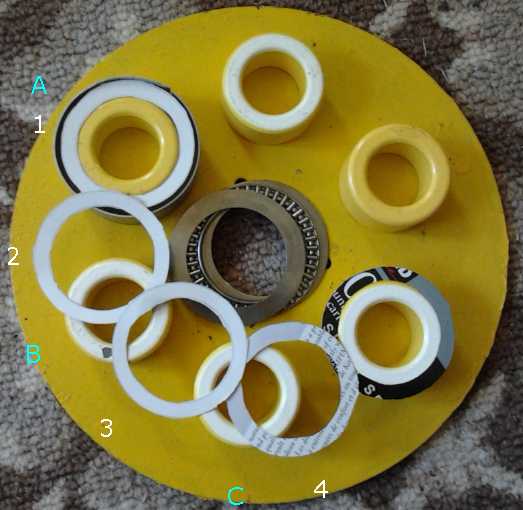
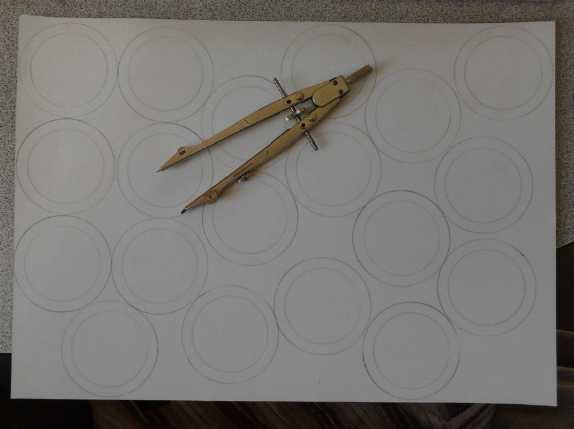
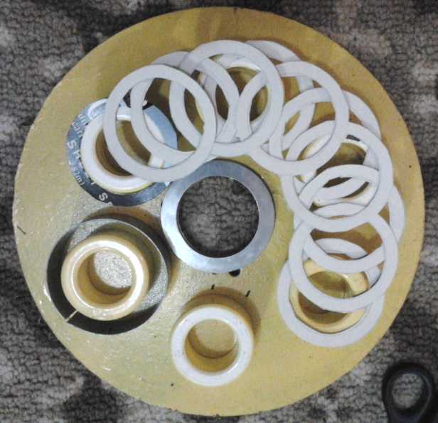
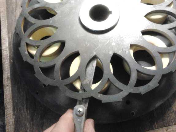
Even better, how about cutting rings out of paper and arranging them in
different patterns? First the 'ring draw' on a piece of cardboard. The
cutting was much slower than the drawing. I eventually cut 11, just the
number really required for the last layout.
Let's see... I
have the 2" O.D. donut coils, with the wire coils and then sheet metal
rings around them, making a ring of very high magnetic flux with about
2" I.D. and 2.5" O.D. What if I welded overlapping steel rings of that
size, maybe 3/16" tall, to a solid steel rotor, in a pattern such that
just as one is pulled into alignment with coil A, another ring is set
to pull onto coil B with high torque, and then the same for C, then A
again? One might
thus attain a large number of very high-force pulls per rotation. And
with just .25" wide walls that don't align with anything except right
where they're being pulled, the rings wouldn't exert much magnetic
drag. It sounds ideal. Now... how far apart and how many rings? I
figured
that would be best drawn on paper to get a sense of the geometric
proportions.
Even better, how about cutting rings out of paper and arranging them in
different patterns? First the 'ring draw' on a piece of cardboard. The
cutting was much slower than the drawing. I eventually cut 11, just the
number really required for the last layout.
I used six real coil cores roughly layed out
on a real rotor plate per the Electric Caik motor. (The thrust
bearing for visual effect would have been better if I'd straightened it
out.)
First arrangement is the unipolar motor controller's "normal"(?) 4
rotor elements per 3 coils. The fifth (dark) ring starts the second set
of three coils (A), (B) and (C), which is merely a duplicate of the
first set. This is 'theoretically' good, but (for
clockwise rotation) as rotor ring 1 lines up with coil A as shown,
having produced its thrust, rotor ring 4 would be too far from coil C
to have good torque at first. Each ring in sequence would be the same,
making
poor and lumpy torque.
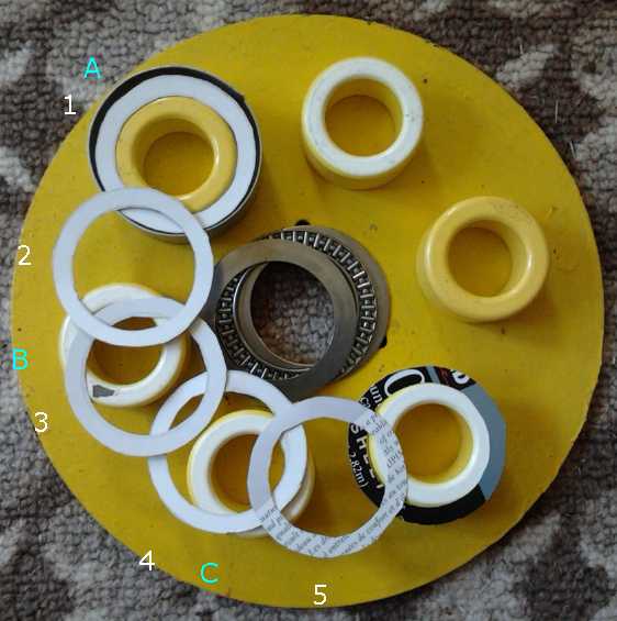 Next I increased it by one ring to 5. This
time, ring 3
would next align with coil B. It's getting better, but the metal of the
ring is still pretty
distant from the flux ring at first, which would make for bad torque
ripple with low torque areas.
Next I increased it by one ring to 5. This
time, ring 3
would next align with coil B. It's getting better, but the metal of the
ring is still pretty
distant from the flux ring at first, which would make for bad torque
ripple with low torque areas.
As with 3 rings, six rings per three coils would have all three phases
line up at the
same time, then there'd be no torque at all. No coil could be turned on
without producing reverse torque
as the motor went further. Depending on the starting rotation, the
motor wouldn't be
able to start, negating the whole point to having 3 phases 120
[electrical] degrees apart!
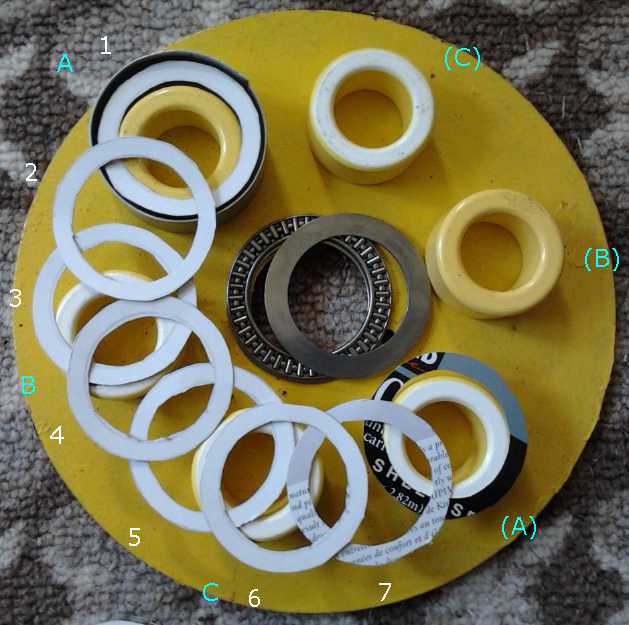 So the next choice would be 7 rings per
3 coils. At this point, there's a lot of metal, and we need to ensure
there's no undesired backward force seriously counteracting the forward
force.
So the next choice would be 7 rings per
3 coils. At this point, there's a lot of metal, and we need to ensure
there's no undesired backward force seriously counteracting the forward
force.
In this case, ring 6 is quite close to coil C, and should jump into
alignment with it when C is turned on. Since only coil C is on (one
coil ON at a time), alignments of other rings with other coils won't
cause backward forces. But looking more closely, I would hardly
trust ring 5 not to jump
backward to C instead of 6 to jump forward. They're too equidistant for
my liking, and the torque will be reduced until 6 gets
closer and 5 gets farther from the coil.
[Ignoring that...] Once 6 and C were aligned, 4 would be ready to
attract to B, and so on, and the energization sequence would be
CBACBA... Note that this is opposite to the 5 ring arrangement and the
same as the 4 rings. But that merely reverses the sense of the
forward-reverse switch.
If counterclockwise motion was desired instead, coil B would go on next
and attract ring 3 equally but opposite to C and 6, then ring 5 to coil
C for the sequence ABCABC...
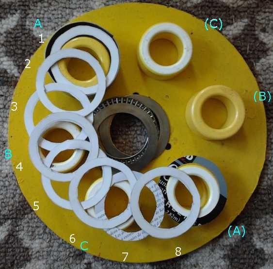
Finally(?) I tried laying out 8 rings per 3
coils. At this point
there's more metal in the rings than space in between. But is that bad,
or good?
Ring 4 [note: should be placed a little farther to the outside] is
almost aligned
with coil B, and it should have strong torque to pull into alignment
with it. Close together as the rings are, ring 3 is farther away so it
won't do much backwards force. Ring 5 will be minutely helpful, almost
canceling 3.
Then 7 will be equally close to C (as 4 was to B), and following that 2
will be ready for coil A to turn on. then 5 at B, 8 at C, and then 3 at
A. Two rings are skipped in each sequence, but they are different ones
in each successive sequence. This may be the highest torque arrangement
because the rings are each energized in turn just approaching their
highest torque area, in rather rapid succession, and nowhere else. As
it happens, the geometry just works out much better than with 7 rings
per 3 coils -- for these rings and these coils, at the spacings shown.
9 rings per 3 coils would again have rings aligned at all three coils
at
once and wouldn't have any torque to start at some points.
 I was pretty sure 10 rings
would have so much ring with so little space
between them it would start losing the torque by the coil attracting
more than one ring. Later I tried it anyway. Not only did that look
like a problem, but like the 7 ring setup, it looked like two rings
would be almost equidistant, pulling in opposite directions.
I was pretty sure 10 rings
would have so much ring with so little space
between them it would start losing the torque by the coil attracting
more than one ring. Later I tried it anyway. Not only did that look
like a problem, but like the 7 ring setup, it looked like two rings
would be almost equidistant, pulling in opposite directions.
Having so casually placed the coils, I later checked to see that they
were 7.75" at the outside diameter. [Electric Caik rotor size]. They
were about 8", so I adjusted them and tried again. The results were the
same. 3, 6 and 9 rings are out because they line up with all three
coils at once. 2, 4 and 5 left some large gaps - very low torque areas.
7 and 10 made for rings trying to pull almost equally in both
directions.
8 rings - doubling up the
'typical' 4 - looks like the
arrangement for good torque. This could make for some tricky
fabrication - cutting and welding or machining. Even the optical rotor
position sensing device will need 16 slots!
I was hoping it would want fewer rings. But that's why I cut all those
cardboard rings and layed them out; to find out. And now that I have,
it makes sense that if the ring width is .25" and each coil is on 1/3
of the time, the spaces between rings should be 1/2", which is about
what it is (widest part). But I only realized that after having done
the layout and perhaps because of it.
There will be 8 activations of each coil
per electrical rotation (one per ring), or 16 cycles per physical
rotation since there are 6 coils, two per phase, and so 16 rings.
That compares with just 4 for the BLDC4:3 motors and two for regular
2:3 BLDC.
The next morning (10th) I was casting around for materials
and ran
into a washer about the right outer diameter but with a little smaller
inside and so thicker walls. It occurred to me then that instead of
having so many rings,
one might simply make them like that - inside smaller or outside
larger. That way,
with the 5 ring system the edges of the rings would be closer to the
flux areas when they activated and there'd be more torque. In fact,
adjusting the ring size would be a way of fine tuning the torque ripple
versus peak torque. And the 1/3 metal to 2/3 space ratio could be
attained with the 5 or even 4 ring layouts. But fewer rings would
surely be lower torque. Or the rings could be
thinned a bit for the 8 ring layout if that seemed desirable.
One can of course try out new rotor designs for real in
one motor, by creating and mounting the desired rotor and an optical
sensor ring with the matching number of slots. The one that seemed most
advantageous would be kept.
And to skip ahead a bit, when I set the pieces together
after the rotor was made, the rings seemed a little more distant from
the coil flux rings for the starting rotation of each phase than I
expected, which will reduce the torque until they get closer. Thus the
torque may have a fair amount of ripple. Maybe I'll do a second rotor
with bigger outsides on the rings, which should solve that. Or maybe
check out 10 or 11 thinner rings, which just might make higher torque
than 8
after all (with of course higher coil sequencing speeds).
The motors in the research papers had two rotors, one on
each side of the stator. But absolutely flat, rigid and level
construction on all
points is
vital. I decided to try out a single rotor design - it would be way
simpler and more robust. It might be good to aim for about a .025"
(.6mm) flux gap. The
needle bearings hold more precisely than the automotive ("trailer
wheel") bearings, so they're the pick. The center holes will be
perfectly sized for them to hold them in alignment. The thrust bearing
will help
with precision leveling between rotor and stator. A flat plate of mild
steel would seem to be vital as the base for the stator both to hold
the coils exactly and to complete the magnetic circuits at the bottom.
As I thought about doing a drawing for the mechanic, I
started thinking more about having a circular bottom plate with a
center hole sized for the bearing cut by waterjet. And then, why not
waterjet cut the bolt holes for the coil holding bolts?... and then,
for everything else? And then, why not do a top plate, too? And why not
have the whole rotor, with optical interrupter holes and all those
overlapping rings cut out of a plate by waterjet, too? That would take
all the precision grunt work out of it. Any number of rings becomes as
simple as any other (except to the waterjet machine), and it makes it
easy to try out
the most promising ring layouts and variations of them!
Suddenly making an AFSR motor started looking, if not
trivial, at least simple enough. I called Victoria Waterjet and they
said they can use .DXF files. OpenSCad, the program I design 3D objects
in for the 3D printer, can export to .DXF. So I could create the
designs in software I already knew, and have them precision made:
BINGO! (And there I was, about to go down to Western Equipment to buy a
bunch of those washers, to cut them up and weld the pieces onto the
bottom of a steel disk!)
Next feature: Princess auto sells hubs that fit on a keyed
shaft to weld chain sprockets onto. I could make the rotor center to
fit one of those, and weld it. And I could machine out a bit of the
bottom end of the hub to fit it to the thrust bearing. Finally, a 3/8"
aluminum plate could be rolled into an outer shell (only about 3" tall)
with the metal roller at Victoria Makerspace, and then perhaps be
welded into a "perfect" tube. Or, given that SRM.s are said to tend to
be noisy, perhaps a PP-epoxy outer shell would be appropriate as a
sound dampener -- if the top bearing position could be centered
accurately.
Knowing how cramped it was inside the Electric Caik
motors with 7.5" diameter, I decided to use the 8" diameter to the
outside of the coil cores; 3" radius to the centers of the coils and
rings. That would leave more space for the optics and wiring in the
middle - and enough room for running wires between coils. By evening of
the same day, the 10th, I had the bottom plate and the rotor with 16
overlapping rings designed in the CAD program. Suddenly, the design was
coming together with blazing speed, with most of the nebulous loose
ends pegged!
I went through some SRM literature on the web late in the
evening. Before I went to bed, I had the thought to use the outer
curves of the rotor rings as the optical interrupter slots and solids.
The optics could be mounted on the outside wall - and probably would be
wired from the outside. This too seemed like a simplification, and I
had just the right opto-interrupter units for it. It looked like it
would be
faster and easier to make this motor - including the prototype - than
my BLDC motors.
What a long way this project came in two days! However, on
the 11th came a check. After figuring out how to export the files to
.DXF format, which to my surprise took the computer a couple of hours,
I drove out to Victoria Waterjet. As with the .STL files for 3D
printing, the .DXF curves were broken down into a series of short
straight
line segments. I was told those were very hard on the waterjet machine,
which would repeatedly stop at the end of each line and then restart in
the next direction, 'jittering'. The 3D printer doesn't stop, but I
know my
drill-router also breaks down G-code curves into line segments, and it
too stops at the end of each segment, so I was familiar with that, and
if it's a problem for the waterjet machine, I have to accommodate that.
That meant I'd have to find and learn to use another CAD
program that would put out .DXF files suitable for the waterjet
machine,
and redo the designs in it. This would take it from "done in a day" to
days or
even weeks, considering the learning curve for new software. I had
downloaded the 2D CAD program LibreCAD a couple of years ago, hoping to
use it
with the CNC drill-router, but it hadn't worked out. It was pretty
unintuitive. I had to ask the author how to do some pretty basic
things. It did them well if you knew how. But by now I had essentially
forgotten how to use it.
I went into AGO on the 12th and found they had an
assortment of CAD programs that did .DXF. I was given a CD with an old
MS Windows version of Autocad. But when I got home I thought an old
version of software might not be the best, and I decided to try
LbreCAD again ("better the devil you know" - tho I never really got the
hang of it before). The program was again unintuitive and the on-line
manual was sketchy at best. It was enough to get you to hurl
your computer out a window, but eventually I got the hang of some basic
things and suddenly most of the rotor layout magically appeared.
When I took that out to Victoria Waterjet the next day, it
was just lines and circles on his screen with all the solid and area
"fills" missing, but he managed to cut, paste and manipulate it (using
a CAD program called Rhino3D, 700 or 800$), which he
manipulated with great ease and familiarity)
until it was how I wanted it. I did up the bottom and top plates on the
morning of the 14th, and
simply e-mailed them. Then it was just a matter of waiting for them
getting around to
it. I didn't ask how many weeks that might be. I was leaving for a week
holiday anyway.
Here are the .DXF ("Drawing eXchange Format") files as
done in LibreCad, which as I found may need some tweaking when applied:
AFSRM-Top-Plate-LCad.dxf
AFSRM-Rotor-LCad.dxf
AFSRM-Bottom-Plate-LCad.dxf
Note: I moved the three bearing holder holes outward a bit on the
bottom plate to miss the thrust bearing. I threaded the plate holes,
filed the square bearing holder holes outward a bit, and used regular
5/16" hex head bolts. This was unnecessary on the top plate. They
should be moved in to (IIRC) 1.5" radius from the axle and cut to 5/16"
diameter. The center bearing holes are sized to form one side of the
bearing holder, so only one pressed needle bearing holder is used
instead of two.
Aside from the top and bottom plates, the other body
component is the outer rim. As long as it's stiff and the right
diameter (10"), I think it could be anything from aluminum to PVC. A
plastic shell might help dampen vibration and noise. The coils are
1.0"... the rotor is .025" above the coils and is .25" thick, and the
hub sticks out maybe .125" above that... clearance from hub to upper
plate .05"... The thrust bearing might add .1" or less. That's a
whopping 1.55" height needed on the inside, for a total of just over
2". (That doesn't count how far the bearings and shaft stick out.)
Remembering having to raise the Weel's sides later I'll give it some
extra height, but even at 2.5" x 10" it looks like this is going
to be one very skinny pancake motor! It will however weigh about 25
pounds, 10 pounds heavier than the present Electric Caik. I could
change the top to aluminum and save a couple. The bottom needs to be
very stiff, and also to carry the magnetic circuit. But perhaps that
too could be replaced by a thicker slab of aluminum and some steel
rings under the coils to lighten it a bit more, and at least get it
under 20 pounds or so.
When I returned from vacation, I found that someone had
e-mailed me a link to a "Transverse Flux" BLDC motor. After thinking
about this for a day or two, making a reluctance motor with a similar
layout seemed so promising that I e-mailed Victoria Waterjet and asked
them to cancel cutting the axial flux design. But it was too late. So I
decided I would make this design first while I thought about the new
one. At least I'd be able to compare two quite different designs, one
done with iron powder in the coils and the other with mild steel, and
see what happens as the RPM goes up.
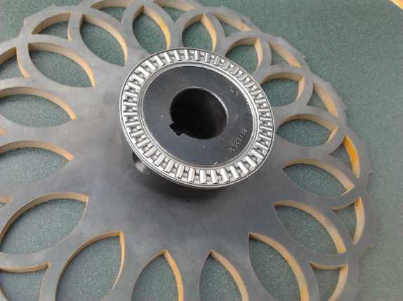 On the 25th I picked up the cut parts. I had to file out the center
hole of the "lacy" rotor a bit to fit the center hub. (Better that than
too loose!) Then I turned down the center hub on the bottom to fit
inside of the thrust bearing. The bottom ring of the bearing was to go
in an indent on the bottom plate, which at 10" diameter with an odd
size center was too big to turn on my lathe. I took it down the street
to AGO Environmental Electronics for the machinist there to do, and it
was done the next morning.
On the 25th I picked up the cut parts. I had to file out the center
hole of the "lacy" rotor a bit to fit the center hub. (Better that than
too loose!) Then I turned down the center hub on the bottom to fit
inside of the thrust bearing. The bottom ring of the bearing was to go
in an indent on the bottom plate, which at 10" diameter with an odd
size center was too big to turn on my lathe. I took it down the street
to AGO Environmental Electronics for the machinist there to do, and it
was done the next morning.
 After getting the waterjet cut steel parts I
made an aluminum body ring, threaded the case bolt holes,
After getting the waterjet cut steel parts I
made an aluminum body ring, threaded the case bolt holes,
and put together the case to see what it looked like. Everything seemed
to fit together nicely.
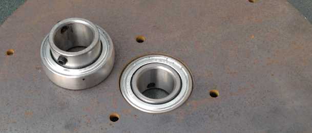
Inside: bearing with rounded edges only goes part way through.
Outside: regular pressed bearing holder holds bearing centered in hole.
With these thick steel plates for stiffness, it'll weigh almost 25
pounds. One might try, say, 3/8" aluminum for the top plate, 1/4" steel
for the bottom, and 3/16" for the rotor, to lighten it up. ...if the
bottom plate and rotor don't flex too much and close the flux gap
during operation.
The next question mark was details about making and
mounting the coils.
I may "fill in" the centers with epoxy, or PP epoxy, somewhat recessed.
Presuming that will stick to the cores, it'll give something solid for
the coil bolts to go
through without anything sticking up above the 1.00" tall cores. The
cores will only take 9 wires (11 AWG) when they can't stick out the
slightest bit top or bottom, so 18 wires in 2 layers instead of 21. (It
can't extend to 3 layers because the steel ring has to fit to the
outside.) Unless
I put the wires into the rolling mill and flatten them just a little
bit. But then, could they be kept straight "on edge" while winding
anyway? I had my doubts, and decided to just use 18 turns. At worst, a
little lower torque, power, and voltage than it ought to have. Since
it's so hard to estimate what it'll have to start with, I can just add
15% to the figures if I figure out a way to wind them better. Maybe
micrometals.com has some slightly taller toroids?
 On the 27th I
fiddled with the rotor/bottom plate assembly and 6 toroidal cores with
no wires. First the rotor plate wouldn't quite fit down onto the hub. I
figured the inner lip of the hub must be slightly rounded, and I filed
out the lower edge of the hole in the rotor at a 45° angle to
match. This time it went on with no gap showing anywhere between rotor
and
hub.
On the 27th I
fiddled with the rotor/bottom plate assembly and 6 toroidal cores with
no wires. First the rotor plate wouldn't quite fit down onto the hub. I
figured the inner lip of the hub must be slightly rounded, and I filed
out the lower edge of the hole in the rotor at a 45° angle to
match. This time it went on with no gap showing anywhere between rotor
and
hub.
The fronts of the rings seemed a little far from the
highest torque areas at the point where each coil would turn on, which
may make for weaker torque points - torque ripple. If measurements
indicate, I may want to try a rotor with rings of slightly larger
outside diameter later.
I wanted the rotor to sit and turn about .025" above the
coils. To get this, the rotor hub and bottom plate had to be carefully
turned on the lathe to set the hub the right height on the thrust
bearing. After measuring things with a feeler gauge for a while, I
decided to take the hub down a few thousandths of an inch. After that
it seemed about right. It didn't turn with zero wobble, and different
coils had different clearances, meaning the base wasn't totally level,
flat and even. The lower ring didn't sit flat, but on further
examination, it was the thrust bearing's race ring that was slightly
bent, not the bottom plate. But it was close enough, and I couldn't
flex the rotor enough to make it hit the coil cores.
It became a
slightly different story when I wound the coils on the 28th and 29th.
It was easier to say "absolutely no protrusions above or below the
cores" than to achieve that when confronted with wires that
weren't perfectly straight, gooey, slick wet epoxy, side guards of
plastic that
annoyingly insisted on curling in under the windings, and a winding
setup that wasn't made to prevent said protrusions. Some made it, a
couple didn't.
I finally decided that instead of winding more coils and
trying to achieve ultimate perfection in the prototype I would match
each coil to a specific position and grind a dip into
the plate where the offending wires would touch it. (I had got used to
there being no chance of coils causing shorts with the PP-epoxy plastic
cases in the BLDC motors!) And if necessary I'd add enough of a shim
under
the thrust bearing lower ring so that
everything had clearance, even if it would result in more than .025"
gap most places. IF I
stick with this model I can improve the winder pieces, and make 6 or 9
winders
so all the coils of a motor can be done at once instead of two at a
time, to make it considerably easier and faster. (The epoxy
must set in the oven for an hour after winding.)
I finally decided to epoxy the outer rings onto the coils
first, then
sand them to exact 1.00" evenness. Then I'd epoxy the finished coils
onto the plate, making a thicker patch of
polypropylene-epoxy in the center of each coil. The patch, covering the
mounting holes, could be drilled out and nylon(?) bolts threaded in to
better secure everything. ...or maybe just use lots of epoxy all over
to glue them down, maybe in 2 or 3 coats? Being on the stator, they
wouldn't have to endure centrifugal force.
Rotor and coils on bottom
plate. (Rim and top plate behind.)
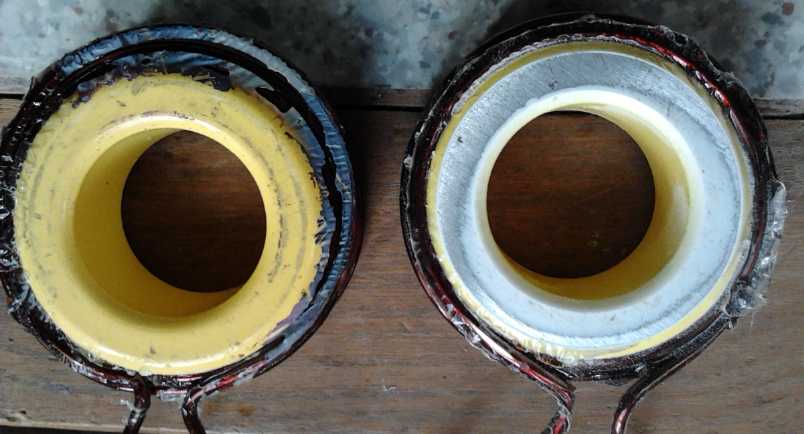 I found a "hidden" item 'invisibly' increasing
the top and bottom gaps:
the paint on the coil cores is at least several thou thick.
I found a "hidden" item 'invisibly' increasing
the top and bottom gaps:
the paint on the coil cores is at least several thou thick.
Ideally it should be sanded off. (Note the sanded spot on the wire
insulation - it
protrudes past the end where it shouldn't.)
Also note the apparent solidity of the "iron powder" core. An ohmmeter
shows that the iron particles are in fact not
insulated from each other, although the resistance is high enough to
prevent significant iron conduction losses.
I conclude that they are probably sintered iron powder cores,
or at least that the particles are pressed together with many tons
of force. I didn't see that on the manufacturer's web site.
(micrometals.com) This is merely an observation.
But also the sanding reduces the grainy appearance of the iron.
If I was making iron powder components myself I expect I would simply
use epoxy saturated with iron powder
and pour it into a plastic mold because it would be easiest for me to
do. But it might not work as well.
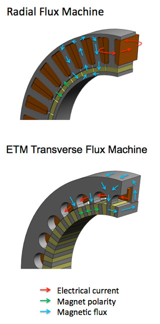
Another Layout: "Transverse Flux"
Motor
 Just when you think your design
must be pretty much the best thing going, somebody comes up with
some great new idea. After my exciting new "ARM" motor was all in train
and
the designs for the steel parts were at the
waterjet company awaiting cutting, someone sent me a link to
a website with an interesting new "transverse flux" BLDC motor layout,
which looks like it should adapt well to the SR motor type. [ http://etmpower.com/
] It took me a while to figure out from the diagram just what was
happening. The on-edge magnets with the "offset horseshoe"
electromagnets should make impressive torque. It seems to show only one
phase, presumably of a 3-phase
motor if one wants torque at all points of rotation. I don't see any
way the phases
could be interleaved in one stator, so I guess they must go side by
side, making the rotor also 3 times as wide, which seems
like a waste of magnets and rotor material. But perhaps it isn't once
it's
all calculated out -- and the SR motor won't be using any magnets.
Just when you think your design
must be pretty much the best thing going, somebody comes up with
some great new idea. After my exciting new "ARM" motor was all in train
and
the designs for the steel parts were at the
waterjet company awaiting cutting, someone sent me a link to
a website with an interesting new "transverse flux" BLDC motor layout,
which looks like it should adapt well to the SR motor type. [ http://etmpower.com/
] It took me a while to figure out from the diagram just what was
happening. The on-edge magnets with the "offset horseshoe"
electromagnets should make impressive torque. It seems to show only one
phase, presumably of a 3-phase
motor if one wants torque at all points of rotation. I don't see any
way the phases
could be interleaved in one stator, so I guess they must go side by
side, making the rotor also 3 times as wide, which seems
like a waste of magnets and rotor material. But perhaps it isn't once
it's
all calculated out -- and the SR motor won't be using any magnets.
The coil winding should be very simple since each phase is
just a
single large coil wrapped right around the entire stator. (Probably the
stator should be made of iron powder, but I'll do a prototype from
waterjet cut steel pieces to make a lower RPM version just
to try it out and check the construction layout, and test the torque et
al. With really good luck, I just might find solid mild steel is fine
for
the
desired RPM range anyway.)
The flux goes around the coil wire, transverse to the
stator in any
direction, so it could equally have the rotor inside the stator,
outside, or axially, by aiming the stator "teeth" and rotor poles/lobes
in the appropriate directions.
For axial flux and flat rotor for a "pancake" shape, one
could put
one phase on each side of the rotor, but I don't see where the third
phase could fit without adding a second rotor. On the other hand
there's nothing intrinsically evil about a radial design. Since the
coil wires aren't run around the teeth, one
could make the parts with quite thin stator 'teeth' and rotor lobes. It
could be stacked with lots of them like gear teeth, making lots of
magnetic interaction points. Where my layout has two fairly large rings
active at any one time, this could have maybe a couple of dozen finer
lines. So the issues mentioned for radial designs in
the AFSRM research papers could disappear - perhaps plenty of torque,
even very high torque,
can be developed. And the radial direction (with magnetic points all
around the circumference) also
puts no axial bending stress on the rotor - a distinct advantage with
the tiny flux gaps. The thrust bearing,
handling of such loads, and precision axial placement become
unnecessary. I feel this is moving beyond the dual rotor AFSRM.s in the
research papers - they are no longer my "design models" to follow after.
But the rotor needs a wide, "toothed" outside rim, hard to
cut in one piece with the waterjet, and if it's solid it'll be very
heavy. It might be made as some sort of cast part, a bit like a
large-rim gear or a brake drum with outer "teeth".
I visualize, perhaps, a stator with 3 side by side rings
of inward facing horseshoe magnets, offset for the three phases, and a
rotor with wide teeth across its outer rim it to match up with all
three in sequence. Or perhaps the 3 horseshoes could be in line and the
rotor lobes skewed instead (made from three pieces)... perhaps less
width would be required that way. Hmm, maybe not. Either way, it's like
putting a bar across the horseshoe magnet. The force pulling it to
center is strong. As I figured this all out, I sensed that here was an
even better, even easier
to make, new motor design! I'm starting to wish I just
wasn't seeing them! I can hardly settle on one design when I keep
seeing something markedly better can be made! At least - so far - it's
the same new motor controller for any of these new motor designs.
Let's see... use 1/4" mild steel for all the stator
pieces. One with the teeth facing inward to go on one end, one full
diameter but jut a ring around the outside in the middle. The wound
coil wire goes inside from this. Then another piece the same as the
first, the three forming the ring of inward facing "horseshoe"
electromagnets. And they'll all have bolt holes at the same points of
rotation so they all line up when bolted together.
One piece will need a slot for the coil wires to
come out through. Hmm... or they could come out at one end, through the
gaps between the stator horseshoes. Since the pieces are bolted
together the finished (epoxied?) coil can simply be placed in the right
place during assembly.
The teeth will be 1/4" wide. If they were ~1/2" long there
would be 17 teeth in an 8" rotor, with ~1" gaps between them. The rotor
would need teeth 1/2" long and 3/4" wide, the width of the three stator
pieces. For the 3 phases, it would need to be 9/4" or 2-1/4" wide. This
will probably be the hardest part to make. Waterjet cutting it from
multiple pieces of mild steel would make it very heavy. (But it should
be possible to cut them from the pieces left over from the stator rings
- they should be pretty much just the right size.)
The second stator phase would be identical to the first,
but the bolt holes would line up so the horseshoes are 1/2" (1/3 of a
tooth spacing) rotated from the first phase. The third phase would be
another 1/2", and the next 1/2" is phase A again. A 1/8" gap could
perhaps be left between phases, making it all 2-1/2" wide instead of
2-1/4". The gaps would isolate the phases magnetically (hmm... is that
useful?) and assist with cooling.
Or instead of 1/4 x 1/2" teeth with an inch space between
them, one could put in twice as many 1/4 x 1/4" teeth, with 1/2"
between them. (34 teeth for an 8" rotor.) The coil sequence would
switch twice as fast. Would that give more flux than 1/2 as many of the
larger size? Probably. For once, one of those computer flux simulation
programs just might be useful. Maybe.
I'm not sure of the best approach to the optical rotor
position sensing. There are a couple of ways I can think of offhand but
nothing very convenient. The LED.s and phototransistors certainly can't
go across a 2+ inch wide interrupter tooth gap.
Considering the three stator phases side by side, and that
they have no wire overhangs sticking out the sides: if they are only
3/4" wide each, (or even 9/16" using 3/16" thick plates), this radial
layout motor is actually thinner than my axial flux BLDC pancake
motors. Flat covers could perhaps be bolted right onto the outside
edges of the stator, and depending on the rotor, the bearings could be
pretty much internal. This might make it not much more than 2.5"
across. (And here I thought having the 3 phases side by side would be a
waste of space and material!)
And while the outside stator theoretically adds diameter,
the flux
gap is tiny, and the stator itself forms the outer casing. It's
probably only a little diameter increase over the axial flux machines
with no active parts outside the rotor, but with a ventilation air
space and a 1/2" thick outer protective rim. (The contours of the
radial design will provide air cooling spaces despite the tiny flux
gap.) So it's definitely smaller overall.
And if the many magnetic flux points should provide the
same torque with a smaller diameter rotor, the whole motor will be
downsized -- or will have more torque in the same diameter.
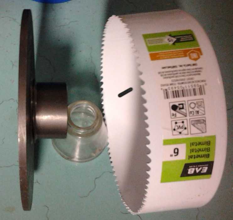 Toward the end of the month I found a 6" drum -
a circle cutter rather than a brake drum - and a 6" rotor
Toward the end of the month I found a 6" drum -
a circle cutter rather than a brake drum - and a 6" rotor
with a 1" I.D. shaft hole. I would turn the rotor down a bit so it
fits,
tightly, inside the drum,
adding the center axle interface and better stiffness.
The cross bars can be bolted to the outside through holes in the rim
(different widths could be tried),
or the voids between the bars could be cut out of the drum rim so the
rim forms the bars.
Neither of those sounds as precise and well balanced as waterjet
cutting or machining.
Making an
"Electric Hubcap" Plug-in Hybrid EV Installation by the New Plan
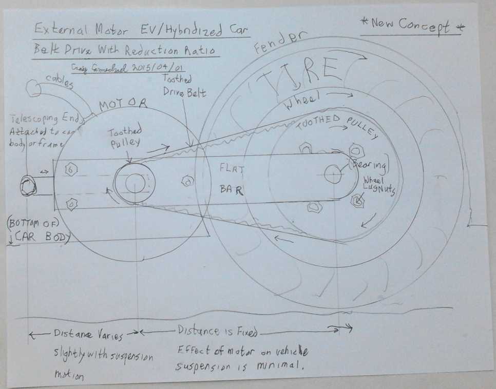 Concept for wheel drive motor assembly
[TE News #86]
Having determined what seems like a better way to mount a motor to
drive a
wheel, and with the tire off owing to some brake trouble, I removed the
"Electric Hubcap" mounting tubes that have extended from behind the
wheel to the front for 5 or 6 years. (One was pressing a bit on the
parking brake cable, and it had eventually perhaps become slightly
kinked,
jamming and holding the brake on while driving. That was the apparent
problem, but I remember that same brake cable sticking over a decade
ago, too. I managed to free it up at that time with some oil. No such
luck this time!)
Then, having given it some thought, on the morning of the
15th it
came to me that a 1" or 1-1/16" trailer stub axle with four bolt holes,
just such as I had tried out in 2009-11, was the right piece. It
attaches to the car wheel against four extended lug nuts by short 12mm
bolts.
Its holes are actually a 4" (101.6mm) spread, but a little filing on
the inside brings them down to the 100mm spacing of many 4-bolt small
car wheel lug bolts.
With this sticking out from the wheel (about 6-7" long),
first a spacer is used to place the drive pulley out past the body of
the
car. (It looks like it should be about an inch wide - or maybe I could
cut off the mud flap and have little or no spacer.) Then the pulley is
bolted on to the spacer to turn with the wheel - to turn the wheel.
(The details remain to be worked out. If toothed belt pulleys and parts
prove too hard to get, a heavy chain and sprocket gears could be
substituted.) Outside of that, a cut-down
trailer wheel hub is placed on bearings on the axle. Then a spacer (if
necessary) and then the axle nut and cotter pin on the outside.
The hub makes a perfect, stable place to mount the wheel
end of the motor bar. Instead of being a flat piece, the 'bar' will
have sides going inward all around as a guard over the belt. Thus it
will look like a belt guard, but it will be made stiff enough to
carry the motor and the tension of the drive belt.
Since the hub on the wheel holds the motor bar and
prevents it from twisting, all that's needed at the rear end is a
single hinge or pin to the car body or frame to hold the bar
horizontal. This has to be somewhat flexible so the bar can move back
and forth a bit as the wheel bounces up and down on road bumps, and the
single attachment point makes this easiest to do. Centering the car
attachment point on the motor axle is ideal, but anywhere near the
motor will do.
I actually had most of the required pieces including a
sample toothed belt pulley and a cut-down trailer wheel hub, so I took
them out to the car to demonstrate how they would fit and take
pictures. It'll probably want a larger pulley (or chain sprocket), like
maybe to 10" to 12"
in diameter, and the trailer wheel hub that the 'bar' attaches to could
be cut down just so that it fits the shaft and the regular cap can be
put over the end of the axle.
The motor mounting bar should go pretty much straight back
(horizontal) from the trailer hub, with its sideways guards covering
the belt and pulleys. The motor would bolt onto the outside, with the
shaft and pulley sticking through to the 'guarded' inside. Again the
motor would be a "pancake" variety, not one that would stick out a long
way to the side, which could also put strong twisting forces on the
mounting bar.
The horizontally flexible bar-to-car linkage/attachment
pin remains to be worked out. It might go
through another plate with a slot, welded to the main 'bar' but behind
the motor pulley. There'd be a bolt with a large washer on the end of
the pin so the assembly can't slide off the end of the pin. (and
another washer inside so it can't slide in and the pin touch the
pulley.)
Obviously it'll be harder to change a tire, but not as bad
as previous arrangements. One can (I expect) simply undo the four bolts
from the wheel and drop the wheel end of the bar down any available
amount - and it's not very heavy, the motor end being still supported.
Maybe swing it outward a little if
some good slack was left at the pin end mounting. Then the wheel can be
removed and replaced as normal.
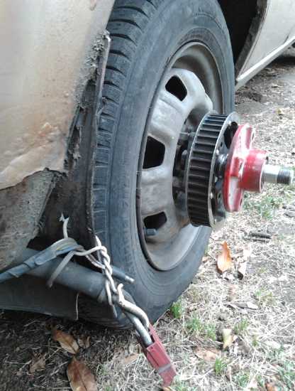
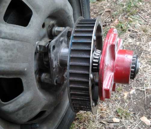 Two more views: from rear, 'exploded'
Variable
planetary gear transmission with Centrifugal clutch in Chevy Sprint
I started by trying to get the LED headlights working,
since I already had half the dash apart. I grounded the "always hot"
pins at the lights, and changed the headlight switch to supply +12V
instead of ground... but no
+12V was getting to the headlights. What was between the switches and
the headlights? Nothing, according to the Chilton's manual. The Haynes
manual showed something about "daytime running lights" from 1990 on,
but although I have a 1990, it has 1989 construction
including a carburetor instead of fuel injection, the engine plate
indicates 1989, and separate buttons for the headlights instead of a
combo switch. I wish I had just left the headlights alone. But it
turned out that even re-wired back to the original the halogen
headlight would only activate on "flash". Apparently there would be no
way around dealing with it.
Next I removed the entire shifter cable, which I found
could be pulled right out of the cab into the hood compartment through
its little hole, fat sections and all. There was no way to get all the
stuff off it, and it came to me that I'd probably be better off making
a whole new cable, the way I wanted it. The next morning, the 3rd, a
better idea came to me: cut the outer end off and keep the whole cable
with the inner end. That way the inner end was already done. I cut it
with a zip disk, which went through in 2-3 seconds. I found I could
salvage the crimped-on end bits after all - the rod (if I could get the
old cable out and crimp in the new end) and the rubber boots and outer
clamp pieces. One part of the puzzle was coming together, except that I
couldn't run it through the firewall where I wanted because there were
obstructions there. Well then, perhaps I could make it pull a pivoting
lever
that pulled the tensioning rope? That should work.
That was as far as I got when the first new idea for an
improved reluctance motor lured me away.
Other "Green" Electric Equipment Projects
Solar Hot Water Heater
On the 8th I thought again about the solar hot water (TE
News #88). In a house where people are living, it's the best way to
reduce the electricity bill. Solar electric is great, but the panels
are only (say) 15% efficient at converting sunlight into electricity.
So to gain the heating power of a 32 square foot solar direct water
heater - call it 60% efficient(?), 128 square feet of solar electric PV
panel is required -- 7 or 8 solar PV panels. give or take a couple. (or
it might be less as they seem to be getting more efficient.) A 2-2/3' x
12' solar hot water collector can go just above the eaves, below where
four of the existing PV collectors are mounted, and without producing
electricity itself, do more to cut the regular electricity bill than
all of them.
There were the plastic swimming pool collectors I bought a
couple of years ago, thinking to make a quick and easy pumped system.
But I really prefer the simplicity and automatic operation of
thermosyphoning - water flow by convection. In spite of needing large
pipes that can take city pressure at hot temperatures, and having to be
drained down (or the collector to be heated) in winter, a
thermosyphoning system has its own savings in parts and headaches. And
the tank can easily be connected to the woodstove for winter water
heating, which can save even more than the solar, and in the winter
when the water coming in is coldest and there's no sun.
So I decided I'd try to put a 'proper' copper collector
panel together, similar in size and shape to the one I made in 1979.
Since copper pipe is rather costly I went to Ellice Recycling to see
what they had. I wanted 2-1/2' pipes, but they had a lot that were just
2' long. I had a few thin aluminum fins that clipped onto 1/2" copper
pipe and could buy more, to paint black and form the collection
surface. They are also 2' long. And they are 4.75" wide, so I'll need
about 30 of these 2' pipes soldered between two 3/4" diameter, 12' long
header pipes.
Then I figured that I could and should have sun collection
fins on the top and bottom header pipes as well as on the riser pipes,
and that the fins above the top pipe and below the bottom could add
about 3+3=6" to the height. That would give the desired 2'8" collector
panel height. (2-2/3' x 12' = 32 square feet.) I might even have to
make the fins 2" or 2.5" rather than 3". And I was pretty sure I'd have
to make them, that they are only available (at least at the one store I
know of that has any at all) for 1/2" pipe.
I've come to hate fiberglass with a passion. I decided to
look for some alternative insulation that would withstand the somewhat
high temperatures in the collector under the heat fins and copper
piping. And what for the solar preheated hot water tank? These days,
hot water tanks usually have expanded foam insulation except right
around the electrical connections, where you're left to deal with...
ugh, fiberglass! Perhaps I could do it like the Peltier module fridge:
use 2" extruded expanded polystyrene foam construction sheets, cut to
fit around the tank, and 'glue' them together and more or less seal
them to the tank with a can or two of spray foam. And some packaging
tape to hold it all together while the stuff hardens. I don't think it
needs an outside shell unless it's to keep rats from chewing on it in
the attic. Hmm... maybe (again like the fridge) some naugahyde wrapped
around it. Foam pipe insulation is of course readily available for the
pipes.
On the 22nd I bought some more copper pipe. I weighed some, and
discovered that brand new pipe wasn't so much more than salvaged, when
the salvage price was 5$/pound. (I can't believe they get anything like
that much when they ship it out.) But I decided to use 1" header pipes.
These were about 55$ each before taxes for two, and the bill (with a
pipe cutter and 4 fittings) came to over 300$ at the plumbing supply.
Now I remember why alternatives to copper are ardently sought. But it's
the best for a collector (and probably woodstove connected) system that
might get quite hot.
An opposite problem is cold. I'll circulate house water
through the collector and into the tank to keep the plumbing simple.
There will of course be valves but it's a pain to drain the collector,
high up on the roof with valves in the unfinished attic, for the
winter. I keep thinking a small heating element in the collector's
lower header pipe, with a thermostat set just above freezing, would
cause the water to circulate to the tank and prevent everything from
freezing.
On the 28th I drilled thirty 5/8" holes in one of the 1"
pipes to silver solder the 1/2" riser pipes to. Was I really going to
do 60 silver solder joints, each with the chance of a leak, for just
two foot long risers? That seemed like an awful lot of heating and
soldering for such a small bits of pipe. Maybe I should make it 6' x 6'
- cut the soldering in half and have more collector area? But that
would interfere with the thermosyphoning unless the tank was mounted
horizontally near the peak of the roof. Or 4' x 8'? I decided not to
decide and left it sitting.
On the 31st I decided the riser pipes would be 3' and the
collector 8' wide. A 4' x 8' piece of clear plastic (lexan?) would
cover the top with a bit of overhang. I tried to fit the pipes and they
didn't go in the holes easily. But if they weren't a close fit, they
couldn't be sliver soldered. I wished I had had something other than a
twist drill, which doesn't make very exact holes in thinner material
like pipe walls. Then I tried to solder in a pipe. While the silver
solder fell off the wire and beaded up, I couldn't seem to get the
copper hot enough for it to flow with the propane swirljet torch. Of
course, there's a big copper pipe carrying off the heat, and the slower
the heat, the more it spreads out without getting the heated point up
to the required temperature. Next try will be with a scary old naphtha
gas torch someone gave me. It really puts out heat.
Peltier Module
/ Thermoelectric Cooler
Experiment
When I returned from camping I thought to test the cooler.
It obviously wasn't working as well as when it was new. Originally it
could get down to 5 or 6°C. This was
doubtless because I had taken it apart to "reverse engineer" it and I
had tried various things with it. I hadn't then planned on ever using
it,
and while I kept it and threw the parts back inside, I wasn't as
careful as I might have been. I couldn't find the original aluminum
cold transmitting block, and I probably hadn't put it back together as
well as the manufacturer. After all this time (and being unable to find
its plug-in power supply), it occurred to me I could run the cooler
from the lab power supply, and also that in doing that I could try out
different voltages to see what results they gave, and see if they were
in
line with my complaint that peltier modules should be run in their most
efficient range, like 8 to 10 volts, instead of 12 to 14 volts, for a
15 volt rated module.
The converse of that of course is that for the ubiquitous
power supply voltage of 12 to 14 volts, one should use a peltier module
rated between about 18 to 24 volts (around 152 to 203 thermocouples
instead of the ubiquitous 127) to get higher efficiency operation, at
least for camping coolers cooling by around 20 to 30°C or less. Why
is it such modules hardly seem to exist, while 127 element modules are
"a dime a dozen"? This has been a source of frustration almost from the
start of experimenting with them.
A related observation is that with the solar collector
putting out nearly 14 volts all day, the 15 or 16 volt rated peltier
modules in the peltier fridge are being driven pretty near their upper
limit, which probably has a lot to do with the short service life I've
been finding. That's just one more reason not to drive them so hard.
From the 23rd on, I left the cooler running at each
voltage for at least several hours, usually a day or more, for the
temperature (taken at the floor of the cooler) to stabilize. I got the
following results.
Date/Time
|
Volts
|
Amps
(Approx)
|
Watts
Consumed
(Approx)
|
Cooler Bottom
Temperature
|
Room
Temperature
|
|
|
August 24th
|
7.0
|
2.5
|
14
|
12.3
|
23.5
|
|
|
August 25th
|
8.0
|
2.5 (?)
|
20
|
11.2
|
23.4
|
|
|
August 26th
|
9.0
|
3.3
|
30
|
9.5
|
~23
|
|
|
August 26th (from 9AM, readings 3PM)
|
10.0
|
3.7
|
37
|
9.8
|
~23
|
|
|
August 26th (from 3PM, readings 9PM)
|
11.1
|
4.2
|
47
|
9.9
|
~23
|
|
|
August 27th
|
12.0
|
4.5
|
54
|
10.7
|
~23
|
|
|
August 28th
|
9.0
|
- (not read)
|
- (30?)
|
10.9
|
~23.5
|
|
|
August 30th
|
10.1
|
3.7
|
37
|
9.6
|
~22 (cooler)
|
|
|
Everything seemed great up to the 27th. It seemed to be
proving my point quite well. Then I set it back to 9 volts from 12. But
the temperature didn't go back down to 9.5°. Instead it went up to
11°. The reason for the change was likely moisture build-up inside
the cooling unit, and probably frost buildup on the peltier since the
heatsinking didn't seem very effective. The next day I opened the
cooler, and sure enough a puddle of water drained out of the cooling
unit. So the tests probably were showing as much the moisture
conditions as the intended voltage versus cooling relationship. I
turned it off. I should probably turn the cooler off for a day to warm
up and dry out before trying each new voltage, and then take the
readings after a specific number of hours, say 6 or 8 - as if I could
remember to return at the right times - and just when it had been
turned on. On the 29th I tried 10 volts in the aired-out cooler. But it
didn't seem to improve it.
It then occurred to me I could also try out the
thermoelectric fridge with the power supply at different voltages. That
will be a better test than the poorly functioning cooler. And then I
could try out the large, 14 amp (but still 15 volt max - arg!) modules
at reduced voltages. Somewhere in there there should be more cooling
capacity at the same or lower power. Assuming I get such results, the
obvious next step (unless some better configurations of peltier modules
at a reasonable price make an appearance) is to make a DC to DC power
supply that takes the 12-14 volts from the solar collector and reduces
it to the optimum voltage, probably between 8 and 10 volts. Preferably
a switching supply of over 80% efficiency. (Let's see... getting 9V
from 13.5V with a linear regulator would be 67%. 10V from 12V would be
83%... the linear regulator is probably good enough since there's lots
of power when the sun is out.) But it's all unnecessary losses - a
peltier module optimized for efficient operation at 12-14 volts and for
fridge/cooler temperatures (ie with ~160-210 thermocouples instead of
127) would be better.
I can make a DC to DC switching power supply for dropping
voltages if I run out of other things to do. Including a model for LED
lighting. Meanwhile... 3 or 4 ten watt resistors could drop the voltage
to the solar fridge?
http://www.TurquoiseEnergy.com
Victoria BC Canada