Turquoise
Energy Ltd. News #92
covering September 2015 (posted October 4th)
Victoria BC
by Craig Carmichael
www.TurquoiseEnergy.com
= www.ElectricCaik.com
= www.ElectricHubcap.com
= www.ElectricWeel.com
Highlights: Free Energy from Thin Air?
- Lambda Rays, or Atmospheric Electrical Charge? (see Month in
Brief, Electricity Generation)
Month In Brief
(Project Summaries)
- Further peltier module 12 V fridge experiments - ARM Reluctance Motor
Runs! - New (used) Batteries NiMH & Lithium iron phosphate - Free
energy... where's it from again? - Timing of inventions, a perspective.
In Passing
(Miscellaneous topics, editorial comments & opinionated rants)
-
Syrian Girl's video: an 'on the
spot' perspective on what's happening in Syria - Loose Change -
Perpetual War - Arguably somewhat humorous things & "Political
Spin".
- In Depth Project Reports -
Electric Transport - Electric Hubcap Motor Systems
* ARM reluctance motor project
* "Transverse flux" SR motor rotor idea
Other "Green"
Electric Equipment Projects
* Peltier Module/Thermoelectric Cooler ('TEC') Experiments:
supply
voltage versus attained cooling - 15 amp Peltier module - better ice
tray - internal fan - evacuated tube heat radiator - DC to DC converter
* Water Conservation: Best Shower Nozzle and Video
Electricity Generation
* Electrostatic Perpetual Motion Motor?
* Thomas Henry Moray: not only free energy collector -- he invented
semiconductor electronics, in the 1920s... and lots more!
* Free energy from the electrical charge of thin air?
Electricity Storage - Turquoise Battery
Project (NiMn, NiNi), etc.
* Honda Insight NiMH Battery - converted to 14.4 volts, 65AH.
No Project Reports on: Variable
Torque Converter Transmission, CNC
gardening/farming machine, Electric Weel, battery making, aquaponics,
Magnet motor project.
September in Brief
My motors have evolved from "gosh it turns" in 2008 to
BLDC motors with excellent specs but not very well built, to
much improved constructions, then in recent months to a new BLDC plan
with double the magnet poles, and now to the first of two latest
switched reluctance
designs of great promise, the "ARM" which first ran on the 29th. My
several designs of "regular" BLDC motor controllers over the years
all kept blowing up at high currents. The new 'unipolar' controller
type should be much more reliable and will run either of the new types
of motor, but running the ARM has disclosed a couple of things that
need looking at in the controller.
My mom suggested I should finish the things I've started
rather than start more new things. In principle I fully agree. But not
for lack of trying I have yet to put an "ultra efficient" add-on
electric wheel or even a converted car
on the road, and somehow the projects seem to all evolve into improving
forms rather than to end.
A video shows that where once I got the Sprint car to move
forward in September 2012, I got it to continue, even upslope, until it
hit its 'parked' position end stops, driven by about 1 HP. This one is
perhaps the best demonstration that the slipping planetary gear torque
converter worked once the car started moving, and that it probably just
needs a clutch inline (or a big flywheel on the motor) to be practical.
I didn't know I had this, or even remember that one of the trials had
been that successful, until I found it on my old camera a while back,
and I've now finally posted the video. The actual move is near the end
of the video, which I didn't have an easy way to edit. (The
format/editing problem is why I don't use that camera any more.)
https://youtu.be/hZ_auUjW17M
--
Slipping
Planetary Gear Transmission
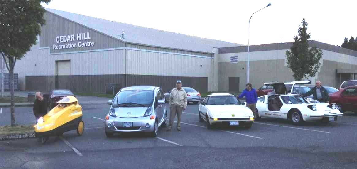
On the second (band
having not yet started up for the season) I went to the VEVA Islands
electric car club. One member had purchased a 1981 Bradley electric.
I'm sure I saw the Bradley in Popular Mechanics magazine way
back then. The "gull wing" doors were supposed to be great in crowded
parking lots. Another had brought his lightweight velomobile - which
has pedals but zips along the street at 50 Km/Hr under electric power.
We posed them along
with
my RX7 and a Mitsubishi iMiEV owned by a retired electrician.
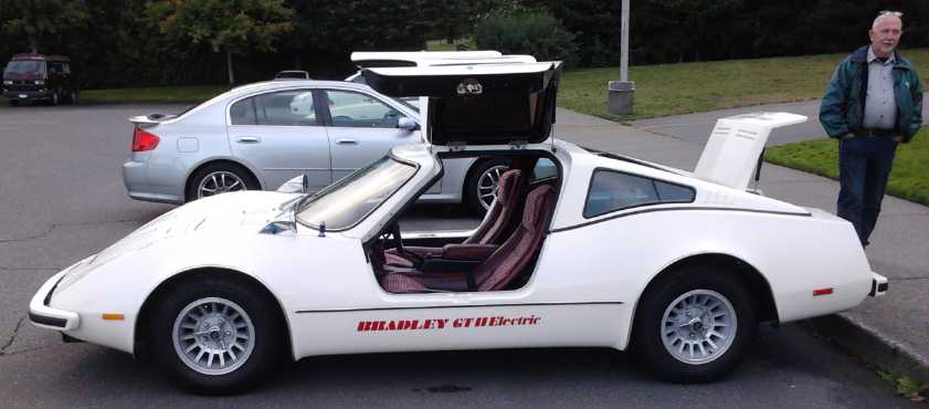 The 1981 Bradley Electric (the only one ever
made in Canada) with its
proud owner.
The 1981 Bradley Electric (the only one ever
made in Canada) with its
proud owner.
The body is in great shape. Is it because it's fiberglass, or because
it spent 20 of its 34 years sitting in a garage?
(Of course if I was doing this now, I'd use polypropylene ("landscaping
fabric") with resin - It's tough; stronger &
lighter than fiberglass, and nice to work with. A good paint should
prevent degradation of the plastic by sunlight.
In fact, that could be a fabulous way to reduce vehicle weight, and
thus of course increase driving range!
...Make a whole car body?!? Yikes! Don't get ideas, Craig!)
In practice the Bradley's interesting gull wing door
design made it hard to get in and out of the car, and it's easy to see
why it never caught on. The unadjustable semi-reclined bucket seats
didn't help either.
On the third I decided to make the planned solar water
heater into a pumped system after all. Other than pump and controls,
the logistics are simpler. The pre-heat water tank and a system that
drains down when the pump shuts off can't freeze and burst. I ended up
buying more pipe for this, but didn't get any actual work done on it.
An 18.5V "power adapter" lithium battery charger in the
Mazda RX7 EV quit. On
the trip where I noticed it, the voltage of the whole pack was already
down to 12 volts - at my destination point, where I noticed it as I got
in
the car - and to nothing by the time I got home. They should never be
allowed to drop below 14.0 volts, 2.8 volts per (3.2V nominal) cell.
The drop was very rapid and luckily it was only short trip, about a
mile. It didn't seem to hurt them.
I soldered a plug back on the 17 volt transformer type
adapter I had first bought for them. It had worked well enough, but it
eventually brings the voltage up to 22 volts, when the cells should
never be allowed to rise above 20. A 15 volt adapter might stay under
20 volts, but then it might charge to 16.5 volts very slowly. This
shows the problems with unregulated supplies. OTOH the "17 volts" can
be down under 15 when charging a low battery without a series resistor
yet without overloading the transformer - a bit of 'constant current'
operation, or
say a sliding scale of current versus voltage. At one point I had tried
to put in a 19 volt zener diode to stop it from going higher, but it
got hot very fast. I guess I should buy a new 18.5 V regulated adapter
- ug! Or maybe I'll try a "15" or "16" volt transformer type. Or add
some diodes to drop the voltage a bit.
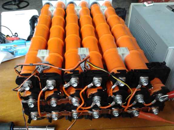 Later the
Bradley owner was given, and then gave to me, a Honda
Insight hybrid (or hybrid Civic) battery: 120 high rate D cells
providing 144 volts in series. I converted its strings of 12 cells to
parallel, 14.4 volts, thinking to use it in the Mazda RX7 EV. But my
enthusiasm waned: I found out on line that the cells were only 6.5
amp-hours for a total of 65 amp-hours. And it weighed 55 pounds - as
heavy as lead-acid. (extra metal and less chemicals, to get the very
high rate performance.) It should perform well and last for ages, but
with only 65% of
the capacity of the other batteries it would likely further limit the
already short driving range. Perhaps it could be a 28.8 volt, 33
amp-hour, 'spare' battery for the electric outboard? Then I found
another 6 tubes of 14.4 volts on ebay for (by the time I get them)
probably around 325$C. That makes over 100 amp-hours.
Later the
Bradley owner was given, and then gave to me, a Honda
Insight hybrid (or hybrid Civic) battery: 120 high rate D cells
providing 144 volts in series. I converted its strings of 12 cells to
parallel, 14.4 volts, thinking to use it in the Mazda RX7 EV. But my
enthusiasm waned: I found out on line that the cells were only 6.5
amp-hours for a total of 65 amp-hours. And it weighed 55 pounds - as
heavy as lead-acid. (extra metal and less chemicals, to get the very
high rate performance.) It should perform well and last for ages, but
with only 65% of
the capacity of the other batteries it would likely further limit the
already short driving range. Perhaps it could be a 28.8 volt, 33
amp-hour, 'spare' battery for the electric outboard? Then I found
another 6 tubes of 14.4 volts on ebay for (by the time I get them)
probably around 325$C. That makes over 100 amp-hours.
Then I got three 12.8v, 40 AH lithium batteries for 600$
locally. It was just too good a deal to pass up. I initially got them
for someone else who was to pay me back, but then it looked like he
couldn't use them. If I put everything together right, I may not need
any golf cart batteries for a 300 AH, 36V vehicle drive system. Instead
I can probably use two 300 AH, 12 v (or 14.4 v) batteries of NiMH D
cells and one of 12 v worth of lithiums in parallel. That would
certainly lighten the car, allow regenerative braking, and of course
last longest.
And apparently I bid on an auction for another 5 tubes of
12 Honda batteries, because on October 2nd I got a notice from e-bay
that I had won the bid, for 99¢. At first I thought I must have
made some mistake and bid on empty plastic tubes or something. Nope,
they were batteries. No one else had bid! The shipping was also 99, but
with the decimal point on the other side. Still, it was 5 more tubes,
60 cells, for 1/2 the price of the first 6 and 1/4 the price of new
Tenergy cells. From the original 10 free sets I'll be up to 21 - total
252 high rate NiMH D cells and about 500$C.
 I did more
peltier cooling experiments. I put a 14 or 15 amp peltier module
(62x62mm) into the shallow chest fridge and tried running it at some
lower voltages with the lab power supply. Obviously the cold from the
peltier wasn't being transferred well into the ice tray, so I soon
found and put in a new ice tray, a little shallow but much larger and
made of thick (cast?) aluminum instead of stamped from thin pressed
sheet metal. It worked much better, but the ice still formed from the
cooling bar end, and the inner end never froze over. Then I needed the
power supply for other things and I put the fridge back on the solar
panels, with the battery charger taking the load at night. It was
getting quite cold underneath and around the ice tray, as low as
2.5°c, but it was still over 15° at the far wall near the top.
I added a small 12V "computer" fan (with some resistors in-line to keep
it to a whisper and a light breeze). It took days for the stuffed-full
warm end to cool, but eventually it was all under about 8° or so at
the warm end and 5.5° under the ice tray - much better overall
cooling. But it was using 130 watts during the day. When I find the
time, I should make the microcontroller based control, with (along with
various features) a DC to DC converter in it to supply a lower voltage
to the peltier for a higher COP. It gets that at night when the battery
charger takes the load - and the voltage drops to 11 volts (with the
peltier still drawing almost 8 amps), and the fridge temperatures in
the morning are no higher than in the day (if not lower) when it's up
over 13 volts and 9.6 amps.
I did more
peltier cooling experiments. I put a 14 or 15 amp peltier module
(62x62mm) into the shallow chest fridge and tried running it at some
lower voltages with the lab power supply. Obviously the cold from the
peltier wasn't being transferred well into the ice tray, so I soon
found and put in a new ice tray, a little shallow but much larger and
made of thick (cast?) aluminum instead of stamped from thin pressed
sheet metal. It worked much better, but the ice still formed from the
cooling bar end, and the inner end never froze over. Then I needed the
power supply for other things and I put the fridge back on the solar
panels, with the battery charger taking the load at night. It was
getting quite cold underneath and around the ice tray, as low as
2.5°c, but it was still over 15° at the far wall near the top.
I added a small 12V "computer" fan (with some resistors in-line to keep
it to a whisper and a light breeze). It took days for the stuffed-full
warm end to cool, but eventually it was all under about 8° or so at
the warm end and 5.5° under the ice tray - much better overall
cooling. But it was using 130 watts during the day. When I find the
time, I should make the microcontroller based control, with (along with
various features) a DC to DC converter in it to supply a lower voltage
to the peltier for a higher COP. It gets that at night when the battery
charger takes the load - and the voltage drops to 11 volts (with the
peltier still drawing almost 8 amps), and the fridge temperatures in
the morning are no higher than in the day (if not lower) when it's up
over 13 volts and 9.6 amps.
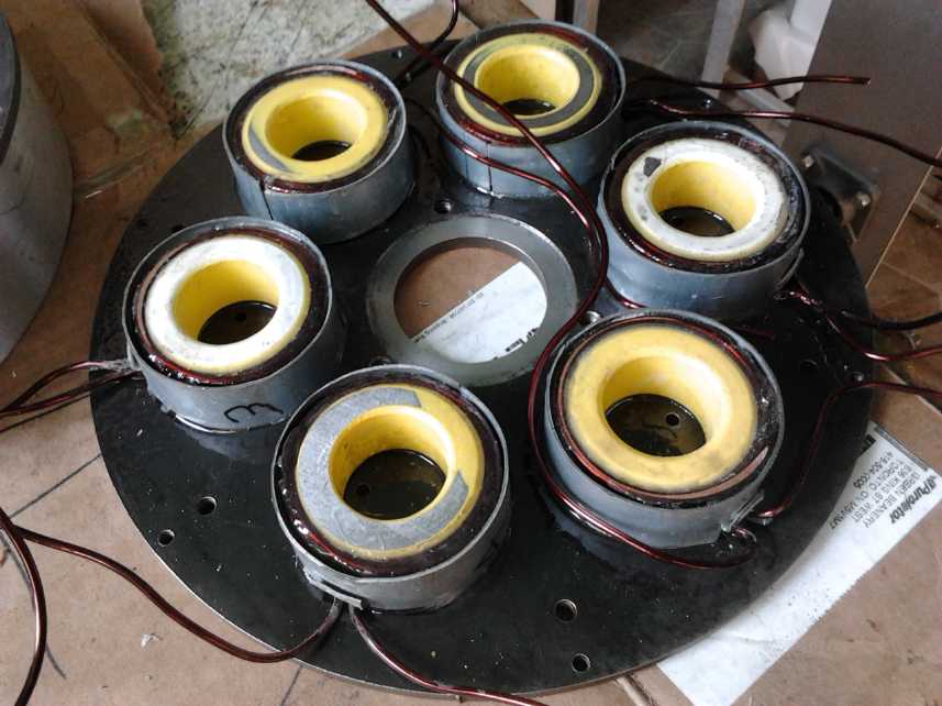 I trimmed and
epoxied the steel rings onto the ARM motor coils to make them into "cup
electromagnets", and epoxied the coils onto the bottom plate. And I
welded the rotor to its hub. Then I designed and made a small circuit
board for the optical interrupters that tell the controller where the
rotor rotation is at. I had meant to check to make sure there were no
shorts of the coil windings to the case before the epoxy was hard - too
late! There was one. I didn't manage to break the coil loose with a
hammer and a wooden block, but finally I unwrapped a bit of the coil
wire and the short vanished. At least the episode showed the coils were
very solidly glued onto the bottom plate by the epoxy. Then I did the
heavy wiring, and found the fat wires simply wouldn't fit as intended
into the case. It was too cramped. I finally unscrewed the cable clamp
from the case and let the cable hang out. Every time there was a
problem I would set the project aside for a couple of days. I had
trouble concentrating on it. It wasn't until near the end of the month
I checked out the optics board. It had a problem too - wrong
connections from a mirror image defined optical interrupter part. I cut
traces and added wires to get it to work, then fixed the design on the
computer.
I trimmed and
epoxied the steel rings onto the ARM motor coils to make them into "cup
electromagnets", and epoxied the coils onto the bottom plate. And I
welded the rotor to its hub. Then I designed and made a small circuit
board for the optical interrupters that tell the controller where the
rotor rotation is at. I had meant to check to make sure there were no
shorts of the coil windings to the case before the epoxy was hard - too
late! There was one. I didn't manage to break the coil loose with a
hammer and a wooden block, but finally I unwrapped a bit of the coil
wire and the short vanished. At least the episode showed the coils were
very solidly glued onto the bottom plate by the epoxy. Then I did the
heavy wiring, and found the fat wires simply wouldn't fit as intended
into the case. It was too cramped. I finally unscrewed the cable clamp
from the case and let the cable hang out. Every time there was a
problem I would set the project aside for a couple of days. I had
trouble concentrating on it. It wasn't until near the end of the month
I checked out the optics board. It had a problem too - wrong
connections from a mirror image defined optical interrupter part. I cut
traces and added wires to get it to work, then fixed the design on the
computer.
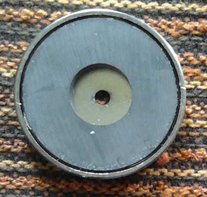 A regular cup magnet. The flux is concentrated
in
A regular cup magnet. The flux is concentrated
in
the gap between the magnet and the outer ring,
providing supermagnet levels of strength in that small gap.
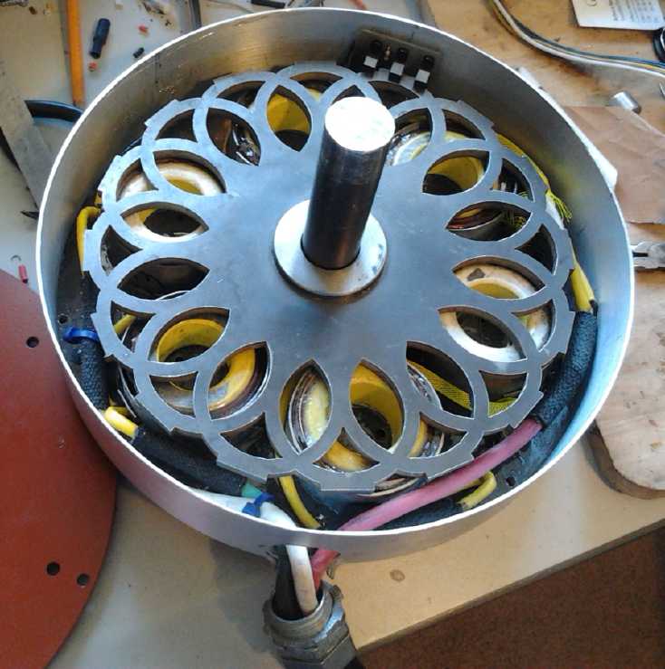
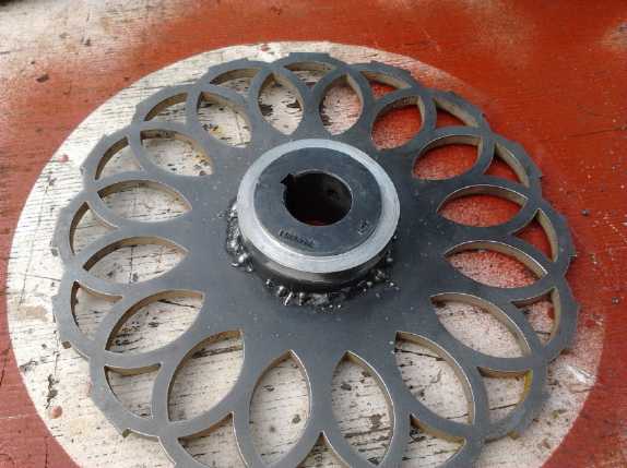
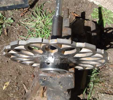
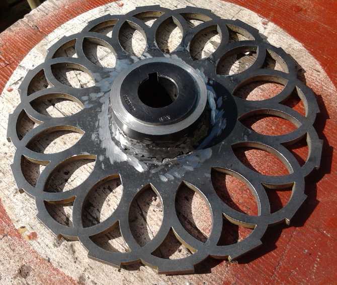 The rotor with overlapping rings that match the
stator's "cup electromagnet" rings.
The rotor with overlapping rings that match the
stator's "cup electromagnet" rings.
Besides the flowery shape, the other unique feature is in having many
rotor "poles", 8, per each 3 phase coils, instead of 2.
This places each ring quite close to the stator electromagnet rings as
each phase is activated, for highest torque.
Instead of switching once per electrical revolution, each coil switches
8 times - 16 times per physical revolution.
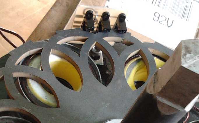
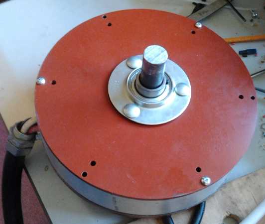 ARM Motor more or less Assembled
Short video: https://youtu.be/cifPWF1Snr0
--
ARM
Motor Running (top cover off)
On the 29th I hooked it up to the motor controller and ran
it with the top off. It started promptly and ran quite nicely in both
directions except for the rotor rubbing a bit in one spot (which was
worse with the top on), but I won't vouch for performance or
efficiency. The optics adjustment was more critical than it should have
been owing to the thin little light interrupter tabs on the outside of
the rotor. They really should have been wider, and rounded on the
outside. There seemed to be a lot of torque ripple, and not all phases
had the same strength - again perhaps an optics problem, because it
changed after adjustment from one stronger phase to two out of three.
If the motor was to be produced the torque ripple might be reduced by
adjusting the thickness of the rotor rings, probably by increasing the
outer diameters a little. But I'm more keen on trying out the highly
promising 'transverse flux' design than making more of this style.
Running it disclosed some issues with the unipolar motor
controller which need to be looked at. Nothing quit or went up in
smoke, but the energy return coil got smoking hot. Much of the energy
seemed to be going into heating it up! I started thinking that there
wasn't enough current flowing in the wires to explain it. Was my
simplified controller design wrong? But the pulses to it are very
sharp, and I remembered that iron cores are only good for low
frequencies, up to a few hundred hertz, not 20 or more kilohertz with a
high harmonic content. I may need to make a coil with a ferrite core.
And the motor would only go up to a couple of hundred RPM. It seemed to
go from zero to drawing 11 amps in a very short space on the rotary
control, but turning the control up further, even all the way to the
top, had little or no further effect on current and speed. Wasn't this
supposed to be a 200 amp controller?
Towards the end of the month I started looking up 'free
energy' devices again. I'm not sure anything else in the sustainable
energy field would be quite so valuable. There was an interesting
electrostatic "Perpetual Motion Motor" video. I don't think I've seen
anything using that sort of motive force before. https://www.youtube.com/watch?v=dGPnxLSgnUI
It turned, but the motive force was so slight I couldn't imagine trying
to scale it up to get useful power from it.
Somewhere I found someone who actually seemed to know
quite a bit about magnet propulsion, youtube channel "MotionMagnetics".
He went into three types of magnet motive force machines in three
videos. He mentioned that things were very exacting, and that magnets
weren't identical. Small variations in the magnetization of each magnet
would make a machine work or not work, probably explaining why no one
has successfully produced them for sale after making a working
prototype. I heard of an attempt where this happened. He didn't get
into the easier to make hybrid types where the machines self-propel
around the loop with permanent magnets except at the one inevitable
"sticky spot", where an electromagnet or mechanical device assists it
past. The electromagnet is said to use less energy than is generated in
the rest of the loop.
But my main target was "lambda ray collectors", which I
searched on as "radiant energy receivers". After a week of this puzzle,
I finally figured that Tesla, Moray and others probably hadn't captured
lambda rays, radiant energy, at all - at least not directly. Most
likely they had captured the static electrical charge of the
atmosphere. Air has an electric charge that increases rapidly with
altitude, amazingly up to 100 volts more positive per meter on a clear
day. Lightning discharges clearly demonstrate the existence of airborne
ionic energy. But some lesser amount of electrical potential energy
must be present in the air when there is no lightning. In fact, people
have been electrocuted by the static charge on unconnected power lines,
and a long steel cable strung from a helicopter makes a huge spark when
it touches ground. Is this what was being harvested, and can it be done
again effectively with today's technologies? Moray made special
germanium semiconductors (the world's first semiconductor devices) and
special vacuum tubes that would be hard to duplicate, but other things
might work in their place.
A passive circuit with antenna, ground, capacitors and
diodes will gradually build up a few volts and supply a few milliwatts,
but it isn't very effective. You want kilowatts (or at least watts);
you want to run your house, but it will only gradually charge a
cellphone. (I made one in 2013 - TE News #68. With the antennas I tried
it only got up to a volt or so and imperceptible power.)
It appears that the successful people, in particular
Moray, made tuned circuits with a driver - oscillators - and actively
pulled the energy, literally, out of thin air with resonant circuits.
Instead of getting a few charged ions that randomly drift by the
antenna, they are actively pulled and pushed in tune with the
oscillations, vastly increasing the interaction of the antenna with the
air. There probably are some lambda ray energy receiver types of energy
devices, but famous(?) powerful 'free energy' devices like Moray's
might well instead be atmospheric charge harvesters. Some puzzling
things about these various energy devices started to make more sense to
me.
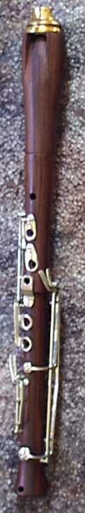 For the past
year and a half I had been playing in the Greater Victoria Concert Band
"junior band" with my Supercorder. The conductor liked the sound and it
had been well received. It was a small band when I first joined and I
was well heard. But this season I tried the "intermediate band" to play
some more challenging music. It seemed to me to be going well but on
the 30th out of the blue I was asked to leave. Apparently the conductor
and one or more of the flute players didn't appreciate the fine tonal
and expressive qualities of my instrument (which have earned me many
compliments) because it didn't sound the same as a flute. It wasn't
quite what their ears were familiar with. Well - their loss!
For the past
year and a half I had been playing in the Greater Victoria Concert Band
"junior band" with my Supercorder. The conductor liked the sound and it
had been well received. It was a small band when I first joined and I
was well heard. But this season I tried the "intermediate band" to play
some more challenging music. It seemed to me to be going well but on
the 30th out of the blue I was asked to leave. Apparently the conductor
and one or more of the flute players didn't appreciate the fine tonal
and expressive qualities of my instrument (which have earned me many
compliments) because it didn't sound the same as a flute. It wasn't
quite what their ears were familiar with. Well - their loss!
I know some like it. One flautist had seemed glad to hear
I would be there, and one who was elderly sitting beside me (and
perhaps having a hard time sightreading some tricky rhythms) had just
the previous week told me "You're a treasure! You're right on and the
sound is clear and easy to follow."
Even in music it seems successful adoption of inventions
has a lot to do with timing. Sax was too late to have his creations
adopted into orchestras, whose instrumentation had by then become more
or less "standardized", but new types of bands were springing into
existence, and the saxophone came to be standard fare in some of those,
including in the large concert band - pretty much an orchestra
of wind and brass instruments with considerable percussion. (...itself
perhaps a timely invention of JP Sousa?) I suppose if Sax had invented
them today they'd be quite unwelcome there. There would be no parts
written for them and the unfamiliar sound would probably be considered
crass. If on the other hand he had made them 50 or 100 years earlier
than he did, they might well have become mainstay orchestra
instruments. (and perhaps clarinets would have been dropped?)
Likewise, if the recorder had had my improvements by
perhaps by 1850 instead of 2006, it just might have been the transverse
flute that would be considered "airy" sounding and "parochial", and
might have been left "unmodernized".
The earlier part of the day
had gone better. Having borrowed a surplus tunable air core coil and a
tuning capacitor the day before, I picked up books on LC oscillator and
HF transmitter design for the atmospheric charge energy harvester and
(bonus!) an evacuated tube heatsink module that I can try out with the
peltier camping cooler. And my vacuum jar for one of the steps in
making the ethylene glycol/choline chloride DES battery electrolyte
arrived by post.
In Passing
(Miscellaneous topics, editorial comments & opinionated rants)
A Perspective on the Syrian Crisis
It's hard to form an informed opinion on what's been
happening in Syria from the occasional disconnected reports with no
background context in the western media, which give no overall view.
Until refugees started flooding into Europe recently, virtually no
mention was made that over 1/2 the entire population had been driven
from their homes by war and bombing, with towns, utilities and
industries reduced to rubble over the past 4 or 5 years.
Listening to Syrian Girl, who has been occasionally reporting
from Syria
on the events and politics for some time now, may broaden your
perspective, if not change your views considerably.
https://www.youtube.com/watch?v=pHFnvFbThDE
- Syrian girl
NO MORE WARS!
Loose Change
I asked in a coin shop how much old (Canadian) silver
quarters were worth. These were made from 80% silver and 20% copper
from 1920 to 1967. (The alloy was harder than pure silver and
so the coins lasted longer.) I found out that a dollar as coins had .6
troy ounces of silver, regardless of denomination. Thus a silver dollar
had .6 ozt, a 50¢ piece .3, a quarter .15, and a dime .06 ozt. (A
troy ounce, or Trojan ounce as I like to call it, because somehow it
seems
sneaky, contrived), is about 31.1 grams, where the "real" Avoirdupois
ounce is 28.something grams.)
Virtually unrelated: It has been found that an alloy of silver and
germanium makes a "sterling silver" that doesn't tarnish. (The patent
has probably expired.) This might have made better coins for
circulation!
The price for any and all of this change was thus
denominated as the price per face value dollar, ie per .6 ozt of actual
silver content. At that store it was 13.50$. This is a good indication
of how far inflation has gone. In 1920 the silver content of the coins
would have been pretty much a token amount. Coins were probably also
the main form of exchange, since prices of most small items were in
pennies. Paper bills were for large purchases. (Even in 1960 kid's bus
tickets in Edmonton were 6 for a quarter - 4-1/6¢ each.) By 1967,
Canada's 100th
birthday, the face value of each coin had become worth less than this
"token amount" of silver. Oodles of US and Canadian silver coins were
melted down for their silver value. An old quarter or dime in change
has been a very rare sight for decades now.
Today four "nothing special" silver quarters or ten dimes
- change for a looney - will cost you 13.50$ or more to buy. So
the dollar is now worth only 7% of what it was worth in 1967. And since
2011 the price of silver has been manipulated down with "high frequency
trading" of huge,
uncoverable "naked shorts" (banks selling silver they don't have on the
futures market) to make the dollar look better, dropping from
over 40 US$/ozt to under 12. The 2011 high price would indicate today's
dollar is under 2.5% of what it was in 1967. In 2011 silver may have
been
overvalued. It is certainly undervalued today. The best guess is
somewhere in the middle, that the dollar is worth 3 or 4% of what it
was in 1967.
Backed by nothing and printed as notes or simply conjured
into existence on banks' computer screens ad infinitum, the whole
world's fiat currency is headed for zero. It is not necessarily that
fiat
currency can't work, but that those in control of the supply have
always
opted to print more, gradually transferring the value of peoples'
savings to themselves as new tho decreasingly valuable money, rather
than face budgetary restrictions. Every fiat currency in history has
ended up being worth zero.
Silver on the contrary is a tangible asset, whose value
may fluctuate in accordance with supply, demand and sometimes market
manipulation, but which owing to limited (and presently declining)
mining supply and electronic device market demand on top of investment
demand, can never fall too much...
unless some fantastic
new silver deposits are discovered or "cold fusion" can be used to
create far more. (That would be fabulous, since it's about 12% more
conductive than copper for making motor coils - the most conductive of
all elements by size. But the chances seem remote.) It will therefore
tend over time to at least stay even with inflation, rising in dollar
price as the value
of paper money falls. Silver and gold have thus long been viewed as
"safe havens" for storage of wealth, especially in volatile times, and
this is better understood over much of the world than it is in the west
after our long period of relative stability and prosperity.
As I write, the supplies of silver and gold seem
to be running short. Month after month there is new record demand from
Asia
and from a million small investors who wish to cash in their claim
checks on wealth (dollars) for things outside the banking system that
won't inflate away and can't be confiscated with "bail-ins" and
"capital controls" (where you can only withdraw a very limited amount
of your dollars each day), as is starting to happen here and there. The
CEO of Sunshine Mint, a main coin blank supplier to the US
Mint, said in an interview
that shortages so far are owing to production time to stamp out the
record demand for coins and bars (they're running 24/7 and have tripled
their production capacity since 2007), but he also said that they are
now pulling
old silver ingots out from the backs of their vaults, and that it takes
weeks
to get more in instead of a day.
At some point everybody will catch on
and there'll be a run. If you don't go to a coin shop or go online and
get some 'soon', when that run starts there won't be any at any
affordable price. (with no known date on 'soon' - maybe within weeks
but
quite possibly months, or even a year or two.)
Some day there will be no more money. World population
will be controlled by common consent (2 to 3 billion?), and everyone
will have what they need for a good quality of life with free time to
learn and grow. Instead of being
permitted to earn a certain amount, people - everyone - will be
permitted to have a certain amount of possessions and supplies
for their
personal use. No one will be permitted to hoard unreasonable amounts of
goods which would result in scarcities for others. There won't be a
small clique commanding most of the resources, and natural resources
will be considered common property. The whole mentality will be more
social - less "me first!", more "consideration for all but without
neglecting me, too." Since everyone will be permitted to
own reasonably similar amounts, and since those amounts are sufficient
for all to live a good life, all will agree to this system. Those whose
talent and enterprise provide large social benefit will be permitted
somewhat more than the average - perhaps 3 or 4 or more times as much
as the "poorest" or basic allotment: the
'profit motive' or reward is not to be discarded. But no one will have
a hundred, thousands or a million times as much as most others.
Everyone will do
perhaps 3 or 4 hours work per day to maintain this sustainable social
system, and then fill their days with more creative or spiritual
pursuits or pastimes. It will probably take a thousand years to get
there, but in the
million year march of human history... that's 'soon'.
Perpetual War
Someone made this list of countries the USA government and
or its "corporatocracy" and or it's military-industrial-financial
complex has struggled with, covertly or overtly interfering in its
affairs through the military or various government or "private"
agencies, since world war two. I don't vouch for its accuracy - some of
the dates given seem arguable. And I don't know what the asterisks are
for. (Probably this is just a copy of a list that originally gave some
context.) Ten years of peace might transform the face of the USA if it
allows that to happen - and perhaps the face of some beleaguered
countries where "regime change" keeps getting instituted!
China 1949 to early 1960s
Albania 1949-53
East Germany 1950s
Iran 1953 *
Guatemala 1954 *
Costa Rica mid-1950s
Syria 1956-7
Egypt 1957
Indonesia1957-8
British Guiana 1953-64 *
Iraq 1963 *
North Vietnam 1945-73
Cambodia 1955-70 *
Laos 1958 *, 1959 *, 1960 *
Ecuador 1960-63 *
Congo 1960 *
France 1965
Brazil 1962-64 *
Dominican Republic 1963 *
Cuba 1959 to present
Bolivia 1964 *
Indonesia 1965 *
Ghana 1966 *
Chile 1964-73 *
Greece 1967 *
Costa Rica 1970-71
Bolivia 1971 *
Australia 1973-75 *
Angola 1975, 1980s
Zaire 1975
Portugal 1974-76 *
Jamaica 1976-80 *
Chad 1981-82 *
Grenada 1983 *
South Yemen 1982-84
Fiji 1987 *
Libya 1980s
Nicaragua 1981-90 *
Panama 1989 *
Bulgaria 1990 *
Albania 1991 *
Iraq 1991
Afghanistan 1980s *
Somalia 1993
Yugoslavia 1999-2000 *
Ecuador 2000 *
Afghanistan 2001 *
Venezuela 2002 *
Iraq 2003 *
Haiti 2004 *
Somalia 2007 to present
Honduras 2009
Libya 2011 *
Syria 2012
Ukraine 2014
NO MORE WARS!
Advantages of hard assets for
wealth retention when things crash - from 2002 after the 'dot com
bubble' collapse (Author unknown)
: If you had bought $1000.00 worth of Nortel stock one year ago, it
would
: now be worth $49.00.
:
: With Enron, you would have $16.50 of the original $1,000.00.
:
: With Worldcom, you would have less than $5.00 left.
:
: If you had bought $1,000.00 worth of Lone Star Beer (the beer, not the
: stock) one year ago, drank all the beer, then turned in the cans for
the
: 10 cent deposit, you would have $214.00.
:
: Based on the above, my current investment advice is to drink heavily
and
: recycle.
Caught Red Handed!
Since the US government has withdrawn the border guards and left the
Mexican border wide open, citizen militia have started patrolling the
border. One group chased down and stopped an SUV with two men that had
come across. It was full of cocaine. The men pulled out CIA employee ID
cards. But officials at the Cocaine Importing Agency, the world's
largest and oldest drug running group, denied any association with the
vehicle and men.
Prime Minister's "Famous" Great-Great Uncle (and black is white and
white is black! Received in an e-mail.)
Judy Harper, an amateur genealogy researcher in Northern Ontario, was
doing some personal work on her own family tree. She discovered that
Prime Minister Stephen Harper's great-great uncle, Remus Rudd, was
hanged for horse stealing and train robbery in Winnipeg in 1889. Both
Judy and Stephen Harper share this common ancestor.
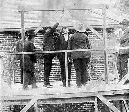 The only known photograph
of Remus shows him
The only known photograph
of Remus shows him
standing on the gallows at the Manitoba Provincial Jail.
On the back of the picture Judy obtained during her research
is this inscription:
'Remus Rudd horse thief, sent to Stony Mountain Jail 1885,
escaped 1887, robbed the CP AND CN trains six times.
Caught by Mounted Police Force, convicted and hanged in 1889.'
So Judy recently e-mailed Prime Minister
Harper for information about their great-great uncle, Remus Rudd.
Believe it or not, Harper's staff sent back the following biographical
sketch for her genealogy research:
"Remus Rudd was famous in Ontario during the mid to late 1800s. His
business empire grew to include acquisition of valuable equestrian
assets and intimate dealings with the CP and CN Railways..
Beginning in 1883, he devoted several years of his life to government
service, finally taking leave to resume his dealings with the railroads.
In 1887, he was a key player in a vital investigation run by the Mounted
Police Force. In 1889, Remus passed away during an important civic
function held in his honour when the platform upon which he was standing
collapsed."
NOW That's how it's done, Folks! That's a real POLITICAL SPIN!
(Author unknown. Hmm, I'm sure I've seen that before somewhere... where
some "notable"(?) died tragically in some apparently freak accident
"when the platform he was standing on collapsed" at some public
function.)
 I only caught the last half of the reportedly
excellent total eclipse of the moon,
I only caught the last half of the reportedly
excellent total eclipse of the moon,
but the next night there were some really interesting clouds lit up by
the moon.
The photo does them little justice. Below are lights across the bay
reflected in the water.
Newsletters Index/Highlights: http://www.TurquoiseEnergy.com/news/index.html
Construction Manuals and information:
- Electric Hubcap Family Motors - Turquoise Motor Controllers
- Preliminary Ni-Mn, Ni-Ni Battery Making book
Products Catalog:
- Electric Hubcap 7.2 KW BLDC Pancake Motor Kit
- Electric
Caik 4.8 KW BLDC Pancake Motor Kit
- NiMH Handy Battery Sticks, 12v battery trays & Dry
Cells (cheapest NiMH
prices in Victoria BC)
- LED Light Fixtures
- CAT 12 volt DC plugs, sockets, wall receptacle plates...
(Will accept BITCOIN digital currency)
...all at: http://www.TurquoiseEnergy.com/
(orders: e-mail craig@saers.com)
Daily
Log
(time accounting, mainly for CRA - SR & ED assessment purposes)
September 1: Worked on August newsletter
2: Finished and posted it.
3: -
4: Started voltage versus cooling experiment in 12V thermoelectric
fridge. ARM motor - Epoxied steel rings around coils. (Got 2 chickens.
1 egg first day, 2 the next, 0 for a day then 2 more... Hmm, chickens
eat a lot more than fish. Then no more at all after the first dozen.
Laying shut off like a switch, both birds! ...Roast chicken next
perhaps?)
5: ARM - Trimmed sheet metal rings and sanded coils to a semblance of
flat
and even. Epoxied them to motor base plate.
6: Touched up epoxy job. Designed circuit board for rotor position
sensor optics.
7: Printed out, laminated, etched, drilled and populated circuit board
for motor. Made an "L" bracket mount for it. Wire brushed top and base
and painted them with urethane spray paint.
8: Mounted and tried to adjust board so optical sensors didn't hit
rotor. Rotor wasn't quite flush -- it hit both top and bottom during a
rotation. Welded rotor to hub. Two tries. (That didn't help the
flushness.)
9: Tried to adjust rotor alignment with minimal success. Made cable for
rotor position sensor (triple optical interrupter) board.
10: Populated PCB for LED light and restored first LED grow light to
operation. (It still runs too hot!)
11: Made a video about (world's most?) water conserving shower nozzle,
the Waltec 10C, which uses less than 1/2 the water of any other "water
conserving" shower nozzle. (How about a good shower with 5 or 4 or 3
liters per minute?) It appears to be long out of production. It should
be brought back! Or re-invented.
12: Wired the pairs of coils together. Tested and found a coil was
shorted to the case. Ouch! (Rats! -- I meant to check for that while
the epoxy was still soft!) Installed 14 amp peltier module in
thermoelectric fridge. (Also see 15th, 17th, 23rd. Voltage trials went
on a few days.)
13: Tested to find which coil of two. Attempted to remove coil. I might
have to smash it to pieces. Changed Peltier Module on solar fridge to
large size 15 amp unit and started cooling tests.
14: A few Peltier fridge temperature measurements. (Heat transfer to
ice tray is poor.)
15: Bought rectangular aluminum pan with thick bottom & sides,
hoping it would make a better ice tray for the thermoelectric fridge.
Repaired shorted motor coil.
16: -
17: Installed the tray.
18: Did the heavy wiring in the motor - it doesn't fit - can't close
the case.
19: Pulled the connector off the case and pulled the wires out a bit.
Just fits! With the case closed, the rotor rubs at least a bit
somewhere, but I'll try it out as is.
20-26th: Studying "free energy receiver" circuits and writings.
23 (& on): Placed small fan to blow air in Peltier 12 V fridge.
Trials continued into October. Major improvement in overall cooling.
27: Tested motor optics. Optical interrupter part had mirror image
LED.s. Sigh! Cut and soldered wires to get board working, redesigned
part & PCB. At last discerned that the "free energy" as collected
by Tesla, Moray and others actually does come out of thin air. Air has
increasing charge with altitude, and their oscillating devices could
apparently collect that energy far more effectively than the passive
"cell phone charger" system with only diodes and capacitors.
28: Designed a tentative schematic for capturing air energy charge.
29: Got reluctance motor running. (YAY!) Filed off a coil ring where
the rotor was rubbing. (It would work better if the rotor was dead flat
and straight!) Did a revised air energy charge harvester schematic and
picked up a tunable coil and tuning capacitor for air charge energy
device.
30: Tried a few more things with reluctance motor. Obtained some books
on oscillators and radio transmitter design, and (bonus!) a vacuum pipe
heat dissipator intended for computer CPU.s, but just the right size
for a typical 40x40mm peltier module. (I'll try that with the camping
cooler some time, seeing the new peltier in the thermoelectric fridge
is 62x62mm.)
Electric Hubcap Motor Systems - Electric Transport
ARM Motor
The ARM (Axial flux switched Reluctance Motor)
On the 4th I did my best to
adjust the steel rings I made and rolled up (now months ago) for the
ARM motor coils to turn them into "cup electromagnets", and I epoxied
them onto the coils. There was lots of trimming to do before the coils
were anything like flat and the right height. Much as I feared,
attaining the exacting dimensions for .025" flux gaps is virtually
beyond my ability for largely hand-made assembly with epoxied wires and
curved sheet metal parts. So the gaps will be larger and hence the
specs not as good as might otherwise be expected. There will have to be
some major assembly simplifications and quality improvements to the
process if this motor is to be produced. (The transverse flux design
seems more promising.)
On the 5th I trimmed the rings with tinsnips and then
carefully sanded them, then painted on some more epoxy (a couple of the
rings were loose at the end) and let it set. In the evening I numbered
the coils and positions and ground out dips in the base plate in places
on 3 coils where where flattening them had sand them down to bare wires
in spots. That should keep them from shorting to the plate.
I had decided
simply to epoxy the coils onto the steel bottom
plate, and then build up the epoxy a layer or two, and maybe a little
polypropylene cloth, for strength. This is safer than simply epoxying
magnets to a rotor, since the stator doesn't spin - there's no
centrifugal forces and it doesn't have to be balanced. The
day-and-a-half old epoxy (kept in the freezer to prevent rapid setting)
seemed rather thick, so I just painted one more layer on when the first
coat had set.
Motor Base with "Cup Electromagnet" Coils
Next came the optical rotor position sensing system. I
thought the 3 optical interrupter sensors had to be placed at 60 or
120° intervals around the outside edge. That's how I did it with
the magnet sensors. That precluded putting them on a single circuit
board. In fact, the available space was a little cramped and they would
have to be mounted at an angle instead of straight on. That would keep
them inside the outer case ring so I didn't have to cut holes at 3
exact spots and then line it up accurately, and also let them miss the
case assembly bolts using existing holes.
Then it occurred to me that with 8 overlapping rings per 3
coils, the interrupters could be much closer together -- in any three
positions where they lined up in a proper 3-phase spacing to the rings,
which were about 42mm spacing, so at 0, 14 and 28mm. Perhaps I could
drill one or two new
holes and mount an assembly with the three interrupters? When I
checked, it looked like that would work.
I measured about 1.65" from one ring to the next at the
outside, so 2/3 of that would be 1.1", with the 1/3 position at .55".
(which is, sure enough, 14mm)
It looked like the board should be about 1.75" tall to mount with a
small "L" bracket from the bottom plate and hold the 3 interrupters.
(LED + Phototransistor pairs facing each other in a housing with a
5/16" gap between them - ordered from somewhere on aliexpress.com).
Make it 1.4" wide to cover the 1.1" plus connection wires plus margins.
There was the basis for a PCB design. Making a PCB seemed the best way
to go. I've developed an aversion to "cludged-in" component
constructions.
I designed it on the 6th, then printed, 'laminated' it,
etched it, drilled it, and populated it on the 7th. And made an "L"
bracket mounting to hold it u to the rotor. I managed to forget to
print it mirror image on the first try, but I decided to do a couple of
flat panel LED light boards at the same time, and the reversed
lettering on them prompted my memory before I etched it. I then
proceeded to print it out the right way around... on the back side of
the
toner transfer paper. I didn't notice until the paper wouldn't release.
I patiently soaked it off, worked it up and used it anyway. The board
came out with a
few paper fibers (which I had tried to rub off) shorting close
gaps at the optical interrupter modules, seen (by 60 year old me) only
under a magnifying glass. I scraped them away with an exacto knife.
There were "micro-pits" in the copper everywhere, but all the
connections seemed good.
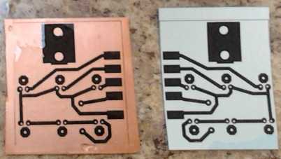
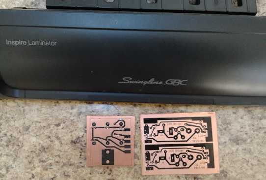 Mirror image board - Motor optics and LED light
boards ready to etch
Mirror image board - Motor optics and LED light
boards ready to etch
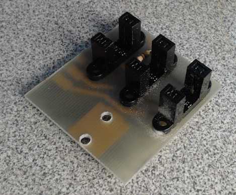 Finished (except for wires/cable) Board
 Optics in Motor (Light from behind shows copper
traces through PC board)
Optics in Motor (Light from behind shows copper
traces through PC board)
( EAGLE PCB Files: Schematic , Board , Optical Interrupter "lbr" -
corrected but untested as drawn )
(The 5/16" optical interrupters were from somewhere on aliexpress.com )
On the 8th I got out the little MIG welder and welded the
rotor to its hub. I'm definitely no pro welder. Someone feared it might
break off at high RPM. I hadn't yet put the welder away, so I went out
again and added lots more equally ugly
weld. The poor carpenter blames his tools, but I suspect the cheap, 120
volt welder is too light for these heavy pieces. But then personally
I'm not sure I'd do any better with the old 230V stick welder either.
Then I ground off the ugliest bumps with the angle grinder and it
didn't look so bad.
 First and Second so-called Weldings.
The second one looked somewhat better after some grinding to smooth it.
Is that the trick?
 Then I went to try and true up the run, to eliminate the
wobble, by bending the rotor plate just a fraction. It grazed the
bottom of the optical interrupters at one point of rotation, and the
top 1/2 way around from there. I spent a lot of time without
accomplishing much. It would be off at different points each time I
tried bending it. The next day I checked again. I found I had bent up
an actual bump, a raised area, to add to the problem. I went out to the
big vise and pushed - one more time after so many - hoping to bend out
the bump. Miraculously I did, and the whole alignment was virtually
perfect all the way around. Wow! Quit while ahead!
Then I went to try and true up the run, to eliminate the
wobble, by bending the rotor plate just a fraction. It grazed the
bottom of the optical interrupters at one point of rotation, and the
top 1/2 way around from there. I spent a lot of time without
accomplishing much. It would be off at different points each time I
tried bending it. The next day I checked again. I found I had bent up
an actual bump, a raised area, to add to the problem. I went out to the
big vise and pushed - one more time after so many - hoping to bend out
the bump. Miraculously I did, and the whole alignment was virtually
perfect all the way around. Wow! Quit while ahead!
On thinking about it, it's possible there was some speck
of grit between the two upper rings of the thrust bearing (I added the
second ring to increase the clearance), and that that rather than the
rotor caused the wobble, with the 'random' bad alignment rotations. (I
did casually wipe them off once, but without apparent effect.)
After a lot of work drilling and filing holes in the "L"
bracket and much adjusting, I found that the optics assembly
had to be removed to install or remove the rotor, and then needed
realignment. And the head of the bottom bolt was inaccessible until the
upper one was removed, and the upper one had a nut, hard to reach, that
made it hard to loosen and tighten for adjustments. It occurred to me
that if the
bracket was threaded so the bolts were put in in the other direction it
would all be much simpler. Easier to do it now than after further
frustrations and possibly breaking something. I replaced the hardware
store "L" bracket with a new one made out of 16 gauge nickel-brass --
with holes that were where I wanted them, and threaded. (As I gave it a
final sanding, I lost my grip and it shot out the back of the bench
belt sander and fell behind the bench, never to be seen again. I
finally
gave up looking and made another one.)
With the rotor straight and a bracket that would stay
where it was positioned to, the rotor spun true in the gap between the
optical elements. But some imp must have come along and bent it again
while I wasn't looking, as it ran crooked again later. (Or was it just
a fleck dust somewhere... or more likely, a fleck dust the time it ran
straight?)
On the 12th I wired the pairs of coils in series. Then,
belatedly, it occurred to me to make sure no coil wires were short
circuited to the bottom plate. I had intended to do this while the
epoxy wasn't set yet, but had forgotten. Now there was a penalty for
that omission: there was indeed a short, and the coils were solidly
epoxied to the bottom plate and the pairs were wired together. In order
to identify the coil, I ran a 1.0
amp current through the offending pair, and checked the voltages to the
plate to see which end was closest to the plate. One end definitely was
closest, the
coil I'd marked "5". I pried off the outer ring of the coil, and
scraped away as much epoxy from around the base as I could. But
hammering it via a block of wood wouldn't budge it. It looked like I'd
have to smash it to get it off. I set it aside for a couple of days.
Perhaps an inspiration might come?
It did. I thought to unwrap just the outer bottom winding.
Maybe that would make take away enough epoxy grip that I could knock it
loose? But when I started, I only unwound a couple of inches, then
thought to check again. The short was gone! It must have been right
there at the start of the coil... or else it had been shorted to the
outer ring. (Maybe I hadn't needed to do anything but remove that?) I
scraped the stuck epoxy off the ring, mixed a very tiny new batch, and
epoxied it back on. I put a heavy weight on it hoping to
keep it down below the rotor while it set. By night the epoxy was hard
- and there was no short. The rotor spun freely again after I filed off
the epoxy and metal ring inevitably sticking up a bit. Well, that was
certainly easier than breaking off the coil and making and installing a
whole new one! The three days lost were of course fully occupied by
other things.'
At least the episode demonstrated that simply epoxying the
coils on held them quite well. And the current test for the short
incidentally disclosed that the DC resistance of each phase was about
30 milliohms. That's 1/2 the resistance it would be if the phases were
used in "Y" configuration, going across two phases instead of having
each phase tied to B+. As I recall, the Electric Hubcap motors of the
"standard" BLDC configuration with #11 wire coils were about 67
milliohms. This should result in overall copper losses being quite
similar, notwithstanding that only one phase is energized at a time
instead of two, and so (all else being equal, which it surely won't be
anyway) more current will probably be required to attain the same
magnetic force.
I started studying free energy devices rather intensively
(along with getting more batteries and doing various things that needed
doing) and it wasn't until the 27th that I hooked up the motor optics
to the controller and tested it. It turned out that the LED.s were
defined backwards in the part "library", so it didn't work. I cut
traces and put in wires to make the connections, then fixed up the part
and board designs. Once corrected, the unit seemed to operate just
right. (The little tabs I put on the outside of the rotor were quite
thin, and I had been afraid one or two of the outputs would be blocked
too much or too little and wouldn't change state at the right times.
Once the motor was running this did prove to be the case and
adjustments were required.)
On the 29th I bought some connectors to put on the ends of
the heavy wires, hooked it up, and (after 5 tries out of 6 possible
ways to connect the 3 wires) the motor ran. It seemed to use too much
current to spin with no load, but it got up to about 195 RPM with 10
amps at 30 volts. Soon I disconnected the lab supply which only goes to
10 amps and hooked up 24V of NiMH D cells in two 12V tubes.
But turning the control up higher seemed to have no effect
- only about 12 amps of current was drawn, and the speed didn't rise.
There was only a small area on the rotary control where the motor went
from zero to this maximum. This is probably mainly a controller issue.
I hadn't turned up the BLDC 4:3 motor above about 10 amps because I
just ran it on the 10 amp lab supply (and it got up to good RPMs with
that), probably explaining why I hadn't run into it before. After a
time the coil got smoking hot, and the energy return diodes were also
pretty hot. The switching mosfets were only slightly warm, and the
motor was hardly warm. Before, I thought that it just needed to be a
bigger coil with heavier wire. Now it occurred to me (again, as with
the free energy device coil and frequency) that the frequency of the
switching, and especially the sharp switch-off pulse spikes, was
probably too high for an iron [iron powder] core. Surely it needed to
be ferrite or something. Definitely much of the power was going into
heating up the coil, not running the motor.
I found there was a lot of torque ripple by holding the
rotor back, allowing it to slowly rotate. In some spots it could be
easily held, but it would jump through some others with far higher
force. I could see as I was putting things together it wasn't going to
achieve even torque, the "phase ON" start position being farther from
coil alignment than I expected from the cardboard trials. I still think
this can be evened out by adjusting dimensions, even if the weaker
areas are only increased at the expense of the maximum torque.
When I went to check the actual levels of torque, I
discovered the shaft I had used had no keyslot to attach the device. So
I've left it for now.
One phase seemed to have substantially more torque than
the other two. This was a puzzle since the coils were all the same.
Then I loosened a screw on the optics board so I could move it around a
bit. Side to side made little difference, but moving it in and out
changed things markedly. Moved out, the motor stopped entirely. Moved
in, the RPM appeared to about double, still with the same 11 amps
current. Of course the middle phase interrupter was slightly closer in
than the other two, with the flat circuit board not quite matching the
curved rotor. Presumably it was full strength while the other two were
getting light prematurely and switching at the wrong times. But I
adjusted the optics to a new position and was still getting higher
currents and torques for two phases than for the third. The whole thing
still has some puzzling features, including that the interrupter
frequency shown as a number on the oscilloscope sometimes seemed
different at the same RPM (perhaps was a harmonic) - and didn't match
the actual waveform seen. Later all three phases seemed to have the
same strength.
Since I've already found a better design I don't plan to
make any more of this motors. On the other hand, by running this one I
might learn some more about reluctance motors and about my own
implementations of them in particular before making the next one. And
the motor controller, which I hope to use for any and all of my future
transport-size motors, definitely needs at least some "tuning up" in
the coil - and the synchronous rectifier drivers, and it definitely
doesn't run this motor as well as the BLDC4:3 type, so the interactions
need study.
"Transverse
Flux" Motor
A probably better
way of using the "hole saw" drum came to me watching a video of a
commercial reluctance motor. The outer rim of the drum is only 1/16"
thick or so.
Instead of attaching the "horseshoe magnet shorting bars" across the
outside face, they could be attached on the inside. With the thin metal
elsewhere, that would provide enough of a difference that it should
work pretty well. Anyway that seemed to be how the commercial one was
done.
That would be a big relief from a design standpoint,
because if the 'bars' are on the outside, the diameter for designing
the stator would depend on the thickness of the bars. The bar thickness
would be critical and at the same time might easily vary owing to
welding or soldering variances, and any change in thickness would mean
redesigning and rebuilding the stator. On the inside, slight variances
won't affect the dimensions and the flux gaps. I can now start
designing the stator for the drum's exact outer diameter, without
fearing
that diameter will need changing at a whim.
With each bar resting at the drum's bottom, they should be
easy to silver solder on - they won't try and shift or fall off. Or
maybe I can just epoxy them on?
Other
"Green"
Electric
Equipment Projects
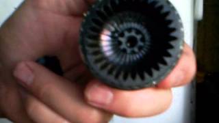
Water
Conservation: Best Shower Nozzles and Video
I have what appears to be a "well kept secret", or rather
a piece of useful knowledge that just never spread: shower nozzles
capable of delivering a fair spray with under 3 liters of water per
minute, and a good stiff spray with 4 or 5. Well, maybe 6. A so-called
"water
conserving" shower nozzle is considered to be one that uses 9 liters
per minute, so this is 1/2 the water usage.
It happened that I bought a "Waltec" bathtub faucet set in
about 1980 or 81 (or even earlier?) in bathroom renovations. The
faucets and spout were
nothing special, but the shower nozzle I would call "clearly
superior". Instead of having the water come out around the edge
and through "watering can" holes here and there, it all comes out
sideways behind the adjustment knob from a central point, spraying into
curved triangular grooves that spread it out and aim it down, and not
all the same (which would form a single ring of water) but with varied
ejection angles.
I soon went out to the same plumbing store and bought
another one for the other shower, specifically asking for that same
part number, a "Waltec 10C shower nozzle" (IIRC the number), and one
was produced from the back of the store. The clerk even seemed familiar
with that specific number without looking it up - something someone
else had asked for? I've never seen anything like it before or since,
in spite of looking at shower nozzles in stores on several occasions.
"Better mouse traps" seem to often be invented and then go out
of production and are forgotten, for reasons that seemingly have
nothing
to do with performance. Whenever I shower away from home, such as at a
public shower (pool or campground), I'm aghast at how much water gushes
out, yet often with a rather feeble spray - such a waste of energy and
water! Surely they could do better in showers that are in use all day
every day!
But no. As far as I can find, they haven't been available
for decades, and there's nothing else like them. I think the original
mold and design needs to be found and returned to use, or it needs to
be be reinvented.
 The
nozzle
originally made a soft spray with a minimum of
about 4 liters of water per minute. I added a final touch: a small
rubber washer around the adjustment knob, the same diameter as the
knob. By closing the adjustment down just a bit more, the start of the
already small grooves is closed a bit more by the rubber and the most
water conserving operation mentioned above is possible, still with good
spray.
The
nozzle
originally made a soft spray with a minimum of
about 4 liters of water per minute. I added a final touch: a small
rubber washer around the adjustment knob, the same diameter as the
knob. By closing the adjustment down just a bit more, the start of the
already small grooves is closed a bit more by the rubber and the most
water conserving operation mentioned above is possible, still with good
spray.
I must add here that some people don't like it and open
the adjustment wide to get "typical" higher water usage. That too can
be accommodated. But I can hear that they just open the taps wide open
to start, and then of course the spray is much too hard when they pull
the shower knob. They haven't figured out that a good but water
conserving shower requires setting the water initially to a pretty low
level. (These same people also don't pay my water or power bills.) It
would no doubt help if faucets were made that make it easy to make
small adjustments to the flow. (I think those single knob bathtub
faucets that don't adjust at all - full blast or nothing - are the acme
of a bad idea!) Or perhaps reducing the water supply would make the
adjustment range of the taps finer. As it is, when I budge the cold tap
just a smidgen (...did I actually turn it, or not?), the temperature
goes between too cool and too hot. The hot tap has somewhat better
range, if only because my hot water isn't turned up too high.
Another factor is simply what people are used to and what
they expect. If one is expecting a huge gush of water, a strong, finer
spray probably seems weird, and people may start adjusting to get
something more familiar, more in line with expectations, without
critical examination of what might actually be better.
I started out by deciding to do a video about water
conservation quite a while ago, and then to cover the shower nozzles
specifically. I still haven't posted the first one, but here is the URL
for the shower nozzle one: https://www.youtube.com/watch?v=Qs6iKSch2sI
.
Peltier Module / Thermoelectric Cooling Experiments
As voltage on a Peltier module is increased, so is the
current, so the power consumption is related more to the voltage
squared than to the
linear increase. The fridge has been using a 15V, 8.5 amp rated
module, which values yield 128 watts. But the calculations aren't so
simple because the current drops as the temperature difference rises
between the hot and cold side. The
experiment with changing voltages on the 12V solar fridge showed that
there was considerably more cooling at 9 volts than at 8, and at 10
volts than 9, slight gain going
from 10 volts to 11, just a little from raising that to 12, and
apparently none
going up from 12 to 13 volts. 14 volts seemed, if anything,
slightly worse than 13.
And it turned out that the voltages at the peltier itself
were notably lower than at the power plug, with some resistance in the
wires and connections. I had been content to use the volt meter on the
power
supply, while realizing that there would be a little more drop across
the wires and the control relay before the peltier modules. When I
returned the supply to the solar panels I belatedly measured the solar
voltage at the socket (13.4 volts), and then at the leeds of the
peltier module/TEC ('thermo-electric cooler') itself. It was only 11.6
volts - a 1.8 volt drop! That meant that my results were skewed -
that the voltages I was comparing were actually 10-15% lower than
what the meter said. (Also that I should be using heavier wires... or
long, light wires to get to a desired lower voltage!)
Another unreliable figure is the interior temperature: the fridge is in
use, mostly for canned milk for coffee and mixed nuts and things (plus
cool storage for many items that are rarely used). Every time the lid
is opened, the temperature rises perhaps 1/2 a degree, and it takes
some time to return to the pre-opening figure. Plus if a warm item is
placed near the sensor it warms up the vicinity. I present the
table below derived from 2 pages of measured figures over 6 days from
Sept. 3rd to 9th, and later (9th, 10th) measured
real voltages at the TEC's input leeds for the given supply
voltages, and otherwise cleaned up and estimated,
with various similar readings averaged out.
When (2015/09/--)
|
Volts (at actual Peltier
module connections)
|
Amps
|
Power
(TEC actual)
|
Room°
|
Fridge°
(Cold end)
|
Notes
|
/03 - 9:00 AM
|
11.8 v (solar, at plug)
(~10.3 v at peltier)
|
-
|
-
|
-
|
6.0
|
Initial reading. Then set to 8.0
volts (at power supply!) at 9:30
|
- 11:20
|
7.3 v
|
3.0 a
|
22 w
|
20.0°
|
8.1°
|
warming. Ice in ice tray melting.
Set to 9.0 volts after readings.
|
- 15:00
|
8.0 v
|
3.7 a
|
30 w
|
20.0°
|
6.6°
|
Ice still melting.
Set to 10.0 volts after readings.
|
- 24:00
|
8.8 v
|
4.1 a
|
36 w
|
21°
|
6.5°
|
Melting of ice much slowed.
Set to 11.0v after readings.
|
/04 - 9:00
|
9.7 v
|
4.5 a
|
44 w
|
20.5°
|
6.1°
|
More ice (still < 1/2 tray)
Set to 12.0v at 18:40 PM
|
- 21:30
|
10.6 v
|
5.0 a
|
53 w
|
21°
|
6.0°
|
More ice - headed for 1/2 tray.
Set to 13.0v next day at 15:30.
|
/05 - 15:30 to
/06 - 9:00
|
11.6 v
|
5.4 a
|
63 w
|
21.5°
|
6.3°
|
A bit more ice. (note > room°)
Set to 14.0v, /08 at 8:45 AM.
|
/08 - 12:15
|
12.5 v (est)
|
5.9 a
|
74 w
|
23°
|
6.5
|
Temperature not dropping
(but room temp higher)
|
Referring to the table, the 8 volt setting (delivering
just
7.3v to the TEC, <50% of its rating) was obviously not
doing enough cooling and I raised it a volt to 9 after about 2-1/2
hours.
That, delivering 8.0 volts to the module, still had the ice tray
gradually
melting, and I raised it another volt to 10 (8.8v at peltier) after
3-1/2 hours. That reduced the melting speed to a crawl and I left it
there 9 hours, but it was still a warming trend. At 11 volts (9.7 at
peltier) more ice started to form. 12 volts was a small improvement,
but going to 13 (still only 11.6 at the TEC) seemed to make minimal
difference. I did some more readings at 11 volts on the 6th to 8th. The
room temperature had risen with warm weather, as high as 24°. The
fridge warmed up by a somewhat lesser amount, mostly under about
7.0°.
On the 8th I tried 14 volts (~12.5v at the module) just
for completeness. As expected, it seemed to be little better, if at
all. The heatsink and fan work too hard to dissipate 74 watts of input
heat energy plus about 40-45 watts of heat transferred from the cold
side, so the warm side temperature gets much warmer than room
temperature, raising the temperature differential the heat has to be
pumped across. Going to the higher levels was just wasting energy and
worse, probably was a major contributor - if not the main contributor -
to shortening the lifetimes of the modules.
The next thing to try was to install the big 14 amp
peltier module, 62x62mm, that I got from somewhere on AliExpress.com
(TEC12715...
maybe it's 15 amps?). That could
certainly be run at lower voltages (8 to 9v?) and hence in a more
efficient
range, to presumably deliver the same cooling using lower power. Or
(9 to 11v?) substantially more cooling at the same power.
Perhaps it could even get
the whole fridge nice and cold. Then I could put in a fan to blow the
air
around for even all-round cooling. It might even allow the intended
operation mode of turning the fridge mostly off at night (or whenever
the 12 volt supply voltage was lower) and doing extra cooling during
the day (whenever the supply voltage is higher indicating the batteries
are charging), ideally freezing the whole ice tray while the energy was
coming straight from the solar panels (or other periodic power source
[wind?]).
I installed it on the 12th. When I started to disassemble
the old setup I found it had made lots of ice overnight and the fridge
was surprisingly (after the temperatures in the above table) under
5°c. Power would have been at about 11v
overnight and then 13.5v during the morning. The only thing that seemed
to account for it was less opening of the lid.
I also found that the switch was hot and also some of the
connectors. I got rid of it all - switch, Chinese control unit with
relay, and some skinny wires - and left just the plug, cord, fan and
connectors for the peltier. If it's plugged in, it's on. (One skinny
wire remained.) And I discovered that it was a little harder to change
the Peltier module than expected: the copper bar didn't stick out far
enough to hold the 62x62mm square. However, I had at one point
previously fitted it, and there were threaded holes in the right places
to do it. I had to thaw out and remove the ice tray to change it, so I
put fresh water in it. And the lid was open a long time. Obviously it
would take a day or so to settle in before ice extent and temperature
readings would mean much.
When everything was together I set the power supply to 9.0
volts (at 15:00 PM), and it was using 6.4 amps. At the Peltier leeds it
was 8.4v. That made 54 watts actually reaching the TEC, about
equivalent in input power to the 12 volt setting on the old unit. I
also got out an actual ampmeter and compared it to the power supply's
meter. It seems that in this middle range at least, the power supply's
meter is pretty close. In the lower ranges (eg, under 3 amps) it reads
low by about 10%, and I applied this factor, evidently in error, to the
amp readings. I adjusted those and the resulting watt figures in the
table - or should I say I un-adjusted the erroneously adjusted readings?
The bottom and outer end of the copper cooling bar were
exposed to
room air. With it sticking out farther, there was no hollow space to
hold a piece of foam insulation on. They soon frosted up. I cut a sort
of an "L" piece and pinned it to other insulation with a couple of
nails. Less than satisfactory! And considering the water was still
+6°C, it didn't say much for the heat transfer from the bar to the
aluminum 'bread pan' ice tray. I think that was a problem the previous
time I tried to fit the big TEC and moved the tray bolts to the very
end of the bar.
After a couple of hours, things didn't seem to be cooling
in any hurry, so I upped the voltage to 10.0, which brought the current
up to 7.0 amps. 70 watts! Like the first time I tried this big module,
I got the impression the heat wasn't getting transferred very well.
Even at 9 volts, the heatsink seemed too warm. Of course, there was
less contact area of the tray to the copper bar. And the clamp wasn't
centered on this large peltier module. Later I turned it back down to 9
volts. The temperature seemed to settle out at a little over
6°. After another day I set it back to 8 volts. It very gradually
(~36 hours) went up to about 7° and most of the ice melted. Yet the
copper bar was covered by thick frost.
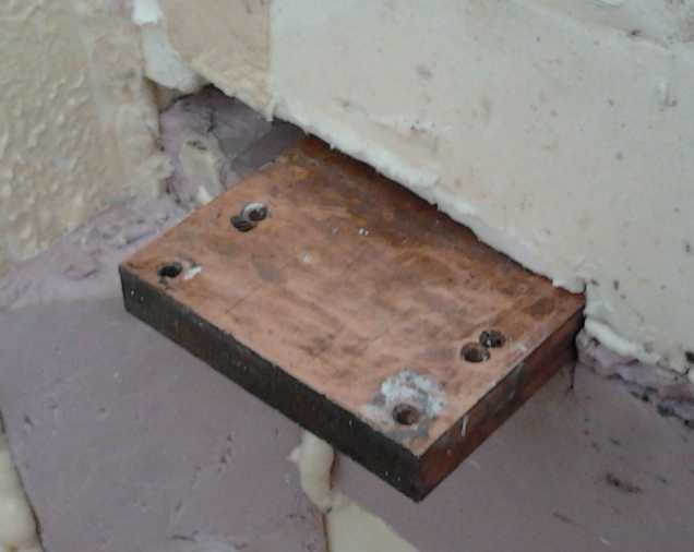
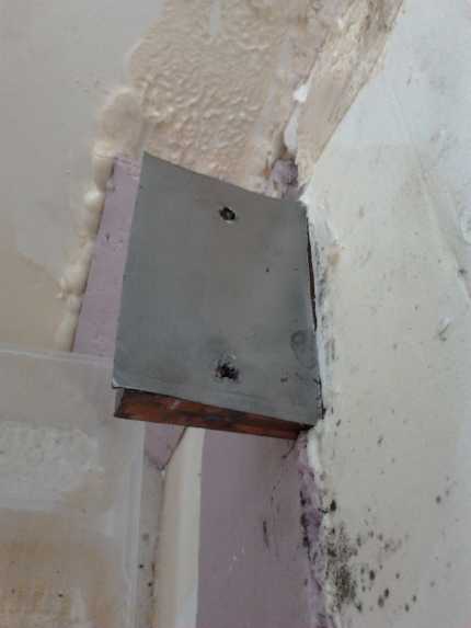 (L) Reduced end of copper cooling bar inside
fridge after moving it out 22mm to accommodate larger peltier module.
(L) Reduced end of copper cooling bar inside
fridge after moving it out 22mm to accommodate larger peltier module.
(R) with flexible graphite to fill gaps and transfer heat better to the
ice tray. (An alternative to silicone heatsink compound.)
Surely a major problem was the lack of contact surface of
the ice tray to the copper bar. The bar was covered with frost well
before ice started forming in the tray. If the heat transfer was
better, the bar wouldn't get so cold before cooling the tray, or hold
so much frost while the tray melted. I started thinking maybe I should
solder together a copper ice tray with a thick bottom. Or maybe I could
find an aluminum pot with a thick bottom that would transfer cold from
the bar better than the thin aluminum bread pan. A thick walled pot
shaped
like a breadpan would be ideal!
The next
morning (15th) I went to "Value Village" to see
if there was any such rectangular pan. There was one, much bigger than
my bread pan ideal and shallower, but close enough - easier than trying
to make something out of copper. I bought it. On the 16th I put it on.
The first benefit proved to be the straight vertical sides of this
tray. I could use the original bolt holes in the cold bar instead of
the 'extras' I had had to put in almost at the end to hold the sloping
bread pan with the larger peltier module. That would provide more heat
transfer surface.
I set the supply to just 8.0v, drawing 5.7 amps - about 45
watts. As it was new tap water and the fridge had been open while I was
working, it wasn't initially very cold. After an hour or so (at 13:30
PM) the approximate temperatures read: Cold bar under Peltier: 2°c.
Cold bar inside fridge under tray: 4°. Water directly above in tray
base: 6°. Water at far end of tray: 12°. Fridge below cooler:
11.3°. Room temperature: 23°. It seemed to be cooling quite
rapidly, and in 10 minutes those figures were: 0,4,5,11,11.0 and
23°. The heatsink warmest area was just 26°, and I turned down
the fan, which was somewhat annoying. (It's hard to get much accuracy
with a temperature probe giving no decimal units and touching a
thermocouple to
somewhere on a surface with poorer to better contact. The probe that
reads to a decimal point takes several minutes to reach temperature.)
The small temperature differences between the cold bar and
the water right above it were encouraging. So was the fact that the
water at the far end of the big tray was following them down nicely.
But 8v is only 1/2 of 15. I turned it up to 8.5v at 14:15. And 9.0
before bed. It seemed to be on the verge of making ice, but none
formed. The next day I needed the power supply to charge some
batteries, so I plugged it into the solar power system. It was cloudy
and the high load brought the system down to 12.5 volts (instead of
14.0) with about 12 volts delivered to the fridge. But there soon was
ice. The module draws enough current that at night the system voltage,
fed by a battery charger, droped to about 10.4 volts (delivering a
little under 10 volts to the fridge), where it was previously about
11.7. (Later when the inside was cold and everything settled down it
stayed around 11° and 8 amps (88 watts) at night.) At night and in
heavy overcast the low voltage alarm goes off on
the inverter (which I charge the RX7 EV through on sunny days) and I
have to shut it off. During the day the current measured 9.6 amps,
using 134 nominal watts at 14 volts.
So the fridge experiments are morphing into designing a DC
to DC buck converter (see below) to reduce the supply voltage and hence
power to this big peltier, which also, as previously discussed several
time, increases the COP and thus has virtually the same cooling power
using less supply power.
It's hard to compare the old and new tray performance
directly. The
new tray is much larger, so it radiates more, doubtless cooling the
whole fridge more - more even cooling. So a higher inside temperature
at the floor near the tray doesn't mean it's cooling less overall. But
after a few days, with room temperatures around 21-22°, there were
generally cooler temperatures through larger portions of the fridge.
There was lots of frost buildup on the cooling bar and under the ice
tray at the cold end, where there was considerable ice in the tray -
eventually about 1/2 the tray. I suspect the end of the copper cold bar
within the frost was -3 to -5.
Right in the back corner at the bottom under the ice tray it got as low
as 2.3°, elsewhere under the tray was 3 to 5, and 4.5 to 6 in the
area around the tray at the floor, but rising with altitude toward the
top. The temperatures there don't rise as much after
opening the lid as before, eg .2° instead of .5°, which
seems to indicate that it rises more from stirring of the internal air
than
from introduction of outside air, and that colder air was now more
generally widespread. In the middle half way up I got readings of about
7 to 10°. At the far wall past a bunch of stuff blocking the most
of the cold air coming from the cold end, at the top, it was still just
"cooler than outside" at 16.5°, but seemed to be down a degree or
so from before. Of course, any small fan blowing inside would even out
the temperature considerably. I should probably put one in -- along
with the DC to DC converter and a programmable control for solar and
wind - for intermittent power.
I pulled a small 'computer' fan from the closet on the
evening of the 23rd, and connected the wires to a CAT plug (with a
couple of resistors to reduce it from a hurricane to a breeze and a
whizzing hornets' nest to a whisper). Then I simply set it in
the fridge in a corner blowing air at the cooling tray, and plugged it
into the 12V solar power outlet with a short CAT extension cord coming
out the edge of the lid. That's not exactly 'installed', but it blows
the air around. If it can warm up the cold bar to near zero and melt
some of the ice, the cooling will gain COP by working across a smaller
temperature differential, and the whole average temperature inside the
fridge will be cooler than without it.
After 24 hours, there was considerably less ice in the
tray, and the temperatures near the tray were mostly over 5°. But
everywhere else was cooler, with anywhere the middle around 7°
instead of up to 10, and the warmest areas towards the far end near the
top being around 9 to 11° instead of 15+. It seemed more like a
real fridge. With the air blowing across it, the frost on the cooling
bar had turned to hard ice, and it probably wasn't as cold.
There was a huge tub of margarine occupying much of the
far end, a big heat mass which I thought would probably cool some more
in the next day or two and make for further temperature drop at the
warm end. But the next morning I found that the rest of the ice in the
tray (which had seemed pretty much constant all day) had melted and the
coldest temperature under it was up to 5.3°. And most of the ice
was gone off the cooling bar. Apparently this was all using up the
accumulated coldness as well as the cooling capacity of the system.
then again, I suddenly remembered I had also turned the outside fan
down for less noise. Could that have made such a difference to the
cooling? I put it up to full. A little ice formed right where the
cooling bar meets the ice tray, but no more. The difference from the
fan seemed to be there, but small. Some days of trying things disclosed
that if the inside fan was set somewhere where it moved just a bit of
air, everything could be made to a good compromise. Under the ice tray
readings were 6-7°c but only the very far wall was over 10, at
about 11°. Even upper areas near the far wall were 8-9°. And
about 1/2 the ice tray stayed frozen. This of course is with using the
14 amp peltier at max all day on solar, with the voltage dropping under
11 at night.
Temperature measurements with the fan at different
settings (positions) continued into October. Overall result: The
coldest section near the ice tray got a little warmer, but within a
week the warmer areas in general became much cooler, with the whole
fridge staying between 5 and 8° - a great overall improvement in
cooling! A control on the fan would be an asset.
As usual I have other things to do besides design the
MSP430 microcontroller control to make peltier voltage and all
programmable with the inside fan coming on and off, and I'll be putting
it off for yet another month.
However, there was one more interesting development. On
the 30th I got a heatsink with evacuated tubes just somewhat along the
lines of what I had tried to make, sized for a 40x40mm peltier module.
Since the fridge's new peltier is too big for it, I'll try it out in
the camping cooler. And I have the vacuum pump... maybe with that I can
successfully make my own evacuated heat transfer pipes, for which
sufficient vacuum has so far eluded me.
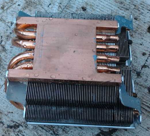
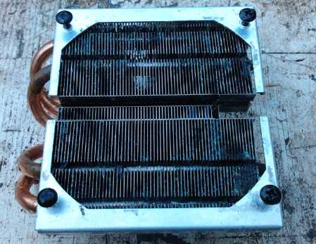 Evacuated Tubes Heatsink. These carry heat away
even faster than solid copper.
Evacuated Tubes Heatsink. These carry heat away
even faster than solid copper.
The copper plate on the bottom is ideally sized for common 40x40mm
Peltier modules.
The water turns to steam (even at room temperature) as the plate warms,
and rises up the tubes in the plate to the radiator fins above.
A small computer fan cools the radiator fins.
The cooled water re-condenses and drips back down the tubes.
DC to DC
Converter
It became more and more evident that various projects
needed a DC to DC converter, namely a buck converter to reduce voltage
in a more efficient way than a linear voltage regulator. Whereas I
hoped only for efficiency of 80+%, I reviewed a paper on DC to DC
converters that mentioned as high as 94% could be attained with
synchronous rectification. Naturally I would jump at the chance to make
the project more complicated -- I mean, to make a better design.
After spending a
good part of a couple of days looking up circuits, making one and
starting in on a board design, I thought that if I was firstly doing a
converter for the solar fridge, and if the solar fridge needed a
microcontroller control, I might as well make the converter with the
microcontroller and a minimum of other necessary components.
Essentially, it would be the fridge control circuit that I'd already
designed on paper
but never made, with the addition of a driver, coil and a
few sundry extras, voltage feedback to the microcontroller, and having
the program rapidly turn the peltier drive on and off to keep it near
the desired voltage.
Electricity
Generation
Electrostatic Perpetual Motion
Motor?
I saw a video on this by "Nikola Tesla" on youtube.
Operation was apparently by electrostatic forces - there were no
magnets. Unlike most people, his machine appeared to spin by itself,
seemingly wherever and whenever,
and he explained how it worked. He made the point that the force was
very tiny, and it managed to run because it had tiny "needles" to spin
on (very low friction) and the rotor was very well balanced, a
precision "scientific instrument". I won't try to explain it all here
as he does
a pretty good job in the short video -- and I can't say I understand it
myself because he did leave out explaining a couple of things that may
be well known in some circles, but not by me.
It looked like a pretty easy thing to build and try out.
But it would have to be precisely constructed. And even if it would run
reliably, it would obviously take a considerable number of big rotors
to generate even a few watts. That would still be farther than I've got
so far in this realm.
https://www.youtube.com/watch?v=dGPnxLSgnUI
- Perpetual Motion Machine
Then there was another video by someone else that showed
"how it was really done". He had built a crude
copy of the original machine. Let's see now... it turns on a #10(?)
threaded rod with no taper, no bearings, resting on pieces of wood at
each end. That already violated the original poster's 'very low
friction' requirement and would probably keep it from turning. Then the
rotor wasn't balanced - no no #2. Then their electrical charge "points"
were the rounded heads of two pan head machine screws: some "points"!
Then to demonstrate that it would eventually stop, he spun it by hand
-- in the wrong direction. Well, he seemed to have demonstrated that his
build didn't work!
But then there was an irony: he then hooked up a vandegraf
generator and he had his young son (standing on an insulator) touch the
ball on top of the generator and put his finger (the other hand) next
to the aluminum bits on the rotor, in lieu of the two metal points. The
rotor turned! (And in the right direction.) "Well, unless somebody has
a better explanation, I think this is how he did it!"
Wow! Far from "debunking" the idea, they had shown
that a sufficient electrostatic charge will in fact turn the rotor --
just like the original guy said! The high charge of the vandegraf
generator turned even their high friction, off balance unit, with just
a blunt finger for a point.
The point about the electrostatic points and charges
focussing at such points is reminiscent of pointed crystals or pointed
pieces of gold or copper apparently used in
lambda ray collectors ("free energy devices"), but I'm not sure what
the actual connection is.
One youtube video leads to another and I ran across
someone called motionmagnetics who seemed to have a very good
grip on 'perpetual motion' magnet machines. He said there were three
types, and he had a video explaining each of them. I was impressed with
how precise things needed to be, and how inevitable small differences
in the magnetization of each magnet could throw everything off, and how
someone could have a working prototype and yet be unable to make a
reliable - or even working - production model. Compared to that, the
electrostatic machine seemed really simple and easy to do.
Still, one would think a design where key magnet positions
could be minutely adjustable could be worked out. Failing that, a
design such as a spiral or helix that is easy to get working except
where the spiral starts and ends could be made using an electromagnet,
or a solenoid moving a magnet or magnetic shield, to carry it past that
position. Motionmagnetics said he wasn't going to cover such hybrid
designs.
Electricity
Collectors... Energy From Where?
I also did a little
reading on Thomas Henry Moray and his
1925-1929 'radiant energy receiver', hoping to better figure out how
one might
be made. Vital details for how to make such radiant energy receivers or
collectors always seem to be
frustratingly missing, whether because the invention was a deception,
by lack of understanding of why their own devices worked, energy
company or other corporate machinations to prevent the spread of such
knowledge, or because of the
inventors themselves hiding certain things so they could hopefully make
money
from their work (a factor in Moray's case),
is hard to determine and probably is different in different cases. I
suppose if that were not so, everyone would have them by now.
There was something else as interesting as the receiver:
In a trip to Sweden when he was younger, Moray had collected some rock
samples containing germanium that had interesting properties. Later he
connected silver wires to one and got the world's first semiconductor
device,
which has been called the solid state "germanium triode". Looking at a
picture of his device it appeared to have only two wires, and hence
could only have been a diode. In the schematics they appear to be used
as diodes, having a little triangle symbol, tho without the bar that
later became the standard symbol. And in the literature the "diode
effect" of silver welded to germanium was mentioned, and the effect of
the alloying that we would now call doping. But so was "multiplication"
or "amplification" mentioned, which a diode doesn't normally do.
Whatever it was, 25 years before the claimed first transistor, Moray
had invented semiconductors! He was unable to get a
patent because someone at the patent office couldn't conceive that a
cold
cathode could emit electrons. And he couldn't get a patent for the
radiant energy device, the patent office giving various excuses with
each application. He got no credit, but it seems that his germanium
work
spread to another researcher or two and
led to the further development of semiconductor materials, enabling
today's electronic and computer world.
As for the radiant energy receiver, it had an antenna, a
ground, tuned circuits with high voltage capacitors, and the germanium
diodes. It most likely also had special tubes. It
seems it was quite finicky. Putting a hand near a (?)capacitor was
enough to get it to start or stop producing kilowatts of energy.
Touching the antenna would also stop it. Some capacitor had to be
stroked with a magnet for a while (a few minutes?) to get it to start
(not always successfully). It could be stopped for a moment or two and
would restart, but if left off very long, it had to be restarted by
stroking again.
The article also had a paragraph on
the radiant energy presumed to be being captured, suggesting it was
incredibly high energy like a billion [electron] volts [per photon] and
hence ultra-short wavelengths compared even to gamma rays, that it came
preferentially more from some directions than others [aligned with the
sun] but was always present from every direction, and that no one
really knows where the
electromagnetic spectrum ends. Except for the presumed distribution,
pretty much a description of
the "VHE gamma" rays - lambda rays as I've named them - that were
identified in 2007, far beyond gamma rays, at up to ten trillion
electron volts per photon and up to 10^27 Hz frequency.
(That seemed much
closer to the mark than more recent "zero point" or "vacuum" energy
ideas, which don't seem to be explicable in any sort of comprehendable
terms.) The receiver was believed to be tuned to a sub-harmonic of the
original "ludicrously" high frequency. (If I may borrow a term from the
movie
"Spaceballs".) In fact, I now suspect it was capturing the electrical
charge of Earth's own atmosphere.
On the evening of the 24th I again searched youtube for
"radiant energy receiver". This time I eventually found someone called
"Tesla Cult" doing some rather interesting experiments, and I saw he
had several videos. The first one didn't look very interesting, but he
showed some interesting 'noise pulses' coming from the antenna outside
on
his oscilloscope, the biggest ones from distant thunderstorms... and at
the end of the video he showed the schematic
of the circuit that had lit a couple of dim LED.s. So I called up
another one. They all said "3 years ago", but the first one was in
April 2012, the next from June, and the last one was from September. So
he had persevered and, finding something about "two ground points for
an antenna" in a book on radio from the 1920s, made some advances.
There was about .6 volts DC between the two grounds. (This could be
because they were different metals, but evidently different points can
indeed simply be different.)
And he noticed he got a spike of
energy whenever he connected or disconnected his two ground wires. Ah
yes! First, disconnecting big switches on poles used to electrocute
linemen when they had tried using DC to transmit power early on, and
second, switching electric fields on and off is the way to coax lambda
rays to release their energy. As I recall from Wikipedia, it's released
as a whole stream of particles [electrons] and anti-particles. (Gamma
rays release one particle and one anti-particle.) So he had put in a
transistor to oscillate and switch.
This circuit lit about 10 LED.s and more brightly, and it
caught my attention when he said "an amp". Now we were talking watts
instead of milliwatts! (An amp * 3 volt LED.s = 3 watts) Okay, it was a
pretty crude circuit, and it wasn't Moray's 50000 watts, but it was
comprehensible (indeed simple) and so buildable, and so perhaps it was
a starting point that could then be much improved by many and various
things gleaned from other sources such as Moray, Tesla and others more
recent. Again there was a good schematic of his circuit, at the end of
the video. The tuning
coil/transformer was just wire wrapped in a helix around a 2 or 3"
PVC(?) tube.
Both ground rod wires came in through the window (which he mentioned
had an anodized aluminum frame that seemed to have some antenna effect
in his earlier experiments). Full marks for observing all this, and the
connect/disconnect spikes that led to the new circuit.
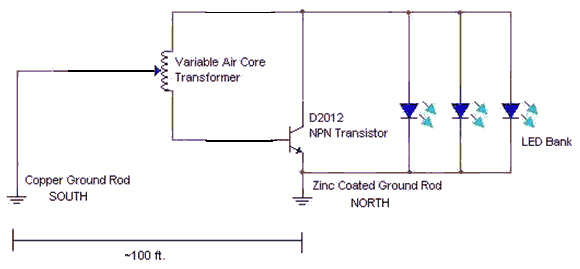 "Earth Radiant Energy Receiver"
by "Tesla Cult"
Something I had recently realized about my own attempt,
quite a while back now, was that I had used around 100 KHz switching,
but I had used an iron powder coil core. Iron cores are only good up to
a few hundred hertz. I should have either reduced the frequency by 99+%
or used a ferrite or air core coil. In Tesla Cult's circuit,
the
frequency is set by the capacitance of the antenna in conjunction with
the inductance of the coil, forming some sort of
oscillator circuit.
The next morning it occurred to me to click on "Tesla
Cult" channel specifically. He has done a lot since 2012, with some
bizarre looking stuff. The next step from the above was to move the
"south ground rod" connection instead to an antenna, for which he used
his anodized window
frame. It was then lighting about 35 of the same LED.s. He said the
frequency was about 100 KHz, but there were oscillations at 500 KHz so
that would be a better frequency. He said he'd need a new coil to get
that.
I thought I should continue viewing his videos, but on looking them
over, it seems that after the apparent success of apparently generating
at least a few watts this way 'from thin air' he diverted into other
things.
But he was getting energy even without a couple of "the
usual" key pieces, which might amplify it greatly. Perhaps I'd switch
to his air core coil, keep my own 555 oscillator and MOSFET driver
circuit, and resume my own experiments in this field. Many things could
be tried just for an antenna, as well as for tuning components and
circuits. The coil/transformer can be made by hand, and its pickup
point is tunable. A tuning capacitor might be had from an old radio
dial. The "subharmonic resonance" with the lambda rays is probably a
key. Tuning appeared to be finnicky and also a key to operation of
Moray's device.
Suddenly, after all this time, I had the thought of why my
transistor had got hot and burned out in my earlier attempt. On the
27th I looked up the schematic and sure enough -- no flyback diode to
shunt a high voltage spike as the coil turned off. It was the same as
when the flyback diodes had been left unconnected in the new motor
controller, causing those ones to get hot and burn out. And the reason
for that was... it wasn't in the original schematic I copied the driver
from. Perhaps their inductors were so small they weren't needed? I
added one in. The antenna and ground seemed to be a key both in "tesla
Cult" and Moray's receivers, so I added an antenna connection terminal
separate from the coil. Looking at a circuit of Moray's someone had
drawn from memory, I also added a diode on the antenna line. There's
always been some elusive DC component to all of this, and the air
becomes more and more positively charged with altitude (lightning is
when this potential suddenly discharges, ionizing the air).
Another Energy Source: Atmospheric Charge?
Then on the evening of the 27th it hit me: Tesla's
experiments were originally intended to capture electricity from the
static charge in the air. Franklin's kite experiments were also aimed
at learning more about this. Evidently on a good day, the positive
charge of air (shortage of electrons) increases (to our considerable
surprise when we first learn of it) by up to around 100 volts per meter
of altitude. And a lot can happen with this charge prior to - or
without - a lightning strike. More conductive channels such as
"lightning leaders" and "return (ground) stroke channels" develop in
advance of an actual lightning strike. Can they develop and large
charges of electricity be tapped without actually causing lightning?
And Tesla certainly made a lot of actual lightning, too! In fact, a
read at Wikipedia reveals that there are still a lot of unanswered
questions about atmospheric charges and lightning. Is lightning
triggered by cosmic rays? (or maybe lambda rays?) Why does it generate
X-rays and gamma rays when the voltage is supposedly too small to do
so? And yet the overall potential vertically through the atmosphere can
be a billion volts - Wikipedia's figure is the same one Moray mentions
in his description of his "radiant energy". However, at 60 miles, below
the ionosphere, it is around 360000 volts.
It is only natural to wonder about harvesting this known
source of electrical energy. A small device can easily be made with an
antenna, a ground, and a few diodes and capacitors, which will
gradually build up voltage to several volts from airborne electric
charge (or from nearby power lines or radio), and very gradually charge
a small battery. This is similar to Tesla's two 1901 patents on the
subject. (I made one in September 2013 from a "Tesla" circuit found in
various places on the web, shown in TE News #68.) But calculations and
experiments reveal that such passive, untuned devices would need
gigantic antennas to capture much energy. (However, people have been
electrocuted by the charge picked up by unconnected power lines, and a
long steel cable hung from a helicopter is said to make a huge spark
when the bottom touches the ground.) But if the antenna is very tall
(eg, Franklin's kite), the voltage is so high it's hard to utilize it.
Tesla, who doubtless used a very high up antenna, noted that the
charges would build up until they broke through the dielectric material
of most capacitors.
The stuff I'd now been studying for many days started
clicking into place, that it all pertained to capturing atmospheric
electric charge and not radiant (or "mysterious") energy per se as
everyone seems to suppose:
* It has to be well grounded - the earth has the negative charge.
* Large, perhaps insulated antennas to get the positive air charge.
(why would a big antenna be needed to capture picometer(?) wavelength
rays?)
* Hi dielectric constant antenna insulators for high capacitance (the
opposite of what cable insulation makers try to achieve).
* A diode in the antenna line.
* Tuned circuits, usually at ultrasonic or radio frequencies (LF or MF).
* Spark gaps or spark plugs that suddenly discharge or transmit high
voltages obtained.
* More energy during the day than at night and early morning --
following the times of day atmospheric charge is greater and lesser,
and vaguely aligned somehow with the sun. (It would seem the sun's
radiant energy is the major source of the atmospheric charge, so in a
sense it's an indirect harvesting of radiant energy. But it still works
at night.)
* "Tesla Cult's" antenna noise spikes seen on the oscilloscope from
distant thunderstorms. Just how far did lightning energy travel through
the atmosphere, and how much energy of a dynamic nature was still there
in the absence of actual lightning and storms?
Some of these techniques starting with Moray's seemed to
be inducing high voltage transient fields into the atmosphere around
the antenna, like a radio transmitter. This tuned electromagnetic
excitation of the air might well cause far more interaction between the
antenna and the atmosphere than just a passive antenna and circuit. As
the antenna voltage swings negative during its oscillations, it should
act on the charge in the air as if the antenna was at a much higher
altitude, pulling positive ions to the high dielectric insulated
antenna as a capacitance effect. As it swings positive, they should be
repelled away again. So it's 'stirring' the atmospheric ions instead of
just waiting for them to wander by. And perhaps some of the atmospheric
ion channeling effects which are precursors to lightning ("lightning
leaders", "return stroke channels" - see Wikipedia, "Lightning") may be
generated near the antenna. This could greatly increase the volume of
air interacting. The frequency of resonance with the air may depend on
the antenna, especially its length, or it may be a property of the air
itself. (Obviously I don't have this all figured out, but surely there
must be some dynamic atmospheric effects occurring.) Charge from the
air would be transferred with each cycle to the circuit, which can flow
to ground through an electrical load, powering that load.
Cyclically discharging an elevated antenna to ground - or
lower - would bring the antenna repeatedly down to the voltage from
which it would start to recharge fastest, providing the most current.
If the voltage was then taken up high, perhaps even above the ambient
charge at the antenna altitude, it might in some way "reset" the air
around the antenna and prod it into faster charge transfer.
Ultra high energy, 'ludicrous frequency' (eg 10 trillion
EV, 10^27 Hz) lambda rays even beyond where Moray described
are now known to exist, and are probably the source of energy for some
"radiant energy receiver" devices with no discernible antennas. But
grounded devices with antennas placed well up off the ground such as
Moray's and "Tesla Cult's", are more likely getting their energy from
the atmospheric charge, but collecting it far more effectively with
their oscillating circuits than with "Aerial Battery" passive DC
circuits. Electricity is literally being pulled out of thin air. or at
least regular air.
(When Tesla lit banks of light bulbs in a field with such
devices, it would seem he was transmitting a concentrated ion stream
from special ion transmitting tubes located elsewhere - the source of
the energy, of most of the charged ions, was the wireless transmitter
of radiant electricity, of which he spoke. This appears have been much
confused with "free energy" from ions naturally in the air. And his
primitive, passive 1901 DC ion capturing patents seem to get confused
with his separate 'bifilar coils' patent and with later ideas and
writings such as Moray's powerful (1925-1929) energy capture device.
Tesla spoke to a newspaper in 1933 about unlimited free energy that was
surely soon coming to mankind, an expectation perhaps based as much on
Moray's work as his own.
Tesla's own last patent seems to have been in 1928,
unrelated to energy capture. He did do some later work on a particle
beam weapon, the original "death ray", and on what may have been the
original idea for HAARP. He hid some of his later designs realizing
their potential for great harm as well as for good. The US government
seized all his designs on his death in 1943 and later wouldn't admit to
having them. Reagan's "star wars" program as well as HAARP may have
been mainly based on these designs. But I digress.)
The air has the energy! Lightning is the spectacular
discharge of the air's energy. When there's no lightning, which has far
more energy than can be handled anyway, some lesser amount of energy
must still be there. It appears Moray and others figured out how to tap
it. If I'm right Moray was off base thinking he was capturing ultra
ultra short wave radiant energy -- his antenna height and size indicate
he was surely tapping atmospheric charge energy.
So my working hypothesis for a potential 'atmospheric
energy harvester' experimental project is that the energy comes from
the known atmospheric charge, amplified and made accessible by means of
a tuned oscillator circuit, with of course the antenna, ground, and
other suitable circuit features. (The antenna is ideally about 65 feet
up and at least 80 feet long according to Moray - but an elevated
insulated plate might work fine too.)
IF I can make it work, it could supplant most
other energy generating projects. Self-turning magnet machines, solar
PV, solar hot water, wind turbines, and even ocean wave power and
floating river hydro would probably lose much of their attraction. The
main drawback would seem to be that an installation with a big antenna
and a ground wouldn't really be portable (ie, for electric cars. But it
might work with ships and large vehicles like trains?) And I suspect
that units located too near each other would probably lose power - that
the power available in an area is in fact finite, and they would
compete to harvest all that's available in the vicinity.
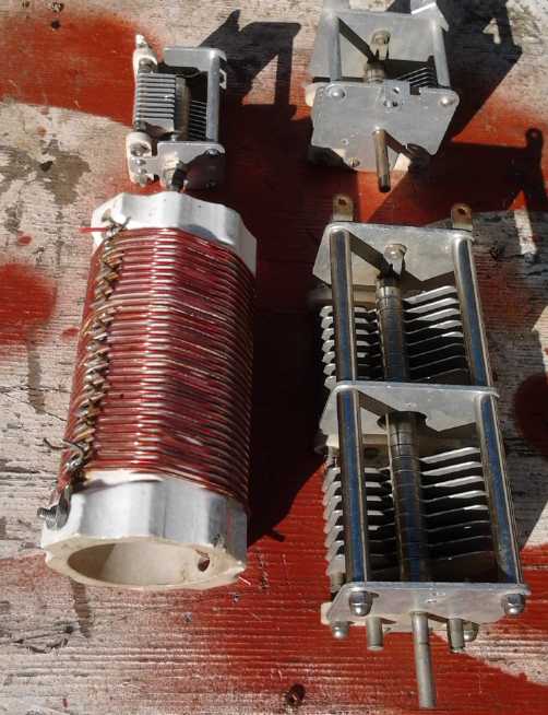 On the 28th I drew
up a schematic. On the 29th (after getting the switched reluctance
motor running!), I went to Microsec R & D and (by invitation) got a
big air core coil and three tuning capacitors from their "museum"
section. The coil looked like about what I had intended to make, and it
had a solderable point for a tap on every second turn, of which there
were 32, with an inductance of about 25µH. It was wound on a
glazed ceramic insulator - a good improvement over a plastic pipe that
could potentially melt. The possible uses for the tuning capacitors
were rather speculative, since I didn't draw a capacitor in the
circuit. I figured the antenna was the capacitor. But I might need to
do some tuning that a tuning capacitor could help with. The largest one
(physically) went from about 2 to 95 nanoF. The plates were over 1/16"
apart, so it should take quite a high voltage. The next day I returned
the other two and picked up books on design of LC oscillators and radio
transmitters. (and an evacuated tube heatsink for peltier module
experiments, that happened to be sitting there.)
On the 28th I drew
up a schematic. On the 29th (after getting the switched reluctance
motor running!), I went to Microsec R & D and (by invitation) got a
big air core coil and three tuning capacitors from their "museum"
section. The coil looked like about what I had intended to make, and it
had a solderable point for a tap on every second turn, of which there
were 32, with an inductance of about 25µH. It was wound on a
glazed ceramic insulator - a good improvement over a plastic pipe that
could potentially melt. The possible uses for the tuning capacitors
were rather speculative, since I didn't draw a capacitor in the
circuit. I figured the antenna was the capacitor. But I might need to
do some tuning that a tuning capacitor could help with. The largest one
(physically) went from about 2 to 95 nanoF. The plates were over 1/16"
apart, so it should take quite a high voltage. The next day I returned
the other two and picked up books on design of LC oscillators and radio
transmitters. (and an evacuated tube heatsink for peltier module
experiments, that happened to be sitting there.)
On October 2nd I found a site that seemed to give some real background
on the energy issue and things happening from the 1880s to the 1930s.
It seems to be a chapter on Moray from a book called Lost Science
by Gerry Vassilatos from 1999.
http://customers.hbci.com/~wenonah/history/moray.htm
It appears that patents for "static-field" "aerial
batteries" "fill the archives", and that some of them were used to
power machinery. In a most interesting paragraph is:
"While investigating the output of his
device, he [Moray] discovered a feature of the natural static energy,
which had somehow been overlooked by other aerial battery designers.
The electrostatic power had a flimmering, pulsating quality to it. He
learned of this "static pulsation" while listening through headphones,
which were connected to telephone wires. The static came in a single,
potent surge. This first "wave" subsided, with numerous "back surges"
following. Soon thereafter, the process repeated itself. The static
surges came "like ocean waves". Indeed, with the volume of "white
noise" which they produced, they sounded like ocean waves! "
Herein we recognize the AC or dynamic component of the air
charge, and perhaps why an oscillator might harvest much more energy
than a "static-field" receiver, and with a much smaller antenna. And we
understand that Moray was indeed the first to discover it. Farther down
we discover that the ground side of the circuit also has some
unexpected characteristics and energies. Specific points in dry ground
have energy characteristics not shared by other nearby points or by wet
ground.
In fact, the article contains a wealth of natural energy
related information, some of which has been very nearly forgotten -
such as some early telegraph stations that worked fine with utterly
dead batteries via the ground energy. I read through it that day,
neglecting getting this newsletter out. And now I'm not sure. Moray may
have been harvesting lambda rays rather than atmospheric charge. I'll
have to go through it carefully again before I start trying anything!
Electricity Storage
-
Turquoise Battery Project Etc.
Honda Insight NiMH Battery
Charging the rewired 14.4 volt, 65 AH "Orange Bamboo" NiMH high rate
battery
On about the 15th somebody gave me a Honda Insight hybrid
battery. It consisted of 120 nickel-metal hydride "D" cells. 10 sets of
12 cells were spot welded together, six cells going to the 'back' and
the other six returning to the 'front', where the external connections
were made. They were all nicely spaced by molded plastic spacers, with
air space between each of the twenty runs of six, ensuring good cooling
and that nothing would short circuit if things got hot and melted the
plastic cell sleeves, which were single sleeves of 'heat shrink' over
all six cells. There were three temperature sensors, buried under
three of the sleeves, and some other "PTC" temperature sensors that ran
right along the sides of each and every "stick". It was electrically
divided into two 60 cell, 72
volt batteries, which probably got merged into 144 volts when
connected. A cover of metal pieces and extruded styrene(?) foam covered
the battery. Surprisingly it weighed 55 pounds, about as heavy as a
lead-acid battery of similar nominal rating. It might outperform it by
30% or so and it would surely
(at least when new) long outlive it.
With the battery were the Insight hybrid control parts -
the motor controller and charging system. I didn't know what to do with
these except to salvage some very nice heatsinks. I wasn't willing to
put in the time to learn the details. (If the motor had been included
it might have been a different story. Even so, I have my own motors.)
Nothing seemed to be known about the car the parts came
from. It would have been impractical to try breaking up the welded sets
of twelve, which were all fully discharged - some were down to 9 volts,
and they'd have been there for an unknown length of time. That's below
the "one volt per cell" minimum where corrosion starts occurring, but I
decided to treat them all as "good" for the purpose of turning it into
a single 14.4 volt battery. It would need a special charger for that
voltage... but if used in the RX7, it would be up to 142.4 nominal
volts, almost the
intended voltage of 144. If the cells were 10 amp-hours that would make
another 100 amp-hour battery for the RX7-EV, but I expected they were
probably about 7 or 8 amp-hour, very high rate cells, capable of
zillions of charges and discharges including sudden very fast charging
from regenerative braking and steep discharges during acceleration. A
check on line indicated they were probably only 6.5AH. A company said
they had superior replacements - higher rate and 8.0AH (...and 2100$US)
owing to improvements in manufacturing since the Insights (2003-2006?)
were made. Being very high rate would help them last longer in the RX7
than the same 65 amp-hour rating in a regular rate NiMH (or lead-acid)
battery, but that capacity seems substantially lower. (On line there
are various instructions for rebuilding the Insight battery with
regular NiMH "D" cells. I wonder how that works out?)
On the 17th I used up the short copper connection bars it
had, and then made my own #14 AWG short connection wires for the rest,
to wire all the tube sets in parallel for a 14.4 volt battery. With all
the air spaces it was physically large and might be hard to fit, but
surely it could go in somewhere?
Later I ordered 6 more sticks of 12 batteries for 24$US each (or "12
sticks of 6" for 12$) off e-bay. ("4 sold in the last hour"... I looked
again and it said: "5 sold in the past hour"... and I took the rest.)
It seemed I happened to look at exactly the right time and that the
seller sold them all in an hour. Then on October 2nd I discovered in my
e-mail that before I saw that deal, I had bid on an e-bay auction for a
set of 5 more tubes and won - for 99¢US! Now I'll have 2 whole
Honda Insights worth and a tube to spare.
I only vaguely remember seeing the auction, and thinking
ya, that'll be way over 100$ before bidding ends, and probably I bid
about that amount just in case it wasn't. But no one else bid!
I had to have both sets sent to my phone number "c/o
Clipper Cargo" in Seattle WA because the sellers wouldn't ship to
Canada. The Victoria Clipper jet catamaran then brings them across the
strait to Victoria on its regular passenger route for 27$US and I have
to clear them through customs myself. (What do people farther from the
border do?)
So shipping will make it total about 170$C. Plus any taxes
customs decides to charge me... on 99¢. (That's 99¢, +99+27
$US shipping and the humungus rise of the US$ versus all other
currencies as nervous investors seek the "safest" asset. But all fiat
currencies are inflating away.)
Later I got 12 lithium iron phosphate cells (36v, 40AH)
for 600$ in town, which was another great deal. I could now power the
Chevy Sprint at 36 volts without buying any golf cart batteries, just
lots of NiMH D cells and 12v 320AH of paralleled lithiums - if I ever
get it running.
http://www.TurquoiseEnergy.com
Victoria BC Canada