Turquoise
Energy Ltd. News #93
covering October 2015 (posted November 8th)
Victoria BC
by Craig Carmichael
www.TurquoiseEnergy.com
= www.ElectricCaik.com
= www.ElectricHubcap.com
= www.ElectricWeel.com
Month In Brief
(Project Summaries)
- Pulse Width Modulation for motor controllers - Atmospheric Energy -
High vacuum pump for evacuated tube radiators for thermoelectric
cooling? - NiMH Battery connection problems.
In Passing
(Miscellaneous topics, editorial comments & opinionated rants)
- Legislation must be Ratified by the People - Energy Density:
Gasoline vs
batteries? - Importance of Location for Industrial Activities -
Negative interest rates - Another High Frequency Trading Scam - Itchy
chocolate - Book Barn Mini Library - Supercorder at Band & more
interest in it
- In Depth Project Reports -
Electric Transport - Electric Hubcap Motor Systems
* Unipolar Motor Controller: pulse speed control input to improve
performance.
Other "Green"
Electric Equipment Projects
* Peltier Module/Thermoelectric Cooler ('TEC') Experiments:
supply
voltage versus attained cooling - 15 amp Peltier module - better ice
tray - internal fan - evacuated tube heat radiator - DC to DC converter
Electricity Generation
* Atmospheric Ions - free energy from the electrical charge of thin air?
* Sigh, month ends with far more questions than answers.
Electricity Storage - Turquoise Battery
Project (NiMn, NiNi), etc.
* Lead? Lead? The acid battery element has potential uses for alkaline
or salt batteries, where it just might have 'forever' cycle life.
* Lead-acid battery charging & cycle life extension: pulse charging.
No Project Reports on: Variable
Torque Converter Transmission, CNC
gardening/farming machine, Electric Weel, battery making, aquaponics,
Magnet motor project.
October in Brief
A lot of October just seemed to slide by without getting a
whole lot, or even anything, done on sustainable energy projects. There
were many things needing doing around the house. I went to Comox on the
last
weekend
for my mother's 90th birthday party, and then my brother who had come
from Toronto stayed
with me for a couple of days, leaving on Halloween morning. I caught
his cold, with
headache most days. That
delayed this newsletter as well as projects. Somehow, however, I have
touched on quite a number of diverse topics in "In Passing".
Early in the month I designed a circuit and PC board for a
pulse width modulator (PWM) for the motor controller. It would be an
external input to
the motor controller board, the PWM at 7Hz replacing the usual analog
speed control
potentiometer.
According to things I've heard, at least with a unipolar
motor controller, one gets better
energy usage with low rate pulses to get the desired power level than
with analog modulation, with the reason evidently being to saturate the
magnetic cores of the coils (or at least to run always at full power),
then letting the force drop to zero, repeating
in succession. This may not entirely make sense in a traditional design
sense, but according to many it works. But after completing my design
and layout there was a
long pause.
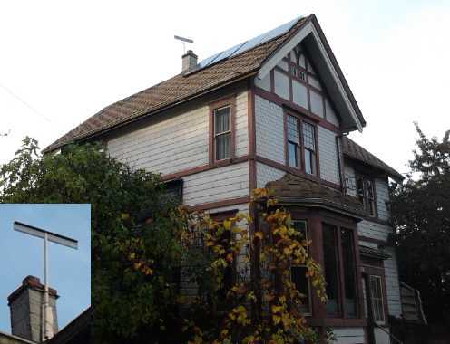 I wanted at
least to start in on atmospheric energy
experiments. I made an antenna for it and installed it at the peak of
the roof by the 16th. I ran a
shielded cable down the same route as the solar panel cables into the
solar equipment closet.
I wanted at
least to start in on atmospheric energy
experiments. I made an antenna for it and installed it at the peak of
the roof by the 16th. I ran a
shielded cable down the same route as the solar panel cables into the
solar equipment closet.
In all the searching through youtube for atmospheric
energy
info, inevitably some enticing videos about other forms of 'free
energy' including magnet motors were in the 'suggestions'. One person,
"(Something) Stators", had a bicycle wheel rotor test setup with a well
shielded
magnet on his stator, which he said offered the rotor magnets little
resistance as they approached but gave them a big push as they passed
by. It was similar to an idea of mine but he had done a working
construction with the bicycle wheel. I too think the shielding and
concentration of flux is
the
key - or at least one key. I started coming up with new designs in my
head again.
However, only once did he seem to have a design that
actually kept
turning. Even then, after a bit his cat, tentatively pawing at it a few
times,
dragged it to a stop, showing (along with the pretty low running speed)
how little actual torque there was. As a generator it
wouldn't put much out. Yildiz, with his 2000 magnet motor, seemed to
get a measured maximum of 200 watts AFAIK (tho I remember hearing 400
somewhere). Given the time quite a few people have put into getting
meager
results or failures, I think I'll stick with the atmospheric energy
as the better bet!
Moray got up to 50 kilowatts. Five kilowatts would of
course be fantastic.
(If I ever get my bitcoin miners running properly, I could then run
them and they'd also heat the house for free!) One KW would
still be great. A hundred watts would require installing a goodly
number of
antennae and units to make a real dent in the hydro bill. Ten watts
might be practical for limited off-grid applications. Of course, a unit
generating 24/7 would have
far more impact than solar panels of the same rating that run a few
hours a day and only
when it's sunny and there are no chemtrails. But reading more on Moray
at the start of November, I discovered that his later units actually
needed no antenna or ground, and worked for example inside a submarine.
That would indicate he was surely harvesting "lambda rays" rather than
atmospheric ions - at least with his later units... but weren't they
just derived from the earlier ones? Hmm, hmm!
Again I got sidetracked into other things. It was the end of the month
before I tried the oscillator(?) circuit of 'Tesla Cult's youtube
videos of 2012. It didn't seem to work for me. Furthermore, the
oscilloscope disclosed only a 60 cycle hum at about .4v peak to peak
and virtually no DC component. There was none of the high frequency
noise components noted by Moray and seen on Tesla Cult's oscilloscope.
Perhaps insulating the antenna with high dielectric constant material
as suggested by someone else is a mistake. Maybe good, clean metal is
better. Gold plating?
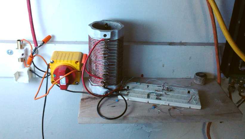 The bottom end of the atmospheric charge energy
experiments, in the solar equipment closet.
The bottom end of the atmospheric charge energy
experiments, in the solar equipment closet.
Cable from antenna with spark gap, antenna grounding switch, shelf with
the air core coil/transformer and circuit breadboard.
(At the far right is solar PV wires and equipment.)
Someone long involved with refrigeration came over (from
across town in an electric handicapped scooter) and we
talked on the subject. He mentioned having a high vacuum pump. I
thought it might be used to make the evacuated tube radiators I've been
wanting to make but have been unable to get a sufficient vacuum in by
the steaming method. He pointed out that the water in the pipe would
turn to steam and condense in his pump. Somehow I quickly
thought of freezing the water and pipe in the freezer and then
evacuating it. Then the water (ice) would stay in the pipe as desired.
He thought that could work.
Now I must talk with him again soon and get moving on it, as there's no
guarantee at his age and health he'll be around and mobile when it's
convenient for me to get
around to it. Maybe I can learn some more, and perhaps buy the pump?
In August and September I had been smelling a "burnt
plastic" smell at times when driving the Mazda RX7 EV - often when I
needed the most power, climbing hills. Finally in September the culprit
was located: a loose connection nut on the soldered nickel-metal
hydride battery in the back of the car. (this battery: see some TE News
issue of maybe 2013.) With the loose connection, the bolt with the wire
had been getting hot, and pressing against the side of the neighboring
lead-acid battery it was melting its way through the side. Luckily it
hadn't
got all the way through the wall yet, and just as luckily the car
hadn't let me down going up a hill. I tightened the nut and put a piece
of wood between the two batteries to keep them apart.
The smell stopped, but the problems weren't over with. I
connected the NiMH battery to one of the voltmeters on the dash and
found that it seemed to now be the weakest of all the NiMH batteries,
with the voltage dropping lower when power was needed and the charge
being depleted sooner than any of the others. Although it was the first
soldered NiMH battery I had installed, it had been with all new cells.
I wasn't driving more than about 4 miles, by which time it obviously
needed recharging.
Finally it occurred to me that it behaving was as if it was 50
amp-hours instead
of 100. And it was made in two 50 amp-hour boxes.
I pulled it out, brought it inside, and started to
disassemble it. On the bolt that
had the loose wire there was a nut with melted plastic on it facing a
washer with melted plastic on it, and the wire in between from the
lower box to the upper had some grit on it. Although the nuts had been
tightened, these things had conspired to cause the lower box to be
unconnected. I cleaned it up. While it was out I opened the lids, and
found that two of five wires in one box had come unsoldered and so two
sets of 10 amp-hours weren't making connection. At first I thought they
must have melted off, but close examination showed untinned copper
surface -
the original solder joint had been poor.
Also in October, the owner of the one NiMH D-cell car
battery I had made and sold (somewhat ironically for his Honda Insight
hybrid) brought it in because after 3-1/2 years it
wasn't working well. (battery covered in some TE News issue from 2012
or 2011.) I had
asked him a couple of years ago to bring it in as I had discovered the
safety concern with just the thin plastic sleeve casings on the cells,
and had had some packs burn up on me after being badly overcharged. And
I had used the stiff copper "buss bars" to connect the cells together,
which I gradually found out gradually come loose with vehicle road
vibrations. I wrapped the cells in masking tape for thermal protection,
and replaced the bars with AWG#16 flexible stranded wires, formed into
little arcs to allow for more flexing. There were 3 or 4 copper bar
connections that had come loose, definitely explaining the reduced
performance, and a couple more that might have gone soon. One of the
terminal posts was also quite loose, and I pointed out that the
clamping nut had to be on tight to ensure good connection. I tested all
30 cells with a voltmeter while I had them apart, and they were all
holding their voltage.
As I write about the loose bolt/post, a better system
comes to mind: instead of clamping the connection bar between the bolt
head and the case with a nut on the outside, clamp the internal
connections between the bolt head and a nut inside
the case. That (hopefully) can't be loosened from the outside. There
would still be a nut on the outside to hold the bolt in place, but it
wouldn't affect the connections and pehaps cause the case to get hot if
it came loose.
On the 26th I finally got back to the PWM for the motor
controller and
I got the board made, working (not without a couple of little problems
along the way), and installed in the test controller. Then it sat a
while again. On November 3rd I decided as it was made I'd better at
least try it out for this newsletter, so I hooked it all up and ran a
few tests. It seemed to run about the same except for the definite
pulsing action. As the power supply was balking at the currents, I
powered it off the handiest thing: the 14.4 volt, 65 amp-hour Honda
hybrid battery. So I was running it at half the voltage and the same
current, and getting similar results. That seemed agreeable. I bypassed
part of the shunt resistor (for a lower shunt resistance) and got
higher currents in both directions, which provided a higher but still
very low top RPM of about 225. The DC clamp-on ampmeter attached to the
oscilloscope seemed to indicate that the energy return current spikes
were higher voltage than the supply current spikes. Doubtless that must
mean they were a little narrower, but the battery voltage dropped
surprisingly little over the course of the testing, indicating pretty
low energy use. The peaks were about 14 amps used for the 225 RPM,
delivered as short spikes of 150 to 300 amps with return spikes of
around 250 to over 400 amps. The energy return coil still got hot, and
obviously the average supply current has to be a lot higher to get any
real power out of the motor.
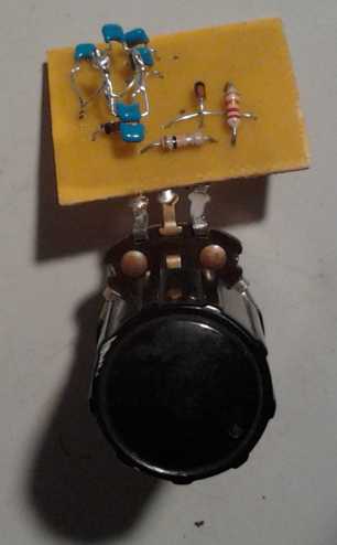
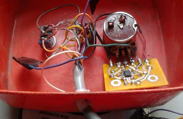 Pulse Width Modulator Board on pot, and
installed in hand-held control (SOIC 555 timer
chip on bottom)
Pulse Width Modulator Board on pot, and
installed in hand-held control (SOIC 555 timer
chip on bottom)
Aside from the direct-soldered potentiometer it has 3 leeds coming off
it, just like the analog pot alone:
Ground, Power (12V), and PWM out (0 or 4 volts with a resistive
divider).
(Circuit drawings/files in detailed project report.)
In Passing
(Miscellaneous topics, editorial comments & opinionated rants)
Legislation must be Ratified by the People
As we enter the internet age, new forms of communication
and democracy, such as direct voting via the web are becoming feasible
for the first time, and at the same time there is a global awakening in
social consciousness.
Today's governments have mostly turned their backs
on the real needs of their citizens and social progress in favor of
special interest groups who broker their power for profit. When the
politico-economic power base is shattered as it doubtless will soon be,
from semi-chaos we will have
the chance to reorganize from the local level up in sustainable ways.
On the one hand, there is a need for elected government
made up of experienced, concerned citizens who have spent more time
than most studying the problems of society and devising solutions. On
the other hand, centralized power seems to increasingly attract
virtually the opposite type of people: the corrupt, the greedy, the
power hungry, the manipulators - insincere liars and sociopaths, devoid
of progressive ideas and ideals of social
sustainability. And these shut the honest and good-seeking citizens out
of the
fierce competition for political and economic power. We need leaders,
not rulers.
Some aspects of power need to be widespread, so that those
elected will have no opportunity to run roughshod over the rest, and
holding office won't attract those types. This has become possible.
People today know a lot more than those of previous generations, and
can learn more about what's going on more quickly. They will want to
know first why their social and political institutions, unexpectedly to
most, suddenly fell apart, and how it was that so many were so asleep
until it happened.
And they will want a more direct say in running the new ones to ensure
that autocratic decisions aren't imposed on them by those from whom the
police and the military take their orders.
Of course the citizens need the right to hold referendums
on any chosen issue. But it now seems to me that a possible solution, a
balance to the centralized power, is that any bill passed by a
legislature would have to be ratified directly by the citizens,
doubtless after time for due consideration and discussion. This seems
like the best way to eliminate odious and
perhaps deceitful legislation turning peoples' rights over to the state
or to special interest groups, and increasingly micro-managing
everyones' affairs with thousands of laws and bylaws. Such bills would
probably fail at the public scrutiny level, and the leaders
would realize it would, therefore they're unlikely to be pressed
forward,
and the types of people who would press them will be the ones who won't
bother running for office. Both of these polling
functions would be implemented via the internet in some form.
Gasoline: high energy density?
I happened to look up aluminum ion batteries on Wikipedia
to refresh my memory, and saw it said that even tho they were over a
kilowatt-hour per kilogram, petroleum was much higher energy density.
So I looked that up, converted joules to kilowatt-hours, and got 12.33
KWH/Kg for gasoline. At a glance, this is twelve times better. But one
must consider that the automotive gasoline engine is seldom over 20%
efficient, and add to that the inefficiencies of the drivetrain
components like the 30%-40% loss in a typical transmission
(standard-automatic). Call it 50% loss overall. The overall efficiency
of the typical car drive is then around 10%. So the 12.33 effectively
becomes 1.23 KWH/Kg. The rest of the energy is wasted as heat. An
electric drive can be made much closer to 100% efficient (up to the
rubber
tires and their road friction being similar), and of course a major
goal
of my
projects has been to improve efficiency, eliminating the wasteful
transmission one way or another and achieving the highest drive motor
and controller efficiency.
Of course no one is actually using aluminum ion batteries
at this point, and typical automotive lithium batteries are probably
under 200 WH/Kg at best. (Don't quote me on that!) Lead-acids are 40
WH/Kg or less. Furthermore, as the gasoline is burned its weight
vanishes, while the batteries remain as dead weight until recharged.
Still, there are promising new battery chemistries out
there such aluminum ion and several enabled by new DES electrolytes,
and as battery energy density increases over 100 or 200 watt-hours per
kilogram, the weight of the batteries as a percentage of total vehicle
weight starts to shrink and battery weight starts to matter less than
battery cost and cycle life. Add to that a reduction in required
battery capacity through higher efficiency, the ongoing cost of
gasoline and the likelihood that it won't always be available, Fast
charging and new public charging stations popping up everywhere, and
the electric car starts becoming the obvious
economic as well as ecological choice.
Importance of Location for Industrial Activities
I read an article in the Financial Times [http://www.ft.com/]
about industrialization creating less and less in the way
of jobs and wealth with each new industrializing country. I found one
of the comments someone posted below the article to be of particular
relevance to the work I've been doing. The writer says that industry
even in "industrialized" nations is concentrated in a small number of
"clusters". He went on:
"In a former life I have worked as an
industrial consultant and by observing it became clear companies inside
the industrial cluster have a competitive advantage in that they have
access to a dense local network of specialized suppliers and know-how
that often requires proximity to work well and is absent outside the
cluster. In other words, network effects are at play. Furthermore, the
presence of a sophisticated manufacturing base allows new types of
technologies and niche suppliers to develop, often requiring proximity
to customers - e.g. machine vision systems for automated quality
control. These then further strengthen the competitive advantage of
that cluster. The more technology advances, the stronger these
network effects become thereby further cementing the competitive
advantage of the cluster versus the world around it. 15 years ago, when
visiting competing companies in the same sector, it was obvious the
ones in Germany/Italy were way ahead of those in France, Spain as the
latter lacked plug-in into a strong local eco-system. I suspect since
then the divergence has only widened.
"This is also why Australia's doesn't manage to industrialize and
despite its highly educated population, one should always be short the
Australian dollar outside a commodity boom. This is also why Greece
will always run a deficit when in a currency union with Germany and the
EZ crisis is perpetual: if Greece were somehow geographically moved in
between Germany and Switzerland, its problems would quickly
disappear.
"This is also why everybody now wants to move to Germany as the
manufacturing base won't come their way. They have a point.."
I have struggled from the beginning of the "car
hybridization" projects with the fact that nobody around here seemed to
know anything or have any parts when one gets into the nitty-gritty of
various mechanical and technical areas. If I was located in a
"cluster" area where cars were manufactured, I'm sure I'd have had a
much easier time with a lot of things.
But I think as the internet has further developed, some of
the handicaps are being removed, and that this trend will continue into
the
future. More information is more accessible, and it's getting easier to
access parts and services. Progress in manufacturing automation has
also progressed. With various computer controlled devices, for example
abrasive waterjet cutting of steel and 3D printing, many things that
used to require expensive design and setup or painstaking fabrication
with lathes, welders and milling machines, can now be designed on a
computer at home and done either there or at a local facility by
automatic machines. Low cost
services are available for making printed circuit boards in China
simply by e-mailing the design, with the finished boards being thrown
in the mail - no need for proximity there! - and there are now
automated PCB
assembly facilities even in Victoria BC. And prototype boards can be
done
in a day at home as I've been doing, with laser printer toner transfer
techniques.
As communication and distribution improve, more and more
we can have self-sustaining local communities.
Negative interest rates
Today bank deposits earn almost no interest. With
inflation, it's effectively negative interest rates - the buying power
of your savings shrinks. For many currency is safer at home in cash. (IF
it
can
be very well hidden, preferably divided into small packets, and
that doesn't mean somewhere in your bedroom. A hidden safe, well bolted
down, might be invaluable - they start at under 100$.) Or maybe
some in a non-bank account such as paypal. In some European countries
actual negative interest rates, albeit
small ones so far such as -.1 percent, have been applied to bank
accounts.
It's
hardly a way to watch your savings compound! In recent weeks there have
been mutterings from the US "Federal Reserve" banking corporation about
instituting "NIRP" (negative interest rate policy) in the USA. Such a
"policy" hardly seems designed to attract deposits. Indeed, it has been
noted that people in affected countries have been gradually withdrawing
their money. In order to combat this, rather than making banking more
attractive, there are plans, or at least ideas, afoot to ban cash in
order to force people to keep their money in the banks - to force them
to lend the banks their money regardless of negative rewards and risk -
and by
the way
allow the government to spy on and review each and every financial
transaction of every person - rather than keep it more safely (less
dangerously?) themselves in cash.
I tend to dismiss this problem
because I think the whole ponzy scheme global financial system will
crash before such a system could ever be implemented. One can never say
what surprise tricks might be used to "kick the can down the road" a
little longer, but personally I expect the can to grow a handle well
within a year. Then it will be a bucket, and the financial system will
suddenly "kick the bucket" on its next kick. NIRP or "bail-ins" (the
everywhere-threatened direct theft from deposits by government and
banks) might do it, or the bond bubble implosion, or derivatives
dominos, or running out of gold or silver, or there might be some
unexpected cause. Expect chaos to spread quickly when that happens and
last for years (2 or 3?) until the survivors figure out how to get
vital trade and food supplies moving again.
In the meantime, as long as negative interest rates are
fairly and
consistently applied to all, I am for them! In fact, I look forward
eagerly to getting interest payments from the banks based on my
mortgage and
credit card debts instead of having to pay out on them!
Another High Frequency Trading Scam
Last February the CAVirtex.com bitcoin exchange in Calgary
Alberta announced it was shutting down, citing "a security problem". It
was a complete surprise to all. It asked all account holders to
withdraw their
bitcoins and Canadian dollars amounts within the next month and close
their accounts, and trading ceased in March. I withdrew "everything",
but
as it wasn't possible to get everything exact, I had left over one
penny and something like .00012 bitcoins - trivia.
The next surprise was two or three weeks later, when
CAVirtex.com re-opened under new management. It didn't look like
anything had changed a whit. My account was still there with the small
change.
But I had already noticed in the weeks leading up to the
closing that suddenly most of the trades were being front-run by some
high-speed computing algorithm. This has become common on Wall Street
in the stock markets (and as usual there's no investigation, and no one
is ever charged or goes to
jail), but is a huge cash cow in the bitcoin market on
CAVirtex.
The price of bitcoin having risen recently, I decided to
sell some to pay expenses. Normally, when you go to buy bitcoin on an
exchange you
can look at the
trading page and either offer the amount of the lowest sell offer and
buy immediately, or you can make a lower offer and wait for someone who
will sell at your price.
Now (buying) if the lowest offer to sell bitcoin was for
500 $/BTC,
you can offer that price to buy immediately. But when you do, your
purchase instead goes through for 499.99 $/BTC. Afterward, the bitcoins
for sale at 500$ are still all there: the seller has sold nothing.
Instead, when you hit the last key or mouse click to buy, somehow
before your offer hits the exchange, it's intercepted, and instantly
someone else
puts in a sales offer for your exact amount of bitcoins at 499.99$.
That
499.99$ offer takes precedence over the 500$ and immediately goes
through, so fast that it never appears on anyones' computer
displays in the 'bitcoins offered', only in the 'completed
transactions'
section. Unless he looks down there, the only thing the offerer for
500$ sees is that none of his bitcoin has sold yet.
The same thing happens with selling bitcoin: if the
highest offer to buy is 470 $/BTC and you offer to sell for that much,
your
trade goes through instead for 470.01$, and the would-be buyer is left
high and dry. Instead, the front-runner, who just sold bitcoin at
499.99$ moments ago, now buys it back for 470.01$ and pockets the
29.98$ (less the exchange's transaction fee of .75 or .5%). If the
exchange trades 200 BTC a day and the spread is 30$, and
if 90% of the trades are front-run, the scammers are making 5400 $/day.
This money comes off the backs of everyone trying to buy and sell
bitcoins on the CAVirtex exchange, who can't make their trades go
through except by buying and selling at the asked and offered prices,
always getting the least "bang for the buck" with most of the trades
going through the hands of the scammers who pocket the difference.
This is just now appearing also on the Quadriga.com
bitcoin exchange in Vancouver: I just lost a sale for .75 BTC, with a
"sell" offer
for 1.00 bitcoins being posted as I watched and asking a dollar lower
than me, which proved to be exactly the amount of an offer to buy 1.00
bitcoins just before it appeared. It was visible on the listing for
just a few seconds before the trade went through. Then I looked at
'recent trades' and saw that they all had been for a dollar less than
my price. I don't remember that happening before.
It may be that
the scammers have acquired physical intercepts into the exchanges'
internet
lines, so that all the communication goes through their
equipment
first and their computers can pick and choose with every transaction.
This would be a variant of what's been done to the New York stock
exchanges for high frequency trading. It may even be that it was the
scammers who re-opened the CAVirtex exchange
after it was shut down. They could certainly afford to buy it with
their illicit profits, and they certainly have every incentive to keep
their
rigged game running! And then they even keep the transaction fees.
Perhaps more needs to be done through "local bitcoins" -
private buying and selling of bitcoins not through on-line exchanges.
Itchy Chocolate
I used to get unbearably itchy in my 20s, and I scratched
so much I now have various nasty moles and things on my back and chest.
When I was 29 I finally discovered it was from eating chocolate, which
I was eating a lot of. I quit eating chocolate and gained much relief.
A lot
of things give me migraines, including most processed or non-fresh milk
products including milk chocolate. But after over 30 years, I forgot
the other reason I don't eat chocolate, and I bought a big dark
chocolate bar
at a grocery - maybe dark chocolate wouldn't didn't give headaches like
milk chocolate? After having too much for 2 or 3 days, I was unbearably
itchy the next night. I thought maybe pollen, which I'm allergic to,
had somehow got on my bedsheets. As I washed them the next morning I
remembered about itching from chocolate. I related this to a friend and
gave him the rest of the chocolate bar. The next day he said he had had
several itchy sessions at night for no apparent reason. I thought it
was just my own allergy. Is this a common reaction? After a few days of
itchy chest, I also got a zit there, also doubtless from the chocolate
(not from the itching per se).
Book Barn Mini Library

In the middle of the month I finally finished a project
inspired by a "resilient streets" meeting in the spring and made from a
boulevard giveaway cabinet I put a cor.o.plast "roof" on: a very local
place for people to exchange books. A number of books have come and
gone. I think more 'duds' have come or remain, and more interesting
ones have gone. The books mostly seem to have come in three batches:
the ones I initially set out, a batch someone else brought, and a batch
of cookbooks from another person. At one point, some 'librarian' set
them all up nicely. Someone kicked in one door. I feared it might soon
be completely vandalized and wondered if it was silly even attempting
it, but it hasn't happened yet. Lately there's been a big plastic bag
over it to keep the heavy rain out.
I found a video of the original "Resilient Streets" book
boxes, and they were nicer, mounting on posts and with glass (lexan?)
doors that open, to keep the rain out.
Supercorder at Band & more interest in it
Having been asked to leave the "Intermediate" band because
my Supercorder "doesn't sound the same as a flute", in the last week of
October I re-joined the "Junior" band, where the conductor, and a few
players who said something had seemed to be missing without my sound,
seemed more than happy to have me back. As there were no oboes I'll
mostly
play oboe parts - and sometimes flute where the oboe part has nothing,
tho there are six flutes this year.
There was further interest in my instruments in an e-mail. Some
else wanting to experiment with improving recorders asked where I had
got my information. That was here and there, and I realized that if I
wrote up some "tips and principles" of recorder and supercorder design,
it might save people a lot of time and grief. Doing so further
contributed to delay in writing this newsletter. And I think expanding
on the subject, showing some of my jigs and techniques, might also be
more than helpful to potential makers, so I may take some more time out
to do so. There are lots of guitar and violin makers and doubtless lots
of books and plans for them, but there's
really not much info for an aspiring woodwind maker to go on.
Newsletters Index/Highlights: http://www.TurquoiseEnergy.com/news/index.html
Construction Manuals and information:
- Electric Hubcap Family Motors - Turquoise Motor Controllers
- Preliminary Ni-Mn, Ni-Ni Battery Making book
Products Catalog
(Will accept BITCOIN digital currency)
...all at: http://www.TurquoiseEnergy.com/
(orders: e-mail craig@saers.com)
Daily
Log
(time accounting, mainly for CRA - SR & ED assessment purposes)
Oct 1-4: More research on aerial energy
devices - Read Tesla's famous patent on the subject. (Also watched a
technical video about Bedini motor.) But mostly editing newsletter.
5: Picked up NiMH Honda Insight battery sticks & cleared through
customs.
6: Researching on aerial energy (a couple of good technical videos -
Ion Power Group, more).
7: Started laying out a PCB for a 555 timer based PWM control to
attempt some additional pulse strategies with the unipolar motor
controller.
8: Finished PCB layout
9: More video 'atmospheric
energy' studies.> (Inevitably some stuff on magnet motors too.)
10: Still more video 'atmospheric energy' studies.
11: -
12: ditto to 9th and 10th. I also spent quite a while writing an e-mail
to MicroMetals[.com] looking for advice on coil core types for the
motor controller.
13:
Bought heavy "battery" switch for grounding atmospheric energy receiver
antenna. (safety for electronic circuits and for people, esp. me.)
14: Bought a "gutter guard" aluminum plate to use for plate antenna.
15: Constructed atmospheric energy receiver antenna assembly and
mounted it up on peak of roof. (~40' elevation above ground)
16: Ran cable from antenna to solar panel/12 VDC equipment closet.
17: Major cleanup of the closet.
18: Formed a ceramic insulator set for the spark gap pieces.
19: Fired insulator set in kiln, mounted it in wiring closet.
20: Finished up wiring spark gap and grounding switch, added a small
shelf to place circuit breadboard on for trying things out.
21: Wired up coil, connected it to antenna, and tried a couple of
things. (No notable results)
24-25: family
26: Made PCB of PWM control
27: Drilled holes in PCB
28: Mounted components & tested & troubleshooted(?) PWM
control, mounted in controls box.
29-30: family
Nov 1: Atmospheric energy experiments.
2: (bad cold)
3: Testing motor with PWM controller.
4: cold
5: cold
6: cold
7: newsletter
Electric Hubcap Motor Systems - Electric Transport
Unipolar Motor
Controller
I decided to try pulsing the drive at a low frequency,
just a few pulses per second, like maybe 6 to 8. This idea goes back to
my earliest motor controllers... like the one that actually moved the
car, however feebly, with direct drive on the wheel in October 2008.
This feat was never repeated in spite of improving the motors. A
couple of times I had heard Toyota hybrids make the same sort of
pulsing sound
as they started moving on electric power.
By
repeatedly giving the transistors a brief rest the current, and hence
torque, can be permitted to go higher when they're on without
overheating them. I also suspect it's the way to get the best
performance out of an "active generator", where the motor controller
acts like a "regenerative braking" circuit and dumps power 'back' into
the 'supply'.
For the PWM generator I made a simple 555 timer based
pulse width modulation circuit to feed 7.8Hz PWM to the controller in
place of the simple analog potentiometer. That's the Schumann resonance
frequency, for want of any particular reason for any particular
frequency. (Any RF emitted would travel around the world in all
directions and back to the motor in that length of time, FWIW.)
I remembered doing such a PWM generator when I had first
started in on doing motor controllers, and I looked for it in my EAGLE
PCB files. I couldn't find it. But I knew I had it somewhere! Where was
the circuit and the board design? At length I remembered I had wired up
the first controller on a breadboard, so there was no PCB layout. I
found the circuit diagram (originally off the web somewhere) in the
last undamaged copy of the "early motor controllers" manual - an image
of the circuit drawn on paper with pencil and pencil crayons. I had
forgotten how primitively I started out on all this!
I did the schematic in EAGLE and the PCB layout on the 7th
and 8th. There was one aggravation: I had selected the DIP package of
the 555 timer and designed the board. Then I checked my stock and found
I had the SO08 surface mount package instead. To change it on the
single sided board meant it would mount on the bottom and so all the
pins were not just smaller but mirror imaged. So it all had to be
rerouted, taking 2 more hours, and it ended up needing a jumper, which
it hadn't originally. But at least I shrank the board to 1" x 1.2". I
would just solder it onto the back of a rotary potentiometer control to
'mount' it. External connections are +12 volts, Ground, and PwmOut
(7.8Hz, 5 volts).
I finally got around to printing the 555 timer based pulse
width modulator circuit board on the 22nd. Here are the files.
EAGLE PCB CAD
files:
555-PWM.sch - 555-PWM.brd
Ready to print artwork (2 copies) at 600 DPI, with the pads expanded in
a 'paint'
program (Graphic Converter) to make solid solder points
on a single sided PCB:
555-PWM-x2.png
Schematic:
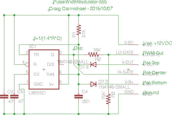
R1 should be omitted entirely. C2 and C5 are just filters
- .1µF or whatever is fine for both. R3/(R2+R3) sets the output
voltage. The potentiometer and C4 set the frequency. As it says in the
schematic, f = 1/(1.4 * R * C). If my 500,000 ohm potentiometer is 1/2
way, that's 250,000 ohms in each direction. That's muddied a bit by the
diode drops, but we'll use it. Let's see...
7.8 Hz = 1/(1.4 * 250000 Ω * C4 [in Farads])
1.4 * 250000 * C = 1/7.8 Hz or
C = 1/(7.8 * 1.4 * 250000) or
C = 1/2730000 or
C = .3663 µF.
.4 µF gives 7.1 Hz. So how about four .1 µF capacitors in
parallel? (Perhaps I should have allowed for multiple capacitors on the
circuit board layout?) We still have the diode drops to consider,
and the frequency might skew as the pulse width is changed.
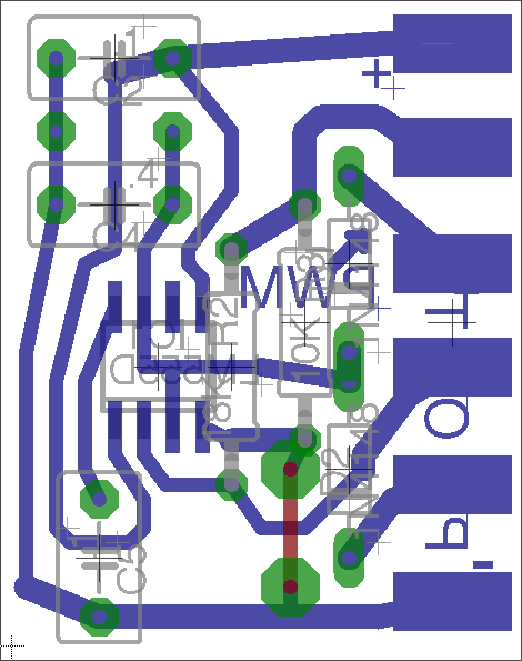 Image of (untested) V2 board
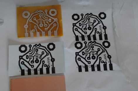 Artwork, first printed on paper (right),
then on toner transfer paper taped to the original piece of paper and
run through the printer again (mid),
then laminated onto a copper faced circuit board (lower) with 10+
passes through the laminator,
then the board is etched to leave the desired patterns (top).
I only got around to the project again on the 26th, when I
printed and etched the PCB. The next day's puny accomplishment was to
drill the holes. On the 28th I finally soldered on the parts and tried
it out.
Testing disclosed a mistake in the design, a hangover from
copying the schematic from something a little different. "R1" (51K
ohms) should simply be omitted. After a couple of hours debugging and
changing the design and layout, measurements confirmed that the pulse
width varied the frequency somewhat, from 125mSec to 170mSec, frequency
range 5.9Hz to 8Hz. Target was 6 to 8 Hz, so that's great. Pulse width
can vary from under 1% to over 99% by
adjusting the potentiometer. The potentiometer with the PWM board
simply replaces the regular control pot and outputs a duty cycle at
about 7Hz at 100% amplitude (or adjusted lower via R2/R3) instead of an
analog voltage. It worked for me, and it seems it works for Toyota.
Then my brother from Toronto came to visit for a couple of
days and give me his cold. I figured having built the thing that I
could at least try it out, and on November 3rd I ran the motor with it.
It didn't seem too different from the analog operation except that the
on-off pulsing was quite distinct. I put the current meter on it and it
said up to 11 amps, same as before. I shortened the shunt by putting
the connection in the middle, and it went up to about 15 amps, and a
little higher RPM (225). Then I attached the oscilloscope to the
current
meter so I could really see what was happening. I got the following
waveform, shown at 3 time scales. (Upper white figure is time per
division.)
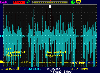
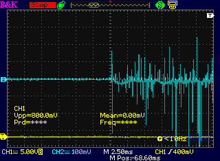
 Power Supply/Battery Current via DC current clamp: Vertical scale is
100 amps per division.
Power Supply/Battery Current via DC current clamp: Vertical scale is
100 amps per division.
The 200 amp cutoff is
apparently a more approximate spec as made than expected, but it works.
Most 'on' pulses seem to stop at 100 amps, but a few go up
to 350 amps, and energy return pulses go down even beyond 400 amps.
Left: the overall 7Hz pattern, with a pulse duty
cycle of about 85%(?)
Middle: Beginning of the "on" section expanded 10x
Right: expanded another 50x.
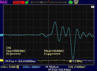
An interesting feature is the high return currents as the
coils are switched off, apparently higher current than the input
current (but probably of shorter duration). Someone mentioned that the
return spikes would be about (or exactly?) twice as large as the
original current spikes. Apparently true for current as well as for
voltage... but wouldn't that make more power returning than entering?
The energy return coil
still gets hot rapidly. Now if I had only examined these waveforms with
the original analog speed control differences might be evident. Maybe
I'll try looking at that later.
Other
"Green" Electric Equipment Projects
Peltier Module / Thermoelectric Cooling
With the old 8.5 amp peltier module, it didn't seem to
make a big difference how fast the fan was running to carry off the
heat. With the new 15 amp one, it definitely cools better with the fan
on higher speed. With the internal fan and the larger peltier, the
whole fridge is now cooler, mostly 7 or 8 degrees C instead of 10 or
higher toward the far end, with the area near the ice tray being around
5 or 6, which it still is. (Lower winter room temperatures sometimes
lower that to about 4°.)
That brings us back to my desire for a quiet large
evacuated tube radiator, which would have sufficient cooling surfaces
to operate without a fan. I talked with someone I knew involved with
refrigeration. He said he had a double vacuum pump that would create
very high levels of vacuum. But if I had water in the tube, it would
evaporate and come out as water inside the pump, doing the pump no good
and leaving no water to boil in the pipe. I hadn't been able to make
the steam-out of the air work, and now I was disillusioned about my
alternative idea of simply sucking out the air.
But I soon had another thought. If one put the pipe with
the
water in the freezer, the water would freeze. Then the air could be
sucked out without sucking out the water. Now all I need is time to put
together a pipe with some sort of pinch-off end or other means of
sealing it, and go to my friend's shop and see how to best do it. (Does
he have a freezer?)
Electricity Generation
Atmospheric Charge Energy
Recap - What and from Where is Atmospheric Charge Energy?
The Earth is a giant dynamo with 200 million amps flowing
continuously around it. It might seem only natural that such current
provides the known electrical charges in the air, which voltage levels
may rise on a clear day by almost +100 volts per meter of altitude. So,
if the Earth is neutral in charge, there are more and more electron
deficient ions in the air as one ascends. This is what can electrocute
linemen touching unconnected power lines from tall, grounded towers,
and cause big sparks from cables hung from helicopters. Furthermore,
that voltage is an average. There is also a large AC component to it,
ebbing and flowing, according to Tesla, and to Moray it sounded through
headphones on an unconnected telegraph line like static, pulsating
rather like crashing waves, with big peaks followed by decreasing ones
until the next big one comes along. On a stormy day, moisture in the
air multiplies the effects by orders of magnitude, and the DC charge is
often reversed, with negatives at or above the clouds. Lightning is the
sudden discharge of the turbulent, highly charged air either to ground
or to a "nearby" air space with a different charge. But some of the
atmospheric electricity that causes lightning is always present, and
can be harvested in controlled, useful ways.
It is well known that a simple circuit of diodes and
capacitors can capture the ions that happen across its antenna,
producing a small current that can gradually charge a cellphone. (It
can also harvest from nearby power lines and radio signals.) A huge
antenna such as Ion Energy Group's is required to harvest much
power.
But it appears that an oscillating circuit such as those
made by TH Moray from 1926 to 1929, probably resonating with natural
frequencies of the energies, can multiply the energy, bringing the ions
to the antenna and generating vastly greater quantities of useful
electricity, apparently at ultrasonic or RF frequencies - LF, MF and
maybe HF. The difference is between milliwatts and kilowatts. A good
number of testimonials written at the time demonstrates that it did
indeed work as stated, leaving no credible possibility of a hoax. [A
compilation of them are here: http://svpvril.com/Moray.html
-- "Of the great number of learned men who have seen or heard of
Moray's work, not one of them has ever been able to disprove his
theories, claims and discoveries."]
This apparently first and very successful resonant
circuit atmospheric energy harvester used some unique components in his
circuit, and also never fully explained how his device worked. For
these reasons, no one ever managed to copy his design. One key device
was the world's first semiconductor diodes, made from "Swedish rock"
germanium, which even Moray, a mineralogy and crystallography materials
expert, was never able to adequately synthesize once he ran short of
the original natural material. Another device was his specially made
vacuum tubes with unique sounding operation that I won't attempt to
describe here. (He made three models of the tubes, that all worked in
the energy devices.) Moray described
the energy being harvested as "radiant energy" as he was aware that it
was radiant energy that ionized the air, but it seems he thought it was
the atmospheric
ions he was harvesting.
Soon corrupt interests sabotaged Moray's efforts to patent
anything at all, and tried to have him killed, apparently on three
occasions. Moray had become
suspicious and carried
a small gun, and he evidently kept his wits about him and was a very
good shot, because he came out alive on all three occasions. Finally a
jealous
person smashed his machine, and the work came to a sudden inglorious
end. (Moray went on, among other fascinating projects, to invent/design
improved (vacuum tube) radio receivers and amplifiers for well known
companies such as General Electric and Sylvania, which units graced
many homes up until the early to mid 1960.s when the first small,
portable Japanese "transistor radios" came out, followed by more modern
solid state stereo equipment in the late 1960.s. But I digress.)
A researcher tried to draw Moray's energy harvesting
circuit schematic from memory from seeing it in the patent application.
(Moray's patent applications were denied on specious grounds, and the
contents of the application envelopes mysteriously disappeared from the
patent office.)
Of course the chances of it being mostly correct are
small. The person
didn't know what the bimetallic lead/silver piece was for, and its
placement between two capacitors (according to his memory) is even more
puzzling. (Doubtless all explained in the patent.) One recognizes
a potential L-C oscillator involving the two tubes with the lower coil
and switch, which (having no source of power until the unit was
working), had to be "stroked" with a magnet to get it started, at least
in the early units.
Today's problem is that while atmospheric charges are
better
known, the resonant oscillations technology for harvesting them
effectively has been little known or misunderstood and has never
spread. Only recently with the advent of the internet has it started to
become somewhat easier to separate facts from myths, and to find
nuggets of information about Moray's work and other more recent
apparently successful work. Still those with
nothing real to offer, perhaps some of them shills for the corrupt,
seem to shovel out all the disinformation they can, and by perpetrating
so many convincing and unconvincing hoaxes, make it seem like it must
all be hoaxes.
Yet we understand that the atmosphere is in fact full of
ionic energy. And that Moray's energy harvesting device worked to
the extent of at least several kilowatts, day or night. Today we have a
wide variety of electronic devices that were unavailable to Moray. One
person described the tubes as "oscillating tubes", and there are lots
of ways to make an oscillator. We have both germanium and silicon
diodes readily available, and active rectification if extra-low forward
voltage drop proves somehow instrumental to the harvesting. Surely in
the 21st century, Moray's pioneering work can be explored and expanded
upon. Even if there were no other, this well known - if not well
understood - form of plentiful free energy is all around us, seemingly
just waiting for appropriate circuits to be invented or reinvented in
order to harvest it!
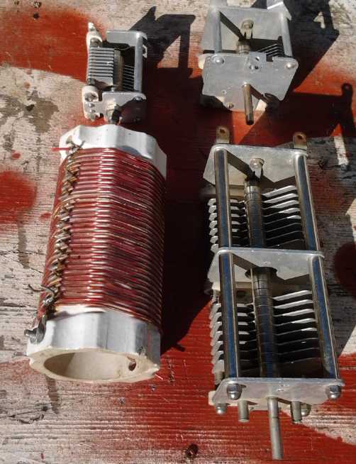
Correction: The air-core coil I got last month (left) is about
25 microHenries, not 25 nanoHenries. (Small slip, BIG 1000x difference
when
designing a circuit!)
On the 6th I searched youtube for "Atmospheric
Electricity" and
found a channel called "LaserSaber", who had done some experiments in
that area, using a hexcopter to lift wire high up into the air. The
most interesting video was one where because of a high voltage
electrostatic motor (with considerable torque!) that he had built and
shown on youtube, he was invited
to visit Ion Power Group which has been working on harnessing
atmospheric energy for 10 years in Florida. I was impressed with
several things,
not the least of which was the many kilovolts coming down from the 4
antenna wires 130 feet up, strung between 4 poles in a very large
square. The danger of working with such high voltages was impressed on
me many times in the video, from heavy rubber gloves, to 6" long
ceramic
insulators, to a 1000 to 1 reduction voltage probe (reading ~9 = 9000
volts, or ~12 = 12000 another time),
to a continuous thick arc bridging a gap of nearly an inch on a
turbulent day, to 4' long
sticks used to hold and connect wires, to a giant shower of sparks
that lit the room from connecting something wrong. And they spoke of
250000
volts on a stormy day!
But they were using passive
collection. Their web site mentioned the collection of energy
"skyrockets by many orders of magnitude" when the atmosphere is
disturbed, but not that they had any
thought of electromagnetically disturbing it to get the same effect.
They had
big, high antenna lines and got energy, and used some streaming wires
with graphene that formed
micro-spikes that would multiply their charge collection by 10 via the
corona effect, but it
still wasn't the sort of high energy Moray was collecting with what
appeared to be resonant circuits -- except on stormy days, when they
got up to over a kilowatt. Moray got several kilowatts any day.
I plan to try out Moray's route...
with considerably more caution than I was thinking of and a much
smaller, lower antenna. (an
aluminum plate, tied to my chimney about 40' up?) Evidently it could
still make
potentially lethal voltages. But if I can make the resonance technique
work, it should still produce very useful power instead of milliwatts.
It occurred to me that a good place to start might be to
connect a diode or a diode bridge and a microampmeter (big needle, -50
to +50 µAmps) between an antenna and a ground wire and see what
DC current might flow. I could also hook the oscilloscope in there and
see the actual voltage waveforms instant to instant. With all the
nearly "mystical" talk about germanium, I got four 1N34 germanium
diodes for the bridge. From what I've been seeing the difference
between .3v (Ge) and .7v (Si) forward drop should be a drop in the
bucket. And
yet...
Then there's spark gaps. Apparently blue sparkles could be
seen running down Moray's "Swedish stone" germanium diodes. Did the
germanium crystals in his stones form tiny spark gaps? Is a spark gap a
diode? Maybe sort of. Depending how it's made, it
should be more prone to arcing in one direction of voltage than the
other,
again by the corona effect. There's no current at all until the arc
begins. (Then when current starts to flow, does the forward voltage
drop drop to zero?)
But I decided to make a spark gap as a safety device to
protect both my circuits and myself against overvoltage. On the 9th I
came
up with a tentative plan for a one: an outside surround of metal such
as a round or square pipe or tube, with a gold surface, perhaps simply
plated with gold, arcing to something like a stainless steel sewing
needle. The needle might be placed in-line, parallel, with the surround
metal, just an 8th, 16th or 32nd of an inch (or whatever seems to work
at a desirable voltage) from one edge. The surround metal (anode) goes
to the antenna at the top, and the needle (cathode) is grounded. Where
most metals will corrode and form an oxide
layer of some sort under positive voltage (anode) conditions that will
hinder arcing, gold, almost alone, is very difficult to oxidize. (I
wonder if my ~2004 Caswell Plating gold brush plating solution will
still work?) The metal tube could be inside an insulating plastic or
ceramic pipe, and the needle could be mounted in a big ceramic block...
after seeing all the arcs and sparks at Ion Energy's facility, I want
to try hard not to electrocute myself. Or get the radiation(?) burns
that Moray got on his hands, that were probably the same as those I
seemed to be being warned of in a dream. Maybe I should make some
ceramic parts first in my mini-kiln. And maybe the antenna will go next
after the spark gap to a big knife switch... enclosed in something...
that I operate from a distance with a plastic rod. It can also have a
shorting switch to ground to prevent high voltage from getting to the
circuits as the antenna is switched in - assuming I always
remember to turn the short on before activating the antenna. But
relying on memory for the switch-on sequence isn't a reliable
technique. Maybe if opening the knife switch automatically closes the
shorting switch. I think I like that idea. Well, doubtless I'd have to
make my own switches regardless to get that to happen!
And yet, from the passive designs I've seen, the voltage
builds quite gradually in the circuit when the antenna is connected.
Should it not be possible to make, eg, a 12 volt DC output unit, and
the oscillator shuts off momentarily or something shunts off the excess
if the voltage gets too high? Except at the spark gap and the knife
switch, with the circuit turned on there should be no high voltages. An
inverter can be used to change the 12 VDC to 120 VAC/60 Hz as required.
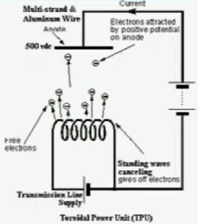
On youtube I found an explanation of sorts for active use
of a "spark gap" of sorts... a "Toroidal Power Unit" ("TPU") was shown
as being kind of like a vacuum tube effect with no vacuum, the
electrons flying toward a high voltage 'plus' plate.
I decided to use an "extension cord", a cable having an
outer sheath, for the antenna leed wire. I could drill a hole in the
roof near the chimney and feed it through. First I selected an aluminum
plate from my collection for the antenna. Next question was, what to
use for an insulated "mast" to hold up the antenna. I would tie this to
the chimney. (Say, how come I've never heard of people getting shocks
putting up or hooking up, eg, a TV antenna?)
Then on the 9th I thought that if the Ion Power Group was
using spikey bits of graphene not only to make lots of little spikes
but also to increase surface collection area in general, maybe an
aluminum window screen - lots of fine wires - would be better than a
plate. Or even such a screen with some graphite fiber wrapped around it?
On the 10th a considerable search with some clean-up found
the ±50µAmp meter, and a cable for the antenna connection,
but not the big knife switch. Further searching over the next couple of
days was to no avail. Who would ever dream I'd ever actually want to
use that antique?
Soon I decided I'd have to make my own special double
safety switch: Opening the antenna knife switch would automatically
close the safety ground-short switch to protect the electronics and
perhaps myself. Only once the antenna switch was reclosed could the
ground short switch be opened, allowing the antenna voltage to rise to
power up the circuit. The electronics itself would have some means of
preventing the antenna voltage from rising too high. So the electronics
need not be designed for high voltages, except perhaps for the
oscillator to 'stir' the air.
Then I realized that the antenna never needed to be
disconnected. If it was grounded everything was safe. It just needed a
simple knife switch, but to ground, not to the electronics, which could
always remain connected. I still couldn't find it. Perhaps I actually
threw out something that looked sort of interesting, just because I
couldn't think of a use for it? On the 12th I gave up and bought a new
large size switch, a battery switch from an automotive place. It's
probably better because the wires (in particular the antenna wire) are
enclosed.
 On the 14th I
went to buy an aluminum screen. But I got a
thin, solid aluminum "gutter guard" instead. It was bigger in area than
my aluminum plate but it had holes to increase the surface area and to
let some wind go through. I thought about the idea of insulating it (it
was already painted), more particularly with a high dielectric constant
insulation. On the 15th I thought of the static cling of transparent
tape. Since I couldn't see wrapping it with countless skinny pieces of
that, I used packaging tape, which also has a lot of static cling. If
it makes all that static as it's unwound, surely it has the right
characteristics? (So much for the holes in the aluminum!) Then I
mounted this plate on a 5 foot PVC pole, clamped that to a piece of
wood, connected the cable, and tied it to the chimney at the peak of
the roof with a few wraps of rope, about 40' up from the ground. I
drilled a 3/8" hole through the roof, next to the peak and next to the
chimney, and pushed the cable through, into the attic space. The next
day I donned gear and ventured into the attic (full of
blown-in-fiberglass dust, cellulose fiber dust, rat droppings et al)
and ran the wire through to the solar equipment closet below.
On the 14th I
went to buy an aluminum screen. But I got a
thin, solid aluminum "gutter guard" instead. It was bigger in area than
my aluminum plate but it had holes to increase the surface area and to
let some wind go through. I thought about the idea of insulating it (it
was already painted), more particularly with a high dielectric constant
insulation. On the 15th I thought of the static cling of transparent
tape. Since I couldn't see wrapping it with countless skinny pieces of
that, I used packaging tape, which also has a lot of static cling. If
it makes all that static as it's unwound, surely it has the right
characteristics? (So much for the holes in the aluminum!) Then I
mounted this plate on a 5 foot PVC pole, clamped that to a piece of
wood, connected the cable, and tied it to the chimney at the peak of
the roof with a few wraps of rope, about 40' up from the ground. I
drilled a 3/8" hole through the roof, next to the peak and next to the
chimney, and pushed the cable through, into the attic space. The next
day I donned gear and ventured into the attic (full of
blown-in-fiberglass dust, cellulose fiber dust, rat droppings et al)
and ran the wire through to the solar equipment closet below.
Cleaning the closet occupied the next day's work session.
It was full of plaster and drywall compound from fixing the wall when I
first did the solar stuff along with crap from the holes for wires into
the attic, some firebricks and other bricks I had set dry cell
batteries on for fire safety, batteries lying around, and various bits
of electrical stuff, both on the floor and the shelves. I did a lot of
vacuuming. None of it my favorite work. But I think I'm digressing from
the story here. Comes of writing late at night.
 On the 18th I
formed a couple of ceramic clay pieces for
an insulator to hold the spark gap. I left them to dry overnight, then
fired them in the mini kiln.
On the 18th I
formed a couple of ceramic clay pieces for
an insulator to hold the spark gap. I left them to dry overnight, then
fired them in the mini kiln.
On
the 19th I voted, marking my ballot 3 - 4 - 1 - 2 in my order of
preference for the candidates. No 'illiterate's X' ballots for me!
Hopefully it'll at least give the vote counters something to think
about!
Then I contrived to mount the spark gap and the antenna
grounding switch on the wall in the closet, and connected the antenna.
Then next day I added a couple of wires to connect to a nearby circuit
and put in a small shelf to hold a circuit 'breadboard' to try things
out. I measured the voltages from the antenna: .34 VAC, and -.012 to
-.02 VDC. Not only were the voltages trivial, the DC component was
backward compared to expectations. Quick attempts to hook up diodes and
2.2µF capacitors seemed to kill it. It turned out to be the
2.2µF ceramic capacitors, which *should* have virtually no
leakage. A .1µF capacitor charged up so slowly to over 1/2 a volt
(still backward polarity, with the diode either way around!), that
simply connecting the voltmeter - doubtless quite a high impedance unit
- caused the voltage to rapidly start dropping instead of rising.
Variations on the circuit seemed just as futile. Had I made a mistake
by insulating the antenna? It certainly appeared, as many have found,
that a simple diode-capacitor circuit doesn't bring in much power.
Others have had better (less trivial?) success on youtube. The
possibility remained that a resonant oscillator would revolutionize the
picture.
 The next morning (21st) I looked again at the "Tesla Cult" circuit.
(but remember "ground rod south" was replaced by "antenna".) My antenna
voltage of only .34 VAC was hardly enough to overcome the forward
voltage drops of semiconductors. It didn't even seem to matter which
way around the 1N34 germanium diode was. But the coil with the tap, the
"variable air core transformer", would magnify the voltage by the ratio
of:
The next morning (21st) I looked again at the "Tesla Cult" circuit.
(but remember "ground rod south" was replaced by "antenna".) My antenna
voltage of only .34 VAC was hardly enough to overcome the forward
voltage drops of semiconductors. It didn't even seem to matter which
way around the 1N34 germanium diode was. But the coil with the tap, the
"variable air core transformer", would magnify the voltage by the ratio
of:
the whole coil
---------------------
the tapped portion.
If that was (say) 6 to 1, the tap 5/6 of the way to the bottom, it
would be .34v * 6 = 2.04v making the voltage high enough to work with.
The already feeble current would be similarly decreased by 6x, but it
seemed the voltage was too low to make good use of whatever current
there was anyway, so it's probably all gain. Here was the first key:
the coil makes for not just a resonant circuit, but an AC/RF voltage
multiplier. Here we get the impression that it may be more the AC
component of the atmospheric ions that is important than the DC one,
which can't be amplified by a transformer. But maybe it's the combo.
But when I connected the coil, the AC voltage dropped to zero. That
suggested a low frequency rather than RF.
Being busy with other things, it wasn't until the 31st I
brought over the
oscilloscope to better see what was coming in. With no other connection
to the antenna, the DC component was pretty much imperceptible and the
AC component was just mostly 60 Hz hum, .4V peak to peak - no surprise
in a wired house. There was another sinusoidal waveform on top of it at
about 1MHz, but only about 20mV peak to peak. This could have been a
nearby AM radio station - in fact the signal's amplitude modulated
probably about like music playing. Something else briefly appeared at
regular short intervals that seemed to be about 10 MHz, but it seemed
to be synced to the radio station. Nothing seemed anything like a
random sort of atmospheric noise, but it had an 'artificial' look to
it. I saw no lightning from distant thunderstorms but then it was
October, and we get less lightning on the west coast than anywhere else
on Earth. Where then was this atmospheric energy?
Nothing ventured nothing gained, it was time to breadboard
the oscillator. I thought I'd start with Tesla Cult's circuit since it
was simple. I plunked in the components and connection wires. Nothing
seemed to happen. That was as far as I got. Next will be a real
oscillator with a tuning capacitor to vary the frequency and a battery
to provide initial power to make sure it's working.
The test setup.
The red shielded wire comes from the antenna. The black wire
is grounded at an electrical outlet. The spark gap to ground is
to help protect circuits and ensure safety should high voltages
actually become present if it works. Likewise, the red switch
shorts the antenna to ground. I screwed a piece of wood into
a board in the closet wall to make a small shelf for trying out
circuits.
(The wires on the far right are from the solar PV panels and the
black box is the Zahn DC to DC converter that converts the solar
panels' output to 14.0 volts to charge NiMH and PbPb batteries and
for the 12V receptacles around the house, so far used for LED lights
and the Peltier fridge.)
In early November I read
that Moray's later energy units worked in locations where they couldn't
be tapping atmospheric energy, and without an antenna or a ground. It
seems he must actually have been tapping "lambda ray"/"short space
ray"/"VHE gamma ray"/"zero point" (surely all the same thing) energy
after all. Why would he get radiation burns from atmospheric
electricity?
Frankly as I write, I realize that I still have virtually
no success and far more questions than answers. Is atmospheric energy
worth pursuing or just a curiosity? Or is the seemingly elusive lambda
ray energy the only practical pursuit along these lines?
I think that a spark gap, like Moray's sparking mineral
diodes and like the "TPU" circuit diagram above, has some valuable if
not fundamental purpose in capturing lambda ray energy. But if so, just
how and where should it be employed? Perhaps the "TPU" illustration is
a clue - maybe it just makes a high frequency, high voltage diode?
Well, perhaps I'll try a bare metal antenna next, as the
dielectric coated one doesn't seem to do much of anything. One thing
sure: if anything I try yields success measured in tens of watts or
better, I'll document every aspect well so hopefully everyone can
achieve similar results.
Electricity Storage
-
Turquoise Battery Project Etc.
Lead? Lead?
 On the 30th I was thinking about
the nickel-nickel cells that keep having more self discharge than
nickel-manganese, which are double the voltage. Something I don't
understand is going on there. Then I thought of zinc,
that elusive metal that works so well... except for gradually
dissolving during discharge (and sometimes shorting the cell) and so
giving short cycle life.
On the 30th I was thinking about
the nickel-nickel cells that keep having more self discharge than
nickel-manganese, which are double the voltage. Something I don't
understand is going on there. Then I thought of zinc,
that elusive metal that works so well... except for gradually
dissolving during discharge (and sometimes shorting the cell) and so
giving short cycle life.
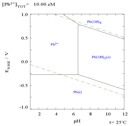
Then I thought of lead, similar to zinc in some ways, but
it doesn't dissolve even in sulfuric acid. I looked again at the
reduction potentials diagram. (the one that had steered me so wrong in
the past by having a wrong value printed on it.) In sulfuric acid,
metallic lead discharges to lead sulfate, PbSO4. This substance
gradually forms larger, non-conductive crystals that can't be
recharged, helping to give lead-acid batteries their well known limited
cycle life.
But in alkali the chart shows it discharging to lead
oxide, PbO. (or more likely to lead hydroxide Pb(OH)2 per the Pourbaix
diagram
below. It make little difference which it is.) This (surely?) won't
have such a problem. And the reaction
chart is dead simple - no branching tree or dissolved ion or
non-conductive states. (We know from lead-acid that batteries that PbO2
(or, surely, Pb(OH)4) is a conductor.) So unlike nickel-iron, I would
think it
shouldn't have to be used at pH 14 to prevent irreversible corrosion to
a non-conductive oxide form. It should thus have a very long cycle
life. As we all know lead has a high molecular weight (207.2), which
does little good for energy density (theoretically 259 WH/Kg for the
metal)... but might it work for me better than things I've tried? Might
nickel-lead provide a simple chemistry for small scale production which
has eluded me so far?
The reaction voltage of metallic lead to valence 2 is very
low in acid. But in alkali it's over 1/2 a volt. A nickel-lead cell in
KCl solution at pH 12-13 should work with a voltage of about +.85 -
-.54 = 1.39 volts, or maybe somewhat less. If it worked well, I'd be
farther ahead than I have been so far!
I decided the thing to do would be to take apart a
lead-acid battery and disassemble some of the plates. I have a simple
candidate in a small one about the size of a 'D' cell that has been
sitting around for years and has just turned up from a dusty cupboard.
Or maybe just find a chunk of lead for a quick experiment.
One is tempted to look above lead on the periodic table
for a lighter element in the same column. But the next one up is tin,
which has many soluble reactions. Above that are germanium, then
silicon, then carbon. Carbon, and probably silicon, wouldn't oxidize.
My mind balks at the idea that germanium might work even without
checking it out. Lead seems to be unique.
 A separate possibly
useful lead reaction is Pb(OH)4 to Pb(OH)2 for
the positive electrode. It moves 2 electrons where simple NiOOH to
NiOHOH only moves 1. In alkali the theoretical reaction voltage is a
little lower than NiOOH. The high atomic weight gives it a
theoretical energy density of just 200 WH/Kg (at pH 12, counting the
atomic
weight of three 'OH's), versus 289 for the NiOOH (at pH 14).
A separate possibly
useful lead reaction is Pb(OH)4 to Pb(OH)2 for
the positive electrode. It moves 2 electrons where simple NiOOH to
NiOHOH only moves 1. In alkali the theoretical reaction voltage is a
little lower than NiOOH. The high atomic weight gives it a
theoretical energy density of just 200 WH/Kg (at pH 12, counting the
atomic
weight of three 'OH's), versus 289 for the NiOOH (at pH 14).
There are two ways this might be useful in place
of NiOOH.
The first is if it has significantly better percent utilization
of the
atoms. Then it might outperform the nickel, which I've heard somewhere
gets around 90 WH/Kg in actual use. The second is if a solid
piece of
lead reacts on the surface without the reaction penetrating deeper, ie
if the oxide layer that forms is solid and doesn't dissolve. In
that case, a lead
(Pb) wire in the positrode wouldn't dissolve, and the current collector
and connection wires can be lead (as they are in lead-acid batteries)
instead of graphite. That's not lighter but it's simpler to make and
promises better internal and external connections. (Potentially lead
leeds
would work for nickel hydroxide electrode current collectors in KCl,
too. IF
it works that way.)
But with decreasing pH, while still on the alkaline side,
the lead voltage rises more gradually than that of the nickel types, so
the cell voltage will be somewhat lower. Since that probably means both
lower voltage and lower amp-hours for lead, and as it seems to be
finding a good negative electrode I'm really having trouble with, I'll
probably leave the lead positrode idea well enough alone. Except maybe
I'll try out a lead terminal wire and see if it stands or dissolves. It
would be much easier to seal a wire through the case than the graphite
sheets.
Pulse Charging
for Lead-Acid Batteries
I've experimented a lot with using sodium sulfate to help
restore lead-acid batteries. Another thing to do is to try using a high
frequency "pulse charging" charger, which as I have discovered often
makes the difference. The merchant said he’s brought more 'dead'
batteries back to life with the "Xtreme Charge" charger he sells than
anything. It’s only 2 amps, but it helps gradually break up the lead
sulfate crystals that passivate the plates.
Be sure to get one that actually does only pulse charging,
or at least allows it as a user selectable option. I recently bought
two cheap ones that say "pulse charging" on them, but they only do
pulse charging if they decide to - I can’t make them do it, and
indeed they have never entered the pulse charging mode they claim to
have on any battery I’ve tried.
 The top “Xxtreme Charge” is a good
model that does strictly high frequency pulse charging. (bought locally
at “Battery Direct”)
The top “Xxtreme Charge” is a good
model that does strictly high frequency pulse charging. (bought locally
at “Battery Direct”)
Its biggest failing is that it claims badly discharged batteries are
"bad" and won't start charging them. Use another charger to get them
started.
The bottom “genius”(?!?) one
claims it has pulse charge, but it won’t go into pulse charge mode and
so it's pretty useless.
It claims it'll go into pulse charge mode when it
detects the need to do so... but how can it really know?
It doesn't do it or let me select it on any crappy battery I've tried.
(bought at Canadian Tire)
...It's another "would have been useful" product turned into crap by
another manufacturer not disclosing useful information
(like what material something's made of, etc) or (as in this case) not
allowing the purchaser to make his own choices about how to use it.
Why?
http://www.TurquoiseEnergy.com
Victoria BC Canada
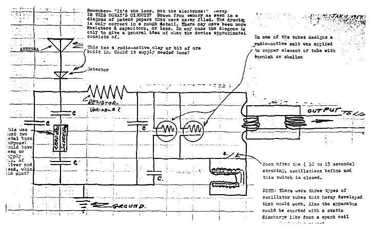
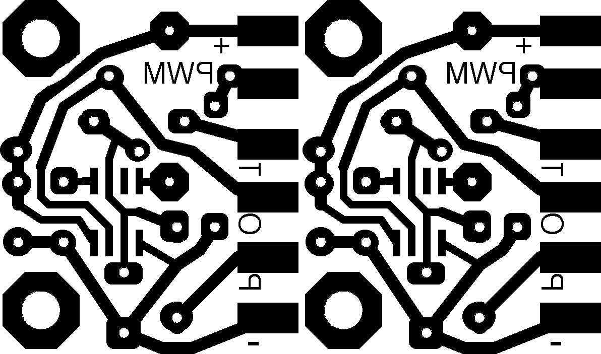