Turquoise
Energy Ltd. News #94
covering November 2015 (posted December 2nd)
Victoria BC
by Craig Carmichael
www.TurquoiseEnergy.com
= www.ElectricCaik.com
= www.ElectricHubcap.com
= www.ElectricWeel.com
Highlights:
- Theory and Methods of Generating Electricity from Lambda Rays (AKA
"VHE
Gamma Rays") (See:
Month in Brief, Electricity Generation)
- Variably Engaging Drive Rod: a new type of variable torque
converter? (See: Month in Brief, Electric Transport)
Month In Brief
(Project Summaries)
- Lambda Ray Converter - Unipolar Motor Controller - Microcontroller
based unipolar controller? - Variably Engaging Drive Rod Variable
Torque Converter?
In Passing
(Miscellaneous topics, editorial comments & opinionated rants)
- Energy is everywhere; Where are we? - Small space update: Pluto,
Ceres, Comet 67P
- Obstruction of Democracy:
social treason.
- In Depth Project Reports -
Electric Transport - Electric Hubcap Motor Systems
* Unipolar Motor Controller: pulse speed control input to improve
performance.
* Coil heating problem became diode heating problem with new coil.
* Variable Crank Rod Gear (Another possible type of variable torque
converter?
- FWIW)
Other "Green"
Electric Equipment Projects (no reports)
Electricity Generation
* Lambda Ray Energy Converter:
- "Well known" but unexplained electrical "DC kick" phenomenon is
doubtless indicative of simple lambda ray
energy conversion. This is the starting point!
- Multiple frequency resonating oscillations "kick the kick of
the kick" up
to powerful (even destructive) levels.
- Construction - Control Circuit Schematic & PCB Files -
Programming Strategy
- Notes on Steven Mark e-mails compilation (the source of much
info)
Electricity Storage - Turquoise Battery
Project (NiMn, NiNi), etc. (no reports)
No Project Reports on: CNC
gardening/farming machine, Electric Weel, reluctance motors, battery
making, aquaponics,
Magnet motor project.
November in Brief
This was another month that at first seemed like little
would be done.
With the cold et al I didn't get TE News #93 out until the 7th, and
soon enough the first 1/3 of the month was over. But then things
started to
get interesting. I didn't get very far on the motor controller, but I
learned a lot about radiant energy collection, and I thought up a
potential new type of torque converter, and 'month in brief' is less
than brief.
Atmospheric Energy
Lambda Ray Converter
The atmospheric energy harvesting ideas of the last month
or two seemed to evaporate
when I read further about Dr. T. H. Moray's machines. It seems he made
a
number of them. The design evolved,
and later ones didn't need an elevated antenna, only a good ground
connection. The antenna could be replaced by a small internal metal
collector plate, and in fact the unit would even work in an enclosed
space. That meant Moray couldn't be harvesting atmospheric charged ions.
That's not to say of course that atmospheric ion energy
doesn't exist. And Ion Energy Group has managed to magnify the ion
capture by ten with their microtextured graphene streamers, and
'LaserSaber's
[youtube channel name] high voltage electrostatic motors run quite well
off it. But getting a kilowatt on a reliable basis seems elusive so far
and still requires an extensive elevated antenna installation. My "high
dielectric constant insulated antenna" seemed to be about the worst
idea - at least, I seemed to get virtually nothing from it, where a
bare wire at least gradually builds a charge. Atmospheric energy may
further evolve, but so far it looks like an impractical field.
Moray had to be collecting "lambda ray" radiant energy,
and after reading some
nuclear theory and experiments by Dr. Gustav Le Bon, a contemporary of
Tesla, he eventually came to that very conclusion himself: that surging
electromagnetic
rays
"from
beyond
the
gamma
ray
bands" were the energy
source of his machines. The electromagnetic spectrum didn't end at
gamma rays after all. Did anyone ever say it did? But there was no
detector for such incredibly high frequency, incredibly high energy yet
somehow elusive and inoffensive rays, so he had no means of
proving their existence or of quantifying and qualifying them.
But as fire was used for many millenia without
having a scientific understanding of it, want of even a reasonable
theory hasn't prevented at least a few
other
people
from converting and using [lambda] 'radiant' energy over the last
century - often ascribing the energy source to some mystic sounding,
scientifically unapproachable, explanation.
So, after two years, that brought me back to "lambda ray
collection", or rather, "energy conversion" from lambda band photons to
electrons. It's similar in principle to common solar PV, but uses a
completely different sort of "panel" for a wholly different band of the
electromagnetic spectrum. Moray saw it as 'surging' and noted some
directional preferences apparently related to the position of the sun,
but some considerable amount is seemingly always available anywhere,
day and night.
Cosmic _____ Background
radiation bands, left to right:
Lambda (my rough estimates/guesses), Gamma, X-ray,
Ultra-violet & Visible, Infra-red, Microwave, Radio
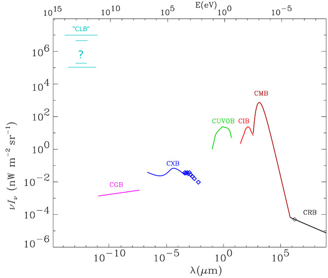 Perhaps this a
good place to summarize the
things that fit
together to form the basic theory as I see it.
Perhaps this a
good place to summarize the
things that fit
together to form the basic theory as I see it.
First, what is this unseen energy that a number of people over the
decades seem to have harvested?
* The "lambda ray" band or bands
was suspected, to some extent known, since Moray in the 1920s
determined his energy must be coming from rays "beyond the gamma ray
bands". But there was no detector to prove unequivocally that they
existed.
* If they weren't before, these ultra-ultra short rays were finally
detected and identified in 2007 by the Fermi Gamma Ray Space
Telescope as rays at up to 2.7*10^27 Hz, yielding 10
trillion
electron volts per photon, perhaps 10000 times
higher frequency and energy than the (poorly defined) top of the gamma
ray band. And their radiative effects are quite different. But they
were, IMHO misleadingly, dubbed "very high energy gamma rays" or "VHE
gamma rays" anyway. (And ultra-violet is "VHE infra-red"?)
As photons in the gamma ray bands were found by the
Chandra
and the
Fermi space telescopes unexpectedly to originate, unevenly, from all
around the sky ('no direction looks dark to gamma ray eyes'), one
suspects the lambda rays probably likewise come from multiple if not
all
directions and are ubiquitous. But Moray noted a definite correlation
of intensity to
sun position, implying the sun may be a prime, or the prime, source in
proximity to this world. Certainly the sun provides most of
the rest of our energy.
And as each lambda band photon has
perhaps 100 to 100000 times the energy of a gamma ray photon (itself
considered highly energetic), it makes sense
that this previously "undetected" band probably contains far more
energy than all
other bands
combined.
* Since people have harvested the energy, and from a hint on Wikipedia,
I surmise that these rays not only come through Earth's atmosphere
undiminished, but that they ordinarily have few interactions with
matter, not
affecting living tissues and maybe even passing right through the
Earth. They not only exist, they are as far as known so far, available
at least to some good extent anywhere, any time. (They may also be
the undetected energy that makes radioactive elements/isotopes
radioactive. I'll retreat quickly from that subject!)
Then we get to the question of how to capture this "very high energy".
* One thing that apparently does cause lambda ray photons to
interact with
matter and release their energy is a sudden change of electrical
voltage in the matter they are passing through, such as in a copper
wire. It seems this effect was discovered accidentally, long ago, but
no one had a good explanation for it. Apparently it is well known in
power electrical
circles that whenever a DC circuit is suddenly switched on,
there is an extra "kick" of voltage, the "DC Kick", beyond the
supplied
voltage.
The fact that the "kick" must be electrical
energy beyond
what was supplied went unexplored (except by Tesla?) until Electrical
Engineer Steven Mark
started trying build a device to tap it (in the 1980s?).
It's that simple in essence. All
the 'free energy' generators have a commonality of certain features:
on-off switching and perpendicular coil arrangements with "collector
coils" of just a turn of two. But the variety
of devices created that apparently worked appears to indicate
it isn't rocket science.
* Lambda ray photons release their energy by creating even a whole
"shower"
of
electrons and positrons. These would be the source of the "DC Kick".
(Per
Wikipedia https://en.wikipedia.org/wiki/Electromagnetic_spectrum
- Table Electromagnetic radiation interaction with matter, or
the copy of it in TE News
#70. Significantly, the table recognizes the "very high energy"
[lambda] band as a separate spectral region beyond gamma rays.)
* Notably the devices by, or inspired by, Steven Mark, and even more
his writings, help us see how to harness the energy.
Mark ("I'm a great believer in understanding, not copying") took pains
to explain the essential workings of his "toroidal power units"
("TPU.s") in his e-mails. Electronic circuits generated at least three
separate carefully tuned "harmonic" switching
frequencies in coil segments distributed around a toroidal collection
wire, and when the pulses were right, there was a DC Kick on top of a
DC Kick on top of a DC Kick ("the furnace feeds itself more fuel"),
perhaps as much as cubing(?) the kick effect. This brings
about useful size energy conversions - or even destructively powerful
if not controlled.
That's it! That's the simple, or anyway explicable,
theory behind pulling radiant energy "out of thin air"... like a solar
panel
does, only differently. The powerful radiation has always been there,
but it's inconspicuous because it interacts so little with matter, and
it long went undetected. The right technique, resonant voltage
switching,
can convert it to electricity.
Of course answers lead to new questions, like why do the
rays
behave the way they do?, how dense are they in space really?,
is our sun the main source?, is there still another band beyond
lambda?, etcetera. We'll have to set the new questions aside for
now and stick with the "how to". The wiring layout and right angle
coil configurations are one part of the key. The other key, especially
for making the "triple kick" type of converter safe and reliable, is in
creating a fairly sophisticated pulse control unit.
BTW - An aspect that seems odd to me is that most of those
who
obtained electricity seem to have been describing high or radio
frequency
electricity as an output product (probably pulsed RF electricity, at
the oscillator frequency(s)), but mostly they don't seem to provide
that
explanation, as if they don't understand that part of the phenomenon
either. It's been called "cold electricity" and "dark electricity".
I've seen light bulbs, both fluorescent and incandescent, light up near
radio transmitters without their filaments specifically being lit,
similar to descriptions in some 'free energy receiver' demonstrations.
And
various people have sustained serious RF burns to their hands around
"free energy" receivers. When
even well known (again... well known in certain circles) aspects are
evidently mysterious to many of the makers,
is it any wonder a cohesive theory of the novel parts hasn't been
forthcoming?
Construction
I
first decided to attempt again to recreate a rather successful (in the
experimental sense) unit made by
Otto Sabljaric, tested and carefully documented by him and
Roberto Notte
in a 55 page document available on the web in PDF form
(otto_ronette_TPU_ECD-V1_0.pdf). This was in
turn said to be based on earlier units or designs by (especially)
electrical engineer Steven
Mark and (also) by Floyd Sweet. So I looked up Mark's name, and found
that Mark had presented the real info, the starting point for everyone!
The Otto unit was successfully replicated by a third party
that did a youtube
video about it, lending it further credibility. I had started on this
in
2013 but changed the control coils to my liking, which is probably why
the transistor blew. I didn't really get too far except to identify the
energy source as being the recently discovered rays (I thought that was
a pretty good accomplishment in itself!), then I got
sidetracked. But there was a voltage reading indicating
that it momentarily captured energy it hadn't taken from the power
supply. This time I initially decided to follow the document's design
fairly
closely, and if I got energy out of it, then I would start
modifying things to see how it could be improved.
On the 11th and 12th I made plastic spools and wound the 3
"control coils" for the device, and put them with the "collector coils"
made in November(?) 2013. It now needed a circuit board with 3
oscillators to generate 3 different frequencies, and 3 ultra-fast high
voltage MOSFET drivers for the control coils, and I also started that
on the 12th, beginning with combining single unit circuits done in 2013
onto one board.
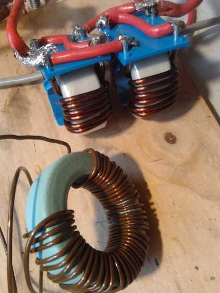
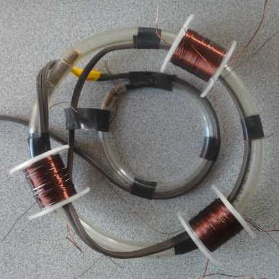 My incomplete "TPU" assembly, with air core
control
My incomplete "TPU" assembly, with air core
control
transformers wound on PVC plumbing pipe with
lexan shoulders,
set onto on "dual moebius toroidal" collector coil.
Then on the 17th to 19th I found and read a 63 page
compilation of e-mails written by the originator of it all, Steven
Mark, to a correspondent named Lindsay, loaded with the theory and
practice of making his original
"TPU.s". (Steven_Mark_TPU_compilation.pdf) Here the "DC kick"
phenomenon was described. (Otto spoke of the "kick" and
measured it in various lengths of wires of various metals, but he
didn't
explain it for us ignorant slobs who weren't told
about it in our electronics classes.)
Most interest in the
"kick" is (was) about it shortening the life of vacuum tube filaments,
and
electrocuting people in DC power stations. But Mark realized that
whatever its cause, this
was "free energy", and he figured if it could be repeated many times
per second and the effect "amplified", a large amount of energy could
be released as electricity. And he thought it would work because he
had once heard of some exploding GE color TV.s of a particular model
(doubtless a vacuum tubes model TV before transistors) that were known
to have caused very powerful magnetic effects when they exploded - like
bending and pulling nails out of nearby walls, which flew like bullets
at the TV set! They could not have
acquired or stored such energy as to do this from the wall socket, but
there are high voltages (even 25000 volts) being switched on and off at
various frequencies in a TV set with a color picture tube. If a system
is intentionally or inadvertently set
up to add the extra 'kick' voltages together the 'free energy' will
capture more of itself and multiply. Power, obviously very great or
destructive power, can then be derived from this excess charge. Various
strong electromagnetic effects have been noted besides production of
usable electricity - the TV being the most extreme example.
Mark's letters also mentioned US government
interference and threats to throw him in jail for his communications
explaining the theory and making of the units -- the very e-mails in
the above mentioned compilation. They were spying on everything he did.
He was
told his own invention that took him 15 years "is not your technology"!
(See TE News #84, In
Passing: Patent System: Far More Disgraceful than I Ever Dreamed! It
sounded just like that.) And shills seem to have been working
hard on line, lying to defame his character, since they can't deny his
devices work without being contradicted by qualified people who've seen
it. The social predators in charge are still hard at work to keep
cheap,
independent power out of everyones' hands. I hope Mark is okay.
After reading this highly educational material I started
to think I had a fair idea of how it all worked.
Especially it seemed the control circuit has to monitor and
be able to respond in an instant to any excess voltage buildup in the
coils, or one could have the exploding TV, or the destruction of his
device and all test equipment that Otto experienced. I decided that
instead of having three simple oscillators,
I'd use a microcontroller to generate the frequencies, constantly
monitor the
voltages, and shut down or skip a beat or two if things started to get
out of hand. Perhaps even a regulated output voltage can be obtained!
On the 19th I replaced the 555
timers in the circuit and on the half-done PCB with the MSP430G2553
microcontroller
that I had set up a software development system for, in May 2013
(TENews
#64). I had the PCB designed by the evening of the 20th, and I did some
clean up and a number of valuable changes after that. I attached a 6
pin header for a
"display-controller" (a serial interface device I made several of in
the 1980s with a 4 digit LED display and 6 pushbuttons) for readouts
and user input
to the microcontroller so the user can experiment with different things
without removing and reprogramming the chip for each one. Another 4 pin
header was to monitor the voltage and temperature of the unit, and I
added a power adapter socket. The only soldered connections to the
board are the coil wires. I managed to make it a single sided board
with just
two jumpers. Single sided, while less durable and reliable, is easier
to make at home as a prototype.
Some surface mount components I had ordered had arrived,
but
when I eyed
the tiny 1mm x 2mm capacitors I became unenthusiastic about trying to
work
with them. Also with the old through-hole types, one could run traces
underneath resistors and capacitors and effectively use them as
jumpers, so
especially for the single sided board I stuck with those. The only SMT
components I used were the IRS7307 mosfet pre-driver complementary
pairs, SOIC/SO-8 chips on the bottom of the board.
Here's where using a microcontroller to run everything is
incomparably better than any hardwired circuits: With a programming
strategy of starting up by sweeping the frequency bands with pulses and
measuring the kicks to find the best frequencies and resonances, the
unit should be able to automatically fine tune itself to at least
somewhat
different wire lengths and placements of collector loops and control
transformers, and to different simple resistive loads (lamp(s), heater,
toaster...). Then by monitoring the output voltage and adjusting pulses
accordingly, it should be able to maintain a regulated output voltage
to the load. If the load needs 60 Hz AC (electronics, etc.) or if it
needs straight DC, the frequencies coming out will have to be converted
to DC and then inverted to 60Hz AC. Inverters have become common
and relatively cheap.
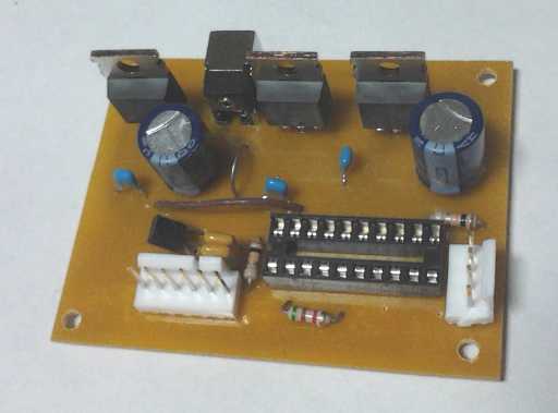 Lambda ray converter control board, with 3 high
speed mosfet coil/
Lambda ray converter control board, with 3 high
speed mosfet coil/
transformer drivers, power adapter socket, socket for microcontroller,
and header plugs for voltage and temperature readings (4-pin) and
user interface (6-pin). Pads to solder the control coil wires to are
underneath.
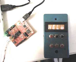
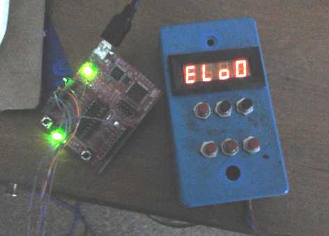
MSP430 development/programming board and my old display-controller,
which I'll connect to the lambda control/driver board (connects to the
6-pin header plug)
I did the coils/transformers Otto's way as air
core coils on plastic spools rather than Mark's apparently winding them
right on the toroid collector loop wires. But (imitating Floyd Sweet's
design) I
may try greatly increasing the number of turns in the secondaries to
induce
quite high voltages into the collector loop. That might give the
required "kick" to grab sufficient energy on each pulse, so that they
don't have to be added or multiplied together in resonance. That would
be easier to
control. But that's a major modification to the way it's been
successfully done before - at least by more recent, better documented
designs.
So there it is. I've followed a logical trail, come to
certain conclusions, and I'm designing and publishing about a unit that
should be superior to previous ones because it's better controlled.
Intellectually I understand that there's a "cosmic lambda ray
background radiation" (CLBR) band beyond the gamma ray band, much like
any other electromagnetic band. And that these photons are stopped and
release their copious energy when a voltage
in a wire is suddenly switched - perhaps because a sudden blip of
current flows during that switch, with the effects that has on the
whirling electrons within and the magnetic field around the wire.
I understand why most people have a hard time believing
this could be real. It's way off our radar screens of common experience
for a century, in spite of rumours that keep cropping up here and
there, now and then, but mostly with mystical sounding explanations
like "zero point energy", "orgone" or "vacuum energy" that are hard to
take seriously.
Free energy on the news one day never seems to be heard from again or
lead to any further developments. The obvious conclusion is that it
isn't real, that results have been faked for publicity to get on TV.
But there is
much evidence that working devices been ruthlessly suppressed each time
anyone
rediscovers how to make one.
I myself am having a hard time finding much emotional
conviction that it'll work. Until and unless I get some results I don't
see making any plans around it. (and maybe even then!) But everything
says it should work!
Considering the parts and materials involved, a mass-produced lambda
ray energy converter as I see it should cost much less than my latest
257$ electricity bill for just one wintery month.
For more, please see the detailed report, and also TE News #69 and
#70 for some of the background from when I started and figured out
where the energy is from (and then dropped the project until recently).
Unipolar Motor Controller
This item (what else is new?) is holding progress in the
motor and motor systems development.
 I wound an
energy return coil on a ferrite toroid to try
out in the motor controller on the 12th. The #14 wire was much shorter
and ferrite should be good for the high frequency pulses, but this coil
seemed to get just about as hot as the iron core one. Perhaps the high
pulse currents were magnetically saturating the core? It didn't seem
very promising. As with the first coil, more return energy seemed to be
going into heating the coil than back to the power supply.
I wound an
energy return coil on a ferrite toroid to try
out in the motor controller on the 12th. The #14 wire was much shorter
and ferrite should be good for the high frequency pulses, but this coil
seemed to get just about as hot as the iron core one. Perhaps the high
pulse currents were magnetically saturating the core? It didn't seem
very promising. As with the first coil, more return energy seemed to be
going into heating the coil than back to the power supply.
I almost decided to give up on my "simpler" unipolar
motor controller with a lower power semiconductor component count, when
I was sent a link to some power inductors ("chokes") at mouser[.com].
They
were similar to but far less costly than similar units I had looked at
at digikey[.com], so I decided to try out the most suitable
looking one before giving up. (25$C)
When it arrived I found that somehow it had more
inductance in 6 or even 3 turns of wire than mine had in 35. I guess
the ferrite must be different. When I ran the motor, this energy return
coil hardly got warm. But instead, the energy return or flyback diodes
got hot rapidly, where before they had heated less and more slowly. And
the motor current, which I had expected would drop, stayed about the
same.
I wondered why this should be. It seemed to me almost as
if the choke was a short circuit and the diodes were shorting the
energy back through the motor coils. I wondered (again) if the high
current
spikes were saturating the ferrite core, and drastically reducing the
inductance of the coil at such high currents. I decided something to
try would be to order a couple more of the coils and put them in
parallel, to spread out the magnetism. I ended up ordering another one
the
same and 3 of a less costly but almost as high current model. (The 3
turned out to have larger ferrite cores. I haven't tried them yet.)
On December 1st I tried doubling up the coil (first type),
but the diodes seemed to get just as hot. In fact, I don't think there
was much difference even with the coils bypassed. But actually that
makes sense: the diodes are carrying all the return energy, equally
whether
it's going back to the supply or just shorting the motor coil. So, I
should get in and see the exact voltage waveforms with the oscilloscope
to see exactly what's going on. Maybe it's working fine and all the
parts are doing a great job?, and any controller would generate the
same heat or more?
Microcontroller Based Motor Controller?
I noticed my completed lambda controller board had 3 coil
drivers and
a microcontroller. With small modifications and different programming
it could be a microcontroller based unipolar motor controller. In fact,
Why not have a comparator do the one thing I very much want to have
fast hardware do: shut off the drive when maximum current is
reached (before things start to blow!), and have the microcontroller do
everything else? I could use
the half bridge circuits (IRS2003) of one of my earlier motor
controllers to supply the mosfet gate drives both for the main
coil drives and for synchronous rectifier control, which could
probably be performed by the microcontroller(?).
Variably Engaging Drive Rod: a new type of variable torque converter?
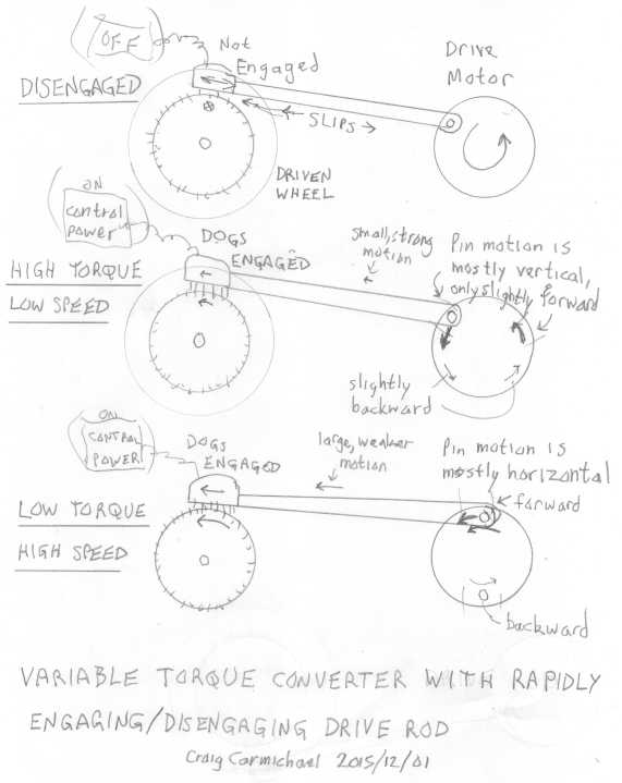 One day, out
of the blue I suddenly glimpsed a concept, an off-center pin on a motor
driving a rod. This would give a different "gear ratio" to the rod at
every point of its turning as the angle of motion changed.
One day, out
of the blue I suddenly glimpsed a concept, an off-center pin on a motor
driving a rod. This would give a different "gear ratio" to the rod at
every point of its turning as the angle of motion changed.
Moving up and down at the front and back of the circle
gives virtually no forward or back motion to the rod. Moving forward or
backward at the top or bottom of the stroke brings maximum forward or
back motion to the rod.
If the rod can be "instantly" engaged and disengaged at
the wheel being driven, to either slip by or to latch on and push, it
can capture the brief moment of any desired reduction ratio. This is
the key point. It would have to be controlled by a microcontroller with
a shaft position indicator on the drive motor. And one expects the
engaging mechanism would have to be quite robust. (Maybe a powerful
electromagnet would be work well?)
The drive motor's pin/gear would probably be considerably
smaller than the wheel 'gear' in order to scale the ratios as desired.
Eg, 1/3 the diameter could have the motor running 3000 RPM on the
highway while the wheel is turning 1000 RPM.
I'm not sure I want to try building this, but here it is
in case anyone can make use of it.
In Passing
(Miscellaneous topics, editorial comments & opinionated rants)
Energy is everywhere
The more one looks, the more one sees that energy is
abundant and is merely being kept from us by social
parasites who make a lavish living by meting energy out to us a liter
or a gallon at a time while destroying or undermining all alternatives
as they
appear. A whole national electric streetcar infrastructure that most
people loved and used daily was shut down almost a century ago by
Alfred Sloan of General Motors and his co-conspirators so they could
sell diesel buses, cars, trucks, rubber tires and (not least) petroleum
- fossil fuel. Before they started, most people didn't need those
things. In 1947 after the lengthy GM Conspiracy supreme court trial,
none of them was hanged, went to jail, or even paid a serious fine. The
message was clear: "Go ahead, plunder and ruin everything, in the name
of business and profit!"
Since around 1900, whenever anything better, cheaper,
cleaner comes along, it is shunned or sabotaged by those with power and
influence.
When Moray pulled kilowatts out of thin air from (evidently)
"lambda rays" (my name), "from beyond the gamma ray band" (Moray's
term), all
people in charge of power wanted to do was shut him down or kill him,
and his successors have been accorded similar treatment. I made
little headway with my ocean wave power proposals, now nearing a decade
ago. But we don't need to simply speak of "unproven" energy sources.
John F. Kennedy's program for a tidal estuary power project in Maine
that could have provided a major portion of Maine's and New England's
total power was shelved and swept under the carpet when he was
murdered. (A similar plant in France, built at the same time and a
quarter as large, quietly powers the Brittany peninsula.) Iceland has
pointed the path to 'free' geothermal power, but no one will adopt it
-- even dry oil exploration wells with steam hissing out of them are
hastily filled in before anyone might find out and get ideas for
connecting a turbine. Ovshinsky's large, flooded nickel-metal hydride
batteries
for electric cars that made the GM EV-1 and its cousins so good were
never allowed on the open market and production was halted, with the
company and facilities being handed over to Chevron, who proceeded to
buy up all the patents for NiMH technology they could lay their hands
on to prevent anyone else from trying to make these low cost (compared
to lithium types), long life EV batteries.
Only the first major 'free' electricity source, river
hydro dams, and things people could build in their own back yards -
wind and solar power - have gradually managed to make any sway against
the
"stingy energy" juggernaut.
While materials resource issues are perhaps inevitable, I
doubt that the energy problems of this planet are a common experience
on
other worlds. There are simply too many sources of 'free' energy that
can be harvested when people decide as a society to invest in them. And
even intermittent power such as tidal or solar can be stored one
way or another. Even with no really effective chemical battery
storage, liquid can be pumped into elevated tanks or reservoirs to turn
turbines for
periods when no other adequate power source is available.
It again all comes back to the society. What we have
lacked too much on this planet is the social will to implement larger
social projects that would bring us back a real transportation
infrastructure and as much power as we need. (Much of the world has
done a better job on electric rail transport than North America.) And,
apparently, we lack the social will to protect ourselves from social
predators of all kinds who degrade everything one way or another.
(Nasty stat just heard BTW: Financial and infrastructure crimes are bad
enough... but convicted rapists have done an average of 30
rapes before being caught. What terrible and widespread emotional,
psychic and
social
harm and havoc must they wreak?)
We must all remember that we are a part of a society of
people, and that putting ourselves first and competing at the
expense of others is inimical to the social welfare and structures,
whether or not it's done under a corporate or political facade. Is it
not social predation? Small wonder our economies are imploding and our
societies are breaking apart! When we
all consider our contribution to the welfare and
improvement of the whole as well as to our own individual welfare,
our own self awareness and our own self improvement, society will
become
sustainable -- and sustaining to each of us. But only if we protect the
contributing majority from the social predator minority - rehabilitate
those who are willing to change, and gradually
weed out any remnant from the social and genetic stream.
Small Update?: Ceres, Comet 67P & Pluto
The New Horizons spacecraft has returned some
amazing images of Pluto. I'm not going to try and interpret what we're
seeing, especially without knowing what the spectrographic data says -
and probably not even then. It's surely a deep-freeze for any potential
sort of life (let alone Earth type life). There are some very
intriguing
geological features that aren't seen on most icy worlds of our solar
system.
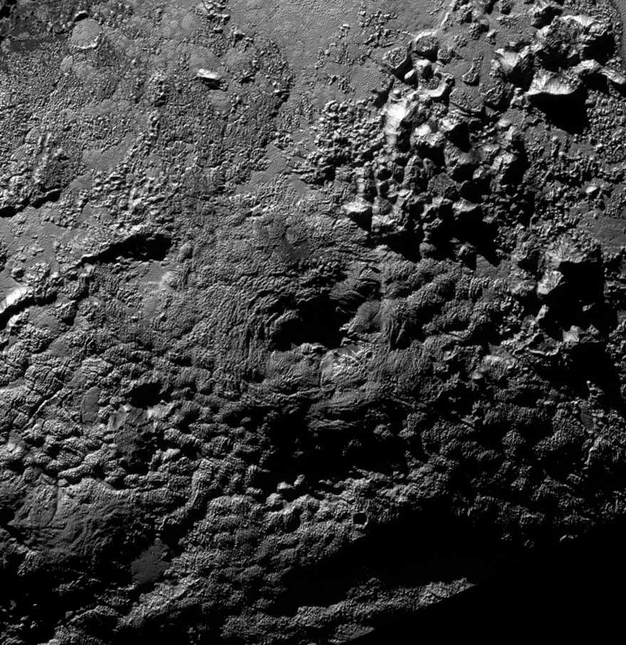 A small sample of the many unique terrain
features on Pluto.
A small sample of the many unique terrain
features on Pluto.
At Ceres, the largest asteroid this side of Jupiter,
the Dawn spacecraft has been orbiting at 1470 Km distance. The chance
of any sort of visual confirmation of the complex organic materials
being vegetation is about nil.
Ceres' surface is again described as "fluffy", as
Ganymede, Callisto and Iapetus (western hemisphere) are described, but
the writers thought it was a thin fluffy "silicate material" rather
than
organic. Other writers described organic materials. “It’s really
bland in the telescopic observations,” says Daly. “It’s like someone
took a single color of spray paint and sprayed the whole thing.”
Dawn is presently descending toward a "low altitude
mapping orbit" of 380 Km in December, where the resolution will be 35
meters per pixel - still not exactly close in. Ceres has no air -
surely they could get it down to within 30 Km of the highest terrain? -
and hence 3 meters/pixel. Why not?
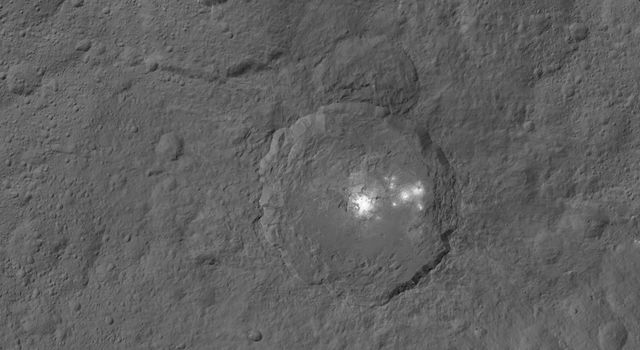 The famous bright spots in a crater on Ceres,
looking down from 1470Km.
The famous bright spots in a crater on Ceres,
looking down from 1470Km.
The crater is about 90Km diameter, so it's about 450 meters per pixel.
Perhaps the 35 m/pix lower orbit images will reveal more detail about
the dark landscape.
In all of spaceflight history so far, only the Rosetta
spacecraft with its Philae lander have made a truly close approach to
an airless world that apparently has the polycyclic aromatic
hydrocarbons in its spectral signature - and that just a little comet,
67P/Churyumov-Gerasimenko. (Unless one counts one "closest" image by
the Galileo of Callisto from about 100 Km distance and 10 meters/pixel
rez, where only the lower edge, but a very intriguing one, of the image
came through.) I've pointed out what looks like to me vegetation on 67P
(color images would doubtless be far more compelling), talk of
"prebiotic" comet chemistry is everywhere. Wickramasinghe and
Wallace have pointed out that some of the data would be very hard to
explain except in the presence of life, although they assume it must be
microorganisms under the surface.
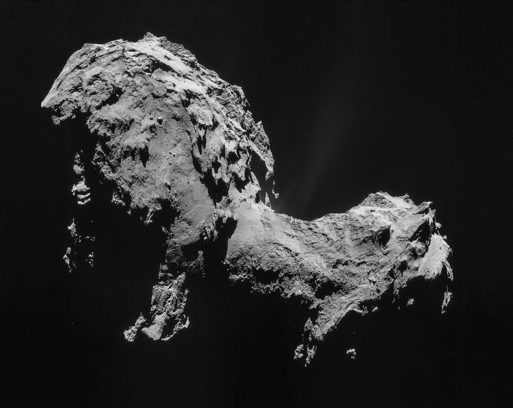 (From Wikipedia) Comet 67P from Rosetta at 29
Km distance (reduced mosaic). Length of comet is 4 or 5 Km.
(From Wikipedia) Comet 67P from Rosetta at 29
Km distance (reduced mosaic). Length of comet is 4 or 5 Km.
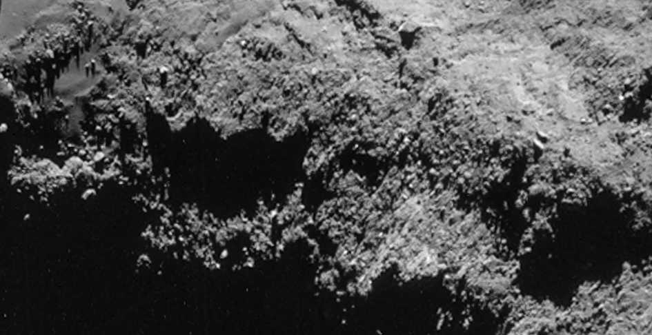 Detail from 'neck' region - apparently at about
1 m/pix. (Wow!)
Detail from 'neck' region - apparently at about
1 m/pix. (Wow!)
I was very hesitant to say any of this looks definitively like
vegetation. But the more I look,
the more I see that's suggestive of bushy, vegetative sorts of
forms, almost everywhere.
Suggestive, yes. Fluffier than it seems at first glance. Organic,
little doubt.
But bright white may be ice extrusions or ice boulders.
(Where are the color images?)
Obstruction of Democracy
"Obstruction of Justice" has long been considered a
serious offense. But there are many nefarious deeds which militate
against the
interests of society which bear no specific charge beyond the vague
"Crimes Against Humanity" or "War Crimes", and which rarely get
corrected once committed.
Now in California we have heard that officials have "lost"
something like 100000 signatures to a petition. The number remaining to
be counted is less than the number required to cause the issue to be
brought to a referendum as an "initiative" in the next state election.
This is clearly ridiculous, but one expects the issue won't be on the
ballot -- because someone with undue influence and vested financial
interest doesn't want it to be.
At the
risk of further multiplying an already absurd number of restrictive
laws, it
would seem we need one specifically for "Obstruction of Democracy". Or
maybe "Social Treason" or "Breach of Public Trust". Or all three!
Whoever ordered
this should be stripped from his position of influence and penalized,
whether it's bribed employees, some minor official or the state
governor. But one expects
the orders either came from the top or were implicitly or explicitly
approved there. Leaders should be the last people to have immunity from
prosecution. We don't put them in office to run roughshod over us, but
it happens far too often. And if those leaders are acting under
pressure from people they are beholden to for their funding, so much
the more should they be removed by judicial action over such issues.
Then the real sponsor behind it should also be found and charged. The
police should be able to apprehend anyone on good evidence that they
have committed any crime, including financial or political crimes. No
political immunity, and no having a "financial regulatory agency"
unless they can do better than the police at arresting
perpetrators instead of running cover for major financial fraud.
Such laws appear to be necessary, even vital. But they
would not be if all such people would look beyond their immediate
narrow objectives and ask themselves, "Just what is it that this will
accomplish, not only for me, but for the society I live in, which
nurtures and sustains me and has allowed me to become who and where I
am?" If they don't have a good answer, they should desist. And again we
should have mechanisms to quickly replace those who continue predation
in
defiance of common sense and common good.
Newsletters Index/Highlights: http://www.TurquoiseEnergy.com/news/index.html
Construction Manuals and information:
- Electric Hubcap Family Motors - Turquoise Motor Controllers
- Preliminary Ni-Mn, Ni-Ni Battery Making book
Products Catalog
(Will accept BITCOIN digital currency)
...all at: http://www.TurquoiseEnergy.com/
(orders: e-mail craig@saers.com)
Daily
Log
(time accounting, mainly for CRA - SR & ED assessment purposes)
Nov 1-7: covered in previous newsletter
10: Started in on studying reputedly working 'lambda ray harvester' by
Steven Mark (results duplicated by third party), Otto Ronette version
1.0. Cut PVC pipe pieces for air core coil spools.
11: Made plastic parts for "spools" for winding 3 air core coils.
12: Wound a new 'energy return' coil for unipolar motor controller
around ferrite core and tested it. It still gets hot. Wound 3 'control
coils' for lambda ray harvester. Started designing circuit board for
harvester.
13: Continued circuit board.
14-15: Ordered an energy return coil from Mouser.com to try out before
giving up on simplified unipolar motor controller, and a pile of other
electronic components. (This on-line ordering is sometimes for the
birds - If the local electronics shop had had SMT resistors I could
have pulled them out of the bins far faster.)
16: Tried BLDC4-3 Caik motor with pulsed drive on controller. (Similar
lethargic performance to ARM)
17: (house work) - Choke inductor et al arrived. Found energy converter
documentation by inventor Steven Mark.
18: Tried inductor as energy return coil - worked much better(?), ran
cool, but now diodes getting hotter instead. Reading SM documents.
19: Reading SM documents. Changed lambda ray circuit to MSP430
microcontroller control instead of simple oscillators.
20: Completed PCB layout.
21: Revisions & tidying up of layout.
22: PCB More changes: power jack, display-controller header plug for
user interface.
23: Newsletter Editing.
24: Ordered more parts for motor controller, lambda ray collector.
25: Soldered the rest of the parts on the PCB except the
microcontroller socket, which I didn't have. Got out the MSP430
software development system and tried a couple of tests.
26: (Dentist, Migraine.) µController Socket/parts arrived.
Soldered it in.
29: Re-wound control transformers for lambda converter.
Electric Hubcap Motor Systems - Electric Transport
Unipolar Motor
Controller
I wound a
ferrite energy return coil (lower), but it got as hot as
fast as the original iron powder coil. There's little need to check up
on
this detail - after running the motor for less than a minute, I can
smell the heat rising off the workbench. While the average current is
under 15 amps, it comes as short, high frequency, very high current
spikes going both directions. It would seem then that it's simply the
very high current spikes flowing through three or four feet of the #14
AWG wire of the coil that are the main cause of the heat. I could
double up the wire or use #11, but that's likely to make for only
modest improvement.
In this experimental motor controller, I was really hoping
to get rid of 1/2 the mosfets and half the diodes (and their losses),
and run only four wires to the motor, but it looked like it would take
a
huge coil with very heavy wire. That would probably cost more than all
the components saved, and it would doubtless have more losses anyway.
So it looked like it would be better to change it to the traditional
controller with high and low side mosfets and six coil power wires. It
seemed unfortunate I'd lavished so much time on this experiment.
One useful thing learned
is that most of the heat dissipated inside the mosfets comes from the
return energy passing through the body diodes, not through switching
the actual transistor itself. Thus active rectification would be an
excellent improvement to efficiency, especially for use when generating
power as an 'active generator' or when 'regenerative braking'. It'll
still be a 'unipolar' controller with reduced chance of shoot-through
currents, but the ideals are harder to attain than might appear to be
the case.
Well, maybe the core was saturating. I decided that before
giving up I'd order a really heavy coil with really heavy wire and try
it out. At Digikey they cost into the hundreds of dollars, but someone
sent me a link to Mouser, where similar inductors/chokes were only
18-30$. I picked what sounded like the best one in stock: dual
190µH @54 A max. (upper - 2 of.)
I also thought I'd see how it worked with the BLDC4-3
motor. I disconnected the ARM motor and
connected it on the 16th. Because I had changed the position sensor
plugs and then changed my mind and changed them back again, I had to
rewire it back to the
original standard. It gave the same lack-luster performance with
similar high current spikes and only reached 855 RPM, drawing an
average of 9 amps (at 15 volts from the NiMH battery) that again seemed
to
mostly go into heating the return coil. With the power supply at 25 or
30 volts the motor sounded more energetic, but with the 10 amp
limit on the supply, it was cutting in and out several times a second
and it didn't run any faster.
To get higher average current, it would appear that I need
to reduce the "off" time that ends each cycle, so the current spikes
are closer together. First, the new coil.
Production 'Choke' Inductor Coil
It arrived on the 17th. (two of it at top of image) It had
4 loops of just 3 turns
each, 2 on each side. It seemed impossible, but sure enough each loop
measured 177 microhenries (µH), just under the advertised 190.
How can that be when it took me about 35 turns of wire to reach such
inductance, on a core likewise said to be "ferrite", and even an iron
[powder] core took far more wire? This one was a smaller diameter and
just a little fatter. I guess ferrites vary more widely than I had
suspected.
Putting the two loops on one side in parallel gave the
same reading, 177. Putting them in series gave zero (canceling), or
750µH the other (additive direction). Three in series (in
additive directions) read 1596 µH and all four made 2900
µH. Wow!
The wire diameter was .10", or #10 AWG. Putting two in
parallel would make #7, and all four would be #4 - thicker than the
rest of the wiring. Well, any of those would be a lot more current
capacity than my single #14 wire coils! That seemed promising, and gave
several configuration options.
I soldered wires with lugs on them to the coil so I could
connect it to the controller, then hooked it up and tried running the
BLDC4-3 motor (it was connected). The average current seemed about the
same, but this coil hardly got warm. Instead, the energy return/flyback
diodes got hotter, much faster. Come to think of it, that probably
wasn't enough inductance. The motor coils were as I recalled 90µH
and the first energy return coil was 400µH, not 200 as I had
somehow been thinking. Using the whole coil provided 740µH with
#7 equivalent wire. That didn't seem to change things. The diodes still
got very hot. But the coil was only slightly warm.
I started thinking that it was as if the coil was a short
circuit, and the diodes were just shorting across the motor coils.
Perhaps the 200-400 amp current spikes, far over the 53 amp rating of
the choke, saturated the ferrite core and resulted in a low inductance
just at the critical moments? On the 24th I ordered some more 'choke'
coils - another the same, and three of the next lower rating (and 19$
instead of 25$).
On December 1st I soldered wires to the second one like
the old
one, and connected it in parallel to the first. The first one was
750µH, the second one was about 800, and together in parallel
they were about 400. Rather than the current dropping or the RPM
increasing, the current stayed similar and the motor RPM dropped. The
diodes seemed to get just as hot. Not what I was expecting!
I wanted to look at oscilloscope traces
I'd done earlier and looked at TE News #89. In there I mentioned
bypassing the coil and checking the effects. Why had I not thought of
doing that with the new coils? I bypassed them and the operation wasn't
notably different. Perhaps I was doing better with my first, homemade
coil? What could be so different between coils of similar inductance?
I'll have to try a few more things next and see what's
really happening. What might happen if I increased the filter
capacitance to hold the supply voltage more steady as current spikes
came and went? And how about some filter capacitors on the motor side
of the coil?
But as I think about it, the diodes are carrying all the
return current, equally whether it's going back to the supply or just
shorting the motor coil. The return coil is no longer heating up, so
it's no longer dissipating a bunch of the energy. So actually it makes
sense that they would get just as hot either way. So, I should get in
and see the exact voltage waveforms with the oscilloscope to see
exactly what's going on.
Active Rectification
I had purchased some "active rectifier driver" chips with
my order at mouser. With the coil cool and the diodes hot, it appeared
it might
be
time to make the circuit. I'm not sure the component count will be less
than the "discretes" circuit I designed, but perhaps it'll work better.
(?) Anyway I didn't get to it by month's end. Then...
Microcontroller Version?
As I put together the lambda ray converter controller, it
occurred to me... it had a microcontroller that could be programmed for
anything, and three coil drivers. If I wanted it to be, with only minor
changes it could be a microcontroller controlled unipolar motor
controller! I would want to double up the mosfets for higher power and
of course change them to low voltage, high current types, put in level
shifting to 12 volts for the mosfet gates, gate resistors to slow the
switching and add a couple more user inputs (fwd-rev, electron pedal),
but all the rest including the pulse drive and the active rectification
could be done by correct programming of the micro.
It would lack a few hardware safety features of real motor
controller chip such as
undervoltage lockout and turn-on delay to prevent shoot-through... but
how vital are those really? Just one monitor on the supply voltage can
tell if the supply to the transistors is too low for proper switching,
and if a floating supply to an active rectifier circuit is low, one
simply
loses some or all of the 'active' in the rectification. Turn-on delay
can be programmed, and in the unipolar controller the three phases are
separate - the only thing to be sure is that the active rectification
is off when the coil drive is on. Hmm, that's guaranteed if I use
IRS2003 half-bridges with a .5 µSecond dead zone. (.8 µSec
would be better.)
In fact, features of the low-frequency pulse width
modulation and the current limit modulation would be much easier to
implement and
control in software. All provided that the micro can respond fast
enough to the current ramp-up to shut the coil off in good time, before
mosfets start blowing. That's always been my main hesitation with this
type of control. Maybe I could add a comparitor or opamp to do that one
job in hardware.
Realistically, with the hardware safety provisos, this is
probably superior. If I really get into the micro programming, which
should be very doable, I may well give it a try!
Variable Crank Rod "Gear"
(Another possible type of torque converter FWIW)
One day I suddenly glimpsed in my mind a way to make a
variable
drive gear
with an off center drive rod having a ratchet gear with controllable
ratchets/cogs/dogs. It could certainly be used to drive a
vehicle using a
smaller motor. Whether it might be actually practical I'm somewhat
dubious, but
I'll describe it in case someone thinks it would be good for
something or might get another idea from it, or might think of a better
way of implementing the function. Or maybe I'll
come up with a better implementation than solenoid activated dogs
myself? (Strong electromagnet?) Anyway, here's a diagram to help
clarify the idea.
The key is ratchets/cogs/dogs that only engage the driven
wheel at certain specific points of
rotation of the drive motor, which points are dependent on the desired
"gear ratio"
and direction of motion. I would think a microcontroller and
fast electrical activation of a magnetic or electromagnetic
ratcheting/dogging
system, with a good motor rotor position sensor, would be the most
practical. When this is disengaged, the wheel and motor aren't
connected and the drive arm just slips freely back and forth at the
wheel. [top diagram]
As the crank on the motor turns through the vertical
(crank pin at the front or back), the motor end of the rod goes up or
down, but the wheel end doesn't move back and forth. As the motor turns
through the horizontal (top, bottom), the rod goes back or forth at the
speed the motor is pushing - 1 to 1 or maximum ratio. [bottom diagram]
Just before and just after the motor crank has passed the
vertical motion position (front, back), the rod moves only slightly
back or forth. If the cogs are engaged at this point, the motor has
great leverage and a high "gear ratio" can be attained. [center
diagram] At the 45°
points, the ratio is sine of 45°,
or 1 to 1.414.
If the wheel's gear/sprocket/pulley is larger or smaller
than the cranking radius of
the pin on the motor, these inherent gear ratios can be scaled by some
desired factor. On a vehicle, generally the motor would run faster than
the wheel even on the highway, so the motor pulley/pin would be smaller
diameter than the wheel 'gear', perhaps by 2 to 4 times. (This would
reduce angle oscillation of the rod at the wheel, too.) Presumably the
driven wheel would have sufficient
inertia (eg, the mass of a car) that the motion would carry smoothly
through the undriven periods, which are longer than the driven times.
I don't know what made me suddenly think of this, so
unrelated to anything I'm doing at the moment and so different from
anything else I've tried, and I do quickly note
some drawbacks with such a system. It would seem that the ratcheting
mechanism and its control wiring must be flying back and forth with
the drive rod. (Well... I've thought of another possibility...) And I
don't know just what ratcheting/dogging mechanism
one would use
to latch and unlatch the drive rod from the wheel. And I note that
without a counterbalance the motor rotor's weight would be unbalanced -
not to mention the unbalanced drive force on the motor. And the wheel
can only be
driven for short segments of each rotation of the motor. But perhaps it
has potential. Here it is in case it's worth something!
Electricity Generation
Lambda Ray Energy Converter
Atmospheric ion charge energy sounded very promising to
me. It's
a known energy, and people have used it to charge cell phones and to
run motors. And perhaps it can be harvested in useful amounts. The Ion
Energy Group could get over a kilowatt, but only on a turbulent day.
Microtextured graphene streamers on the antenna wires magnified their
energy collection tenfold, and perhaps there may be further interesting
developments to come. If they could magnify it by ten again it would
perhaps be useful, but to get what they had required a huge, very tall
antenna array.
Originally it seems Dr. T.H. Moray believed he was using
atmospheric ions to generate kilowatts via resonant circuits and his
special mineral germanium diodes - that seemed exciting. But this idea
was evidently wrong, as
I discovered in further reading. It was said his later units would
work in interior spaces without an elevated antenna connection. An
internal copper plate sufficed. The only external connection that
seemed vital was a good ground. As
far as I can tell, that means the devices must actually have been
harvesting
lambda rays - the ultra-high energy, ultra short wavelength
electromagnetic ray band perhaps hundreds even to hundreds of thousands
of
times higher frequency than gamma rays.
Moray eventually came to this very conclusion, in the
1920s,
but the confusion about this source of energy persists. It didn't help
that there were no detectors capable of sensing it. It
appears the rays at up to 10^27 Hz were only specifically
detected and identified about
2007. Like early man having no scientific understanding of what fire
is, but making and using it nonetheless, these ultra ultra short rays
have
been converted to usable electricity by a number of people. Some
identified
it correctly if not very specifically as "radiant energy".
Various people have tried
to understand the energy source as: zero-point radiation, radiant
energy, cosmic energy, cold electricity, the sea of energy, dirac sea,
vacuum fluctuations, higher dimensional energy, zero point vibration,
residual energy, quantum oscillations, vacuum electromagnetic field,
virtual particle flux, dark energy, aether, negative electricity,
bioenergy, orgone, space field energy, hyperspatial energy, life
energy, creative vibration, tachyon energy [say, weren't tachyons
invented by Star Trek TV show?], prana, chi, scalar energy, neutrinos,
and quantum flux. (Source: Break Through Power - How quantum-leap
new energy inventions can transform our world, by Jeane Manning
& Joel Garbon)
Moray
eventually hit it working from theories by Dr. Gustav Le Bon, a Belgian
physicist. His conclusions (like Le Bon's) seem to have been ignored,
perhaps because the actual rays remained so long unidentified... and
perhaps because of the way he presented them:
"The
study was completely revolutionary. Dr. Moray advanced the Le Bon
theory to the point where it became a plausible thesis. He was
convinced now that a "radiant sea of energy" suffused the earth. Moray
repeatedly stated that this "sea of energy" continually permeated the
earth in energetic gusts. The rays he proposed were responsible
were
"from beyond the gamma ray bands". Recognizing that these naturally
prolific energies and their strange dynamics required a special
interceptor, Dr. Moray stated that:
"The most widespread and mightiest of the natural forces has remained
so long unrecognized ... because man lacked the reagents necessary for
the proof of its existence"."
Here the mystical sounding "Sea of Energy" concept seems
to overshadow the more important concept: the nature
of the radiation (my bold above) - to the point where I missed
it - glossed over it - on the first couple of readings. Moray wrote a
book called The Sea of Energy. Perhaps a title something more
like "Spectral Energy Beyond Gamma Rays" would have been more
immediately informative and piqued scientific curiosity to the point
where it was studied and became mainstream? (Anyway, I haven't read the
book... because of the title?)
All of which brings me back to the experiments I did in
this direction two years ago. In TE News #68 I incorrectly identified
the cosmic microwave background radiation (CMB or CMBR) as the apparent
source
of the radiant energy. I was then corrected by a nuclear physicist (or
at least someone obviously with abundant knowledge in that field) who
pointed out there really wouldn't be significant energy there. By TE
News #69
(Nov. 2013) I had found that radiation of around 10000 times shorter
wavelength/higher frequency/higher energy than the highest energy gamma
rays had recently
been discovered (in 2007) by an "X-ray observatory" spacecraft. This
was what I was looking for. With
ten trillion electron volts per photon and a sky lit (tho unevenly) in
all
directions
by gamma rays and presumably also by this far higher energy radiation,
it became apparent that this must be the source of the "free energy"
that a few had managed to get kilowatts from. All with higher voltage,
fast switching, oscillating circuits... which category Moray's devices
seem to
fit into.
With some unique germanium mineral diodes, special
vacuum tubes designed by Moray, and no reliable schematic diagrams or
complete
description, Moray's designs seem vague, far off, unreachable. And it
would
seem they are a moving target, since later versions were different than
earlier ones.
But others appear to have succeeded since Moray's time.
An intriguing circuit is Otto Sabljaric's 2009 "TPU-ECM" (Toroidal
Power Unit - Energy Conversion Machine"). For this a schematic and
considerable written information - 55 pages - is available. Kudos to
the authors for detailing their experimental development thoroughly
for others to follow! In addition, a third party on youtube claimed to
have duplicated the experiment and attained similar good results. This
design itself was evidently based on information by the
original "TPU" developer, Steven Mark, and on Floyd Sweet's
"Diamagnetic Torsion Oscillator" ("DTO").
In TE News #70 & #71 I did some experimenting with
oscillating circuits. But somehow rather than copy Sabljaric's
experimental but evidently successful copy of the Mark design, I tried
my own variant, partly because it was easier to make and partly because
using an iron powder coil core instead of air cores seemed somehow
"more industrial" or something. And maybe I was copying the Brazilian
inventors who had just created small and large energy converter units
to sell. (which they called "Earth electron receivers", again in
ignorance of the energy source.) Perhaps I just didn't like the
amateurish setup with wires taped to plastic tubes to form the rings.
But iron [powder] cores aren't good for high frequencies, and I later
thought I should have used ferrite cores. The air cores of the Ronette
design are of course also good for high frequencies. About the same
time I became more
fascinated with magnet motors and after burning out the power
transistor in the lambda ray experiment device (probably because of the
higher inductance iron core coil), I stopped working on it. I was no
more successful with the magnet motors.
This time I resolved to start by humbly copying the
"Otto Ronette TPU" design and (hopefully) getting it to work before
trying any
original expedients. [If his name is Otto Sabljaric, I don't know how
the name or word "Ronette" fits in.] If it worked okay I might just try
making it easily
replicable and more robust, for example by making circuit boards,
connectors, metal cases (deep pie dishes? - Lambda rays seem to go
right through anything.), and perhaps ceramic parts
to wrap the collector wires around and hold all the coils in place. And
then maybe rectifying the radio frequency output (from descriptions
that's what Moray was getting) to DC and downstepping it to 12(?) volts
for tying into a power inverter or other conditioner
for running regular appliances. That would be a key to actually making
it useful and practical.
On the 10th I started going over all the documentation in
the PDF document, which is available at a number of places on the web:
Filename: otto_ronette_TPU_ECD-V1_0.pdf
Reference: SM TPU
Version: 1.0
Date: 6/9/2007
Number of pages: 55
Document: ECD Energy Conversion Device
state: Approved
TPU ≡ ECD
INVENTED BY STEVEN MARK
Energy Conversion Device
D I S C L O S U R E
By Otto and Roberto
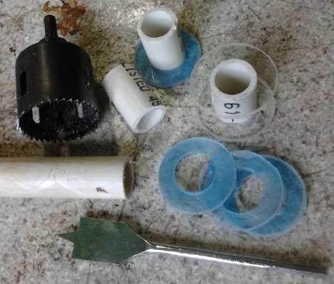 I cut 3 short
pieces of slightly over 1" O.D. PVC pipe to
wrap the
control coils around. Then I cut 'lexan' ends to glue onto those with a
~2" hole saw, and then drilled a 1" hole in the center of each with a
flat blade wood drill. I filed out the holes until the ends fit snugly
on the pipes. I 'glued' the spools together with methylene chloride
solvent, which liquifies both types of plastic and then evaporates. (I
suppose the
spools could have been made by 3D printer from ABS just as well.) The
winding length between the ends is about 1.25". The directions say
"about an inch" but
without saying whether that's diameter, length or both.
I cut 3 short
pieces of slightly over 1" O.D. PVC pipe to
wrap the
control coils around. Then I cut 'lexan' ends to glue onto those with a
~2" hole saw, and then drilled a 1" hole in the center of each with a
flat blade wood drill. I filed out the holes until the ends fit snugly
on the pipes. I 'glued' the spools together with methylene chloride
solvent, which liquifies both types of plastic and then evaporates. (I
suppose the
spools could have been made by 3D printer from ABS just as well.) The
winding length between the ends is about 1.25". The directions say
"about an inch" but
without saying whether that's diameter, length or both.
The wire sizes were given in millimeters. They seemed
pretty
thin, equivalent to #24 (3.2m of it) and #27 AWG (10.5m). I had a lot
of magnet wire
in my boxes, but the smallest was just one small coil of #22, followed
by plenty of #19 or #20. I went to buy some thinner wire for the
long coils of "#27", but I forgot it was rememberance day - the motor
shop was closed. The next day I got some #28 and #30, donated by Jim
Harrington at AGO. I used #22 and #28.
Daring fate (making a
slight
change), I wound the wires
separately, the secondary
on top of the primary. That way (I thought) the far end of the
secondary would be physically separated from the primary voltages. With
thin magnet wire insulation, adjacent wires with drastically different
voltages can arc across. It turned out there wasn't enough wire to so
separate them. Some of the thin secondary wire went into the gaps
between primary wires. Later I rewound the secondaries over a layer of
paper tape to separate them from the primaries, and gradually from one
end of the spool to the other, to separate the low and high voltage
ends of the secondary. (I don't want arcs across thin magnet wire
insulation!)
 I
got about 48 turns of #22 primary wire, which didn't
quite fill one layer.
I
got about 48 turns of #22 primary wire, which didn't
quite fill one layer.
I noticed the Floyd Sweet coils had far more turns in the
secondaries (2000), and this made sense to me as lambda ray conversion
seemed
to be favored by switching higher voltages. Since the initial switching
might be 9 or 12 volts from a small battery, and perhaps instead 900 or
1200 volts might be desirable on the secondary and on the collector
coil, for a 48 turn primary one would use 4800 turns of #28 wire. The
10.5m length of wire specified only made 126 turns. Winding far more
turns would be departing
rather widely from the instructions. But I decided to stick to the
instructions, and maybe try that later. When I rewound over the paper
"removable label tape" it came to just 117 turns... oh ya, slightly
larger diameter!
My coils looked much finer and neater than the photos of
the originals, where I'm suspicious that they used much thicker magnet
wire than they said.
Later, having got a commercial 'choke' coil for the motor
controller that seemed much better than the ones I had made myself, I
started thinking - maybe I could just buy the coils/transformers I
wanted. What might be available? But I didn't check into it at on-line
electronics suppliers. They aren't that hard to make.
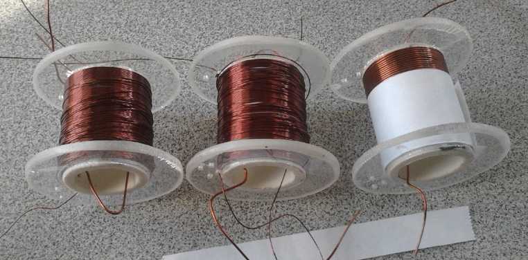 Air core control transformers, showing the
secondaries (left, mid)
Air core control transformers, showing the
secondaries (left, mid)
as later redone with paper tape (right) to separate them from the
primaries,
and wound from one end to the other to separate different voltage
region wires.
I still had the little
'collector' wire rings assembly from 2013
and I added the new control coils to that.
The next component was the
circuit board, and I started in on the design. It needed three
oscillators to generate up to three independent frequencies, and three
ultra-fast coil drivers able to put good square waves into the coils. I
wanted to put them all onto one circuit board.
Again from the sounds of it, the device outputs its energy
(or some of it)
as high frequency or radio frequency pulses (because the input pulses
have strong harmonics?), which I'd like to convert to
'normal' and 'predictable' DC. Maybe I'm just uncomfortable with light
bulbs lighting up without the filaments lighting, just by putting them
near the antenna. I've seen it myself at radio transmitter sites with
both fluorescent and incandescent bulbs (Thank you Maynard Atkinson
& Comox Airport outer marker beacon, 1975!), but it still seems
weird. And
of course there's the potential for getting radiation burns. I'd rather
the high frequency stuff stayed inside a box. But conversion to DC is
an "add-on"
rather than part of the lambda ray conversion itself.
Change of Control Circuit
Otto & Roberto gave credit at the top of their work to a Steven
Mark, cited as the original inventor of the "TPU" toroidal power unit.
On the 17th I noticed, fortuitously, that I had downloaded in 2013 a
PDF document with his name in the filename, which I had never looked
at. Now on the 17th, 18th and 19th I read what turned out to be an
enlightening and educational
compilation
of e-mails mostly from Mark. There was a lot of excellent theory about
the
principles and practice of getting the elusive lambda rays to release
their energy in a controlled manner. Including THE theory of how it
works in the first place. I have written about this excellent if not
vital document
in a separate section below.
That key point I hadn't known is that every
time a
DC voltage is switched on, there's a bit of lambda ray energy
conversion in the wire. It's
that simple! People in certain
circles have long noted
the extra "DC
kick", especially of course with higher voltages and long power lines,
and wondered what
causes it. The trick then - as I've
noted before without having the exact reason - is to have these
conversions
build on themselves with resonant oscillations of high-speed on-off
switching. A DC kick on top of a kick on top of a kick becomes a high
voltage containing some serious energy.
Really, it all started to sound pretty straightforward. At
least in theory.
Naturally the document modified my ideas of how to go
about the project. I started to feel it was all essentially
understandable,
I wasn't just copying something whose workings, for all that I grasped
important parts of them, were still somewhat mysterious.
Especially the system controlling the pulsing seemed to be a key, if
not the key feature. I noted that if the pulses were simply
generated as I
had planned by unco-ordinated frequencies, especially if the energy
levels "surged" as Moray believed, there would probably be the
occasional "rogue wave" with the collector hitting an outrageous
voltage that would probably destroy everything, similar to Otto's
disaster or even the TV set explosion (see Mark Letters, below)...
probably just
about when I thought it was coming along really well.
So I started thinking about using a
microcontroller to generate the pulses and to monitor everything.
Especially the collector/output coil voltage. And this could have an
advantage of being
programmed to automatically run through a whole pile of sets of
frequencies looking for the best ones. In fact, all kinds of control
strategies can be tried "simply" by changing the firmware. Not simple
in this, however, is figuring out control strategies that might work
well. and then fine-tuning them. But the idea quickly grew on me.
On the 19th and 20th I replaced the three 555 timer
oscillators with an MSP430G2553 microcontroller, and (roughly)
completed the circuit board layout, driving the same mosfet coil
drivers as used by Otto. Mark said the driver board had to be in the
center of the toroid, that some circuit board materials interfered with
operation, and that it worked best with the components raised 1/2" off
the circuit board. That's hard to do with surface mount and socketed
components - but the trace lengths can certainly be kept very short.
With high power coming through with the switching, the issues are
probably electrical noise issues pretty similar to those in high
powered motor controllers.
Personally, I'm not convinced the collector loop even needs to be a
toroid - surely an ellipse or oval should work about the same? Or (3
control coils) a triangle? But perhaps equalizing the drive wire
lengths to the coils (as well as the collector loop lengths between
coils) is desirable. The control could be centered but well above or
below the coils.
 I
connected the 3 unused pins of the power and control
header connector to 3 port pins on the MSP430, thinking to connect up
to 3 pushbuttons or status LED.s. On the morning of the 22nd I
remembered my 1987 "Display-Controllers" with a 4 digit 7-segment LED
display and 6 pushbuttons, connected via a 4-wire serial interface to
any microcontroller. I still had a couple, and furthermore, in 2013 I
had programmed the MSP430 to display all the ASCII characters (as well
as
7-segment displays can) as a test of the MSP430 programming system I
had set up.
That will give many options for display and user control. Finally I
connected an "extra" analog input to the 4-pin header that's to run to
the circuits to measure output voltage and temperature, just in case
any other reading was needed, or for use as a user analog control
input. (And the 20 pin microcontroller still has some unused
I/O pins!)
I
connected the 3 unused pins of the power and control
header connector to 3 port pins on the MSP430, thinking to connect up
to 3 pushbuttons or status LED.s. On the morning of the 22nd I
remembered my 1987 "Display-Controllers" with a 4 digit 7-segment LED
display and 6 pushbuttons, connected via a 4-wire serial interface to
any microcontroller. I still had a couple, and furthermore, in 2013 I
had programmed the MSP430 to display all the ASCII characters (as well
as
7-segment displays can) as a test of the MSP430 programming system I
had set up.
That will give many options for display and user control. Finally I
connected an "extra" analog input to the 4-pin header that's to run to
the circuits to measure output voltage and temperature, just in case
any other reading was needed, or for use as a user analog control
input. (And the 20 pin microcontroller still has some unused
I/O pins!)
Then I thought that it
would be nice to have a socket for
a power adapter. There are ways to have the control unit power itself
and Mark
eventually added one just so he could say there weren't any batteries,
but using a battery or power adapter is simpler. (People would insist
that a kilowatt of power to run lights and toasters for hours must
somehow be coming from the 1 watt-hour battery in the converter,
however ridiculous that
is. At the moment I don't care.)
If the power had a separate connector, the original pin
header connector
for power only needed
to connect up the display-controller, with 6 pins (4 I/O pins, +5V,
Ground). And I kept seeing
little ways to shorten traces or otherwise improve the layout. In
between playing (violin) in an afternoon orchestra concert and
everything else,
I revised the board by evening. It still needed the same 2 jumper wires
for a single sided board. So for external connections it had: 3 pairs
of pads to solder the control coil wires to; a 6 pin header connector
for the display-controller (or other user inputs/displays); a 4 pin
header connector for the voltage of the collector coil and temperature
of the wiring; a power adapter socket. It might or might not need small
heatsinks on the power mosfets and the voltage regulator. It was
starting to at least look like a real product.
On the 24th I printed the artwork, etched the board,
drilled the holes, and put on some of the parts. I discovered that if I
had any 20 pin DIP IC sockets for the microcontroller (I probably did),
I had no idea where they were. (Last year I had to clean out the
storage room where they had been for ages.) And I only had a few
of the coil driving mosfets. If this got serious I might need to come
up with more units. So I spent another evening ordering electronic
parts. The next day I put the rest of the components on the board, less
the missing socket, which should arrive in a day or two.
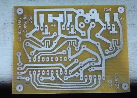
Shots of the board - Etched (tinned with "liquid tin")
As usual for better reliability on single sided PCB and perhaps lower
quality results,
I made wide traces, and I expanded small pads on the final image
in "Graphic Converter".
(To my amazement the board etched in 4 minutes.)
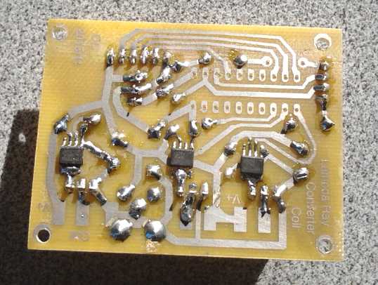
Bottom view showing high-speed complimentary mosfet gate drivers.
(without µController chip socket, & one resistor TBD)
Top view.
On the 29th I rewound the secondaries of the control
coils. I didn't like having the secondary and primary windings
touching, and I didn't like having wound the secondaries back and forth
on the spool, which puts one end by the other end, with the thin magnet
wire insulation.
After removing the first secondary windings, I found some
"removable label tape", and wound some on to cover the primaries and
make a space between it and the secondaries. The paper seemed about the
right thickness and won't melt down if it gets too warm. Then I wound
the secondaries back on, this time going gradually from the right edge
and ending at the left edge, so turns near each other are also near in
voltage and the (most voltage difference) ends are farthest apart.
This may be being overcautious. OTOH it's one less thing
that might go wrong.
2 spools with rewound secondaries, 1 with 1/2
the separator tape applied.
The spools on the lamp cord collector coils. The resonant frequencies
are
affected by the collector wire lengths, so having the microcontroller
scan through
frequencies to find the right ones will avoid manual fine-tuning of
individual units.
Design Issue (goof)
After making the circuit board, I belatedly started
getting
concerned about having eliminated the open collector transistor drivers
for the gate drive dual mosfet pairs, IRF7307.s, in the circuit I used
from
2013. What was I thinking? Oh yes... with the 555 oscillators
everything was going to run at 12 volts; all compatible. When I changed
to the microcontroller (they're all 5 volts or less) the pre-driver
level shifters again became useful if not vital.
If everything runs at 5 volts, all's well, but if driving
a 10
volt powered complimentary pair with 5 volts, both mosfets will be on.
On the other
hand, does driving the gate with just 5 volts fully turn on the IRF840
coil drivers? With 12 volts there was definitely no issue. Looking at
the specs, it would appear my best choice -
besides not having taken out the open collector pre-drivers - might be
to run at about 6 volts. -1 volt isn't quite enough to turn the P
channel fet of the pair on. I could still power the coils with 12 volts
or any
other level (eg, 24 or 48 volts for more DC kick) if 6 isn't enough.
But in trying to simplify, I've
needlessly complicated things. The 78L05 voltage regulator will
probably have to be removed and replaced with 2 diodes to drop 1.2
volts.
Well, until I try it I can hope 5 volts (regulated) will
be enough, tho the
graphs show the IRF840's gate as being driven better with 6 volts or
more.
With 5, the voltage regulator is replaced with a wire. Being simplest
(since I have a 5 volt regulated power adapter), that's what I'll try
first.
However, in the course of my reading I found I could have
replaced the 3
transistors and 6 resistors I would have used for level shifting with 1
SN7407 or SN74LS07
and 3 resistors. Unless 5 volts works great, that'll be the thing to do
for version two.
(But I haven't even tried version 1 yet - Ahrg!)
Later it occurred to me I might use (eg) 12/5 times as
much wire on the transformer secondaries to give the effect of 12 volts
from a 5 volt pulse on the primary. That just might allow 5 volt
operation and solve everything.
Another good change would be to separate the two closely
spaced power mosfets more, especially if heatsinks prove to be
necessary. (If not, it's probably not a concern.)
Control Circuit PCB Files
Here are the "version 1" control circuit and the board
layout EAGLE files: circuit schematic
- PC board - image of board.PNG Please realize that
nothing has been tested yet, nor has the microcontroller been
programmed.
Programming Strategy
Then what? Ah, programming the microcontroller, of course!
I got out the software development bits and assembled and ran a couple
of test progams. Thank goodness I put in the terminal and the debugger
command line instructions as comments in the source code files! I would
never have remembered what to do! I noted that my circuit board,
after all its little size changes during development, happened to be
exactly the same size and
shape as the MSP430 development board.
There's probably some way to make it so I could download
new software straight to the lambda board, but I'll stick with doing it
in the SDK board and then moving the MSP chip to the lambda board, to
avoid having to learn something new at least for now.
As to a control strategy, I think the first thing to try
will be to have one oscillator sweep the spectrum from say 45 Hz to 10
KHz or higher, and find frequencies that seem to resonate, where the
kicks attain a higher voltage potential. I'll keep the pulse width
short, whatever the frequency, to minimize power to the coils. (Pulse
width... one more variable to contend with!) They
need the voltage switched, not held on for long once switched. (As each
resonance is hit, it
should display the frequency and the voltage for the experimenter.)
Then the best 3 of those frequencies (or according to Mark somewhere a
little off from them to prevent getting too much!) can be the ones the
3 oscillators are set to for energy harvesting. (If there's a peak at
60 Hz, I'll suspect it's trying to harvest from nearby power lines!)
It may be that the best frequencies will vary with
the load connected, since that's really part of the whole circuit. At
least one experimenter found his circuit only worked with the load, a
light bulb, attached. And
when each collector unit is made, especially by hand, there may be
small differences in lengths of wires and other construction details.
An automatic scan, and perhaps other automatically determined
parameters or choosing settings from a list, should take all the work
out of determining and adjusting to the best frequencies and operating
conditions. This is another reason the microcontroller control will
probably prove much superior control to any hard-wired circuits. Maybe
it can even control the ouptut so well that further voltage regulation
will
prove unnecessary, depending on what's being powered. If an electric
heater or light bulb (biggest electrical loads) gets an average of 120
volts, it doesn't matter so much whether it's AC or DC or components of
each, or what the AC frequency(s) is.
I think I'll have 3 "time-on" variables and 3 "time-off"
set by the determined frequencies and pulse widths, and 3 "current
count" variables, which will each count down per time period until it
hits zero. Then the time-off or time-on variable to count down from
will be loaded and the coil drive signal will be set off or on,
depending where it was before. The "quantum" time period will be set by
timer A interrupt and the variables (and *probably* the drives port
pins) will be modified in the interrupt handler.
Hmm... on the other hand, other pins of the same port goes
to the user interface. It might get tricky to test and modify the same
port both in an interrupt and out of one. Perhaps I should have used
one port only for the coil drives, and different ports for everything
else. Or am I fretting about nothing? Time to check the MSP430
instruction set and see what can be done and what's necessary! Ah,
individual [port] bits can be set or cleared in a single (and hence
uninterruptable) instruction - problem solved!
Steven Mark Letters Compilation: the theory and secrets of
harnessing lambda
ray energy
The paper by Otto & Roberto mentioned that the "toroidal
power unit" (TPU) was first
developed by Steven Mark ("Mark" or "SM"). I searched for this name and
found something quite disturbing, saying his device was real but that
he was a fake, just in it for attention, that he would never tell
anyone how it worked, and he probably hadn't invented it. In the clips
of text of many search results he's described as a "tinkerer" of "small
intellect" and a "hustler". From the sheer number of such results,
anyone would get the impression that he left a trail of angry and
disappointed people behind him wherever he went. That certainly didn't
sound like the character of a brilliant inventor. But apparently the
device
worked. No one tried to dispute that. If he hadn't invented it, who had?
That all seemed
discouraging, but a couple of days later I noticed that in 2013,
somewhere I had found and downloaded a ".pdf" file that had his name in
its filename.
(Steven_Mark_TPU_compilation.pdf)
This proved to be a lengthy compilation
of e-mailed letters on the energy converter subject from Mark to a
correspondent named
Lindsay. Lindsay's side of the
correspondence isn't included, but it would probably be superfluous.
Mark said much in letters near the beginning about the
suppression of the
technology and about extensive efforts to defame his character and
motives - just such as what I had so recently read. According to Mark
these were outright lies by people who he'd
never even met, claiming he had "broken agreements" and "pilfered
investments" with many people. The writers wouldn't respond when he
wrote to them. Okay, one soon got the impression that one or more
people was being paid to spread defamatory lies to attempt to discredit
Mark's work. But was this whole document then just another, very
lengthy,
exposé about social predators killing free energy?
But no! Reading on, over the course of many letters, he
covered many technical
details... including the essential theory behind it all! In reading his
letters,
one gets a very different sense, of a man who is sincere and passionate
about improving the world, an electrical engineer and very
knowledgeable about electronics including old tube stuff we barely
covered in my BCIT classes in 1973-75.
There was a lot of information, and I started to see that Otto and
Roberto for all their good work were inexperienced amateurs by
comparison. Well, they never claimed otherwise, and they did pay
tribute to Steven Mark in their introduction and name him as the
inventor... or I wouldn't have sought him out!
* Mark gave the very basic point of where to start, which he
repeated as people on some web site discussion which he read but didn't
seem to post on himself (at overunity.com, perhaps?) seemed to have
missed the point:
"The
very
FIRST
example
I
gave
you was that; It is common scientific knowledge that if you have a
piece of wire and first run electricity through it you will have a
small kick when first energized. The kick is universally attributed to
the earth's magnetic field. ["attributed to?"...
How would that happen? It
sounds like a wild guess for lack of a
satisfactory explanation.]
OK the point is; YOU CAN GET SOME
ENERGY OUT OF THE EARTH!
Next
point; YOU CAN DO SOMETHING
VERY SIMPLE WITH A WIRE TO SHOW THIS.
Next
point; YOU CAN SEE THAT YOU
CAN GET MORE OUT OF A PIECE OF WIRE THEN YOU PUT IN TO IT. [THAN! the word is THAN! -- the grammar police]
WE are not talking about a coil or
a transformer or anything developing a primary to secondary flux.
We are just talking about a straight
piece of wire, some electrons and a method of measuring what comes out
of it.
I even gave you some easy to obtain
references to this phenomenon in a few technical journals."
This was Mark's starting
point. I don't recall being taught about this in electronics
classes. I guess it's just not an issue with low voltage, low power
solid state circuits. Unfortunately his method of measuring the "kick",
and the references, weren't in the document, and I was unable to find
anything on the subject on the web. However "kick" is probably
not a term that would have been used in scientific/technical papers,
and naturally that common word also returned mostly completely
unrelated
results. But
Otto measured and printed tables of the relative "kick" of different
lengths of wire made of different metals in his paper, in attempting to
determine the best one and what length of it to use. His measurement
technique was only partly explained, and that so casually that he must
have
assumed the typical reader would already know all about the "kick"
effect. Perhaps he had access to Mark's method?
And evidently nobody suggested the kick was a
tiny blip of potentially free energy until Mark came along. He had an
extra reason for thinking there must be powerful energy available from somewhere:
years
before
he
had
heard
about
an
"exploding"
GE
color
TV
that
had
incredible magnetic effects like pulling nails right out of the walls,
attracting them to itself. And this one particular earlier model of TV
(which would
doubtless have been all vacuum tubes), exploded in this spectacular
manner more than once. Where could such energy have come from, and
could it be captured in a more productive manner? Wherever it came
from, the turn-on "kick" was energy that, like the TV, hadn't
been put in from the power supply. He then spent [at least] 15 years
developing his "TPU" to harness that energy.
I assume that just as the voltage is turned on, there
is a small conversion of lambda rays in that instant: their energy
appears to be released by any sudden change in electric field, and
applying a voltage to a wire with a switch is such a change. I thought
it was hard to attain this conversion, but it seems it happens all the
time! - in a small way. It's that simple! (I also surmise from the
Le Bon info that lambda rays are probably also what causes some
elements to
be radioactive under typical Earth conditions. They actually don't fly
apart all
by themselves for no reason, but because they've been struck by an
energetic photon that creates too many electrons for the atom's
electron field or otherwise disrupts it. But that's a whole other area
of study.)
Still looking for info and better verification about the "kick", I
finally registered on
overunity.com on the night of the 21st. I found much discussion
about it there but not much was definite. But one writer pointed out
the obvious: "DC kicks are not related to earth's magnetic
field - it's laughable considering earth's magnetic field's
differential in any given point of space is diminishingly small and is
close to static field while an energy from the [from any] magnetic
gradient
can be
taken only if the induced object or magnetic field itself is
moving/oscillating"
* Mark said they had one successful unit at the beginning... which they
were then unable to duplicate for the longest time and over many tries.
Apparently the difference was that the first unit used tubes. After
that they had tried solid state, apparently with discrete bipolar
semiconductors on large circuit boards. The frequencies were less
stable with all the electrical noise they were creating around
themselves. Then they got some
advice from an experienced color TV circuit designer. Apparently even
the circuit board material made a difference, as did raising the
components off the board. They finally got one working, but Mark said
that if they hadn't already had a working unit egging them on, they
would never have persevered until they succeeded.
So Mark praised "insensitive" vacuum tubes and disliked
"dirty" [bipolar] transistors. But he seemed to like mosfets. I have
considerable confidence in the devices I've chosen - the
microcontroller controlled pulse frequencies should be very stable, and
the mosfet coil driver circuit I copied from Otto's diagrams. The small
circuit board should pick up less electrical noise, especially if it's
shielded and perhaps kept more distant from the conversion circuits. (I
think I'd hate to see a vacuum tube microcontroller. It might be as big
as a house, and you'd need all the free energy you could get just to
run it!)
* Here is a long, revealing quote of technical details from one of
Mark's letters:
"In
the
case
of
my
power
unit, you create several frequencies within a space of the collector
coil's circumference. [Otto's does that despite
construction differences from Mark's.] The frequencies are
directly related to the
circumference of the collector coil.
"You can begin to collect the
current and dissipate it with no need for amplification because the
signal source also becomes the feed for the power source and has the
natural tendency to run with gain.
"It is important that you note that
you can never tune too closely to the exact frequencies of power
conversion because the power received by the collector will instantly
destroy it. [I trust "instantly" has some
sufficiently non-zero time factor that the microcontroller can skip
some pulses to reduce the voltage again.]
"We instead must deliberately tune
off the frequencies of conversion in order to make the thing properly
work. Remember that it is like a furnace which feeds itself. The hotter
it gets the more fuel it gives itself to burn. That is why the control
units are so very important. Without the control unit constantly
monitoring the frequencies of operation and making the necessary
changes to keep the whole thing off exact conversion frequency, then
the unit would very quickly destroy it's self."
Here was the explanation
for Otto's sudden
burnup that destroyed his unit and his test equipment. Mark also said
that the control had a shutoff ("Kill") if the coil got too hot, or
"instantly" if the coil voltage got too high. And a manual kill switch.
It began to sound like the control circuit was fairly sophisticated -
and a vital component. Three or four oscillators hitting a harmonic
resonance together, combined (if Moray is right) with "surging" waves
of energy, might well combine into a "rogue wave" capable of sinking
the ship.
* And RF [radio frequency] burns are again mentioned. Mark gave a demo
and told the viewers
not to touch the coil output terminals. One did anyway and his hand was
badly burned - among other injuries people sustained during development
and demos. He referenced videos that were available on line, several
times. (I
saw one of them, a simple demo with two 60 watt lamps.) "About the
Flame-like Discharge. Yes it does cause RF
burns." (Perhaps a spark gap fits in here somewhere?)
The high voltages involved could also electrocute someone outright.
Once more I am reminded to be cautious. You don't extract kilowatts by
catching energetic
rays passing through the copper without there being energetic things
happening in
the process. Again speaking of dangerous power:
"By
the
way,
the
fire
discharge
everyone sees in the video is after the output of the device
is switched through a large high value resister! I hope that
will wake
up a few of you to the danger potentials."
There is a 10 page segment,
an e-mail from someone (anonymous - "my name is Not for publication")
who
said
he
had
read
all
the
posts
on
the
unnamed
web site and was
boggled by the simplicity of Mark's unit and ideas. He contributed many
knowledgeable comments and ideas in 17 'points' - radiant energy (AHA!)
is mentioned
as being in the "kick", a role of permanent magnets in creating a
preferential flux direction, that Mark had said (somewhere else... not
in these letters) his unit used about 5KHz...
Next Mark commented that practically everything in that letter was
right on, and the letters to Lindsay continued.
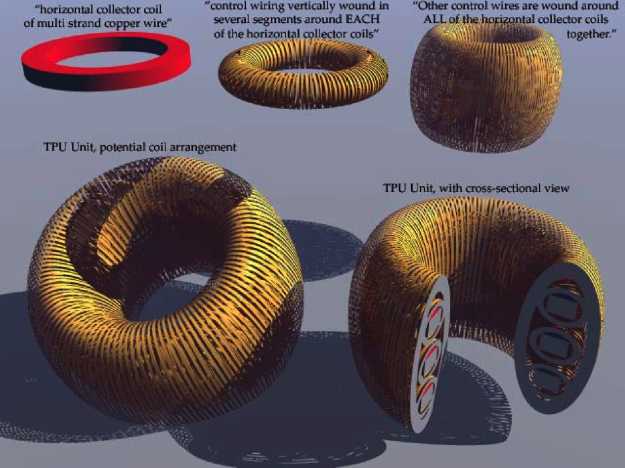 "About the
collector:
"About the
collector:
It is three separate coils of multi
strand copper wire laid one on top of the other,
not interleaved. Three is important.
You can do many things with three coils. You can run them in
parallel, you can run two in series and one in parallel, or etc.
You can run a separate frequency into
each coil for better control on large power units if need be.
The control wiring is vertically wound in several segments around each
of the horizontal collector coils.
Other control wires are wound around all of the horizontal collector
coils together.
Through the different control wire and
coil wire arrangements you can keep complete control of the unit most
of
the time."
(I think the three ring unit, with another set of windings around it
all, helped "average out" spikes and surges, compensating for Mark's
rather
basic control over the conversion process and preventing burnouts. With
microcontroller control, a
single layer might (hopefully) prove to be all that's really
necessary.)
This lengthy and revealing compilation of letters helped
me
understand the whole process of 'collecting' lambda rays better, and
glimpse many of the principles and intricacies of making a practical
working device. I
started to feel I really knew what I was doing in much greater detail,
not just trying to copy exactly something that was somewhat successful.
And sure enough, on almost the next page Mark wrote to Lindsay:
"hope
the
things
I
share
with
you give you ideas about how my unit works.
As you know, I am a great believer in understanding, not copying.
Sincerely,
SM."
Towards the bottom Mark
stressed a few more important details.
"Listen,
you
need
to
make
three
coils or so one on top
of the other. But the important thing is to wrap the control coils
perpendicularly around the
collector coils. [This
90° perpendicular angle is as I had surmised in 2013 from looking
at various
units. Magnetic alignment.]
There need to be three of them all the
way around. start them up one at a time each. [Ah,
that must
be why I've done a three coil driver circuit! I was just copying Otto.
Also I like Otto's technique of wrapping them on plastic(?) spools
instead of directly around a piece of wire. Easier to duplicate, and
they can be shifted around... and there's the possibility one might
just be able to buy suitable coils... eg, if the secondaries need a
thousand or more turns.]
First frequency then second harmonic
component into the second [control coil], then the third.
when you eventually strike the cord look out. you will know what has
happened at that point. In the mean time you can measure a slight
output
even if you do not strike the exact cord." [Not
cord, chord! -- the grammar police.]
[...The DC kick on the kick on the kick. I wonder if that's the actual
1-3-5 major chord of music, the 3rd, 4th and 5th harmonics of a
fundamental tone? Also, if the microcontroller can measure the slight
output, it should be able to tune in the "chord" until the output is
the desired amplitude.]
Another letter
had very similar info.
But he also wrote to Lindsay of being increasingly
pressured and threatened by US federal government agents to cease all
communications on the subject or be thrown in jail. So much for freedom
of speech. They had intercepted and gathered all his e-mails and web
postings without a search warrant. Inventors like Mark who would
change the world would be a main target of such espionage, which
federal agencies were given unbridled "authority" to do under the
so-called "Patriot Act". Federal agents from the
FBI, Atomic Energy Commission (what?!?) and the Department of "Justice"
convened a meeting
with him in his attorney's office. (See TE News #84, In Passing:
Patent System: Far More Disgraceful than I Ever Dreamed! It sounded
just like that.) They claimed to represent the American public, but
they only suggested that such a device might be used "to make bombs" by
"terrorists" -- with no thought of what benefits constructive uses by
everyone might bring. It sounded far more like they represented the
social parasites that continually bleed the public of our hard earned
money to their own enrichment, doubtless trillions of dollars per year.
Those can see that the sources of their unwarranted wealth and power
can go up in smoke at any time if they don't ruthlessly stomp out
energy progress immediately whenever it makes its appearance. Anyone
with ears has heard the stories, and here is one more, this time
related by the victim himself. Someday, if not on this world then on
the next where one is given to see the universe consequences of one's
actions, such people are going to be very sorry and ashamed of
themselves for any part they may have played in these sordid affairs.
especially the instigators.
It is clearly not in the public interest
that low-cost, plentiful, clean, renewable energy should be delayed a
single day longer than technical development and manufacture of safe,
reliable products requires. Social inertia and technical issues will
ensure adoption is slow enough to make the changes without undue social
upheaval.
There were a few more pages with some more interesting
stuff. Some "off topic" letters praising tube stereo amplifiers over
transistors seemed to date Mark back to at least 30 years or more ago.
Then I
hit page 63 of 63 and there simply was no more. The
document was dated 2007. I fear that Mark is probably in jail, held
incommunicado without trial
since that time. Or dead. He's one of a special cadre of "terrorists"
the
corrupt are too afraid of to let them be or even to let them speak or
write, to
whom the special "deemed to be
against the US national interest" (by most any unnamed government
agency) lawless patent "laws" apply. Hopefully I'm wrong. But the
internet will no longer let valuable information be destroyed or kept
hidden from those seeking it. And in the coming time there may be
chaos, but at least evolutionary progress will no longer be
thwarted.
"The truth never suffers from honest examination." - Jesus
http://www.TurquoiseEnergy.com
Victoria BC Canada