Turquoise
Energy Ltd. News #95
covering December 2015 (posted January 3rd 2016)
Victoria BC
by Craig Carmichael
www.TurquoiseEnergy.com
= www.ElectricCaik.com
= www.ElectricHubcap.com
= www.ElectricWeel.com
Happy New Year,
Everyone!
A Highlight:
- Self-turning Magnet Motors are Powered by VHE/Lambda Rays? (see
Month in Brief, Electricity Generation)
Month In Brief
(Project Summaries)
- Unipolar Motor Controller - VHE Lambda Ray Converter - and - Magnet
motors appear to be lambda ray converters! - Chevy Sprint &
variable transmission - Miles ZX40 Electric Truck - Mazda RX7 EV &
battery longevity notes - LED/Aquaponics & Space
Lighting Note & Peltier Fridge
In Passing
(Miscellaneous topics, editorial comments & opinionated rants)
- Lifting the Veil: The Pathocracy (book) - Bail-Ins Coming? -
Techniques for
Suppression of Clean Energy - Peace and Forgiveness - Pluto images
- In Depth
Project Reports -
Electric Transport - Electric Hubcap Motor Systems
* Unipolar Motor Controller: pulse speed control input to improve
performance.
* Hubcap Motors: Rotor Magnet
Attachment
Other "Green"
Electric Equipment Projects (no reports)
Electricity Generation
* VHE/Lambda rays - ideas
* "self turning" magnet motors are apparently powered by lambda rays!
* microcontroller triple timer for the converter
Electricity Storage - Turquoise Battery
Project (NiMn, NiNi), etc. (no reports)
No Project Reports on: CNC
gardening/farming machine, Electric Weel, reluctance motors, battery
making, aquaponics.
December in Brief
As I think back over 8 years of renewable energy
developments, I can't take a whole lot of satisfaction in my successes.
There are components and aspects to it all that have been very
successful, but I still haven't put an 'ultra-efficient' EV on the
road, and I haven't so far made any really satisfactory electrical
generator or a practical battery. Some things, as far as development
goes, seem to be on the
brink of happening, but they've often seemed that way before, then
deficiencies in the ideas, designs, or my physical constructions show
up, and they haven't yet. A major problem has been that as I develop
one thing, I discover something better. It seems unsatisfying to work
on the old thing once I see a better way, so I start on the new thing
instead of perfecting the old. One might also say I divert too readily
into new projects which are only marginally related to what I've been
doing. Sometimes I expect they'll be a short, minor diversion, but they
tend to grow and metamorphose.
The new battery chemistries, NiMn and NiNi, seem to almost
work, but have never quite performed in a manner such as to be
practical. I now have a couple of things I want to try next on them,
but I haven't had time to look at the project in months.
My BLDC motors are great in theory and highly efficient
but so far they've broken down somewhere or other under stress. When
they do I improve the design of whatever piece broke, and they are now
much stronger. But presently the magnets still fly off the rotors from
over-revving. Theoretically I have an improved design for attaching
them, but I haven't made a proper new rotor in quite a long time. The
new unipolar types - the unipolar controller, BLDC4-3 and reluctance
motors, promise great results but still need more work, and now I can't
say I'm proceeding on them at any great speed. And of course if the
reluctance type is better, why finish perfecting the BLDC ones?, which
I might otherwise have done by now.
The variable torque converter has been a bugaboo all
along. It took me years to find a workable design, and there were
always motor and controller problems to cope with while trying to work
on it. And now that I have a theoretically practical design with
the slipping planetary gear (proven to work in Sptember 2012) and large
centrifugal
clutch (can hardly fail... if it's adequately robust and the relatively
low RPM is high enough to lock it), and again, now why worry about the
torque converter if the high-RPM capable reluctance motor shouldn't
even need one?
The off-wheel add-on car wheel drive setup (with belt or
chain
drive to the wheel - TE News #91 & #86) looks like a real winner,
solving the problems of
ruining vehicle handling with extra unsprung "wheel motor" weight, but
I can't make
it without a truly working pancake-shape reluctance motor - or perhaps
a BLDC
motor with
torque converter.
And now having gained a practical understanding of the
whole process, especially as reported in TE News #94, the VHE/lambda
ray energy converter seems like such an important development as to be
worth pushing everything else aside for. Imagine being able to generate
the electricity one needs 'on the spot'. Then imagine also using such
energy
to desalinate seawater and turn vast deserts into gardens!
As the years go on and various things come up, I find
myself somehow with less and less time, and less energy, that I can
devote to all these projects. I
can't help but think that things would go much faster, and projects
would get completed, if I had a helper or two or three. People who I
could give the ideas and designs to who could then turn them into
pieces for assembly into products. Maybe younger people with more
energy. I envy Edison for having had such
resources, a rare state for an inventor.
So far somehow it hasn't seemed to work out. I'm certainly
not much of a manager and I seem to have trouble delegating work. I may
think of doing so initially, but once a design is in my head it usually
seems
easier to do it than to explain it to someone else. And for CNC parts,
doing the design up so it can be made is usually the only step. The
machine makes the part.
Unipolar Motor Controller
The new (purchased) energy return choke coil now ran cool,
but the energy return/flyback diodes were quickly getting hot. I hooked
up the oscilloscope to various points to check voltage patterns and
their relationships with other voltage patterns, and tried a few
different connections like double choke coil and no choke coil. Then I
thought: the diodes conduct all the flyback current spikes regardless
of whether the power is going back to the supply or merely being
shorted across the motor coils. It should be all the same to them.
Eventually I came to the conclusion that things were actually working
as they should, that the diode heat was probably what it should be with
all the high current spikes. They just needed a good heatsink, and
preferably active rectification to reduce the losses. Perhaps I had a
conceptually better unipolar motor controller with half the active
components after all!
I could have it wrong, but an odd "extra voltage" spike
right at turn-on looked to me like the full-current pulsing drive was
imparting some "DC kick" to the motor coils. From Bedini and then other
more commercial motor makers comes evidence of getting something extra
out of motors from pulsed drives. It's explained as being 'the coil's
magnetic field energy is being returned'... but this energy return has
always been the norm. The 'extra' energy may some "DC kick" VHE/lambda
ray
radiant energy being imparted with each pulse.
Later on, with the ground clip in a different place, there
was no sign of the extra voltage pulse. There was a slight drop there
instead. And yet the pulse really wasn't explainable by where the
ground point had been. Main conclusion: looking at and interpreting and
meaning of transient waveforms is complicated and it's easy to jump to
unwarranted conclusions. I didn't know if the pulse was real or not.
And I started looking at how to get more power - increasing peak
current and shortening the OFF times.
I
decided to give it a rest, do some software development, and wire up
the lambda ray collector. Later with Christmas concerts and various
festivities, I didn't get back to it.
But I did start thinking about beefing up the rotors even
more - with a solid cover shell of tough plastic that fits over the
magnets and bolts onto the steel rotor with flat-head machine screws,
clamping each magnet inside a rectangular pocket.
VHE Lambda Ray Converter - and - Magnet motors appear to be lambda
ray converters
On the evening of the 6th I started in on code to read the
serial pushbuttons in the display-controller. I got it going after a
while, after some seemingly inexplicable results that really had simple
causes. (like serial shifting after reading the first bit instead of
before). Over the next few days, I found the multiply, divide and
analog value reading programs I'd done in 2013 and tidied up the code
some, along with reading and learning how to use some complex features
of "timer A" that looked just right for timing the resonant pulses. But
I didn't get things beyond that point.
Hold onto your hat: It would seem that self-turning magnet
motors - some types if not all of them - get "bursts" of magnetic
energy
from VHE/lambda rays. A sudden change in magnetic field as one magnet
flies by another generates a burst of electricity, which converts
lambda rays into another burst of electricity, which makes a burst of
extra magnetism. That's their power.
They are thus a special form of lambda ray converter,
converting the rays into magnetic force leading to mechanical rotation
rather than directly into electricity. From the amount of energy they
seem to make available, they don't seem like terribly effective
converters, but their power would seem to come from the atomic
interactions between magnetism, electron motions and lambda rays. I've
written more on this idea, along with several more ideas derived from
the web about lambda rays, in the detailed project report.
Since the electrical voltage switching types of converters seem to be
much more effective, I'm ending any thought of trying to further
develop
magnet motors myself. (Here at least is one small simplification of
goals!)
Chevy Sprint & variable transmission
This project has been repeatedly pushed aside by competing
attractions that
are also taking longer than hoped. When I got a 300 amp, 36 v Kelly
Brushless DC Motor Controller, I thought everything would work but the
slightest touch of the control over-revved the motor and the magnets
broke off the
rotor - all 12 at once. Then I wanted to put it back together with the
new magnet strapping system to be good for higher revs, but I had just
come up with the unipolar idea and wanted to orient them NSNSNSNSNSNS
for the unipolar controller, instead of NNSSNNSSNNSS for the regular
bipolar one. Why put it back together the same way if I was then going
to change it? Then I found out about reluctance motors, came up with
what seemed like a good design for one and was also given the basis for
a second good
design, and wondered why I would be using permanent magnet motors at
all. Why not
just go for the new type? But the motor controller energy return system
needed work, and so far the whole thing seems to have the power of
about 3 hamsters. As above I was doing some testing this month partly
to see
what needed improvement to get more power.
On the 18th I went to some little used shelves in the shop
and realized... Wait a minute! There's a second Electric Hubcap motor
rotor sitting on the shelf! To run the motor in the Sprint all I had to
do was reassemble the motor with this spare rotor. It's still the old
style magnet strapping, so would be just as prone to over-revving as
the first one, but I could connect
up the transmission linkages so the motor has a load and won't over-rev
without some serious power going into it... and run it at 24 volts
instead of 36. That would also help limit the RPM to a lower value.
That would make it easy to get going on the project again.
I'd be leery of taking it on the street without beefing up the rotor
and using 36+ volts,
but it would at least test out
the planetary gear torque converter with the centrifugal clutch
transmission, hopefully to drive it on the lawn and pinpoint any
weaknesses or flaws in the system. After all, the theory of the
transmission is
good: The planetary gear torque converter part drove the car along and
upslope on the lawn with only about 1 KW of power in 2012. It's my
attempt at implementation I have my doubts about. Especially the
centrifugal clutch seems inadequate and just might fail somehow under
load.
At this point, with so much else to do, I'll probably
await
nice spring weather before continuing.
Miles ZX40 Electric Truck (and MAZDA RX7 EV FOR SALE?)
 I had been
thinking that since I hadn't got the Sprint on
the road, and several factors have kept me from going ahead, and since
the Mazda RX7 EV had such limited range, I perhaps ought to buy a
decent electric vehicle to replace both it and the gas Tercel - if
necessary renting a car for my very occasional longer highway trips.
I had been
thinking that since I hadn't got the Sprint on
the road, and several factors have kept me from going ahead, and since
the Mazda RX7 EV had such limited range, I perhaps ought to buy a
decent electric vehicle to replace both it and the gas Tercel - if
necessary renting a car for my very occasional longer highway trips.
I now have pretty much all 100 AH batteries in the RX7,
but what it really seems to need is something more like 150 AH or
better, in order to supply sufficient current with less voltage drop
and stress as well as to have more actual storage. I figure that might
nearly double the driving range, perhaps to 25 or 30 Km (without
running it into the ground). But unless one ordered the special 8 volt
golf cart batteries (180 AH), which would probably cost substantially
more than buying a common type, one couldn't fit 144 volts worth of
higher amp-hour batteries except with very pricey batteries (like
Li-ion, NiMH).
It crossed my mind that there is one common size, 'frame
31', a little bigger than the '27' size I used. I figure one could fit
6 in the back, and just barely squeeze 5 in the front, for 132 volts
instead of 144. At 145$ each those would cost maybe 1800$ - at least
considerably less than most lead-acid EV refills. But it seemed that
size 27 were 105 amp-hours, while size 31 was 115 amp-hours. Apparently
it would be a very modest improvement. There were some other 12v sizes
up to 150AH, but again they were probably less common and more costly.
A last option would be eighteen 6v golf cart batteries, which would be
240 amp-hours but just 108 volts. The 26 KWH (for 3000 $) would no
doubt give it decent driving range, but performance would no doubt suck.
Anyway, batteries for the RX7 seemed like stop-gap
measures. It's still a leaky beat-up old car with a several things that
don't work, with the motor connected to a lossy standard automotive
transmission.
Then a friend sent me a link to a 2009 low speed electric
cargo truck at "Burnaby Repo" (repo.com) I decided to buy it. I figured
it would doubtless do 50 Km/Hr around town, which, assuming the
practical range
was even 40 Km, would actually take me most places where I commonly go.
It really whined away at higher speeds but went up to 34 MPH on level
ground. The noise seems to be in the transmission gears rather than the
motor.
It wasn't quite what I wanted, but it would surely be more
practical than the RX7. And it could carry lots of cargo. And I figured
I could surely sell it for as much as or more than I bought it for,
electric trucks still being almost unobtainable.
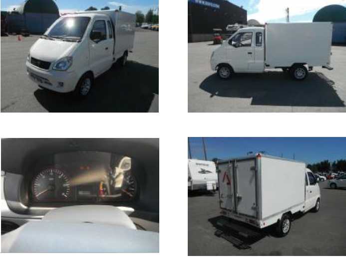
It was a Miles ZX40, which Chinese company I had never
heard
of. It apparently operated from 2003 to 2013 when it went out of
business, making gas and electric vehicles that 'meet vehicle safety
standards'. Several types used a single frame that could be a flat
deck,
pickup, open deck passenger carrier, van or cargo van. The front end of
all of them looked the same. The transmission for the electric was the
same as for gas but stuck in 2nd gear, with no shift lever and no
clutch. (I can't help but feel that would be a significant source of
inefficiency, as usual.) It had a 72 volt AC motor with a variable
frequency drive (VFD).
It was on
sale for around 6000 $C... 10000 $ less than a used iMiev I saw
(cheapest one yet for 16000 $). Similar new models on their web site
(vans
or pick-up trucks - I didn't see another cargo-box style) were around
21000 $US. (I can't help but think that for such a price, if a regular
car would do instead of a truck, an
Mitsubishi iMiev or Nissan Leaf would be better value. At 6000$
it's a different story.)
It has 12 golf cart batteries under the floor of the cargo
cube - half as many as some vehicles. Those would give it 240 AH * 72V
= 17280 WH of energy, weigh somewhere around 62.5 * 12 = 750 pounds,
and cost 145 * 12 = 2000$C (with taxes). Golf cart batteries (having
sodium sulfate in them) are apparently the longest lasting of the
lead-acid types, and if I also used 6 of the pulse chargers for
charging them, they should last quite a long time. Maybe, with luck,
headed for 700 to 1000 charges?
At "Burnaby Repo" it was stuffed into a warehouse with no
room to move. I had no reason to suspect it had problems. But when it
arrived it didn't work right - it worked intermittently, and let me
down on the street a couple of times. But I found that if I unplug the
35 pin cable to the motor controller for a moment it starts working
again. Going by the symptoms it seems to be either the motor
rotation/speed encoder or the wiring to it. This may be one reason it
was more affordable. But I wanted to buy a vehicle, not another
project! I'll cross my fingers and order another encoder (60$) from
Canadian Electric Vehicles (CanEV.com).
I'm not fussy about the Chinese construction. Both the
batteries under the body and the electronics are open to the road
beneath, and there's no undercoating on the body. It already has
some light surface rust in various lower places. Randy at CanEV didn't
think much of it either. I may take some anti-rust
zinc spray paint to it.
Anyway, if anyone wants the Mazda RX7 EV I'll sell it for
2000$... but without my pricey
NiMH
and lithium batteries. Battery option ideas for the buyer I've stated
above. (The electric drive parts are doubtless worth more out of the
car than in it.)
Tercel & RX7 EV battery notes
After about 5 years of use and abuse, the 3 x 10 D cell
(30AH, 12V) NiMH starter battery in the Tercel is now failing to start
the car if it
sits for 3 or 4 days or more. That would be after many thousand starts,
and many hours of waiting at red traffic lights, and coasting down
grades or while slowing down, with the engine idling much too slowly to
keep
the charge up... thus saving the maximum possible amount of fuel, which
at one point (before the NiMH battery) I calculated from fuel purchase
records to be about 10% savings in mostly city driving. (When I first
turned the idle down, with "reconditioned"
lead-acid batteries, they were lasting months, not years.) Hauling
around a 12
pound NiMH battery instead of
a 28 pound PbPb has also doubtless saved a bit of fuel.
My records of battery replacements in the RX7 EV somehow
are lacking - from the time the first piece of paper in the glove box
ran out of room. That's rather pathetic record keeping for a car I
partly have for battery longevity experiments! One of the four
remaining PbPb batteries appears to be giving up the ghost, limiting
the range to under 5 miles in spite of pulse charging it for the last 2
or 3 months. I'll hazard a guess it's been in there about a year and a
half. I'll have to keep better records!
LED - Aquaponics & Space Lighting Note & Peltier Fridge
I watched a video on youtube of an indoor farming project
in an 'abandoned' multi-floor Chicago building - a parkade or
something. LED lights had been donated by GE. It seemed like 90% of
them were red, and only 10% were blue. Using mostly the cheap red LED.s
and only a few of the costly blue or violet ones improves the economics
of making grow lights. Perhaps 3 rows of reds and one of blues would be
better than two of each. But
really I need to find a design that's easier, that doesn't take hours
to assemble. And it needs either better cooling or to be derated from
15 watts to maybe 10. Or perhaps an efficient switching current supply
would sufficiently reduce the heat generated, because much of the heat
comes from the current regulator pass transistor, especially during the
day with the solar panels raising the supply to 14 volts. It's only (so
far) the emitters near the circuit board that start failing.
I also note that for all the claims of longevity of LED
lights, the first LED house lights I made in 2012 don't seem to be as
bright as they were when I put them in. The emitter makers did say that
organic outgassing or vapors from nearby organic materials would
contaminate the plastic and reduce the brightness. If that includes
carbon dioxide, the bit of CO2 in the air probably accounts for it.
That would tend to indicate that the emitters should be enclosed in a
sealed space, or at least one with very restricted air circulation. On
the other hand, some of them might be running too hot, which demands
that they be better heatsinked to the open air they shouldn't be
exposed to.
Peltier Module Fridge
The peltier module fridge is cooling more effectively with
the big 15 amp emitter replacing the 8.5 amp unit. It probably
actually draws around 8-10 amps, the fan inside circulates air
through the fridge, and the outside heatsink fan needs to run at a
higher speed to cool the heatsink. It's been maintaining about 3°
near the ice tray,
which always has ice, and 7° near the top and the far end. I am no
longer concerned that a big tub of margarine or whatever is too warm
for
the long time it takes to use it all. My take is that around 100 watts,
on most of the time (I occasionally shut it off manually for a few
hours or overnight) is a lot of juice for an "apartment size" fridge.
But if
improved COP, long lived peltier modules ever make it to the market
they'll be a game changer. Even 50% higher COP would be most useful,
and with 200+% effective COP they'd definitely start replacing
compressor based
fridges.
In Passing
(Miscellaneous topics, editorial comments & opinionated rants)
Somehow, three topics, written separately and
at different times, fit together like a single narrative. Okay, once I
realized it, I changed a couple of lines to
enhance the effect. It was still completely unplanned. "Bail-ins
Coming?" was inserted on January 2nd after I suddenly realized what is
likely to happen with the banks - perhaps this year.
The Pathocracy
Not too long ago, I noted how people with various
personality defects or disorders had come to be in control of
governments
and the economy almost everywhere. This has been referred to as corporatocracy,
oligopoly,
and
cleptocracy.
 Now a book
called Lifting the Veil, available on line, has coined a new
term, The Pathocracy, explaining how and why psychopaths, just
1 to 4% of the population, have
come to dominate the positions of economic and political power.
Now a book
called Lifting the Veil, available on line, has coined a new
term, The Pathocracy, explaining how and why psychopaths, just
1 to 4% of the population, have
come to dominate the positions of economic and political power.
(Personally, I have a hard time believing that actual,
genetic psychopaths with no soul who only look like normal human
beings, could manage to function in society or that they are such a
large percentage of the population. But the leanings and behavior of
those
who have come to be in charge certainly can certainly be broadly
described as psychopathic.)
According to the last chapters, the road toward
eliminating the power of this group is
education (what else!!), and non-participation rather than
confrontation. Learn what
goes on 'behind the
scenes.' Don't keep your money in the big banks. Choose local over big
corporate. Etcetera. (And I might add, buy as little petroleum as is
workable. I'm sure that would be the best help for the middle east
especially, where wars are being fought for it and corrupt powers are
being sustained by the revenues. Great argument for EV.s!)
For anyone who wishes to delve into this rabbit hole of
power lust, greed, satanism and pedophilia, here's the URL.
(Myself, I couldn't bear to read even half of it.)
Lifting the
Veil - An Investigative History of the United States Pathocracy.
Bail-Ins Coming?
Legislation allowing "bail-ins"* has been passed in most
western lands including Canada. I understand that six European
countries that have "failed to enact" the demanded laws by 2016 are
being taken to court by the European Central Bank (ECB). Why even in
the surreal culture of the early 21st century should banks have such
gall, and such clout over elected governments... and why are they so
concerned about a few holdouts?
I've said ever since Cypress that if a second country
implements "bail-ins", people everywhere will start pulling their money
out of banks, and the global financial pyramid system will quickly
collapse. The banks must realize this. Suddenly I glimpsed the obvious
purpose of them having demanded that all countries enact the
legislation: when their "Lehman Brothers moment" arrives and they can
no longer carry on, bail each other out or save themselves any other
way, bail-ins* and capital controls** are to be implemented throughout
the entire western world, all nations, all on the same day. That way,
no one anywhere will have the chance to pull their savings out.
But how, really, can that save the financial/banking
system? Confidence will still be shattered and all economic activity
disrupted. The gargantuan, ever-growing debts foisted upon everyone
over decades will still be utterly unpayable. The advice for several
years now of many of the same economists who predicted the 2008
collapse of the US housing market at least by 2005-2007 can only be
reiterated: Get your wealth out of the financial/banking system. Buy
any real assets you think will be useful, have some physical cash,
silver and maybe gold. And put aside some good food and water. No one
dares to predict which straw will break the camel's back or when it
will happen, but whenever it does, it will be Earth-shattering.
* "Bail-ins": recapitalization of failing banks by taking (a very
substantial percentage of) depositors' savings, in return for (plainly
worthless) bank stock.
** "Capital Controls": you can only take a little capital - a little of
your own money - out of the bank each day. I think (don't quote me)
it's 300 Euros in Cypress and 400 in Greece, and in Greece there are
weekly maximums.
Techniques for Suppression of Clean
Energy
Moray B. King, electrical & systems engineer who had worked around
the frontiers of physics for decades listed 8 ways that revolutionary
energy inventions have been blocked before they started on the road to
the marketplace.
* Academic Suppression [ridicule by 'experts', etc.]
* Blocking of Funding
* Blocking of Patents
* Litigation
* Threats to the Inventor
* Property Destruction
* Framing the Inventor with a Crime [...but hardly necessary when
trying to patent certain types of
inventions
is
in
effect
already
legally
considered
to
be
a crime!]
* Assassination
These tactics come from academia, business, and black ops.
(Per: Breakthrough Power book by Jeanne Manning & Joel
Garbon)
It is easy of course to become cynical, to give up and
simply accept what's doled out by "the establishment". But in the
coming
times, the establishment as we have known it will wither and be
replaced by one populated with people having the will to the three core
values of quality of life, growth and equality, and having empathy,
compassion and love (values and qualities psychopaths entirely lack).
For the prepared, the
lucky, and for coming generations, hope for the future is brighter than
seems warranted today.
Peace and Forgiveness
On Christmas day in 1914 after 5 months of appalling
slaughter, along 2/3 of the western front the German, French and
British soldiers came out of their trenches into a no-man's land strewn
with corpses and fraternized, singing Christmas carols, exchanging
greetings and photos, cigarettes and chocolates, and even playing
soccer. The high commands on both sides declared this to be treasonous
and subject to court martial. It took until March to get the killing
machine back into full operation. (I'm not quite sure of the timing -
at one point it was dark, so I assume it must have started Christmas
eve, but playing soccer games indicates it stayed well into Christmas
day, perhaps all day. And okay, I'm a
year late for the centennial of that event!)
In August 1914 youth went enthusiastically off to war to
try to
vanquish the nation's hated enemies. After all, they were attacking
inferior, strange
foreigners who spoke other languages - and it was high adventure!
Everyone thought it would be quick, but everyone was thoroughly sick of
war by the time it was over, and war was never contemplated so
lightheartedly again. (The Guns of August by Barbara W. Tuchman
is a good read.)
Today we speak of the
'international community' and the whole world is gradually becoming
well connected. With the advent of electronic communication we are
coming to know, sometimes personally, other members of our human family
in other lands and cultures. We recognize much commonality of purposes
and desires with them. And a single language has become the "exchange
language" that everyone wants to learn to be able to communicate with
others everywhere.
There are, and probably always have been, far more humans
of good will who
desire peace than those few who are hell-bent on destruction. We are
fed up with war after war. But in good-natured or apathetic tolerance,
we
have allowed the few to usurp the positions of power and influence. And
these few ever manipulate and arrange awful situations and "false flag"
crisis events to
arouse our inner fears and prejudices and to have us grant them ever
more power to "protect" us - by commandeering everyones' resources to
fill their war coffers and removing our rights and liberties. Much
of the west is on the verge of becoming dictatorships. (Again it's a
good argument for having to have all legislation ratified by the whole
population with on-line voting.)
Sometimes such twisted people stop and examine their own
motives, methods and goals. Many eventually
revolt. When they do they cease their machinations
and start to recover their sanity. Some start trying to expose and
explain what's going on. When we hear them we feel sympathy for them.
We forgive them. In spite of their past victimizing, they were victims
of a system that asked them to do immoral things in return for
employment. Some who feel powerless in spite of their position,
through various mixed motives, wait until they retire to speak out
against what they've been contributing to. (This seems paradoxical: Why
now, when you have no more influence? Where were you when you were in
charge of so much?)
We should help any we are in
contact
with to start thinking and examining what they're doing. And forgive
them in advance. A peaceful, forgiving environment will help them to
recover their life instead of resisting change for fear of people
who seem to be hostile to them, against whom in their insecurity they
should
build mental and physical bunkers of defense.
Our thoughts and intentions for peace and forgiveness are
more powerful than those for war and conflict. The angels magnify them
and help them to bear fruit and spread amongst open minded people. The
overall consciousness of the world has been rising, and this will
accelerate into the future. The present distressing and depressing
world conditions are the dying manifestations of shadowy greed, avarice
and lust for power, on which the light of day is at last being shone,
exposing them for what they are. The more we have optimism and hope and
concentrate on being peaceable and forgiving, having peace and
forgiveness, and initiating progressive processes
and developments which promote peace and forgiveness, the sooner they
will be
vanquished, even in the hearts of many or most of those presently
working harm.
Pluto: Color Images
I keep hoping for close-up color images of Ceres and comet
67P. Instead, some lovely color images of Pluto are being put together.
This is a reduced, cropped version. See the original for better detail
and coverage.
http://pluto.jhuapl.edu/Multimedia/Science-Photos/image.php?gallery_id=2ℑ_id=389
 Surface features on Pluto in color (reduced,
cropped)
Surface features on Pluto in color (reduced,
cropped)
The things that look like mountains are indeed of mountain
size
scale. They may have been (at the time of tidal disruption) a huge
melted slurry of "ice" blocks floating in liquid, which then froze.
This is judging by their similarity to broken up ice blocks on Europa,
and because they appear to spill over onto the "cantaloupe" terrain
with the wrinkly dune patterns at the far right. Is that similar to
Triton's cantaloupe terrain? Per my tidal disruption theory on the
"Origin of Pluto and Triton" [Somewhere on here:
http://www.saers.com/recorder/craig/]
they
were
once
one
much
larger
body,
and
so
it
may
be
the
same terrain - a bit like Africa &
South America, where one landscape was separated by continental drift.)
The white material (whatever it is - frozen nitrogen?)
appears to be blown from the north to northwest, preferentially
covering faces sloped that direction in the center mountains and in the
terrain at the right, where dunes reminiscent of those on Mars appear
to go right across the polygon edges. (they're clearer in the full size
image.)
All this amazing and windswept geography occurs on an
intensely cold sphere 1/3 the size [volume] of Earth's exceptionally
dull and
uninteresting moon.
In the last part of December, the Dawn spacecraft should
have entered a lower orbit around Ceres (still not very close!). I
haven't had time yet to go see if there are any interesting findings.
Newsletters Index/Highlights: http://www.TurquoiseEnergy.com/news/index.html
Construction Manuals and information:
- Electric Hubcap Family Motors - Turquoise Motor Controllers
- Preliminary Ni-Mn, Ni-Ni Battery Making book
Products Catalog
(Will accept BITCOIN digital currency)
...all at: http://www.TurquoiseEnergy.com/
(orders: e-mail craig@saers.com)
Daily
Log
(time accounting, mainly for CRA - SR & ED assessment purposes)
Dec 1-3: Writing previous newsletter
4: Unipolar Motor Controller tests - oscilloscope readings
5: Study & interpretation of the readings.
6: More readings, more study. Evening/night: Programming code for
MSP430G2553 to read display-controller serial pushbuttons.
7: Continued above. Working (finally!) by early afternoon. Started
studying "timer A" in the MSP - to be used for pulse drive timing
interrupts. Initial write of Timer A interrupt handler.
9: Mor Study: Timer A has mor complex features/modes than most timers.
Looks like the unusual features might be perfect for the lambda ray
converter. I'll have to redo that to take full advantage of them.
11: Mor programming.
15: Traveled to mainland to purchase an electric truck.
18: Bought toy quadcopter EV. HD camera, wi-fi. Wow! It flies - didn't
try camera/wifi.
19: MILES ZX40 electric truck arrived. It didn't run properly. SIGH!
Started troubleshooting it.
20: More truckbleshooting. More figuring out MSP430 TimerA - this time
how the interrupts are handled. (not well explained in datasheets.)
22: Got truck running and drove it a couple of short trips.
23:
24: Truck proved to be intermittent.
25: Wiggled wiring cable and got truck home.
26: Removed a couple of connectors in a wire and soldered it together.
27: Truck quit again. Rats!
28-31: Hey, it's Christmas Holidays!
Electric Hubcap Motor Systems - Electric Transport
Unipolar Motor
Controller
The energy return system in the motor controller seemed to
be the overriding concern. I reconnected the ARM (axial reluctance)
motor. I hooked up
the oscilloscope to various points to check voltage patterns and their
relationships with other voltage patterns. As I did these measurements
and initially copied them in here, I was mystified by a few things.
After a day to reflect, some of them started to clear up, and I've
written both of the initial confusion and the later answers that came
to me.
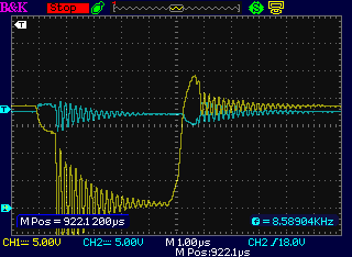
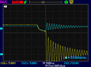
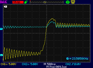
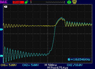
First, what was the supply
voltage before and after the "choke" - the energy return coil?
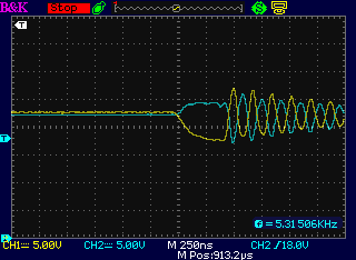
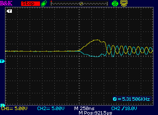 Supply Voltages before (Yw) and after (Bu)
energy return choke
Supply Voltages before (Yw) and after (Bu)
energy return choke
at Motor coil turn-on (L), Motor coil turn-off (R)
Since the voltage for the motor coil is drawn after the
choke, one would expect the blue line to drop at turn-on and
yellow to follow. Why the blue should rise, and somehow the energy seem
to be drawn straight from the supply, is puzzling. Hmm... what's the
"reverse recovery time" of the mosfet body diodes? If they conducted
while reverse biased, that would drag the supply down. Okay, typically
under 40 nSec. The drop comes on more slowly than that, and lasts for
about 400 nSec (the fall time of the motor coil drive), so
that can't be it. And the capacitance across the mosfets/diodes should
be trivial.
Finally I remembered that the main current starts to build
from zero once the motor coil is turned on. It draws no current at
first, so why should the voltage drop? On the other hand... why should
it rise? And what could in the first instant be drawing current from
the battery side of the choke besides nothing?
I hesitate to mention the "DC kick" of a suddenly switched
voltage here in connection with the "wrong project". I would think it
would only explain the blue
line rise, not the yellow line fall. On the other hand, Bedini was
claiming results beyond the expected with his pulse driven motors and
now others are claiming extra energy from certain new types of
motors... and I've chosen to drive this controller with pulses. Now I
read that Bedini actually says the extra power of his motors comes from
radiant
energy. (Per: Breakthrough Power - book by Jeanne Manning &
Joel Garbon.) That would doubtless be correct.
Later I figured out that the apparent dropping of the main
supply (above, yellow) was really the ground reference side rising
(mentioned again below), so if the yellow line were flat at the
beginning of the pulse, then the spike of the blue after-choke voltage
is really its rise above the yellow, making it a considerable 6 or 7
volt spike.
(Maybe this is why the battery seemed to last longer than I expected?
It seems somewhere along the road to the reputed Bedini results.)
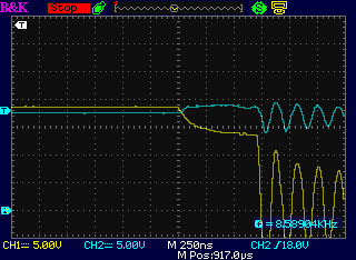
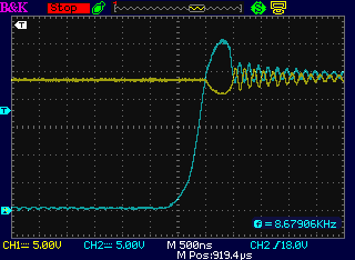
But later again, with the ground clip on the circuit
board, there appeared to be no voltage spike at all - in fact, a slight
dip was seen (below, yellow). Is anything there at all besides
measurement vagarities?
Perhaps it should be noted that there are filter
capacitors on both sides of the choke (>600 & <1000
µF), and that the scope probe grounds are connected at the supply
side filter cap ground. The choked side capacitors' ground goes through
a fat 8" wire to the same point. So the two signals are referenced to
the
same ground point, and unless the scope isn't sampling both
simultaneously, the traces shouldn't be misleading. (If they aren't
sampled simultaneously, why did I spend so much on a new, modern
oscilloscope?) The ringing - apparently back and forth across the choke
- might indicate that it needs more filter capacitors or that the 8"
wire should be eliminated. (What a lot of ringing there is, and
especially in the coil drives!)
At turn-off, the rise of the supply line with flyback
current coming from the coils, compared to the after-choke voltage, is
what's expected and desired.
Of course, all these are very rapid transient effects.
That can be a whole study in itself.
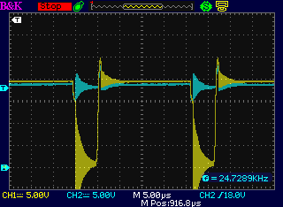
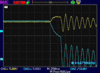
Here are some traces of one of the motor coils turning on and off,
first with the after choke supply voltage - the whole pulse, then the
on and off areas expanded. In all the following traces, zero volts is
one dotted line up from the bottom one.
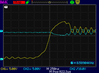
Then with the battery side supply voltage, showing one pulse, then
longer time to show the spacing between pulses. The energy return
flyback diodes prevent the coil from rising much above the supply
voltage.
Perhaps there's a clue to what's happening in the nearly identical
voltage drop of the supply and the motor coil in the first 1/2 a
microsecond after turnon? In fact, I think that's it... both voltages
are referenced to "ground". As the mosfet turns on, it draws current
from the ground line. So the apparent identical drop in voltage of both
the power supply and the coil at turn-on would actually be a transient
rise in the ground reference voltage.
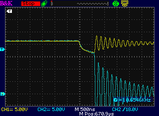
Finally here are on and off with the choke removed - the one supply
line to the motor coil.
There's no separate "after choke" line to get a pulse of voltage into
as the coil comes on. And when the diodes conduct current to return the
energy, they merely short out the motor coil flyback, heating the coil
instead of returning it to the supply.
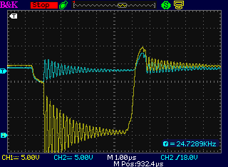
On the 5th I put just one choke coil back in, 750 or 800
µH, and again checked the waveforms on the scope. The differences
from using the two parallel chokes making 400 µH were fairly
subtle. Here's the supply before the choke and one coil (colors are
reversed from above).
One significant apparent change that I note is that there seems
to be lower diode drop voltage from the motor coil to the supply at
turn-off.
And after the choke, same coil.
(Hmm... the 500-700 nS delays at turn-on and turn-off - the switching
speed - may change with the gate resistor value, now that I think about
it. At least, it's supposed to. I should probably go over the old IR
app notes and see whether I should reduce them, increase them, or
they're about right.)
And why in all of these traces does the bottom end of the
coil seem to sit about a volt above its supply voltage when idle?
Perhaps it's one .7 volt forward diode drop, and over a longer
timescale the coil voltage would drift down to its supply voltage.
As to the immediate concern, it would appear that the
energy return system actually is doing its job. The first fix would be
good heatsinks for the energy return diodes, and the second would be
active rectification to reduce that heat.
I note in these drive pulses that they are only 5
microseconds long, with 25 microseconds between pulses. With a good 25
volt supply the average current might hit 20 amps. Thus a continuous
drive then be 100 amps. It would seem the peak currents will have to be
permitted to rise much higher, or the 20 microsecond OFF time
shortened, or both, in order to obtain an average current of 200 amps
to run a motor at 25v*200a=5KW.
If the pulses build up to 200 amps in just 5 microseconds,
they should decay in an similarly short time, so shortening the 20
µS OFF time to under 10 µS, if not to 5, should be
feasible. But maybe I should check the BLDC4-3 motor too and see what
it does?
With the ARM motor connected (and turning no great speed,
hence little back EMF) the coil pulses are only 5 microseconds long,
and the rest period between them is 20 microseconds. The 15 amps max
would be 75 amps if there wre no rest periods. That's at least headed
towards the 200 battery amps that (at 24 volts) would indicate the
desired 4800 watts. That was right in the middle of the desired rest
period duration. The surprise is how fast the current builds up and
shuts off the drive pulses. Could the current sensing be faulty?
At 15 volts with the Honda battery, the pulses lengthen to
6.4 µS, and the total period to 28 µS. I cut the current
sense shunt in half (electrically speaking). The pulses doubled to 13
uS
and the period lengthened to 35 uS - which is still 22 uS dead time.
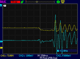
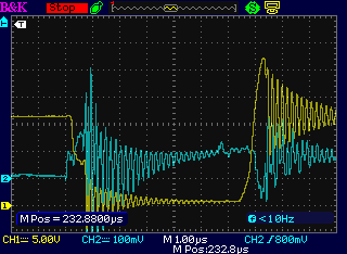 I put one
probe on the voltage sense resistor. There was more ringing than
anything else. I moved it to the R-C filtered side, where the
motor controller chip senses it. Still lots of noise (and straight
across a
.1uF capacitor!), but one can see the sense pin voltage rise from 0 to
.1
volts (blue, .1v/div) and then the pulse shuts off. One sees the sense
transiently go negative with return energy. (I should have followed the
trace farther
along.)
I put one
probe on the voltage sense resistor. There was more ringing than
anything else. I moved it to the R-C filtered side, where the
motor controller chip senses it. Still lots of noise (and straight
across a
.1uF capacitor!), but one can see the sense pin voltage rise from 0 to
.1
volts (blue, .1v/div) and then the pulse shuts off. One sees the sense
transiently go negative with return energy. (I should have followed the
trace farther
along.)
I tried a few positions across the
current shunt, using it as a variable resistor. Lower resistances
seemed to perk things up a bit, but at that point I was running off the
10 amp power supply, so the effect wasn't large. But definitely if one
expects to anything like 200 amps of average current for the intended
4800 watt motors, allowing a much higher peak current is necessary, and
the current pulses are going to have to be relatively closely spaced.
But early in the month, I turned my attention to
microcontroller programming for VHE lambda ray conversion, and later
Christmas and other year-end events intervened.
BLDC Motor
Rotor Magnet Holder
I started thinking about
beefing up the rotors even more than better PP strapping. How about a
solid cover shell of tough plastic that fits over the magnets and bolts
onto the steel rotor with flat-head machine screws, clamping each
magnet inside a rectangular pocket? It could be up to 1/8" thick over
the magnets and still theoretically leave a 1/8" or better gap between
the 1/4" center wall and the shell with a 1/2" (or wider) flux gap.
Somewhere it would still need 'fins' to blow cooling air outward, but I
can think of a couple of potential arrangements. One is to simply make
the plastic thinner than the gap. Then the magnets will still be 'fan
blades'. On the other hand, it would be strongest if the plastic
pockets are the same depth as the magnets. The more I think of the way
the magnets broke off the rotor in the Sprint the more I think I like
strong.
Then, what type of plastic? I occurs to me that kitchen
countertop laminates are strong and rigid. Some of them are fairly
thick - not thick enough for the whole thing, but perhaps thick enough
to be the cover over the magnets (and under 1/8"). Then the main piece
would be perhaps PVC or lexan (something glue will adhere to) the same
thickness as the magnets, with the square magnet holes going right
through it, and the top, solid laminate, covering the holes.
A short term advantage to doing it this way would be that
the magnets don't need to be glued to the steel rotor. For the first
one, I could arrange them in traditional BLDC configuration for the
Kelly controller, and then assuming I get the unipolar controller
working well, I can take the rotor apart and change them.
Electricity Generation
VHE/Lambda Ray Energy Converter
Some Thoughts, Info, on Lambda (λ) or "VHE" Rays
First... the name? Calling rays orders of magnitude above
gamma rays "gamma rays" is misleading, even qualified as "VHE gamma
rays". It distorts thought and study on the subject. It was once
thought that the gamma ray
bands were the top end the electromagnetic spectrum. Hence any rays
found above those bands could only be higher frequency "gamma rays".
But the rays are qualitatively different, like infra-red rays (eg
3µm) are qualitatively different from ultra-violet rays (eg
300nm). In fact, the lambda and gamma bands are much farther apart in
frequency than that. This is why I unilaterally retitled them "lambda
rays".
It seems to me now that in case one doesn't
like that name for terra-electron-volt and higher (TeV+) rays, one
could drop the misleading term
"gamma" (γ - MeV to GeV range rays) from "VHE gamma rays" and just call
them "VHE rays". Or
perhaps "VHE lambda rays" would trigger recognition of the "VHE" term
in physics and astronomy
circles without applying the "gamma" misnomer.
(A similar distortion of sorts occurs in the metric
system. It was intended to be scalable. This seemed to work down to the
smallest sizes of nanometers and even picometers - sub-atom sizes. No
one speaks of "15 millionths of a millimeter". But when scaling up,
beyond kilometers, even space scientists have subconsciously yielded to
familiarity or "force of habit" and speak of distances in the solar
system as (eg) "millions of kilometers", thus splitting up the scaling
factor into two places, instead of either as "billions of meters" or as
"gigameters". The moon orbits 400 megameters from the Earth. Even the
spelling checker doesn't know these words! But I digress.)
---
Next is a thought on detection: Different parts of
the electromagnetic spectrum have qualitatively different radiative
effects. For
example, a radio tuned to the 30 meter band won't tune into or detect
visible light rays at 500 nanometers, and a photosensor won't react to
radio rays. Likewise, with lambda rays at perhaps 1000-100000 times
the frequency and energy of gamma rays and again having qualitatively
different radiative effects, it seems likely that typical gamma ray
detectors
aren't going to detect lambda rays. As Dr. T.H. Moray said, the most
powerful radiative energy has been unknown because we lack the
"reagents" needed for its detection.
Today that statement needs revision: terra-electron-volt
rays were detected in 1989, and rays at up
to 2.9*10^27 Hz have been detected within the last decade.
(There's more on such developments below.)
But how much do we know about their intensity - the strength of the
"CLBR" ("cosmic lambda background radiation"), or about its strength
coming from our own star? I'm sure it's very little.
Each photon is of course far more powerful
than those in any other band, but it's mainly (or only) from the fact
that people
over the decades have obtained powerful electrical outputs we can infer
that it is very strong. Scientifically, however, AFAIK it hasn't been
measured and there is probably no instrument currently existing capable
of making such measurements.
Perhaps related, I expect that Dr. Gustav LeBon's theories
that radioactivity in matter is likewise caused by such high energy
rays will someday be proven correct - that atoms (below atomic number
101) don't just blow up on their own at specific half-life rates. An
external energy source is disrupting them.
---
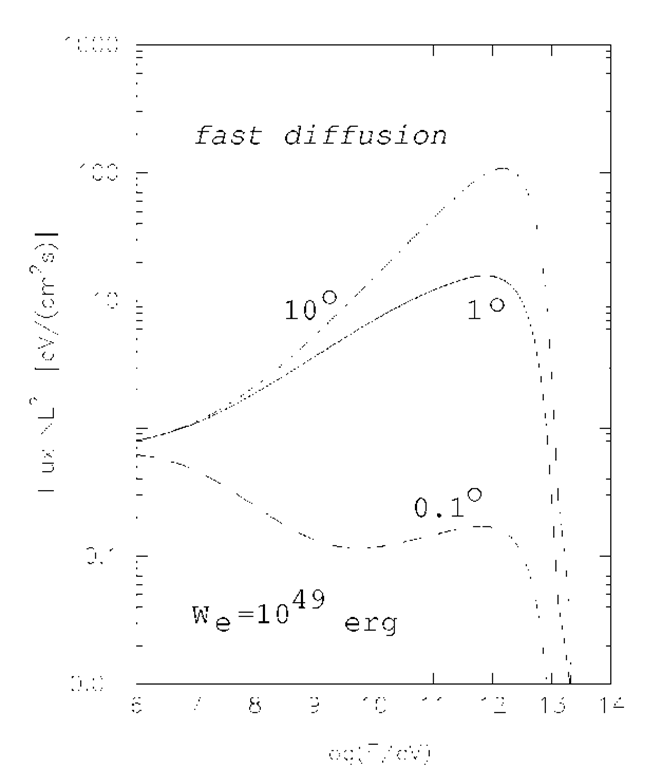
I found this article: Probing the Sources of VHE CR Electrons
(Cosmic Gamma Radiation)
http://what-when-how.com/cosmic-gamma-radiation/probing-the-sources-of-vhe-cr-electrons-cosmic-gamma-radiation/
Well, I wont try to explain things I don't understand, but
this had some interesting (if poorly reproduced) graphs. Considering
their all-inclusive title "VHE CR Electrons (Cosmic Gamma Radiation)",
the relationship between "electrons", "cosmic rays", "VHE" and "gamma"
rays seems hazy. (Electromagnetic rays are of course photons, which
are not cosmic "rays" (charged particles) nor electrons, but which
may release electron-positron pairs.) This ambiguity
may stem from the still only vague realization that the electromagnetic
spectrum doesn't end with gamma rays.
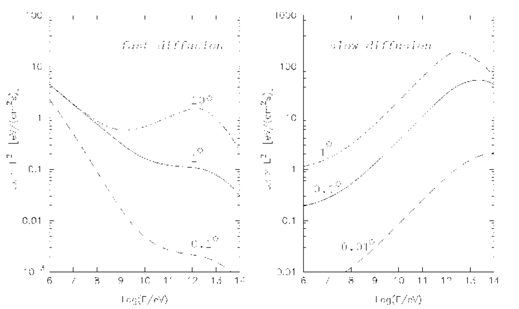 Distribution of high energy "electrons"(?) with
different assumptions of how they diffuse in the interstellar medium.
Distribution of high energy "electrons"(?) with
different assumptions of how they diffuse in the interstellar medium.
Note the concentration of energy in the lambda ray band, perhaps around
10^12
to 10^14 or 1 to 100 TeV
(1-100 trillion electron volts and perhaps centered on 10 trillion) in
the right graph.
As people have obtained very substantial electric power from such
radiant energy,
perhaps we may assume that the "slow diffusion" graph is more the
actual case.
Another "fast diffusion" graph would see major
attenuation of ten trillion electron
volt and up photons, yet the highest energy levels of all around one
trillion.
I'm not sure this article was intended for the layman. Of course we all
realize the implications of the following statement which specifically
seems to specify VHE lambda ray energy levels:
"Above several GeV, Compton and synchrotron losses dominate over
bremsstrahlung and ionization losses."
...don't we?
---
High Energy Gamma Ray Sources (Cosmic Gamma Radiation)
http://what-when-how.com/cosmic-gamma-radiation/high-energy-gamma-ray-sources-cosmic-gamma-radiation/
This extensive treatise gets into measuring techniques,
specific astronomic sources of "MeV" and "GeV" (mega- and
giga-electron-volt) gamma radiation, specific space missions, etc.
While undated on this web page, it is rather dated as it mentions
nothing beyond 2003. But it
looks like a good overview of the whole subject area, at least as it
was known in 2003 or 2004. One "TeV"
(terra-electron-volt) is as high as they consider - as I see it, the
bottom end of the lambda/VHE ray band.
(I note with some disgust that scam ads for "Magnetic
Generator? $49 - Eliminate Your Power Bill Easy Do It Yourself. Great
Discount Now!" appear within that article's space. Note the "?" after
"generator". All they give you is links to stuff you probably already
found for yourself if you were interested, and instructions, plans or
drawings that leave out vital details... because they won't work
anyway. Yes I fell for one of those once. Why is nothing done to stop
these con artists, who could easily be located and shut down? Because
the "powers that be" approve of anything that causes confusion about
"free energy" and tends to discredit the entire subject, so they choose
not to investigate. They probably
collect tax on the proceeds.)
---
Below is info from a presentation for a talk from 2005
says that [one?]
terra-electron-volt rays were seen in 1989: "TeV Gamma rays from Crab
Nebula: 1989", and says that a new generation of instruments is needed
for observing VHE rays. 1989 is much earlier (if only 1/10th the
frequency/energy) than the 2007 date I found with the 2.9*10^27
Hz (~10 TeV) observed figure. The presentation predicts the dawn of a
new golden age of TeV "gamma" ray astronomy using Cherenkov telescopes.
It seems to figure the dividing line between "HE" gamma rays and "VHE"
rays is at 100 GeV, 1/10th of a TeV. (How come my search results are
hitting these older links and not newer ones? Anyway, this is much
little known info even if it may be a little out of date.)
VHE gamma-ray astronomy: observations
http://www.unizar.es/taup2005/Charlas%20Speakers/05%20-%20Miercoles%2014%20Septiembre/T20050914%20-01-%20Martinez.pdf
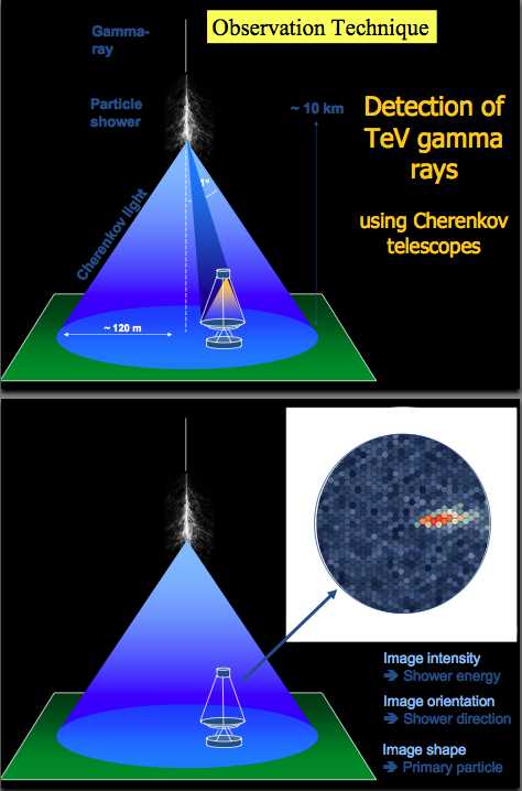
It also sheds light on a possible reason VHE rays seem to
come from all directions: scattering by Earth's atmosphere.
"shower Detection of TeVgamma [lambda] rays using Cherenkov telescopes"
And yet, doesn't the ray have to reach the ground intact,
and its shower of particles occur inside the wire, in order to be
utilized? Perhaps rays 1 TeV and lower are scattered by the atmosphere
but the 10 and maybe 100 TeV rays go right through? Or perhaps only the
occasional ray interacts with the atmosphere?
If it is assumed that most rays are absorbed in the
atmosphere and they aren't, the amount of energy available at Earth's
surface in a little-diminished band could be grossly underestimated. I
suspect that the density of energy in the VHE bands is unsuspected by
the astronomic community.
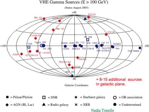
There is also an interesting chart of sources of VHE rays,
here defined as
being 100 GeV and up. If these sources are where the energy comes from,
it
would seem to explain why VHE/lambda ray converters evidently work day
or night. (Or does most of what we get come from our own sun? Maybe I
should look up TH Moray's Sea of Energy book and see what his
ideas were?)
---
A cable TV technician came to the house one day. They deal
with long 'transmission' wires... so I asked him if he had heard of the
"DC Kick". He
had. He also knew nothing about 'free energy', so that wasn't the
connection. I still have found nothing definitive about the kick, but
it certainly sounds like it's real enough. It sounds like one of those
things no one writes much about because they don't really understand
it, and
it doesn't seem like anything really important, so it gets mentioned
casually to new workers when they enter a field where it needs to
be known. Then again, one of Mark's e-mails said there were trade or
scientific journals with articles on the subject, that he had cited to
his
correspondent. I wonder how to find those? If only it had a more
distinctive word to search on in its name.
---
Magnet Motors are VHE/lambda ray converters?
Finally, here's what I think is a "game-changing" idea. In TE News #92
I mentioned a 'youtuber', "MotionMagnetics", who had posted a lot of
info on self-turning permanent magnet motors and (as I recall) said
that there were three essential types. Especially for one type I
remember him saying that in a successful motor, there was a sudden
burst of extra magnetism that helped propel the rotor on its way. This
seemed surprising. Where would that come from?
But here's a connection: moving magnetic forces induce
voltages into nearby metal... not only into copper wires to make
generators, but eddy currents into any solid metals including into
other magnets. A powerful enough, sharp enough flux change (such as
passing by a magnetic shield to suddenly enter into full supermagnet
strength flux) could cause a sharp enough change in voltage, in
electron pressure within a piece of metal, that the "DC Kick"
conversion of lambda ray photons to a shower of electrons and positrons
would take place. These particles would generate electric eddy
currents, which would create more magnetism, most likely an "extra"
counter-magnetic field: the magnetic burst that makes the magnet motor
work.
Ergo, it would seem that magnet motors - at least those
making use of the 'magnetic burst' effect... which just might be all of
them... are in fact getting their rotational energy from lambda rays
and are thus a special form of VHE lambda ray radiant energy converter
rather than a wholly separate type of energy source. Even ones like the
V-gate, which seem to work because a cam pushes the stator
magnet out
of the way at the critical point when reverse flux would otherwise
stall the rotation, may actually work because the suddenness of the
motion and
change of flux when the cam drops the magnet, causes a magnetic burst
at
that point.
So, those who say repetitive work can't be done by magnets
without an energy input are probably vindicated. But people have made
magnet motors that run. They just
don't work for the reasons the proponents and builders think: there
actually is an unsuspected external energy input.
Having seen the difficulties of getting a self-turning
permanent magnet motor to work and the low power outputs available from
them, versus the high powers from the oscillating coil types of VHE ray
converters, I think I'll continue to concentrate
on the latter and forget about self-powered magnet motors.
OTOH, an understanding of how such magnet motors are
actually powered could lead to design improvements that make them much
more powerful and practical. This could have great potential. It seems
to me for example that an
outboard motor that turns itself with no electrical supply or motor
controller, its speed governed simply by mechanically moving something
near the rotor to adjust the field strength, could have great practical
potential.
Then there are "Bedini" and other "hybrid" sorts of motors
that seem to
get extra radiant lambda ray energy as they switch their coils on and
off. One of them seems to greatly improve the battery range of certain
e-motorcycles over what is normally expected. (the "Zero" motorbike,
IIRC?) And why not? Fast
switching of coils is the best technique to convert lambda rays. (I
need to do more testing to see if my 'full strength pulse' unipolar
motor controller and reluctance motor combination is actually getting
this 'extra kick', or if it's just some trick of the high frequency
measurements. And I could try it with the BLDC4-3 motor, too.)
---
Meanwhile, back at the project...
Pulse Timing Made Simple? Triple timers in the MSP430
microcontrollers
Looking at the "Timer A" datasheets - one of the
several complex devices integrated within the MSP430G2553
microcontroller chip - it had "hidden" within it two "extra" interval
timers along with the main one. For a while this seemed confusing and
complex, but really it's like having three timers in one. The more I
explored it, the more I began to realize the brilliant design behind a
system where multiple output timings are performed in hardware, but
right after each change in output, there's one CPU interrupt to set up
the next time period under program control. Somebody really knew what
was needed and figured out in fine detail how to get it. Someone tells
me this system was first developed at Motorola, the same place that
came up with the fabulous MC6809 and MC68000 microprocessors in the
late 1970s -- and might we suspect, probably by the same brilliant
designer?
And in fact, the chip has two such triple timers built in!
This seemed perfect for the triple-transformer/coil converter, where
each one is driven by a frequency in resonance (or nearly so) with the
other two, forming a "chord". With a single counter, I'd have had to
have a "quantum" time when the micro was interrupted and did all the
counting for each frequency, incrementing three numbers until each
overflowed, at which time a transformer coil would be switched on or
off by software and the next time interval would be loaded.
With the triple timer being also a hardware counter, each
of the three intervals would be added to the current timer count, then
stored in its end count register in the timer, almost like before. But
the timer/counter would then count up automatically. No CPU interrupt
is needed until each interval ends, at which time the appropriate
coil/transformer would be turned on or off and the next interval length
would again be added to the current count to be the new end count. Thus
the timer/counter features allow there to be just one interrupt per
each pulse length interval, instead of so many I feared the MSP430 just
might not be able to handle the pace.
Then as I was trying to write the interrupt service
routines, I started thinking: there was something in the datasheets
about outputs from these timer compare registers, and different mode
settings for them. If these came out to pins on the chip, they could be
used in place of simple port outputs and could toggle the output in
hardware at exactly the right time, without a short but uncertain
length of delay while the CPU answered the interrupt. (The interrupt
service routine (ISR) should easily manage to put the next time value
into CACCRx long before the next switch time.) This might be a bit
nit-picky, but it would be the "proper" and more exact way to do it. I
looked at the pinout of the MSP430G2553. Some of the many
bizarre names on some of the pins said things like:
Pin 4: P1.2/TA0.1/UCA0RXD/UCA0SIMO/A2/CA2
So if I set everything up right, pin 4 could be TA0.1 --
presumably TimerA0's TACCR1 output. Then I looked at the pins I had
actually chosen to drive the coils: 11, 12 and 13. In additon to being
P2.3, P2.4 and P2.5 (as stated on the part in the Eagle PCB layout
files), they could be TA1.0, TA1.2 and TA1.2 (wasn't shown there, but
it was in the datasheet. Lack of the full pin designations on the Eagle
part fooled me into thinking that the pins I was choosing couldn't be
used for anything but general purpose I/O port pins, so there was no
point delving deeply to make sure I wasn't selecting pins that would be
more valuable as something else. ...but probably academic since I
didn't know what I was doing with the timers anyway.)
Too bad the middle one wasn't TA1.1. Not quite
ideal, but if I set it up right I could pick the second timer (TA1) and
have two of the three outputs driven by the hardware, eg:
11. TA1.0
12. TA1.2
13. P2.4 (software switched)
Considering I didn't know what I was doing, I did well to
get two out of three. And just how close do the
frequencies have to be, anyway? Switching one in software certainly
should be manageable - a new circuit board is not yet! But it will be
at some point and I'll shift pin usage to make it all hardware
switching. When I was half my present age, I used to delve into every
minute detail of the specs and operation of a piece of digital logic
and be sure
I had every minute parameter of the whole circuit within specs and sure
to work. Now I gloss
over the details like everybody else, and cludj my way through. Of
course back then, the functions contained on this one microcontroller
chip would have been spread across maybe a dozen chips. Each pin would
have one exact function, and each component/chip would have seemed
individually much more important and worthy of scrutiny - which is of
course not the case.
And in fact, one of the lines is one of the two traces on
the board connected with a jumper. Removing the jumper and soldering in
a somewhat longer (still short) length of fine wire can change it from
pin 12 to any unused pin. Pin 14 is unused and can be configured to be
TA0.1. That uses up both timers to get all exact timed hardware
switching... is there some other use for the other timer? Or, I could
cut a trace to the display-controller and liberate a pin that can be
TA1.1. That would be more ideal.
Hmm... now a trace cut and two jumper wires. Still faster
than doing a new PC board, and (so far) not too messy! Looks like the
way to go. I removed the jumper, cut the trace, and simply swapped pins
10 and 13 by soldering on two fine wires.
The timer now connects:
10. TA1.1
11. TA1.0
12. TA1.2
The Display-controller now (SPI) connects:
4. P1.2 - Data In (from DC)
8. P2.0 - Data Out (to DC)
9. P2.1 - Serial Shift Clock
13. P2.5 - Shift/Load Enable
I fixed it on the schematic, and in theory on the PCB layout too, but
it's hard to route them single sided without more jumpers, so I
may revise it again before I make another board. (Using pin 7 [P1.5]
instead of 13 [P2.5] for the DC would help.)
On the 30th I jumpered across the voltage regulator so it
could run with a 5 volt supply. I hope that's enough for the power
circuits and the VHE rays. I also found and (in Eagle for the next
board) corrected a mistake - the Display-Controller was powered from
the wrong side of
the regulator. The 12 volts would have blown it. It all comes of
changing the design as you go for "version 1.0".
Next
(29th) The next step will be to try out the PC board, with
a 5.0 volt supply. I'll modify the display-controller drivers to use
the I/O pins selected on the converter board rather than on the
"launchpad" development board, program the MSP430 and plug it into the
socket on the converter board. Then I'll see what surprises await.
Hmm... where does the chip get its clock from? (When I was designing
the board was probably a better time to ask that question!)
Once the board is running properly, probably the biggest
task will be to sweep through a frequency band with only one coil
running and find resonances, frequencies where the DC kick creates the
highest voltages. Presumably the first coil can then be set to the
maximum point, then the other coils can then be set to harmonically
related resonances to that. ...Or, might each coil have its
own set of resonances? I had best sweep the frequency band with each
coil separately and find out.
Now, how to go about that? With non-symmetrical pulses,
there's a host of possibilities for setting the ON and OFF period even
for one frequency. And then the frequencies are to be varied ad
infinitum.
With a 'real' computer I'd just put the result for each frequency into
a table for later analysis. This microcontroller however has a very
limited RAM memory space - a ridiculous 512 bytes instead of billions,
which will quickly be filled. (Even in 1986 I put 32K byte SRAM memory
chips into my 8/16 bit control systems! Not to mention 64K DRAM.s!)
Some sort of processing and checking results is going to have to be
done, repeatedly, each time the mini-table is full during the frequency
sweep. Only the high and low points can be recorded.
Then, I think, when each sweep is completed, the peaks and
dips should be reported to the user via the display-controller. Perhaps
I'll use the top 3 buttons to initiate a sweep on each of the 3 coils.
Maybe one of the bottom ones plus a top one to have the results display
repeated.
This is going to take some doing, but the resonant pulses
are the heart of the system and I want to explore them relatively
thoroughly. If it can be made to "learn" to configure itself to various
configurations of coils and wires of different lengths, it will make it
much easier for anyone to make up a converter.
http://www.TurquoiseEnergy.com
Victoria BC Canada