Turquoise
Energy Ltd. News #96
covering January 2016 (posted February 2nd 2016)
Victoria BC
by Craig Carmichael
www.TurquoiseEnergy.com
= www.ElectricCaik.com
= www.ElectricHubcap.com
= www.ElectricWeel.com
Month In Brief
(Project Summaries)
- Hands-On Democracy - Electric Hubcap motor, Chevy Sprint &
variable transmission (January's main focus) - NiNi Battery Chemistry:
salt bridge? - Bitcoin Miners/Mining
In Passing
(Miscellaneous topics, editorial comments & opinionated rants)
- Sea Levels Rising - Bank Problems Rising ($)
- In Depth
Project Reports -
Electric Transport - Electric Hubcap Motor Systems
* Electric Hubcap Motors: Rotor
Magnet Placement Jig, motor rebuilt with improved rotor.
* Variable Torque Converter Transmission/Chevy Sprint car
- installation progress: several essential parts made and
installed.
- Test shows centrifugal clutch doesn't engage well enough
at the low RPM.s involved: right idea but not good enough.
Other "Green"
Electric Equipment Projects (no reports)
Electricity Generation (no reports)
Electricity Storage - Turquoise Battery
Project (NiMn, NiNi), etc. (no reports)
No Project Reports on: Lambda ray
converter, CNC
gardening/farming machine, Electric Weel, unipolar motor controller,
reluctance motors, aquaponics.
January in Brief
I may be getting some money to help foster the
projects. The donation is to allow others to commit some of their time
to
assist. If it comes to pass, this will be an exciting development! I'll
have to
organize myself and the projects so as to put this blessing to best use.
I did nothing on the radiant energy receiver. It's surely
the most valuable energy project to get working, but I really wanted to
finish and test the variable speed transmission drive in the Sprint
car, which has sat mostly done for months if not a year.
Diverting again, I spent time in December and January at
last
getting my bitcoin miners running. This would have been better done
last spring, as the network difficulty was increasing so fast that by
January the bitcoin rewards from the mining pool didn't exceed the cost
of the electricity to run the miners, which, doing hundreds of billions
of complex calculations per second, use hundreds of watts. If
the big banks fail and their tens of thousands of bitcoin miners go
off-line, or if the price of bitcoin rises substantially, or if there
are free radiant energy converters, mining may
become profitable for the thousands of "little guys" again. On the
other hand, if the mining pools shut down, one will have to figure out
the added complexities of doing solo mining.
But it can still be still virtually free electric heat, if
one can put up with the fan noise. I've even hatched a plan to pre-heat
the hot water with them, blowing their warm-to-hot air through a box
with a
copper water tank in it. In the financial sense, it's "free energy" -
the same electricity but having a payback.
After months of working on new 'BLDC4-3' and reluctance
motor types and new 'unipolar' motor controllers, and figuring out how
to make a VHE lambda ray energy converter work, I decided it was really
high time to get back to the Electric Hubcap motor with the variable
transmission to make the 'ultra-efficient' Chevy Sprint car EV. Theoretically
there was nothing to stop it from working properly. Of course various
things could still go wrong. Especially, as half expected, the
centrifugal clutch proved to have insufficient grip at the RPM.s
involved.
The first step was to get an Electric Hubcap motor rotor
that would stand up to the Kelly controller. If it has no finesse at
low power and spins my motors madly at the slightest touch. It also
promises to be able to supply levels of torque and power that seem to
make my BLDC controllers burn out transistors - also meaning, levels
that could potentially put a car on the road.
Hands-On Democracy
Again diverting from energy projects, I decided to
write something to tie all my 'political structure' ideas together. I
started
thinking of a book, but later decided on a web site by the same name,
which may be: Hands-On Democracy - How to run a world. It
focuses especially on how decision making and voting can become much
more direct, by citizens, now that we have the internet. While we still
need chief executives and legislatures as well as judicial systems, we
certainly don't need to delegate so much power to them that they become
our rulers, looking for political spoils, instead of our
representatives and servants. Today we should be able to implement
various forms of direct decision making and citizen
ratification of governmental acts that retain control of the agenda and
really reserve final power to the people themselves - ourselves.
This may seem radical, but is it not a major tenet of
democracy that government should be of, for and by the people? That was
considered very radical in 1776 and there were surely plenty of people
who thought the experiment would be a speedy failure. It has only very
gradually been failing, and that because there was no realistic
provision for growth and change. It hasn't evolved along with the
advancing civilization it spawned, and unscrupulous people have figured
out how to twist and divert rigid political systems to do their bidding
instead of doing what's best for society. It's time now for that lack
of evolution to be remedied by changes that will restore final powers
of decision to the
people, who governments are supposed to serve.
I ended up writing a considerable introduction to the
subject. As I did so I became convinced that that may be the most
needed part considering that most people have given the whole subject
area little thought, and also to provide some broader perspective. We
habitually look at everything through the narrow, distorting lens of
our
enculturation. Meaningful change is hardly possible without being able
to view the subject from a broader, more objective viewpoint - to look
in from the outside.
As I was writing the intro, I started thinking of
narrating it as a video and uploading it to youtube. It will doubtless
reach far more people that way. But as for January, it was just one
more
unfinished project.
Electric Hubcap motor, Chevy Sprint & variable transmission
I really wanted to get this project, this unfinished
business, going again. I really do want the "ultra-efficient" car. I
had misgivings about the centrifugal clutch, but there was nothing to
be done with it until it was tested... after all, it just might work.
With
a new motor rotor I could reassemble the motor and get back to
the rest. But I decided I didn't want to just use the other similar
rotor, potentially subject to the same problems. Much of my trouble has
come from not building things robustly enough. In the last issue I
mentioned some ideas for improving the
rotors.
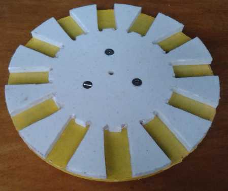
 I
made the magnet placement jig I've been meaning to do
for so long, and a template to draw the strapping slot positions on the
rotor with felt pen.
I
made the magnet placement jig I've been meaning to do
for so long, and a template to draw the strapping slot positions on the
rotor with felt pen.
But when at last I went to rip the broken rotor apart
(14th) and recover the magnets from it, I found there was a good reason
it had come apart: the disk had been given a spray-on zinc anti-rust
coating. I had previously discovered on the first Electric Caik motor
that that spray-on zinc coating was feeble and would rip apart across
its whole surface as soon as the motor hit any decent RPM. This rotor
had been made just before the first Electric Caik. Somehow it had
lasted until I tried it with no load with the Kelly controller, which
had spun it up to high RPM.s almost instantly.
The other already made
rotor was the one with a zinc
coating done at Victoria Powder Coating. It had an entirely different
feel and it seems likely that it's much stronger. I decided to
"upgrade" it and use it, to mill the magnet strapping slots and add the
"round the magnet" strapping as a second layer. That (a) uses up the
'spare' rotor, (b) saves me from making another rotor in the
NNSSNNSSNNSS configuration that won't be wanted again, assuming I get
the unipolar controller working well.
Assuming the powder coated zinc is strong (unlike the
spray paint) and I can get it balanced, this rotor, and any future
rotors, should surely withstand 4000+ RPM and run fine rated up to
around
3000, instead of the 2000 RPM figure I've been working with.
 On the
afternoon of the 15th I drilled holes in a dogwood
2x2" for a rotor clamp, clamped the rotor onto the milling machine, and
(not without some hiccups, and not very evenly) milled the slots to run
the strapping through, 3/16" wide by 3/4" long. Of course if these
motors are to be produced, the magnets will be aligned using the new
jig, and the slots will be cut by CNC abrasive waterjet along with the
other rotor disk edges. It was tedious getting the steel shavings off
the rotor magnets. (detailed report)
On the
afternoon of the 15th I drilled holes in a dogwood
2x2" for a rotor clamp, clamped the rotor onto the milling machine, and
(not without some hiccups, and not very evenly) milled the slots to run
the strapping through, 3/16" wide by 3/4" long. Of course if these
motors are to be produced, the magnets will be aligned using the new
jig, and the slots will be cut by CNC abrasive waterjet along with the
other rotor disk edges. It was tedious getting the steel shavings off
the rotor magnets. (detailed report)
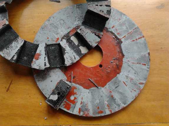
Next day (19th) I cut 12 straps of 1.5" wide by 9"
white polypropylene (PP) strapping, folded the ends, and fed them
through the
12 slots. Then I painted the tops of the magnets, the rotor surface
where the strapping would go, and the strapping. I pressed the
strapping into place and used a flat sheet of UHMW and some small steel
weights to hold it while the epoxy set.
Somehow the whole pace of the project had been less than
stellar - it was taking up the whole month! On the 21st I put the motor
back together. I added a couple of
spacer washers so the extra strapping thickness on the magnets wouldn't
rub on the stator-rotor separator wall. The flux gap ended up at just
over 1/2", which is probably about where it should be anyway. On the
second attempt the shaft still wasn't quite where I wanted it. I ended
up cutting the shaft holding the transmission ring gear 3/4" shorter to
adjust for the motor shaft. Shorter would probably be better anyway.
But another 1/4" would have been too short - it would have run into the
centrifugal clutch drum.
When I hooked it up and tried a test it wouldn't run.
Uh-oh, now what? Later I remembered it needed a jumper across the
ignition switch relay. With that connection the contactor clacked on,
and the motor ran. I'm confident it won't fly apart. The motor
going up to 3000 RPM or more would be more likely to activate the
centrifugal clutch than 2000 RPM. The next day (23rd) I reduced the
batteries to 24 volts. The
control seemed much finer and the motor didn't spin madly as soon as it
came on. That'll be better for testing.
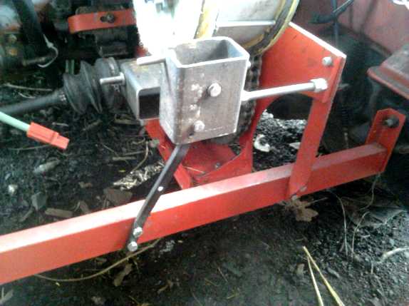
That left one tricky mechanical part to build before an
initial test: the slipping pulley tension rope and tensioner,
controlled with the "gearshift" lever. On the 23rd I figured out a way
that looked like it should work with the rope pull at the top, and set
to making it. That day I made a midway clamp at the bottom, a flat bar
of metal between two bolts, clamping the rope under the bar to the
bottom motor mounting.
On the 25th I suddenly realized that with its helical gear
teeth, the planetary gear would push strongly to one side when there
was pressure on it. In forward all would be fine, but in reverse it
would slide out of the ring gear. It would need to be solidly held, not
just nudged into place by the tensioning rope. I spent that day
mounting a thrust bearing
on the motor shaft to hold it in place.
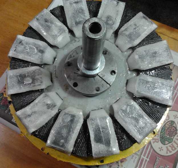
 Pulley/Planetary Gear Assembly Side.
A washer with its inside trimmed to fit holds the bearing ring and
bearing.
On the motor side is a pipe with the motor
end notched to fit the protruding bolts,
and the other end hollowed out
to hold the other bearing ring.
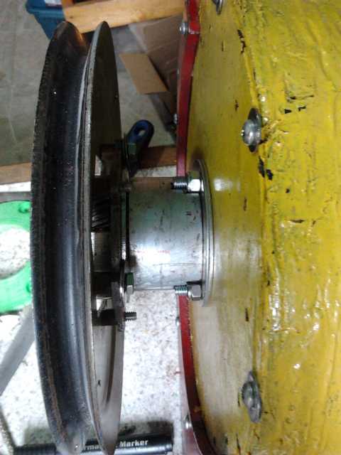
Put together on the motor.
On the 28th I got back to the pulley tensioning mechanism.
I had found a piece of steel that might work as a lever. I cut it and
bent it to the shape I wanted, but
it didn't really look like it would work well and I set it aside.
Instead I beefed up the mounting with a new strut, as the whole
assembly had always been twisting to one side when it tried to drive
the car.
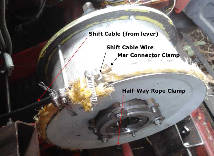
The evening of the next day I came up with what seemed
like a simple, effective new tensioner plan: simply strap the cable
sheath to one end of the rope and the cable to the other with pipe
clamps. When the shift lever was pulled backward and the cable pulled
into the sheath, the two rope ends would be pulled toward each other,
tightening the rope around the pulley as desired. I got some pipe
clamps and put it together the following day [30th], also using a 'mar'
connector's internal clamp piece to make a lump near the end of the
thin cable, to prevent it from slipping through the pipe clamps when
pulled. It seemed to work well, and the car drive was about ready to
test.
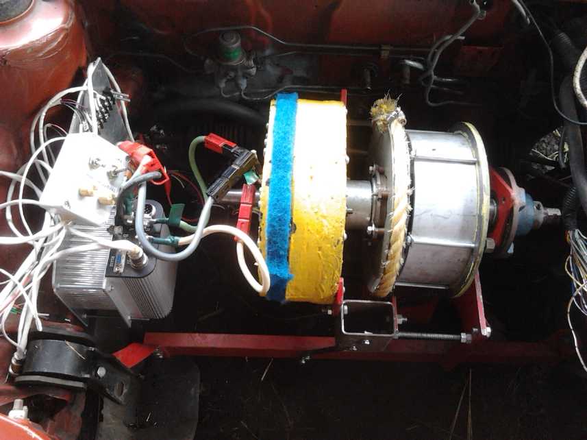 Under the Hood, Left to Right:
Hand-held test control box - Motor controller on heastsink &
aluminum plate -
Connection Wires - Electric Hubcap Motor - Thrust bearing (pipe)
and unseen sun gear on motor shaft -
Tensioner [planets] gear, pulley, rope - centrifugal clutch drum -
unseen planetary ring gear and clutch inner disk on floating shaft -
unseen chain drive to differential - cut-down trailer wheel hub with
its bearings holding the shaft.
I installed the motor and tested it on February 1st. Most
things seemed to work as planned. But, foreseen as a possibility, the
centrifugal clutch didn't engage strongly enough to start the car
moving. It will need some new ideas.
Nickel-Nickel Battery Chemistry Battery Development
Someone pointed me to open cell "nickel foam" available on
alibaba.com . Heretofore I could hardly find a pure nickel product for
sale anywhere, and when I did, the prices were preposterous. (An
exception was finding nickel powder, at MicronMetals.com) I never
thought of looking at the Chinese umbrella vendor group, "alibaba" or
"Aliexpress". There there are a wide variety of manufacturers or
dealers with various pure nickel products at reasonable prices. I found
some that was made for making battery electrodes. It seems the Chinese
want to do business, even if North Americans don't.
Open cell nickel foam should have a large surface area
wetted by the electrolyte, with all the particles well connected to
each other. Nickel powder could be sprinkled into it to further improve
everything, and it could still all be backed with the etched
cupro-nickel sheet metal, for an enormously conductive electrode with a
lot of amp-hours. (This would be the negative electrode, not the
positive that nickel would usually be used for in NiFe or NiMH. In the
alkaline but lower pH environment for NiNi, the positive has to use
graphite materials.)
And it occurred to me that perhaps I could be using that
gum arabic not only as a 'glue' for the powder, but as a barrier to
create a salt bridge between the electrodes, more or less in a dry cell
configuration rather than a flooded cell. That just might solve the
self-discharge problem. (Although, I'm still not sure of the reactions
causing that problem.)
I took the last 'pipe' cell I made apart and painted the
gum onto both sides of a new separator paper. It didn't seem to help.
OTOH, the positrode did a lot of crumbling, it was hard putting it back
together, and I wouldn't swear there was separation with the painted
paper everywhere. Nor would I swear gum arabic is a good substance to
make a salt bridge with to start with. It's soluble. It was just an
idea that could
be tried quickly.
Perhaps agar would be a better thing to try. I fact, agar is
specifically mentioned in the Wikipedia article on salt bridges. And
from that same article, I also got the idea to try another electrolyte.
Perhaps a sulfate salt like potassium sulfate wouldn't give the same
self-discharging effect as potassium chloride? I'm grasping at straws
because I don't know why it's doing it in the first place.
I painted up a separator paper with agar dissolved in hot
water. It jells as it's cooled, well above room temperature. I set that
aside to dry... and apparently set the whole project aside for the
entire rest of the month. I didn't even get the nickel foam ordered.
Bitcoin Miners
Another project I did some work on was the bitcoin miners.
"Mining bitcoins" means getting a reward in bitcoin for using special
computers to improve the operation and security of the bitcoin
blockchain.
I had ordered one in fall 2013, a "Butterfly Labs"
"Monarch". Instead of "installing" it in a computer, it simply
connected by USB. I had a "Raspberry Pi" single board computer that I
heard one could run them on.
(I had also ordered another "Babyjet" miner weeks
previously, but "Hashfast" went out of business without delivering it.
Vindictive customers sued it out of existence because of late delivery
-- even after they had at last delivered the first batch and were at
last ready to ship the rest. Only the lawyers will get anything. It was
a good thing I decided to order the Monarch as well.)
Because of the delays, Butterfly Labs sent 3 miners
instead(!), finally delivered in February 2015. It all comes of
ordering things that are still being designed. The price was greatly
reduced and I ordered two more. The only trouble then was, I couldn't
get them to work.
Finally in the summer I got a linux programming and
bitcoin guru to get them going. He found all the right parts and got it
to work for him. Things still didn't go well for me. I had to replace
the "RasPi" with a "RasPi B+". Twice I bought 5 power supplies that
weren't right and had to take or send them back, the "quality" powered
USB hub I bought to connect it all was crap, and the "pre-April 2015"
miners apparently had problems and would crash occasionally. I could
only hook one up to the Pi and have it run at all, and it would quit
working any time after 3 seconds to 3 hours and sit there until the
BFGMiner program was restarted. So by October I could mine with only
one miner, and
only when I was in the room to watch it like a hawk and keep restarting
it. Nearly useless without going 24/7. Butterfly labs tech support
wasn't much help. Messages went back and forth for 2 weeks with
questions and misunderstandings from him about things I had carefully
stated in my very first message.
By this time it was mid October. When too many bitcoins
are created in a two week period, the "mining" difficulty increases to
compensate. The mining difficulty was "60.9G". (whatever that figure
means.)
Finally in mid December I went into the "BFG Miner"
program code
myself. The usual error message was "Received unexpected queue result
response." I eventually located this phrase in one of the many files,
and since it never recovered from it, I changed it from printing that
to simply restarting the miner program. Then in all but fairly rare
cases with other errors (less than once a day), no matter how often it
boinked, it simply started over and continued 'mining'.
Near the end of December I ordered a new "Raspberry Pi 2
B". I thought I might need one for each miner and an ethernet router to
handle them all, but the new one had a quad core ARM processor running
over double the clock speed of the originals. To my amazement, I simply
unplugged the micro-SD card with all the hard-won software from the old
one and plugged it into the new one, and it worked. It booted much
faster, and with two miners attached, it all ran much longer without
stopping. Then I hooked up 4 (at two electric separate outlets on
different circuit breakers - 1820 watts). (With 4 it rarely runs half
an hour before stopping and restarting. So what?)
But by this time the mining difficulty had gone to 104G,
and before the end of January it hit 120G - double the October figure,
and hence 1/2 the rewards. Each 2 weeks I watched the "income" reading
from the
miner or miners drop. If I had got all five running last spring, I'd
have made hundreds of dollars a month. As it is, these power-hungry
beasts consume most or all of the income in hydro bills.
As
a mere handful of the biggest banks move in with tens of thousands of
bitcoin miner machines, probably set up wherever power is cheapest,
they have reduced the rewards more and more for the thousands of common
'private
miners' like me. (...and the many more former or would-be private
miners with now outdated mining equipment - or who perhaps never got
theirs running? The 4 biggest outfits - financial institutions of
some sort I presume - account for about 1/2 the total mining of the
pool with 20 quadrillion hashes per second out of 40.)
And so much time went by before I got it all running
because I always had other things to do -- especially, renewable energy
projects. And none of this is really long-term since all bitcoin mining
ends in 2022 IIRC, or sometime around then.
But if I use the miners in place of electric heaters that
would be running anyway, the bitcoin rewards pay (or almost pay) for
the power, and hence I can get "free" (tho rather noisy with the strong
fans) electric heat. (And you thought there was no "green energy'
connection!) Of course it doesn't generate or save any energy overall,
but with the bitcoin income applied against the electric bill, they'll
still eventually pay for the miners and equipment. On the 13th I found
some 15' long USB
cables so I could start spreading the miners around the house. (The guy
at London Drugs said 15' was about the limit for USB 2. Maybe another
USB hub can extend the range to reach the far rooms?) Then I can work
out
some mufflers for the noise. The other saving grace will be to get the
lambda ray converter making the electricity if I can manage that.
Needing 2420 watts continuously (if all 5 miners are running) is good
incentive! Then however slowly the income is generated, it's all income.
Otherwise, if I'm lucky, either the big banks will go out
of business
(seemingly inevitable) and their tens of thousands of miners will be
turned off or destroyed (hmm) and the mining difficulty will drop in
half, or the price of bitcoins will keep rising (pretty likely) and
they'll remain at least somewhat profitable as one gets less and less
coin. Or both.
Using the miners as hot water preheaters,
maybe isn't too far fetched either. The miners run at around
60°C according to their own internal temperature sensors. This is
inaccessible, but I measured the temperature of the air coming out of
the fans: about 37°C, from all 4 miners. (The following days, with
the house a little cooler because with the bitcoin miners running I
didn't bother to light the woodstove, they were all about 35°.) If
water could be raised to near that temperature, raised say from 10°
to 33°, it would be half way to the 55° I usually have my hot
water set at. If one put a copper water tank inside a fairly close
fitting box or tube with the warm air blowing in one end, it would
gradually get up to that temperature. That tank would then feed the
regular water tank - the usual arrangement for solar hot water, but
with no outdoor plumbing potentially subject to freezing. The warm air,
cooled as it flows through the box to the far end if the water is cold,
then comes out into the room to heat the room. If the air is often
coming out markedly cool, two or three miners could be used to provide
more heat. The water heater elements as well as electric space heaters
"waste electricity" by not producing any bitcoin, and this would cut
their 'on' time way down.
In Passing
(Miscellaneous topics, editorial comments & opinionated rants)
Rising Sea Levels
People talk of global warming. For quite a while I wasn't
convinced, and plenty of people still think it's a myth. Recently there
have been alarming documentaries on melting glaciers and melting
permafrost. It looks to me like the warming timeline has been
drastically speeded up by geoengineering.
Now the effects are becoming
definitely evident. Not only are trees budding here in January instead
of
February or March, but ocean levels definitely appear to be rising.
Once about 15 years ago, an El Niño plus torrential rain on the
mainland causing the Fraser river to flow a deluge into the strait,
plus a high tide but with no large waves, caused the harbor to reach
the
lowest areas of the concrete sea walk level and deposit ocean debris on
it. This was a unique event until this winter.
This winter the water has seemed surprisingly close to the
lowest walk levels on a number of occasions when I was there, and
several times has reached it - I saw ocean debris deposited on it. Once
I had to wait for a low ebb between small waves and run across a
certain spot. I have never seen the water way up there before, and it
was only 6" lower the next time I went to that location.
By itself this could indicate the land around Victoria BC
is sinking. But we now frequently hear in the news (at least on
Youtube) of record flooding during storms in coastal areas in various
places, indicating it's a global phenomenon -- the rising sea levels
that are only to be expected from melting of glaciers in Greenland,
Iceland, the Rockies, Andes and Alps mountains, not to mention at the
poles. What havoc
will a ten foot rise wreak around the world? What will happen in
crowded Bangladesh where I hear 100 miles inland the elevation is still
just 10' above sea level? Where will all those people go?
Rising Bank Dangers
People have been warning that the global banking system
must fail for some years now, and that the banks as whole are all
linked together and overall, insolvent. Few cracks are visible on the
surface. Precious metal prices have been suppressed, and stock markets
have been propped up, probably with a trillion dollars of artificial
stock buying by government agencies. But now commodity prices are also
falling as monetary liquidity dries up through the whole economy. Some
predicted this "deflationary debt collapse" (to be followed by
hyperinflation), for example Mike Maloney ("Hidden Secrets of Money"
video series) and Harry Dent, who points out how demographics of aging
populations aren't going to consume like young families.
Now we're starting to see how this might play out with the
banks: "non-performing loans". There are trillions and trillions of
dollars worth of foreclosed mortgages (with falling house prices and no
buyers), defaulted car loans, defaulting credit card debt, unpayable
student loans (no jobs for grads), and defaulting corporate debt as
companies downsize and go out of business, as they are doing across the
board - their ex-employees swelling the ranks of the unemployed. Even
Wallmart is closing around 260 stores, 150 in the USA. Global shipping
(the "Baltic Dry Index") is hitting record lows of cargo tonnage, which
is being matched by rail and truck freight traffic on land. A large
shipping company spokesman said in January they didn't have one ship at
sea in the Atlantic. They were all sitting in ports waiting for enough
cargo to bother sailing.
Notably, upcoming bankruptcies will include most all the
"fracking" companies, to whom the banks loaned a trillion dollars when
oil prices were far higher. These were never viable overall to start
with, and now even the best producing "established wells" operate at
huge losses, and cheap Iranian oil is just coming on line to drive the
price down further. The Alberta tarsands is in the same position.
If the governments print money to bail out the banks,
hyperinflation will come. Otherwise a "bank holiday" one fine weekend
(they may blame "a technical glitch") followed by the "bail-ins"
(exchange of depositors' money for worthless bank stock) and "capital
controls" (can only take out your money a bit at a time) surely has to
be in the works.
There is now a chorus of voices rising from the swamp like
frogs croaking, saying "Get your money out of the banks!" There are
many good suggestions for converting it into real goods and precious
metals and for keeping a good chunk of cash well hidden.
You could also transfer money to your PayPal account (or
perhaps even to an account on a bitcoin exchange - with or without
buying bitcoin?), institutions which hold your funds electronically but
which aren't banks -- they don't lend out or invest your money and so
have no "non-performing loans" or "derivatives" where your savings are
being lost. So they should survive a banking system collapse.
Newsletters Index/Highlights: http://www.TurquoiseEnergy.com/news/index.html
Construction Manuals and information:
- Electric Hubcap Family Motors - Turquoise Motor Controllers
- Preliminary Ni-Mn, Ni-Ni Battery Making book
Products Catalog
(Will accept BITCOIN digital currency)
...all at: http://www.TurquoiseEnergy.com/
(orders: e-mail craig@saers.com)
Daily
Log
(time accounting, mainly for CRA - SR & ED assessment purposes)
January 1-3: Writing previous newsletter
4: Enquired about "nickel foam" for battery electrodes to
Chinese/Alibaba.com supplier.
5: Tried "gum arabic" as a salt bridge in Ni-Ni battery. It didn't seem
to help.
8: Make Hubcap Motor Magnet Jig: Tried to transfer G-Code spreadsheet
data from Netbook to new Tablet - had to buy cable.
9: Couldn't find a spreadsheet program that would run on the Tablet!
10: Did spreadsheet on the netbook. Made up G-Code program on CNC
machine computer. A number was a bit off and the magnets didn't quite
fit.
11: Bought more plastic and made 2nd one.
12: Made top piece for it.
13: Made template piece to help place milled slots.
14: Ripped failed Hubcap Motor rotor apart. (Found rotor failure was
due to zinc anti-rust spray paint on rotor.)
15: Milled slots in "spare" motor rotor (motor to be used in Variable
Transmission/Sprint car tests).
19: Epoxied the strapping to the rotor magnets.
21: Assembled the motor
22: Adjusted (cut) transmission shaft length to match motor shaft, and
mounted motor in Sprint. Tested motor - ran great!
23: Figured out plan for tension rope attachment and operation. Made
center clamp for rope at bottom of control/tension pulley.
24:
25: Made thrust bearing mounting system to prevent tension
pulley/planet gear assembly from pressing sideways.
26: Worked on "Hands-On Democracy - How to run a world" text.
27:
28: Made support strut for motor/transmission housing to prevent it
from twisting under load.
29: Figured out that pipe clamps and the wire clamp from inside a mar
connector could be used to hold the activation cable to the tensioning
rope and pull it tight from the gear shift lever.
30: Bought pipe clamps and made/installed the linkage. It seemed to
work well but I had paperwork to do for Canada Revenue before they
fined me another 100$ for late submission, so I at last set about that
instead of installing the motor and testing the completed car drive.
31:
Feb 1: Installed motor in Sprint and tested operation.
Feb 2: Working on this newsletter.
Electric Hubcap Motor Systems - Electric Transport
Electric Hubcap motor, Chevy
Sprint & Variable Transmission
I really wanted to get this project, this unfinished
business, going
again. I really do want the "ultra-efficient" car. Development of the
new motors and controllers is dragging on, and theoretically I already
had the required components for this. With a new motor rotor I could
reassemble
the motor and get back to
the rest. But I decided I didn't want to just use the other similar
rotor, potentially subject to the same problems. Much of my trouble has
come from not building things robustly enough. In the last issue I
mentioned some ideas for improving the
rotors.
I thought maybe this was something I could get someone at
AGO to do
if I had cash. I had the CNC drill-router to make a plastic piece with
magnet holes in it, but rather than do it all manually on a spreadsheet
again, perhaps someone could pick out a proper CAD program like the
"Rhino Express" that Victoria Waterjet uses, and figure out how to
apply it to my machine. Then it would be almost trivial, like at
Victoria Waterjet. Then a "DXF to G-Code" converter that made
compatible G-Code would still be needed... or a G-Code program that
would work with my router, bypassing my present software entirely.
It has occurred to me more than once that a solid lip on
the outside
of the rotor that the magnets would butt solidly against would be a
great asset. To my mind, the biggest advantage of the outer drum rotor
motor type, with the coils inside, is that the magnets are pressed
against the inside of the drum when spinning. The RPM could be very
high before the magnets would start coming loose, and even if loose,
they could hardly fly off. But to put a lip on a disk rotor seemed
pretty tricky. A fatter disk could be milled on a lathe, but that would
be an awful lot of milling. And the steel, "shorting" the outside of
the
magnetic circuit, would interfere (if only a little) with the magnetic
field. Welding a non-magnetic stainless steel ring around the outside
might be the most practical. At least 3/16" thick? and as wide as the
magnet thickness - but then it would need slots or holes
between the magnets for centrifugal air fan flow. Better still... no
holes
in the rim ring: drill them through the rotor disk itself, between
magnets out near the rim. (Yes, I think I like this. But it would be
quite a project with my meager welding skills and no curve bender. Hmm!
I could probably find 3/16" x 3/4" S/S bar... and use the steel roller
at Makerspace to bend it into a ring. So I should actually be able to
make a good ring. Then use lots of weld and grind it smooth later. Hmm!
More robust! How bad do I want to build that?)
As usual, having given the project thought and with no one
else
around, I started in on it myself. I decided to do it with the PP
strapping wrapped through slots in the rotor after all. My mind spaced
out on the fact that by gluing the magnets on I was committing to doing
one layout, NNSSNNSSNNSS or NSNSNSNSNSNS. I couldn't easily change it
later. I decided on the former since the Kelly BLCD motor controller
still looks
like the best bet for now.
 I thought I'd
just make a magnet placement jig using the
usual
spreadsheet for the G-Code, but I'd try doing it on my new RCA Android
tablet - No annoying fan or drive whirring away as you work! First
finding an adapter to hook up a USB memory stick having a template
spreadsheet on it took a day. Then another couple of days passed before
I found that I couldn't find a spreadsheet program that worked.
I thought I'd
just make a magnet placement jig using the
usual
spreadsheet for the G-Code, but I'd try doing it on my new RCA Android
tablet - No annoying fan or drive whirring away as you work! First
finding an adapter to hook up a USB memory stick having a template
spreadsheet on it took a day. Then another couple of days passed before
I found that I couldn't find a spreadsheet program that worked.
So! Another couple of hours on the old netbook (sines and
cosines on
the spreadsheet) and on the drill-router's computer (final G-Code file)
got the program done. But I had a mistake, one number I got wrong in
the spreadsheet but close enough that I didn't notice it on the screen
image. The magnets didn't quite fit in some of the slots. The next day
I looked for more plastic. I had been 'lucky' enough to find one piece
stashed away, and had now ruined it. Instead of getting UHMW at
Industrial Plastics, I found some kitchen cutting boards that were the
same stuff but doubtless cheaper. (Retail plastic is cheaper than
"industrial supply" in Victoria!?!) I cut the main piece that day and
the cover piece the next. Let's see... Friday, Saturday, Sunday,
Monday, Tuesday. For one lousy magnet jig! Somehow, I just had to pick
up the pace!
The next step was to
mill slots in the rotor for the magnet holding straps. Then I realized
I could have also cut slots in the jig to mark off in crayon or felt
pen where to mill the slots in the rotor where the straps go through
it. Rats! I decided to make another jig/template for that purpose. The
more uniform everything is, the better balanced the rotor will be. If
it's well balanced and the magnets strongly attached, perhaps it can
withstand 4000 RPM or more and be "rated" for 3000 in regular operation
instead of
the 2000 RPM max figure I've been working with. That would give the
motors more
flexibility.
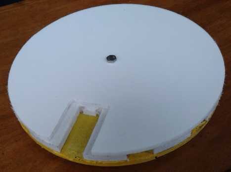
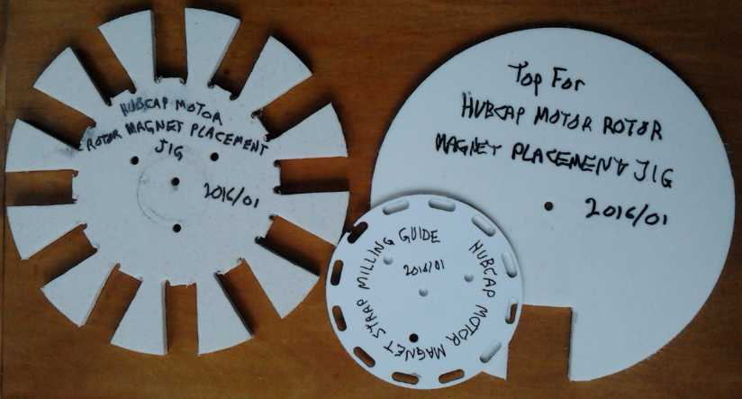
Anyway I made it in 1/8" plastic instead of 1/2", which is
easier to
get a felt pen into to trace out the slots. I'd have liked to have the
slots 1.5" wide for 1.5" wide strapping, but that would cut a complete
circle around the rotor, breaking it into two pieces. I made them about
3/4". The strapping would just have to fold through them. (That worked
out well - better.) I designed and made the template on the morning of
the 13th, so at least the pace was improving.
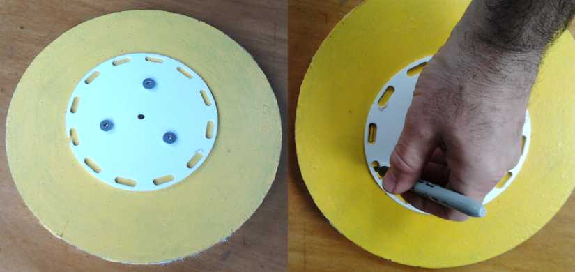 The slot template
 But when at
last I went to rip the broken rotor apart (14th) and
recover the magnets from it, I found there was a good reason it had
come apart. I thought the epoxy was pasted on the plain steel disk, but
I discovered the disk had been given a spray-on zinc anti-rust coating.
I had previously discovered on the first Electric Caik motor that that
spray-on zinc coating was feeble and would rip apart across its whole
surface as soon as the motor hit any decent RPM. This rotor had been
made just before the first Electric Caik. Somehow it had lasted until I
tried it with no load with the Kelly controller, which had spun it up
to high RPM.s almost instantly.
But when at
last I went to rip the broken rotor apart (14th) and
recover the magnets from it, I found there was a good reason it had
come apart. I thought the epoxy was pasted on the plain steel disk, but
I discovered the disk had been given a spray-on zinc anti-rust coating.
I had previously discovered on the first Electric Caik motor that that
spray-on zinc coating was feeble and would rip apart across its whole
surface as soon as the motor hit any decent RPM. This rotor had been
made just before the first Electric Caik. Somehow it had lasted until I
tried it with no load with the Kelly controller, which had spun it up
to high RPM.s almost instantly.
Without meaning to take away from the force of everything
above
about improving the rotors, this put a different complexion on things.
Without the spray-on zinc coating, the rotors were doubtless much more
robust than I had been giving them credit for. The other rotor was the
one with a zinc coating done at Victoria Powder Coating. I couldn't
think of a way to test it except the same way as the previous rotor,
but it had an entirely different feel and it seemed likely that it was
much stronger. I decided to "upgrade" it and use it. Forget the outer
rim. I would sand the existing strapping to thin and even it, and to
roughen the surface. Then I'd mill the magnet strapping slots
(notwithstanding that the magnets would make everything harder to do),
and add the "round the magnet" strapping as a second layer. That will
(a) use up the 'spare' rotor, and (b) save me from making another rotor
in
the NNSSNNSSNNSS configuration that I expect won't be wanted again -
assuming I get the unipolar controller working well.
I looked somewhat dubiously at the rotor with its slightly
crooked,
unevenly spaced magnets. Now it looks amateurish. The new jig would
have fit them on perfectly. But it would do. Assuming the powder coated
zinc is strong (unlike the spray paint) and I can get it balanced, this
rotor should surely do the 4000+ RPM and run fine at 3000. If it
isn't, magnets will break off and I'll end up ripping it all apart,
sanding the remaining coating off, and redoing it all. (So far all is
fine, after some run-ups and other trials with the Kelly controller.)
But how to do the milling? If the magnets faced down, the
rotor
would clamp onto the carriage really hard. It would be hard to move and
remove not to mention dangerous, yet couldn't be trusted not to shift
while milling. If they were up, it had better be well clamped when the
bit and chuck came near, yet the magnets would grab everything that
came near including the clamping piece. I finally hit on the idea of
using a stiff board just a little longer than the rotor diameter, with
a hole at each end to bolt it down with stainless steel screws. Ideally
I'd want the rotor to turn on its center to get each slot exactly
aligned. The board and eyeballing it will do. By this time it was late
afternoon and I had an evening engagement. Well, mañana!
 Next, would I
just have to put up with painstakingly
pulling the
shards from the magnets afterward, or could I fit something into the
narrow spaces that I could pull off later, along with the shards? Tape?
How about duct seal or modeling clay?
Next, would I
just have to put up with painstakingly
pulling the
shards from the magnets afterward, or could I fit something into the
narrow spaces that I could pull off later, along with the shards? Tape?
How about duct seal or modeling clay?
On the afternoon of the 15th I drilled holes in a dogwood
2x2" for a
clamp, clamped the rotor onto the milling machine, and started. My 1/8"
milling bit soon snapped (oops!), and I went to shop for another one.
It was too late in the afternoon and the road to KMS Tools was blocked
with daily traffic. I tried a couple of nearby 'hardware' stores to no
avail,
and Western Equipment didn't have any 1/8". Finally I hit AGO on my way
home. "Why so tiny?" asked the machinist. Okay, if he considered that
tiny, maybe I should go bigger? "How about 3/16"?" He gave me one. I
went home and got 3 slots milled before dinner. The other 9 took up the
rest of the evening. I sharpened it a couple of times. There's nothing
fast about milling steel, even mild steel. And in spite of the
template, the slot placements and lengths weren't even. This was
probably inevitable since the placement of the magnets they were
supposed to line up with weren't the best to start with. Of course if
more of these motors are to be produced, the magnets will be aligned
with the new jig, and the slots will be cut by CNC abrasive waterjet
along with the other rotor disk features. Hopefully this is a one-off,
tho I have a couple more slotless rotors left if I do make more BLDC
type motors.
I used duct seal pasted against the magnets to try to
capture the
shavings,
but it was only partly effective and there were plenty left. I tried
blowing them off with compressed air, to no avail. Trying to pick them
off by hand led inevitably to tiny, sharp steel slivers.
I didn't get at it on the weekend. On Monday (18th) I
got out
another supermagnet and held it with vise-grips, and stuck a thin round
file to that magnet, also holding the file with my hand, with the
smooth and pointed grip end sticking out. (A very long nail might have
worked just as well.) I put a leather glove on my other hand. Whereas
two supermagnets clamped strongly together, it was pretty easy to pull
the long, thin file away from the rotor magnets. But some of the
filings on each rotor magnet stuck to the file as I touched it then
pulled it away, because it was being supplied with magnetism by the
supermagnet in the vise-grips. And charge tends to collect at a point,
like the end of the file and even the round side. Then I ran my gloved
fingers down the file,
pushing the shavings off the end and dropping them into the garbage
bucket. After quite a while of this rather tedious procedure the rotor
looked much cleaner. I sanded the tops of the magnets (wooden sanding
block) to remove any projections and roughen the surface, and called it
"good enough".
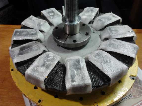
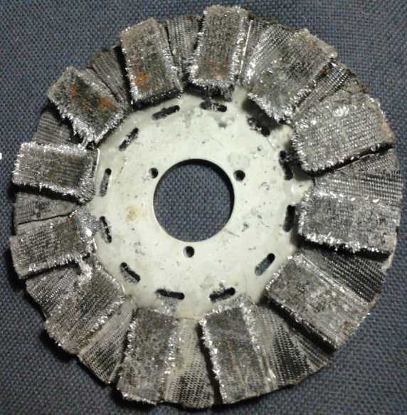
 Next day
(19th) I cut 12 straps of 1.5" wide by 9"
white polypropylene
(PP) strapping, folded the ends, and fed them through the 12 slots. The
ends overlap behind, making them a double thickness over most of their
length on the back of the rotor.
Then I prepared a flat surface and put a sheet of polyethylene (PE) on
it so the epoxy wouldn't stick. I mixed about 70g of epoxy and used a
1" brush to paint the tops of the magnets and the strapping from the
inside. (It was barely enough epoxy.) Then the outside over the
magnets. After it was all on I turned the
rotor over so the magnets were down and pressed against the PE on the
flat surface - so nothing extra would stick out from the flat tops of
the magnets. Then I painted the rotor disk back and the rest of the
straps and pulled both ends tight and stuck them down. Then a small
piece of PE and a small steel weight went over each one to hold it
while the epoxy set. That wouldn't hold the PP stretched, but will
avoid
protruding ends and I trust hold well enough to ensure the magnets
never come loose. When it was mostly set, I turned over the rotor and
found there were "bubbles", disconnects, between the magnets and the
strapping in many places. I pulled the weights and PE bits off the back
and put them on the magnets. It wasn't easy to get them to stay in
place on top of each magnet, as they wanted to slide magnetically
across the still slightly gooey epoxy to join adjacent magnets of
opposite polarity. I ended up breaking up some styrene foam pieces to
hold them apart. If it wasn't for the strong magnetic press on the
steel weights, I'd have worried that the epoxy was too much set to join
up. As it was I was sure they would be well bonded. Actually the
picture shows from the lack of solid black shadows that there were
still air bubbles. But it seemed good enough.
Next day
(19th) I cut 12 straps of 1.5" wide by 9"
white polypropylene
(PP) strapping, folded the ends, and fed them through the 12 slots. The
ends overlap behind, making them a double thickness over most of their
length on the back of the rotor.
Then I prepared a flat surface and put a sheet of polyethylene (PE) on
it so the epoxy wouldn't stick. I mixed about 70g of epoxy and used a
1" brush to paint the tops of the magnets and the strapping from the
inside. (It was barely enough epoxy.) Then the outside over the
magnets. After it was all on I turned the
rotor over so the magnets were down and pressed against the PE on the
flat surface - so nothing extra would stick out from the flat tops of
the magnets. Then I painted the rotor disk back and the rest of the
straps and pulled both ends tight and stuck them down. Then a small
piece of PE and a small steel weight went over each one to hold it
while the epoxy set. That wouldn't hold the PP stretched, but will
avoid
protruding ends and I trust hold well enough to ensure the magnets
never come loose. When it was mostly set, I turned over the rotor and
found there were "bubbles", disconnects, between the magnets and the
strapping in many places. I pulled the weights and PE bits off the back
and put them on the magnets. It wasn't easy to get them to stay in
place on top of each magnet, as they wanted to slide magnetically
across the still slightly gooey epoxy to join adjacent magnets of
opposite polarity. I ended up breaking up some styrene foam pieces to
hold them apart. If it wasn't for the strong magnetic press on the
steel weights, I'd have worried that the epoxy was too much set to join
up. As it was I was sure they would be well bonded. Actually the
picture shows from the lack of solid black shadows that there were
still air bubbles. But it seemed good enough.
Somehow after making the mostly unneeded jig and template,
just
doing the rotor milling and strapping took another whole week. So much
for "picking up the pace!"
On the 21st I put the motor back together. While it was
still apart I
noticed that the gear on the end wasn't straight, in spite of having
been pressed on endwise with the hydraulic press. There were other
problems: the gear meant the rotor end bearing (needle bearing with
pressed mounting) had to be put on from the far end. That also meant
putting on the rotor end cover first instead of last, and it was in the
way of seeing and adjusting the placement of the rotor onto the shaft.
Instead of a nut driver, an open end wrench had to be snuck in from
the side and the SDS taper-lock bushing bolts tightened a bit at a
time. I added a couple of spacer washers so the extra strapping
thickness on the magnets wouldn't rub on the stator-rotor separator
wall. The flux gap ended up at about 17/32", which is probably about
where it should be anyway. On the second attempt the shaft still wasn't
quite where I wanted it, but I decided it was close enough and some
spacer washers could be added when mounting the motor onto the
transmission. I didn't work continually all day, having other things to
do as usual, but it was late when I finally had the motor together. The
extra rotor diameter of the wrap-around strapping lightly rubbed on the
body, making some noise, but not hard enough to affect operation.
 On the 22nd I checked the motor fit, and decided that
spacers would
be too much. There were already nuts making 3/8" extra space. Another
set would be 3/4". The bolts just might bend. But there seemed to be a
simple answer. It looked like I could just cut the shaft holding the
ring gear 3/4" shorter. Shorter would probably be better anyway. The
ring gear was well pressed onto the splined shaft, but I eventually
wedged it off, cut the
shaft down, and pounded the gear back on. It was almost too much: the
pulley for the tension rope rubbed slightly on the clutch drum. Another
1/4" would definitely have been too much. But the motor now fit on with
no 'extra'
spacers, just a couple of washers to help align the shafts.
On the 22nd I checked the motor fit, and decided that
spacers would
be too much. There were already nuts making 3/8" extra space. Another
set would be 3/4". The bolts just might bend. But there seemed to be a
simple answer. It looked like I could just cut the shaft holding the
ring gear 3/4" shorter. Shorter would probably be better anyway. The
ring gear was well pressed onto the splined shaft, but I eventually
wedged it off, cut the
shaft down, and pounded the gear back on. It was almost too much: the
pulley for the tension rope rubbed slightly on the clutch drum. Another
1/4" would definitely have been too much. But the motor now fit on with
no 'extra'
spacers, just a couple of washers to help align the shafts.
Then I hooked it up and tried a test run. It wouldn't run.
It didn't
try to turn and seemed dead. I was frustrated for the zillionth time
that I couldn't see if the rotor position sensors were working, and I
decided to at last make a "break-out board" to insert in the cable,
with 3 LED.s that would tell the state of the 3 sensors. I closed up
the car for the day.
But hmm... the Kelly controller came on and the steady
green light
meant "all okay". It would have been blinking if the sensor state was
wrong (all sensors off or all on). Then, come to think of it, I hadn't
heard
the contactor click on, so of course there was no power to the
controller power circuits or the motor. I opened the car and removed
the hood again. I put a jumper across the ignition switch relay and the
contactor clacked on. I tried again and the motor ran. I'm pretty
confident it won't fly apart. Hopefully the whole mechanism would turn
fast enough to activate the centrifugal clutch. I can (I'm sure) now
run the motor up to 3000 RPM or higher in order to make that happen.
The next day (23rd) I reduced the batteries to 24 volts. The control
seemed much better and the motor didn't spin madly as soon as it came
on. That'd be better for testing.
That left one tricky mechanical part to build before an
initial
test: the slipping pulley tension rope and tensioner, controlled with
the "gearshift" lever. I recall from 2012 that it was best to fasten
the rope on one side of the pulley and have the lever pull on both ends
of the rope on the opposite side of the pulley, making a relatively
balanced pull, instead of yanking the pulley and planet gear assembly
towards one side by having the rope loop around the whole pulley,
anchored and pulled from almost the same place. (Balanced should also
make forward and reverse tensioning even, and half loops should have
much less tendency to grip the pulley by friction even without tension
on the rope.)
 On the 23rd I looked it over and came up with a better
plan than I'd
had. If the midway point was near the bottom instead of the front, the
tension cable attachment would be near the top - which was already
where the cable would sit if lifted a bit. The only tricky part then
would be attaching a stationary anchor/mounting point. It would be a
bit distant from potential anchor points on the frame. Oh well, one can
always bend up some piece of metal to fit somehow.
On the 23rd I looked it over and came up with a better
plan than I'd
had. If the midway point was near the bottom instead of the front, the
tension cable attachment would be near the top - which was already
where the cable would sit if lifted a bit. The only tricky part then
would be attaching a stationary anchor/mounting point. It would be a
bit distant from potential anchor points on the frame. Oh well, one can
always bend up some piece of metal to fit somehow.
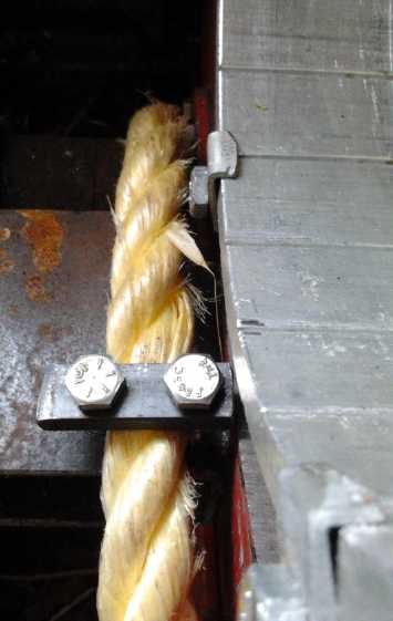
I concentrated that day on the midway clamp at the bottom.
Access
was okay once I took the motor off again. The only thing there seemed
to be enough room all around for was a flat bar of metal between two
bolts, clamping the bar to the bottom motor mounting. After making the
bar with two bolt holes, I drilled and threaded one bolt hole on the
motor mount, then used the bar with a bolt into that hole to locate the
second hole. (Then as I expected, the tension pulley hit the bolt heads
until
the rope was tightened down.)
 Now, just how was all this going to connect and
work?
Now, just how was all this going to connect and
work?
The tensioning pulley and planetary assembly were free to
pull out,
to move sideways toward the motor. In 2012 I had had a needle bearing
between
the motor and the pulley to prevent that, but it couldn't be slid onto
the motor shaft now that the sun gear was pressed onto it. I had
thought that, forces being balanced, the tensioning rope on the pulley
would keep it from sliding out.
On the morning of the 25th I woke up
with the realization that because the gears were helical, the forces
weren't balanced. There would be a strong push to the side when the car
was being pushed. In forward the push simply forces the planetary gear
assembly against the ring gear, but in reverse it would push it out
toward the motor. It definitely would need something to prevent that,
preferably a thrust bearing, and the thrust bearing would need some
sort of mounting.
I tackled the problem that day. I removed the green
plastic piece that had centered the pulley on the motor shaft with the
needle bearing. I had large thrust
bearings I'd purchased
for the reluctance motors. I couldn't quite think how to do the pipe,
and I went to the mechanic at AGO. He made a suggestion. I left
thinking I pretty much knew what to do. After I
started lathe-milling a stand-off pipe, it occurred to me that the pipe
should
only hold one side ring. That was a little different than the
suggestion, but it would allow play in case the shafts weren't
perfectly aligned. I had just started
cutting deeper but stopped when it dawned on me that it was already
just how
it should be. The thrust bearing and the other side ring should be in a
recess
on the side of the planet assembly. The one thing that would be needed
for this arrangement would be for the
motor to stay in constant good contact. Otherwise the bearing pieces
would fall out
and hang on the motor shaft, as there was nothing else to hold them in.
I assumed I could get it.
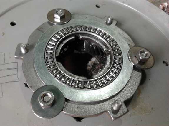
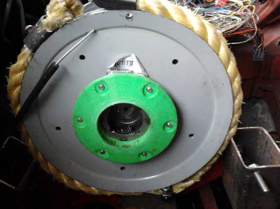
Pulley/Planetary Gear Assembly Side.
A big washer with its inside trimmed to fit the bearing and its
side ring, is held in centered position by small washers and nuts.
(Small washers with one side filed to exact fit are under the larger
washers and nuts.)
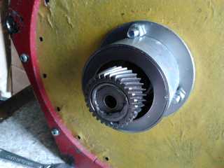
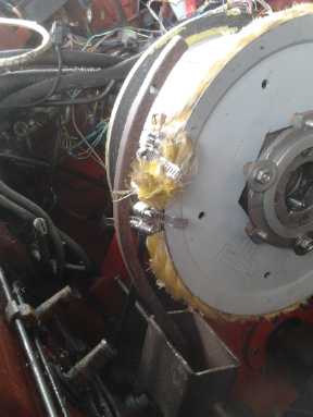
On the motor side is a pipe with the motor end notched to fit around
the protruding bolts,
and the outer end is grooved out to hold the other bearing side ring.
Put together on the motor.
 On the 28th I got back to the pulley tensioning mechanism.
I had found a piece of steel that might work as a lever. (but it was a
bit on the light side.) I cut it and bent it to the shape I wanted, but
it didn't really look like it would work. The way it would pull would
tighten one rope and loosen the other. It seemed to need a stationary
piece to pivot from, and there wasn't anything stationary up near the
top of the mechanism. I thought of a few ideas, but wasn't satisfied
I had a winner.
On the 28th I got back to the pulley tensioning mechanism.
I had found a piece of steel that might work as a lever. (but it was a
bit on the light side.) I cut it and bent it to the shape I wanted, but
it didn't really look like it would work. The way it would pull would
tighten one rope and loosen the other. It seemed to need a stationary
piece to pivot from, and there wasn't anything stationary up near the
top of the mechanism. I thought of a few ideas, but wasn't satisfied
I had a winner.
 Occasionally I
remembered that the whole transmission
mechanism would twist badly when it tried to move the car. Lacking
inspiration on the other, I decided to tackle this and put in a
diagonal brace piece. I found a 10" piece of steel for it. As usual
everything is harder than expected. The
cordless drill wouldn't fit inside the hood to drill the bolt holes,
and I ended
up removing both mounting pieces and taking them into the shop to do on
the
drill press. As soon as I finished, there was a torrential deluge and I
put the hood on and went inside. Considering it could have been cold
and snowing much of the month, I'll count my blessings that this year's
mostly warm January
weather has only occasionally delayed the work.
Occasionally I
remembered that the whole transmission
mechanism would twist badly when it tried to move the car. Lacking
inspiration on the other, I decided to tackle this and put in a
diagonal brace piece. I found a 10" piece of steel for it. As usual
everything is harder than expected. The
cordless drill wouldn't fit inside the hood to drill the bolt holes,
and I ended
up removing both mounting pieces and taking them into the shop to do on
the
drill press. As soon as I finished, there was a torrential deluge and I
put the hood on and went inside. Considering it could have been cold
and snowing much of the month, I'll count my blessings that this year's
mostly warm January
weather has only occasionally delayed the work.
 The following
evening (29th) I had the idea
that the
shift/tensioning cable could simply be clamped to the rope with pipe
clamps, and that if their heads faced up, outwards, the tightened
clamps
wouldn't even protrude beyond the ouside of the rope. That would be way
simpler than anything else I had thought of!
The following
evening (29th) I had the idea
that the
shift/tensioning cable could simply be clamped to the rope with pipe
clamps, and that if their heads faced up, outwards, the tightened
clamps
wouldn't even protrude beyond the ouside of the rope. That would be way
simpler than anything else I had thought of!
In the morning I bought some small pipe clamps. There
wasn't much cable sticking out of the end of the sheath - almost none
when the shift lever was pulled back to "Low". I removed it, slid the
wire part way out, and cut the sheath so there was about 3-1/2" when
it was forward in "Park". But what would stop the thin steel
cable from slipping through the pipe clamps and the rope loosen? I had
thought of silver soldering some blob on the end. But the cable had no
rust... was it stainless steel? I've had no luck trying to silver
solder to that. Then I thought of screwing the clamping piece of a mar
wire connector on near the end of the cable. Much easier, and it could
be slid up and down and retightened to adjust, or removed to let the
cable slide out of the sheathing entirely if needed! I had some, so I
got one and screwed it on. I installed the shift lever end of the cable
so the other end would be in the right place, and slid on the pipe
clamps and tightened them in about the right positions.
When the lever was pulled back from "Park" to "Low", the
pulley went from "too loose" to "can't turn by hand". With the rope
backed off to "Reverse" on the lever, pulling up on the link area
seemed to tighten the pulley quite well. A short rope there to pull on
should allow control from under the hood for testing. With that and the
motor in place, the car would at long last be ready for a test. It was
just early afternoon and there should have been enough time, but
somewhere over the years I've lost not the
enthusiasm but much of the excitement for doing the project. There was
an evening
music jam to think of, and I went off to start working on some
paperwork for Revenue Canada that was soon due and I was getting
increasingly anxious about.
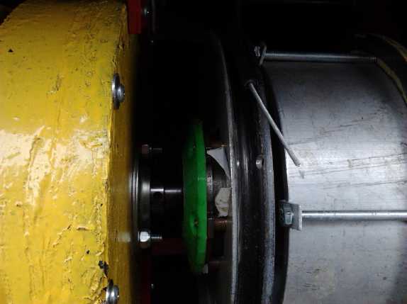
Under the Hood, Left to Right:
Hand-held test control box - Motor controller on heastsink &
aluminum plate -
Connection Wires - Electric Hubcap Motor - Thrust bearing (pipe)
and unseen sun gear on motor shaft -
Tensioner [planets] gear, pulley, rope - centrifugal clutch drum -
unseen planetary ring gear and clutch inner disk on floating shaft -
unseen chain drive to differential - cut-down trailer wheel hub with
its bearings holding the shaft.
I got back to it on Monday February 1st. I put in the
motor and connected it. For some reason it would only run in one
direction, to push the car backward. Usually this would signify crossed
phase wires, but they were marked with colored tape and I connected
them the same as before. The Kelly BLDC motor controller started
blinking its red LED twice. I decided backward was good enough for the
initial test, and shrugged it off.
Rather than a pull rope, I reached into the car and simply
set the tension (ex 'shift') lever to a moderate tension. When the
motor started, the clutch slipped. As it sped up, the clutch started to
engage, and the slipping gear with the big tensioning pulley started
turning. I increased the tension setting. It worked about the same
except the pulley started slipping at a higher RPM. I increased tension
to max. Now the pulley didn't slip, but the car still wouldn't move.
The clutch simply wasn't engaging strongly enough at the RPM.s
available. I went back from 24 to 36 volts to get higher RPM but it
still didn't move. I put boards under the wheels. It moved much more
easily when pushed by hand than on the dirt. But it still didn't move
much, with the clutch slipping away.
At the higher powers, the motor stopped and the red LED
started blinking 3 times. I need to check out the meaning of the blink
codes. It was reset by turning the controller off and on again.
A 'minor' problem noted was that the tensioner gear and
pulley pushed hard against the motor and thrust bearing. The planetary
gear assembly actually forced itself part way out from the sun gear.
This may have added to the friction, but it was still engaged and I
don't think it was a main concern - at this point.
So: As I suspected was likely, the car didn't move, with
the clutch being the main problem. It needs heavier weights or some
springs to help push the shoes against the drum much more strongly at
lower RPM.s. Or maybe there's some other solution? I'll have to give
some thought about how to improve it. The main objective of the test,
aside from seeing if there were any weak points, was really to see
whether the clutch needed changes. I figured it probably would, but
there was little point worrying about it until I tried it as it was.
The idea of little pointed ridges of plastic going into
slots in the drum to make sudden points of push seemed (and still
seems) good, but in practice the points on the shoes wore off quickly
when the clutch was originally tested. Maybe some of the aluminum slots
aren't smooth enough and cut the plastic? Perhaps I should clean and
polish it all up, fix the shoes, and try again?
http://www.TurquoiseEnergy.com
Victoria BC Canada