Turquoise
Energy Ltd. News #97
covering February 2016 (posted March 3rd 2016)
Victoria BC
by Craig Carmichael
www.TurquoiseEnergy.com
= www.ElectricCaik.com
= www.ElectricHubcap.com
= www.ElectricWeel.com
Feature: "Electro-Permanent"
Magnets Could Revolutionize Motors & Electric Vehicles -- 500 mile
range? (see Month in Brief & longer article below it... also
"Detailed Report" - actually my first thoughts on the idea.)
Month In Brief
(Project Summaries)
- Hands-On Democracy - Electro-permanent magnet motors - LED Plant
Growth Lighting Idea - Chevy Sprint: Electric Hubcap motor,
frictionless centrifugal clutch - An E-Bike with Motor Components
Around Wheel - Miles Electric Cargo Truck Repairs
Electropermanent Magnets & Motors
- seems "COP" may be over 5x(?) input power!
In Passing
(Miscellaneous topics, editorial comments & opinionated rants)
- Rising Financial Woes - USA Election Rigging - a funny or two
Electric Transport - Electric Hubcap Motor Systems
* Electro-permanent Magnets and
Motors (yet another little write-up - my early thoughts when I first
found out about the idea.)
* Lower RPM, Frictionless
Centrifugal Clutch Making progress
Other "Green"
Electric Equipment Projects (no reports)
Electricity Generation (no reports)
Electricity Storage - Turquoise Battery
Project (NiMn, NiNi), etc. (no reports)
No Project Reports on: Lambda ray
converter, CNC
gardening/farming machine, Electric Weel, unipolar motor controller,
reluctance motors (will need to modify the controllers and motors for
electropermanent magnets!), aquaponics.
February in Brief
Hands-On Democracy - Proposals for How to Run a World
On the 5th I registered "HandsOnDemocracy.org"
as
an
umbrella
page
for
my
various political structure ideas. I pointed it to my home
page at [ www.saers.com/recorder/craig/democracy
]. Then I uploaded a first draft of the text, and I put a link to it on
that page. It's got the basics. I put in all the keywords I could think
of so search engines will hopefully find it when people are looking up
topics along those lines. Over the rest of the month I did 4 editings
and made additions and improvements to the
text, with even another new - if less well defined - proposal. I'll do
more if I come up with any new ideas for the text or new
proposals. Personally, I
think what's there already would revolutionize the way societies work,
and go far towards making them sustainable into the indefinite future.
Electropermanent Magnets & Motors
On the 13th I watched a video about a
game-changing new idea for motors: "electropermanent magnets". [https://www.youtube.com/watch?v=n4YD8Nvyfa4]
The following description is modified to how I plan to use
the idea for BLDC motors, which seems to me to be simpler and better
than the original:
Instead of using magnetically soft iron for the motor coil
cores, use AlNiCo5 alloy. This alloy makes a powerful permanent magnet,
but it is much easier to magnetize and demagnetize than rare earth
magnet types.
Instead of powering the coil for the entire portion of motor
rotation during which it is to be turned on, a very brief pulse of
current magnetizes the AlNoCo magnet core, which then remains "on",
magnetized, without using any further electricity. At the endpoint
of the rotation where the electromagnetic core would be turned off, a
weaker brief reverse pulse demagnetizes the core. The cores can be
magnetized in either direction just like the soft iron cores, and to
different strengths to vary the power level of the motor.
From various accounts and rumors, this could probably give
(for example) typical electric cars
sufficient range for anybody's all day highway drive, even 500 miles.
On March 1st I found and enquired about some AlNiCo5 magnets 2" O.D. by
1" long, which I can use in the same Electric Hubcap and Electric Caik
motors, and simply replace the coils, using all the same motor making
molds. They seem to be pricey (18$US each) and will drive up the cost
of the motors, but the savings in batteries or increased range will
make it more than worthwhile.
The motor controllers will be quite tricky to develop,
being considerably different from any other motor controllers.
I've written this idea up in much more detail in the
article following this February in Brief section.
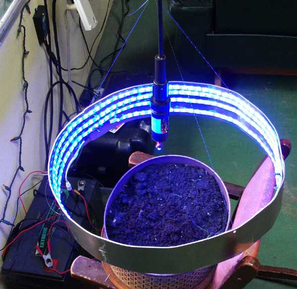
An LED Plant Growth Lighting Idea
Quite a while ago, Jim Harrington had given me a 5 meter
flexible RGB LED light strip he had bought, to try out for aquaponics
plant growth. The light can be changed or programmed to emit hopefully
optimum plant growth colors. But the long thin strip seemed to me to be
too dim in any given area unless it was within a couple of inches above
seedlings planted in a long strip, and I was reluctant to cut it into
short lengths and try to wire them side by side.
This month he said he was planting vegetable seedlings and
I gave it back to him. He came up with a novel, practical way to use it
and concentrate the light. He made a circle of sheet aluminum and
wrapped the light strip around the inside in a helix. The whole unit
went right around a plant pot with his seedlings. The light thus comes
at the plants from every direction, so they won't start leaning over
towards a point light source. Much of each light will reflect off the
far wall aluminum and go down, too. An aluminum or aluminized plastic
top piece of some sort will ensure that most of the light is going to
the pot. The solar panel he is using, planning "off grid" gardening
including for the arctic, will thus need a to provide an absolute
minimum of power to obtain maximum lighting effect.
There is also a relatively bright blue LED light hanging
directly over the pot.
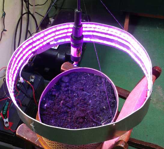 Above, Magenta lighting.
Below, Blue.
Variable Transmission & Sprint Car: Frictionless Centrifugal Clutch
Making
I continued the Sprint variable transmission
work of
January, at an equally leisurely pace. It was almost the only project I
did physical work on, but there just seemed - and seem - to be
many other things to do including other research. With a 'dremmel'
cutter
tool, a 90° adapter and a wood/soft metal cutting bit, I cut the
slots in the
centrifugal clutch drum from a narrow "U" shape as sawed on the bandsaw
many moons ago to a broader "V"
shape
with 45° sides. I filed them smooth and then (more or less)
polished the whole inside of the drum on a polishing wheel.
On the 9th I installed the motor in the car without the
transmission and ran it. The phase wires, carefully marked with colored
tape, had been wrong. Switching them got the motor running nicely in
both directions - with smoother control from the Kelly BLDC controller.
One problem down!
 Then I designed new shoes for the centrifugal clutch. First I cut a
sample
shoe on the bandsaw.
Then I designed new shoes for the centrifugal clutch. First I cut a
sample
shoe on the bandsaw.
Part of the slow progress was being unsure about strike
angles
with a hinge pin point that had to be itself at an undesired angle in
order to be within the drum and on the rotor disk. The strike and
rebound angles actually get complicated when one considers that the
disk is spinning faster than the drum. The 45° strikes are supposed
to be relative to the drum; the angles on the input disk matter less.
At one point I
thought I might use a sliding type of shoe that would go straight in
and out and I made a sample of that, but then I figured it would wear
out fast, and it might jam. I finally decided the first design was
about right after all and better (or at least more practical), and went
about manually writing
G-code to produce
10 of them until it looked about right on the screen. I then routed out
a sample of thin plastic. Several samples later it looked about right.
On the 25th I got 3 of the 5 pairs of plastic shoes
made, using 7/8" thick UHMW. (More ideally they should have been about
1.25" thick - the drum is 3" wide. I had lots of 7/8 and no 1.25".)
Making the last 2 pairs, four shoes in one shot, the router bit snapped
in
the middle of the work. (was it dull?) By not panicking and letting it
finish as if it was still cutting, I preserved the "home" position and
commanded the router
to return to it, so I could rout out the exact same path the next time
on
the same piece of plastic. (I was doing it in two passes anyway in the
thick plastic.) By the next afternoon I had 10 identical shoes.
On March 1st I obtained some 5/8" square steel rod and cut
the first weight to go on the shoes. The 2" length said exactly 100
grams on a scale: my target weight. I look forward, somewhat nervously,
to finishing it, installing it and trying it out.
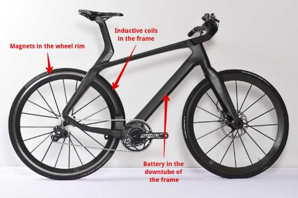
An E-Bike with Motor Components
Around Wheel
In 2012 (see especially TE News #59) I proposed to place 6
"Electric Hubcap" type motor
coils along a bike frame by the wheel rim, and put magnets all around
the rim of the
wheel, to turn a bicycle into an efficient E-bicycle with no more
moving parts than it already had. Amongst all the other projects, I
didn't get around to making it. Now a friend has sent me a link to a
company that has done it, except they designed a whole new bike
around the idea. They seem to have used radial or transverse
flux.
The article points out a potential mechanical problem:
"One current disadvantage of this “Maglev Transrapid technology” is
that the wheel rim magnets and inductive coils must be relatively close
together for it to be an efficient system. That could be a problem if
the wheel rim is not very straight or if debris gets between the rim
and inductive coils in the frame. It will be interesting to see if this
issue can be overcome in the near future."
While my plan wouldn't be immune to this problem (and
magnets may pick up debris), the axial flux motor has a 1/2" flux gap
between the coils (to be mounted to one side of the wheel) and the
rotor supermagnets on the wheel. That is at least a lot of elbow room.
(Here is a place a reluctance motor with its tiny flux gaps might be
problematic to fit reliably.)
Now, let's make that an axial flux BLDC type motor with AlNiCo 5
coil cores. (see Electropermanent Magnets and Motors, below.)
That might well ride along under motor power for hours with only a few
batteries to power it. (eg, 20 NiMH D cells for 24V)
Miles Electric Cargo Truck Repairs
On March 1st I took someone up on his offer to help out
with the Miles electric cargo truck, which has done nothing but sit in
the yard since I found it was intermittent and thus unreliable to
drive. Of all problems, intermittent ones are generally the hardest to
solve, when something unknown quits 'randomly' while in use. He came
over and in accord with his idea of disassembling a few things we
managed to extract the motor shaft encoder "reader" (which I am
virtually certain is the problem) from the front end of the motor,
reaching down from above in the cab instead of crawling under the
truck. We couldn't see it under a metal plate, but we could feel it and
reach the screws from in front. He had the valuable idea to insert his
cell phone, which had a light, and take excellent very close-up
pictures, from which we could see where the screws were and what to do
next, by feel. (Where did my 3rd new inspection mirror go?) The
pictures were also vital in that we e-mailed them to Canadian Electric
Vehicles so they could identify what part was required. They had them!
for 81$. I ordered one.
In fact, the slotted interrupter wheel on the end of the
motor shaft looked immaculate and clean, so it was just the LED and
phototransistor assembly (the "reader" according to CEV) that were
probably quitting randomly. I had ruled out most other possibilities
when I discovered that unplugging the plug at the motor controller and
plugging it back in (hence cycling the power to the reader) seemingly
always brought the truck back to life. And some of the screw sockets
holding the encoder together had a bit of corrosion (visible in the
pictures), which itself made the delicate miniature circuit board
suspect. All it takes is one tiny bad corroded solder joint. Far less
likely, it could be something in the controller itself, or in the
wiring.
I'll only be sure once I install the new part and have
driven at least a few trips with no further problem.
Electropermanent
Magnets
and
Motors
On the 13th Leonardo Janus of "Elionix" (see his new DES
battery electrolyte in an earlier TE News) sent me a video link to a
game-changing new idea for motors: "electro-permanent magnets". [https://www.youtube.com/watch?v=n4YD8Nvyfa4]
As shown, dual magnet combinations (one FeNdB and one
AlNiCo tied together with "keepers") were used which could be turned
either "on" or "off" by pulsing a coil around the AlNiCo magnet in one
direction or the other.
 The Principle: In the original version, the
AlNiCo magnet is
always fully magnetized, but in
The Principle: In the original version, the
AlNiCo magnet is
always fully magnetized, but in
one direction or the other depending on the polarity of the current
pulse that
magnetized it.
In one direction the combo, with the magnetically soft iron magnetic
circuit
connections,
makes a strong external field, in the other it doesn't - the magnetic
circuit is internal.
 In a more practical configuration the straight
top and bottom (soft magnetic)
In a more practical configuration the straight
top and bottom (soft magnetic)
bars deliver high flux to objects near the bars. The bar at
the right is attracted
only if both magnets are magnetized in the same direction. A magnet
above (or
below) would also be repelled then, if the pole faced that magnet's
like pole.
AlNiCo, actually FeAlNiCo
and sometimes with a few minor elements, is the strongest
permanent magnet material discovered before rare earth magnets. It has
been widely used in speaker magnets, guitar pickups, and other places
where strong magnets are needed. Rare
earth magnets take a whopping jolt of current or magnetic field to
change their magnetization, but AlNiCo 5 takes only a fraction as much,
say 5%.
I keep
hearing rumors about motors that give very much longer range to
vehicles, for example the "Zero" Electric Motorcycle, and Troy Reed's
2011 Geo Metro video on youtube. ("You can drive it around all day.")
Details have been
sketchy, but these magnets would surely be how it's done. It sounds too
good to be true, but I don't see any flaws in the theory (so far,
anyway).
Certainly motors can be, and apparently are now being,
made using the above magnet configuration. But I can't help think it
could be
done more simply.
Instead of just having full-strength "on" or "off", modulation of the
strength of the
pulses should allow low to high magnetization (in either direction) of
a single AlNiCo5 magnet core for
low to high power motor
operation, with weaker pulses more or less demagnetizing the magnets
when
they're not wanted. And it should run more smoothly at lower power.
Ideally it would work like this:
- In BLDC motors, the stator
electromagnets attract and repel permanent magnets on the rotor to
cause it to rotate. FeNdB 'supermagnets' are usually used on the rotor.
It is very hard to change the powerful magnetization of this alloy -
they are
very "permanent" magnets. Someone once told me that a million amp pulse
for a microsecond is used to generate enough magnetic field magnetize
them. An interesting feature is that although it's a truly impressive
current, it's only one coulomb, one amp-second, of total charge.
- Usually very "soft magnetic"
material (plain iron or alloy) is used for electromagnet coil cores.
This won't hold a magnetic charge - can't be magnetized to be a
permanent magnet - in order that as it is electrically magnetized from
'north' to
'south' and back as the motor rotates, no extra energy is wasted to
demagnetize it when reversing polarity. The coils are using power for
their entire "on" time over the appropriate part of the rotation in
order to continue to attract or repel the rotor magnets for that time.
This is typical motor theory and operation. Conventional logic until
now has said
this is how it has to be.
- Permanent magnets made of alloys
of aluminum, nickel and cobalt, "AlNiCo", and particularly "AlNiCo 5",
can have fields as strong as "supermagnets". However, they
require a much smaller current pulse to magnetize and demagnetize, much
less than a coulomb. They are
harder to induce a field into than "soft" magnetic material, but once
pulsed they will hold the magnetic charge. (FeNdB: ~1,000,000 A/m;
AlNiCo5: ~50,000 A/m; Soft Fe: 160 A/m)
- Thus, if an AlNiCo 5 magnet was to
replace the soft magnetic coil core material, one would have a
"permanent" magnet that would be magnetized by a single short pulse of
current to the coil.
- Once it was magnetized, a rotor
magnet would continue to be attracted to or repelled from that stator
magnet without using any more electricity, until the magnetization
strength and polarity was deliberately changed by another short pulse,
of reverse current.
- So again: where a "regular" motor
coil has to stay energized and draw current over an entire segment of
motor rotation, the AlNiCo 5 core coil only needs to be pulsed "on" at
the rotation start point and pulsed "off" again at the end point, with
a
weaker reverse pulse. Through the whole desired arc, it's a "permanent"
magnet driving the rotor magnet. The amazing electricity saving
potential becomes
apparent.
- Current in a coil increases over
time with
pulse length. Thus the maximum current can be set for magnetizing or
demagnetizing simply by timing the length of the pulse - no current
sense shunt resistor is required. To obtain the required very high
current in the minimum possible pulse width, very few turns of very
heavy wire would be used. (Perhaps my usual 21 turns of #11 wire, but
with the phase coils wired in parallel instead of in series? Or maybe 2
sets of 10 turns, in parallel?) The magnet magnetizes
to the maximum current that hits
it, even if it's only on for a microsecond. A microcontroller based
motor controller could "learn" (or be programmed with) the pulse
lengths required to obtain
smooth control of the motor from low to full power. (Since single
phases
would need to be individually controlled, a full bridge is probably
required for each
phase, doubling the number of driver transistors. Must think about
this!) But the transistors will be on for such short lengths of time
they can probably be downsized without risk of overheating.
Possible cautions?: One
thing that might militate against this simpler electropermanent magnet
model is that AlNiCo magnets, being said to be easily demagnetized by
an external magnetic field, might become demagnetized by the rotor
magnets during a single pass as they go by, strongly enough to greatly
decrease their intended attraction or repulsion of those magnets.
However, there is a large flux gap in axial flux motors, and the stator
magnets are supposed to be off anyway at the nearest points, as rotor
and stator magnets pass by each other. So I expect it would take many
passes to gradually demagnetize an AlNiCo5 stator magnet -- which is
being repeatedly magnetized and demagnetized in both directions by
electrical
pulses anyway.
The other possible caution is that the short magnetization
and
demagnetization pulses might just possibly take as much or more energy
than
powering a regular coil ON for the entire duration. Given that the
pulse if heavy wire is used will be so short, that
this also seems improbable. And of course lower
RPM motors such as the Electric Hubcap axial flux types will also have
fewer pulses per second than very high RPM ones, and the pulses require
the same current
regardless of motor speed to obtain the same magnetization.
Given these factors plus given that electropermanent
magnet motors made so far are claimed to be so good, I'm going to
dismiss both concerns as being highly unlikely. And the factors are
adjustable.
A reluctance motor could also be run by the same system.
Since the rotor iron doesn't care about magnetic direction and is
attracted to either north or south magnet poles, the cores must be
demagnetized pretty fully when they aren't wanted as well as magnetized
when they are. Again, carefully tuned weaker reverse pulses could be
used to
demagnetize the AlNiCo, rather than going to the more physically
complex two-magnet system shown in the video.
For either, the single magnet also
delivers maximum flux, to the steel rotor or rotor magnets. And reverse
pulses are required to demagnetize so the unipolar motor controller is
"out". A whole new type of controller with different operation is
required.
The most mind boggling thing is that this electro-permanent magnet
motor idea is so simple, yet no one
seems to have thought of it before. (If Bedini's motors use it, it was
never explained so I understood it.) Rather than in motors, its chief
use so far seems to be in heavy lifting of magnetic materials such as
steel plates, where the magnet can be pulsed on to lift them and then
pulsed off to let go of them. It seems likely that's what it first was
invented
for. Certainly nothing like it ever crossed my
own mind. But I was unaware of the magnetic properties of AlNiCo.
This would add a whole new dimension to the idea of
"ultra-efficient" drives. It could probably give typical electric cars
sufficient range for all day highway driving (recharge at night on long
trips), and the power taken from the power grid (or other source) for
typical/regular driving will be quite minimal. On March 1st I found
AlNiCo 5 magnets of similar size and shape to my usual coil cores
so I can make a motor easily when the time comes. With a small shim (as
they're not identical inside diameter) I can use the same
motors and simply replace the coils, and I can use all the same motor
making
molds to make more BLDC motors.
The BLDC motors being pretty much identical, the
controllers will be the part needing effort to develop. The reluctance
motors will need some redesign. Something much like the type I made one
of is probably more practical in this case than my proposed "transverse
flux" type, unless AlNiCo can be had in the form of metal plates that
can be cut by CNC abrasive waterjet.
In Passing
(Miscellaneous topics, editorial comments & opinionated rants)
Rising Financial Woes
The long predicted financial events, strongly foreshadowed
since the 2016 new year, seem to be starting to unfold. Major banks
withdrew much of their remaining gold from the COMEX
inventory, leaving 500 "owners" for each piece of gold remaining.
Demand for the actual physical metals keeps breaking records around the
world as people start to lose trust in paper assets. Gold
and silver rose about 10% over a week, and on the night of February
10th started to explode, rising a further 5%. The stock markets looked
dismal. Then the manipulators moved in and patched things up again -
don't look at that man behind the curtain, everything is rosy!
But one hears that shipping, rail and trucking indices
were at multi-decade lows, more major chains were closing more stores
with layoffs probably totaling 100s of thousands in the USA, and
manufacturing continued to drop - all continuing trends over several
years. Teamsters union pensions in the midwest (or was it just
Michigan?) were all cut, by as much as 50%, the funds having been
"borrowed" (AKA looted) by government and with almost no possibility of
reasonably safe interest bearing investments on the rest in the present
environment. (You worked your 35 or 40 years and were told from the
start your pension terms. Sorry, we spent your money!) Farmers strikes
and riots in Athens speak of the dreadful pension cuts and tax demands
being made on people there, and it's probably happening in various
cities around the globe, so common that it's mostly unreported even in
the alternative media. Many banks will need bailouts, one or two
Italian one being said to be on the brink. Deusche Bank, Germany's
largest (and with 70 trillion dollars of derivatives exposure), was
said to be struggling day to day for funds to keep its doors open. With
the low oil prices, virtually all the shale oil frackers will soon be
declaring bankruptcy. With over 19 trillion dollars of debt (and far
more off the books) the USA has over 3 trillion dollars in assets...
but 1/3 of those "assets" are student loan debts, which are mostly in
default -- non-performing loans are everywhere! Yet the US government,
having lit the middle east, Ukraine and north Africa on fire, continues
to spend over 1/2 their budget on the military, to threaten and posture
aggressively.
Aging populations with (thank goodness!) fewer young
people illustrate Harry Dent's The Demographic Cliff - aging
people don't buy larger homes, fancy new cars and the latest gadgets,
and so the economy is bound to slow. But now migrants from areas still
having high population growth threaten the tranquility of the
established West, especially in Europe. And it is said the USA will be
over 1/2 Hispanic by 2030.
"Alta Web Bott" Reports make quite detailed incredible
predictions of things to come, and not without some successful
predictions although the timing for the events is often off. The guy,
Cliff High, says he sends out "spiders" all over the web to search for
out of place words (like "battleship" on a gardening site?) and then
sorts them and finally reads the sorted data. Where he really comes up
with this stuff I don't know, but much of it sounds all too plausible.
(See HalfPastHuman.org or listen to summaries by 'jsnip4' on youtube
for more details.)
The January and
February reports predicted for
2016 and 2017: a mid-level bank failure that would spread to engulf the
global financial system, shortages, rationing of many things,
riots, break-ins to sensitive government documents and arrests by US
marshals of highly
prominent figures whose activities have at last been fully exposed.
Much infighting in all that.
The bank failures are supposed to leave people celebrating
briefly that at least they don't have to pay
back their credit cards and other bank debts. Incredibly hot weather is
supposed to strike the west coast this summer, killing people and
filling hospitals and "cooling centers", and paralyzing ground and air
traffic. Incredible property tax
hikes will lead to abandonment of condos and tax revolts. All for
2016 and 2017.
Another person on youtube, Mike Boutwell, reading from the
same report, remarks "This will hit a lot of people like a brick in the
face."
What really happens we'll have to wait and see, but don't
expect it'll be "business as usual" for many more months. More and more
it looks like any of a number of dominos could fall at any time and set
off a chain reaction where everything will suddenly slip out of
control. I'll continue to sing my old song: get your storable foods
stashed away, fuel to 'get out of dodge' or whatever if required
(better still a nice electric vehicle!), and some silver to trade with.
Even if you're not convinced, how much do you spend per year on house
insurance, just in case? You'll probably never use that insurance. How
about investing in these other potential lifesavers - just in case?
Besides, with rising prices, food bought now is cheaper than food
bought in a few months from now - it's actually a money saver.
USA Election Rigging
Hold the presses! We heard earlier about Hillary Clinton
"winning" a state (Iowa?) because of democrat "establishment super
delegates", in spite of Bernie Sanders clearly beating her in votes and
bona-fide elected delegates. Today, March 3rd, it came out that in
several states, votes for Donald Trump were coming out of the machines
as votes for other republican primary candidates. There were thousands
of calls from incensed voters to an 'electoral fairness' agency whose
name escapes me. We can surmise that Clinton will be the democrat
faction candidate, and that Trump will not be the republican faction's
rep, regardless of the wishes of the people.
Can we expect any better when the actual election is
underway? Even if everyone picks any other candidate, it seems that the
votes will switch themselves to the oligopoly's choices. It is also
probable that a number of other candidates will split the vote even
without rigging, so even if a majority of Americans choose "anything
but republicrat", that's what they'll get anyway. It is becoming
abundantly clear is that there is and will be no even nominally fair
election in the USA in 2016. Until and unless the sort of events
foreshadowed above unfold, we already in fact have an
oligopoly-dictatorship.
For more on "vote splitting" on single "illiterate's X"
ballots, see TE
News
#74 and for various possible solutions, my new site Hands-On Democracy.
Humorous or not...
A word is worth one millipicture.
or
A word is worth 2 pixels.
More and more rat traps were all set up with aromatic bait. Then it was
announced that all the rats were gone. After much debate about all the
dangerous set traps, it was decided to set up a debaiting society.
Newsletters Index/Highlights: http://www.TurquoiseEnergy.com/news/index.html
Construction Manuals and information:
- Electric Hubcap Family Motors - Turquoise Motor Controllers
- Preliminary Ni-Mn, Ni-Ni Battery Making book
Products Catalog
(Will accept BITCOIN digital currency)
...all at: http://www.TurquoiseEnergy.com/
(orders: e-mail craig@saers.com)
Daily
Log
(time accounting, mainly for CRA - SR & ED assessment purposes)
Feb 1: Installed motor in Sprint and
tested operation.
Feb 1-2: Working on this newsletter.
3:
4: Disassembled much and removed clutch rotor & drum from Sprint to
work on them. Ordered "nickel foam" for battery electrodes.
5: Edited "Hands-On Democracy" text - uploaded to web page.
6: Found 'right angle cutter' attachment and cutter for 'dremmel' tool,
bought a new file, and ground and filed centrifugal clutch drum slots
from narrow "U" to broader "V" shape with 45° sides. (90° angle
at bottom.)
7:
8: (yet another migraine.) Inspected "V" points on centrifugal clutch
shoes. I thought they were badly worn, they were okay for another test.
9: Tested motor and changed connections.
10: Worked on new centrifugal clutch design ideas. (Added "Choice
Ranking Vote" (CRV) section to Hands-On Democracy)
11: Still on clutch design - another improvement (rotor slots) or two.
12: Cut sample UHMW clutch shoe to check fit.
13: Didn't like it. Decided hinge pins was better system.
14: Cut out sample shoe for that system.
15: (Worked on personal income tax)
16: Hands-On Democracy additions.
17:
18: Hands-On Democracy additions.
18 & 19: Figuring out centrifugal clutch strike angles
20: Put together G-code to produce the plastic shoes (initial version)
21: Tried again. Versions 2,3,4 and 5. Hands-On Democracy additions.
25: Cut 3 pairs of final version shoes. (Router bit broke.)
26: Cut remaining 2 pairs.
27: (Finished, sent personal income tax)
28: Hands-On Democracy additions. Tried again to buy Dremmel right
angle attachment.
29: Bought a 'new' aquarium for the tilapia breeding tank for
aquaponics.
March 1: Took shaft encoder "reader" off Miles electric truck for
repair. Ordered a new one. Bought steel and cut the first of 10 weights
for the clutch 10 shoes. Found a web site offering the right size and
shape of AlNiCo5 magnets.
2: Worked on this newsletter. Cut 5 more weights. Conversed with magnet
company by e-mail.
3: Newsletter.
Electric
Hubcap
Motor
Systems
-
Electric
Transport
Electro-Permanent Magnets &
Motors
Well, I wrote this here when I first heard of
electropermanent magnets.
Then I decided to do a "feature article" on the subject. There seem to
be enough different material in here to be worth reading if one is
"into" the subject, so I'll leave it in.
Checking my e-mail
on the 13th, I found a link to a video
about magnets that could be turned on or off, and would remain in
either state once power was removed. [https://www.youtube.com/watch?v=n4YD8Nvyfa4]
This
device
looks
like
a
real game-changer!
Essentially they were two magnets: a supermagnet that
couldn't be modified, coupled with steel "keepers" at both ends to an
AlNiCo "regular" permanent magnet that be switched in polarity with a
DC electromagnetic coil, energized one way or the other. The pulse to
magnetize the AlNiCo magnet could be as short as a microsecond. Thus
very little energy is used to switch it. If both magnets were
magnetized in the same direction, the "regular" AlNiCo magnet
reinforced the FeNiB magnet beside it and they would attract metal
objects. If it were magnetized in the other direction, the two opposite
magnet poles would be "shorted" through iron pieces connecting the
ends, and it wouldn't pick up anything. The AlNiCo was described in the
article as "soft magnetic material". But surely if it was really
"soft", it wouldn't hold a magnetic charge at all. So either it's
simply soft"er" than the FeNdB, or I don't have the theory straight.
I had heard about motorbikes, and Troy Reed's car, getting
fantastic driving range, but details on the motors were to say the
least sketchy. This video seems to clear up the mystery.
Every time I think I've got "the ultimate" in electric
propulsion motors, somebody sends me some link to something better! Now
here is another worthy motor project, a game changer as I say, to make
obsolete the way I'm doing it now.
I can now think of a couple of possible ways this idea can
be used in motors. Perhaps easiest, why not have a single "permanent"
magnet that can be energized either direction, used in a BLDC motor
with a regular supermagnet rotor? Each coil need only be turned on for
a microsecond, to attract or repel the nearest rotor magnet, for
milliseconds or tens of milliseconds (thousands of times as long as the
pulses), depending on the RPM and
configuration.
The first version could be a modified Electric Caik motor,
which could be tested in the outboard. In the motor, the modification
would consist simply of replacing the iron powder donut coil cores with
a more "hard" magnetic material that would hold its magnetic charge.
(Usually that's just what you want to avoid!)
The motor controller would have to be set up to put out
just the short pulses, just one pulse per step. Then, some pulses would
have to be be missed if full power wasn't needed. Unless there were to
be still shorter, or weaker, pulses to demagnetize without magnetizing
in the other direction, allowing the rotor magnet to "drift" by an idle
coil wouldn't be an option.
But why couldn't shorter and hence weaker pulses be
tailored to partly magnetize, or to demagnetize, the magnets? The motor
doesn't need full power all the time, and that would be a good way to
modulate them.
No doubt a microcontroller - controlling three full bridges to
drive the mosfets - would be the way to handle the unique aspects of
the operation. No available motor controller chip is designed for this!
On looking things up, it seemed that "AlNiCo 5" looked
like a good alloy. It has similar strong pull to FeNdB supermagnets,
but is easily magnetized and demagnetized. That seemed to say they
should work well in BLDC magnet-rotor motors per above. So I looked for
some the same size as my Electric Hubcap type coil cores. I did find
some that looked like they might be somewhat suitable, or 6" long 2"
diameter rods that might be cut to length, 5 magnet cores per rod.
On the other hand, I haven't looked into this very far yet
and I'm not certain I understand all the details. I shall be checking
into it in more detail before trying anything.
And then there's Bedini... His motors are supposed to use
single pulses to run. And then they collect electricity off the coils
as in a generator! Now I can see how this might produce extra energy -
if the pulse magnetizes a magnet, input energy is only required to
magnetize it and demagnetize it again at the right times. Maybe it's an
"undocumented feature" of his motors that's really how they work? Maybe
that he didn't realize himself but he picked steel for his coils that
holds magnetism, or holds it until it's used as a generator later in
the rotation? But that's all just speculation.
Electric
Hubcap motor, Chevy
Sprint & Variable Transmission
The Theory of The Frictionless Centrifugal Clutch
Insufficient traction of the centrifugal clutch seemed to
be the big problem with the drive. How is it supposed to work?
This clutch, designed for effective operation at lower and
marginal RPM.s, has a slightly different
operating principle than other centrifugal clutches: instead of the
shoes flying out with centrifugal force and engaging the outer drum by
friction, these shoes are made of slippery UHMW plastic, and have
45° "V" shaped lower points. (UHMW - ultra-high molecular weight
polyethylene - long polymer molecular chains. The two 45° angles,
for forward and for reverse, form a single 90° "V" angle.) When
they fly out, these
points slide easily along the polished aluminum drum until they reach
slots in the drum wall. When they hit the far wall of
the slot, they are forced to bounce inward for the input rotor to
continue rotating. The momentum of the weighted shoes bouncing off the
slot wall
is what produces thrust to the output drum. With the low friction
of the plastic on the aluminum, this should allow partly engaged
operation at "marginal" lower RPM.s with low losses and little heat,
with the input drum turning
faster than the output.
The angle of bounce that produces the most force in the
output drum is 90° - a straight-on hit with reflection straight
back. A hammer works that way. That angle of course stops the hammer.
We don't want to stop the motor. The best angle of impact and
reflection to impart the most force with lowest loss of motor speed is
45°, with the shoe bouncing 'directly' inward (90°) while the
input rotor/motor continues to turn.
Once the drum is turning at sufficient speed and the input
torque isn't too high, the points (or at least one point) will
centrifugally "lock" into the grooves and the clutch would be locked,
the output turning with the input.
In keeping with the large mass to be moved - the car - the
drum is 3" wide instead of a typical 3/4" for small rotary clutches. In
keeping with the low RPM.s, it's 9" diameter instead of a typical 4".
The car wheels will only be doing perhaps 1200 RPM on the highway and
600 in town. The drum speed depends on the final drive ratio. If it's 3
to 1, that's still only around 1800 RPM of the drum in town at 50 Km/Hr.
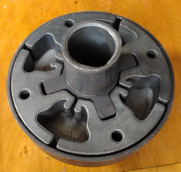
Slots and Points/Dogs
 I had
impression that the 45° "V" shaped "dogs" on the
plastic shoes had
been partly worn off of it by the edges of the aluminum slots in the
drum. The slots were cut with a bandsaw. I had scraped them with a tool
that smoothed off and beveled the corners, but essentially the flat
plastic faces were still hitting against a 90° corner - a "V" point
hitting a "U" hollow - and that was wrecking them. What was needed
surely was two flat faces hitting each other. That would mean filing or
cutting out all 24 slots in the drum so they were 45° "V" shaped
slots instead of "U" shaped.
I had
impression that the 45° "V" shaped "dogs" on the
plastic shoes had
been partly worn off of it by the edges of the aluminum slots in the
drum. The slots were cut with a bandsaw. I had scraped them with a tool
that smoothed off and beveled the corners, but essentially the flat
plastic faces were still hitting against a 90° corner - a "V" point
hitting a "U" hollow - and that was wrecking them. What was needed
surely was two flat faces hitting each other. That would mean filing or
cutting out all 24 slots in the drum so they were 45° "V" shaped
slots instead of "U" shaped.
I discussed this with Jim Harrington at breakfast on the
6th. I thought maybe a 'dremmel' motor tool with some cutter might
work, but perhaps there was some sort of 'right angle' dremmel tool -
shaped like an angle grinder - that would fit inside the drum. Perhaps
a visit to a tool store? We stopped by his shop. He had a right angle
attachment for his demmel tool. I borrowed that, and found a suitable
rotary cutter in my own attachments.
 I spent the afternoon changing the vertical
slots to
45° "V"s. I was guessing the angles at first, then I reasoned that
while one may be in considerable doubt about most 'eyeballed' angles,
vertical and horizontal can be judged pretty accurately by eye. If I
clamped the rotor so the slot was at 45°, those would be the
angles. Logic said that if there were 24 slots, a slot 3 up from the
bottom one would be 45°. It looked to me more like the fourth slot
was 45°. I got out a plastic 45° drawing triangle and it was
indeed the third slot, not the fourth. That shows how far off my
freehand angle estimates might have been, but now the walls of the
slots I was cutting were to be either vertical or horizontal.
I spent the afternoon changing the vertical
slots to
45° "V"s. I was guessing the angles at first, then I reasoned that
while one may be in considerable doubt about most 'eyeballed' angles,
vertical and horizontal can be judged pretty accurately by eye. If I
clamped the rotor so the slot was at 45°, those would be the
angles. Logic said that if there were 24 slots, a slot 3 up from the
bottom one would be 45°. It looked to me more like the fourth slot
was 45°. I got out a plastic 45° drawing triangle and it was
indeed the third slot, not the fourth. That shows how far off my
freehand angle estimates might have been, but now the walls of the
slots I was cutting were to be either vertical or horizontal.
Although the cutter wasn't symetrical it was cutting into
both sides of the slot. But I thought I should flip it up so both sides
were cut with both faces of the cutter to be the most symetrical. After
grinding the cutter through a few times horizontal, I tried to turn it
vertical, but it bounced and stuttered. So instead, I turned the drum
around so the current slot was 3 up on the right instead of the left,
and turned the cutter to vertical. This worked. (Hmm, I could have just
flipped and rotated the drum so I could have done all the cuts
horizontal.)
After cutting a few I started filing them smooth. The
whole process went smoothly, but it was time consuming to do all 24
slots. The most brilliant thing I did that afternoon was to stop after
doing a few and go out and buy a new file. Not surprisingly, it filed
faster than any of my old ones.
I had, for my original
experimental purposes, taken the
path of least resistance in making the clutch. It was really only 'one
way' and would jam going the other way. The dual 45° "V" is of
course a right angle, 90°, which I got by using a corner of the
rectangles. To get true symmetry, the pivot hinge of the shoes would
have to be straight in line with the "V", which would put it outside
the drum. That would be theoretically possible with a drum open on one
side, a larger input disk outside that open side, and shoes with a
"stem" attached to pins outside the drum radius through the open side.
But that would be inherently weak. Otherwise, the 45° bounce from
an interior hinge point has to use different angles for one direction
than for the other. My "V" points and slots should be quite
slanted, "in italics" to say the least, to have symmetrical forces
forward and backward.
In fact, that's probably a reason for the low force. The
active side should be steeper. Now I think of that, after doing
the "V" slot cutting and filing, symmetrically! It was only as I was
half way through that it gradually started to dawn on me that the other
sides would have to be shallower so as not to jam, and still later that
the one-way active side should be steeper to match the pivot points. If
it doesn't work well I could make pivot pin points closer to the outer
edge of the input disk - where I had them originally - and shape the
shoes' "V" points on the bandsaw - as I also did them originally. I had
changed it for the last version only because they were hard to cut.
(Later it seemed more complicated... read on.)
I thought I would turn the present clutch shoes around so
they would use the un-worn corners of the rectangles. Then the car
would go only forward instead of only backward. To prove a point of
working or not, it makes little difference. Once the point was proven,
the angles would have to be adjusted... or would the active edge angles
have to be optimized in order to get it to work and prove the point?
But when I went to do it (8th), I found that only the
outer bits of the shoes were badly worn - the parts that are seen from
outside. Here they were hitting the support clips that hold the drum
onto its backing disk. I had realized this was inevitable, but I didn't
see any better way to attach it when I was making it. The corner-edge
hitting along the slots was only slightly dulled. That means that
changing the slots to "V"s would make little difference... except that
they were now substantially wider at their tops and in total effect.
Changing to the italic "V" shape might make more difference.
Anyway I decided that it was worth trying again with the wider slots to
see what improvement there might be.
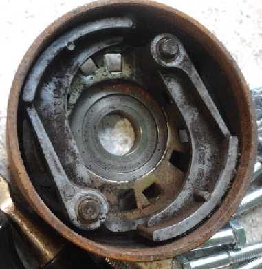
Next something jogged my memory: some centrifugal clutches
didn't have pivot hinges. Instead, the shoe piece slides straight out
to contact the drum. Two I bought quite a while ago from Princess Auto
were examples of that. If I could arrange mine somehow like that, the
straight "V"s would be right, and the forces maximum. Also the slippery
plastic would allow them to slide in and out with little friction. Fat
aluminum blocks on the input rotor disk, holding slippery UHMW shoes
(with weights) that bounce in and out - Ya, ya, I thought, that's the
ticket!
 Commercial centrifugal clutches with sliding
shoes for snowmobiles, motorbikes, etc.
Commercial centrifugal clutches with sliding
shoes for snowmobiles, motorbikes, etc.
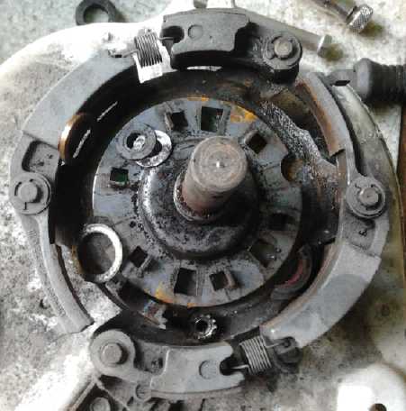 Clutches from a washing machine transmission
with pivoting shoes.
Clutches from a washing machine transmission
with pivoting shoes.
The one on the left would doubtless grab - jam - in one direction, slip
in the other.
The one on the right will press against an outer drum and an inner drum
with strategically placed weight and springs.
On the 10th I considered that I should make this - redo
the input rotor and shoe arrangement. But to get sufficient weight in
the shoes for good forces at low RPM.s, they should probably be heavy
steel, with a plastic "V" face screwed onto the outer end to contact
the drum. Then instead of aluminum, the side walls should be UHMW. Best
might be a single piece of UHMW with four cutouts for four sliding
shoes, almost as large as the inside diameter of the drum to make
maximum length slots to hold the shoes. (The clearance on the small
commercial clutch is about 2mm.) Let's see... The present weight of
each of the 6 shoes is 90 grams. If the new shoes were 1.25" wide by
.75" long by 2.5" high (depending which way you look at it) solid
steel, they'd be 280 grams. (about 120g/inch^3) So 3 times the weight
per shoe, bouncing in a more effective direction (and so imparting,
say, triple the force?), then 8 shoes instead of 6, would likely make
around 12 times the turning force at the same RPM. That seemed likely
to produce results.
A shoe to slide in and out, a lead weight for a
shoe (too heavy!), and a steel rectangle
to slide along a slot in the disk, with a shoe bolted to each side.
 In the evening I came up with a somewhat different plan
than the commercial units: Leave the disk rotor centered in the drum,
so that it will still have 1/2 the shoes on each side, about 1-1/4" on
each side. Instead of a metal "X" for the shoes to slide against, mill
short slots in the rotor, 2 for each pair of shoes. Bolts will clamp
the left and right half shoes together through the slots.
In the evening I came up with a somewhat different plan
than the commercial units: Leave the disk rotor centered in the drum,
so that it will still have 1/2 the shoes on each side, about 1-1/4" on
each side. Instead of a metal "X" for the shoes to slide against, mill
short slots in the rotor, 2 for each pair of shoes. Bolts will clamp
the left and right half shoes together through the slots.
I worked out more details on the 11th. The slots will
contact only the slippery UHMW plastic of the shoes, hold the shoes at
right angles to the drum as the "X" pieces, and allow them to move in
and out by about 5mm - from 2mm clearance like the commercial units to
where the "V" points would bottom out in the "V" slots in the drum.
Bolted to the UHMW shoes and fitting into the profile would be lead
bars for weight. The same bolts that clamp the shoe halves together
will clamp the bars onto the outside.
All great, but by the 13th I started to think of the high
transient forces knocking the shoes to the side. I started to realize
that the commercial shoes wouldn't tend to twist because their feet
were so wide, taking up almost 1/4 of the drum each. And they were
intended to rapidly "latch" by friction against the drum, not to
operate for long
in a slipping mode. My shoes had to
bounce in and out of the "V" grooves - they hit at specific points
along the
rim. The operation just wasn't the same. Could the plastic at the slot
edges take repeatedly rubbing up and down against strong sideways force
on the outer end? Maybe the sliding part should be inserted steel bars?
Then it would need lubrication. If the sliding slot parts got too worn,
or if the lube ran dry, might it tend to jam?
I started to think hinge pins were the better form after
all, and went back to that idea. Since the pivot point had to be inside
the drum on the rotor disk, the best way to keep the forces relatively
even between forward and reverse would be the distance between hinge
pin and "V" slot in the drum where the force would be tangental to the
disk. (Ie, parallel to the edge at the hinge pin. I *think* I have the
right word.) That appeared to be about 2.0". The lead weight would also
center over the "V" point at the 2" mark, and the shoe lengthened
beyond 2" to attach the weight.
Also on the 13th I got some lead fishing weights and a 3Kg
chunk of galena from Jim Harrington to use for the weights. The galena,
natural lead mineral or ore, looked to be reasonably pure lead. I
figured I could melt some of these down in the mini-kiln and cast them
into bars easily enough, rather than trying to source lead bar of just
the size I needed. People warned me to beware of lead fumes. This is
why I would use the kiln. With a torch, the temperature on the outside
can start the lead boiling and giving off fumes before it's melting on
the inside. In the kiln, I won't let it get hot enough to give off
fumes. If I use the galena, I will still be cautious because of the
unknown impurities in it.
 On the 14th I
cut a sample shoe out for size and tried it
for fit. A 1"x~1"x2" lead weight would go in the hollow space, perhaps
100 grams. I carefully cut out the shape on my scary big bandsaw, and
drilled the hole for the pin, without incident up to the point where
the drill was stopped, all operations completed. The thick UHMW plastic
(as usual) had wound itself up the drill bit as it drilled. As I
twisted the chuck backward to wind it off while holding the piece with
my left hand, my middle fingernail caught and cut a gash in the knuckle
on my left index finger. Ugh, where's the bandages? Accidents are so
often when no danger is suspected! The piece seemed
just about right, except for tending to jam if the middle piece was
turned clockwise. Making the one edge just a little shallower angle for
'reverse' should take care of that. And of course a steeper angle would
be better for 'forward' - the italic "V" slots and points. Well,
I could still do them, digging all the slots a little deeper
and wider. I decided it should be done.
On the 14th I
cut a sample shoe out for size and tried it
for fit. A 1"x~1"x2" lead weight would go in the hollow space, perhaps
100 grams. I carefully cut out the shape on my scary big bandsaw, and
drilled the hole for the pin, without incident up to the point where
the drill was stopped, all operations completed. The thick UHMW plastic
(as usual) had wound itself up the drill bit as it drilled. As I
twisted the chuck backward to wind it off while holding the piece with
my left hand, my middle fingernail caught and cut a gash in the knuckle
on my left index finger. Ugh, where's the bandages? Accidents are so
often when no danger is suspected! The piece seemed
just about right, except for tending to jam if the middle piece was
turned clockwise. Making the one edge just a little shallower angle for
'reverse' should take care of that. And of course a steeper angle would
be better for 'forward' - the italic "V" slots and points. Well,
I could still do them, digging all the slots a little deeper
and wider. I decided it should be done.
There were already 5 holes
equally spaced around the rim
of the rotor from some previous attempt. There were 24 slots in the
drum. 5 pairs of shoes would mean that one pair of points would hit one
slot at a time in quick succession, rather than all the points striking
at once. Would that have the desired effect? I decided to try it. If it
worked, it would be the smoothest. If it worked. I still didn't have
any proper software to draft the shapes. The curves would be
complicated to work out directly in G-code. I decided to approximate
them as a series of short lines. Each shoe would be cut out with a
series of relative moves, and between those, 10 absolute moves to
position the router for the start of each shoe to make all 10. The
italic "V" dog/point angles could be seen and adjusted to
45° relative to the hinge pin angle for optimum bounce.
Ideally I'd use 1.25" thick UHMW, but I had 13/16", 1" or
1.5". Or
there was thinner stock which could perhaps be doubled. Simplest would
be to use 1" and accept that the points would only be using 2" width
within the 3" drum slots. If it worked well - and if there were no
other desired changes anyway - I could worry about optimizing the
widths better when the first set wore out - if they did wear out over
too short a span of time. (I used the 13/16" for
the first experiment, since it was the one thickness I had plenty of.)
On the 18th, I still wasn't sure about angles. I didn't
want to grind new angles in the drum and then have to undo them again!
And they would get wider and deeper with each cut. I had to have a
clear concept. How did the forward and reverse angles of the hinge pin
figure in? Wasn't it the weights, to be positioned directly over the
points, that would push the shoes out centrifugally? If the rotor was
spinning a constant speed, wouldn't they go out tangent to the start of
the slot until they hit the far side, rather than at the hinge pin
angle? Weren't the angles of the points hitting the drum then
independent of the hinge pin angles? Then again, the angle of
relection/bounce would be different for the input disk than for the
output drum because they would be rotating at different speeds. The
whole thing was more complicated than I'd realized. It seemed likely
that the hinge pin point would make the action somewhat different in
one direction than in the other, but it probably wasn't as much
difference as the hinge pin angle by itself would indicate. If one
direction worked better than the other, one would of course pick the
better one as forward and the other as reverse. And the test shoes
would be symmetrical and could be reversed. Or, the shoes on one
side could be reversed and it would be symmetrical. But the uneven
forces would stress the pins. The angles of points and
slots on production prototypes and production units could be adjusted
optimally for both directions.
 Perhaps the only critical point was that the "V" dog must
not actually jam if one fell into one of the "V" slots while the
mechanism was stopped. I checked this out with my sample shoe on the
19th and pinned at the pivot point and with disk holes correctly
positioned, it didn't seem it could jam anywhere. I started in on the
G-code to rout out 10 identical shoes but was soon interrupted. I got
an initial version designed on the 20th, but didn't find time to get
everything set up and make a sample. On the 21st I made 5 versions of
sample shoes before getting the dimensions close enough to use, and a
couple more later. On the 25th I figured I had them nicely figured and
made a pair. It seemed to fit well and I made two more pairs. I now
needed more bolts, nuts and washers and went off to do some shopping. I
told the router to do all the remaining 4 at once. Part way through the
first pass, the router bit snapped off. (I suspect it was getting dull
- it didn't seem as smooth as usual.) Since the router now wasn't doing
anything, I let it finish its course not cutting instead of shutting
the machine off. That way when I told the router to move to "home", the
starting point, it "knew" where "home" was to find it. From "home" it
could cut exactly the same path again next time and redo the job. It
was too late to go out and buy a new router bit, so that was it for the
day. I finished the next.
Perhaps the only critical point was that the "V" dog must
not actually jam if one fell into one of the "V" slots while the
mechanism was stopped. I checked this out with my sample shoe on the
19th and pinned at the pivot point and with disk holes correctly
positioned, it didn't seem it could jam anywhere. I started in on the
G-code to rout out 10 identical shoes but was soon interrupted. I got
an initial version designed on the 20th, but didn't find time to get
everything set up and make a sample. On the 21st I made 5 versions of
sample shoes before getting the dimensions close enough to use, and a
couple more later. On the 25th I figured I had them nicely figured and
made a pair. It seemed to fit well and I made two more pairs. I now
needed more bolts, nuts and washers and went off to do some shopping. I
told the router to do all the remaining 4 at once. Part way through the
first pass, the router bit snapped off. (I suspect it was getting dull
- it didn't seem as smooth as usual.) Since the router now wasn't doing
anything, I let it finish its course not cutting instead of shutting
the machine off. That way when I told the router to move to "home", the
starting point, it "knew" where "home" was to find it. From "home" it
could cut exactly the same path again next time and redo the job. It
was too late to go out and buy a new router bit, so that was it for the
day. I finished the next.
It seemed lead isn't as dense as I thought, 11 g/cc where
I had been thinking upper teens. Then, it didn't look like it would
need a very big piece to gt 100 grams. Why not use steel instead? On
March 1st I got some 5/8" x 5/8" steel rod. I cut one 2" length to fit
in a shoe (does that make it a foot?) and it weighed exactly 100 grams.
On the second I cut and shaped 5 more.
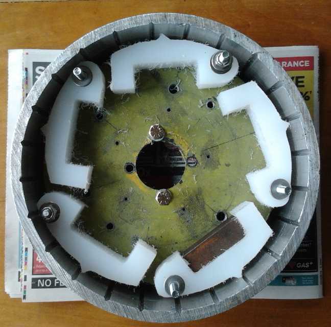
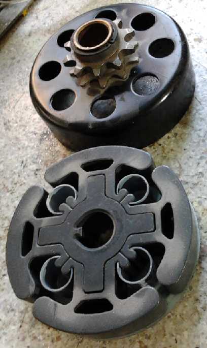
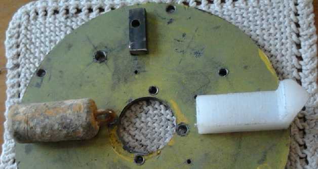
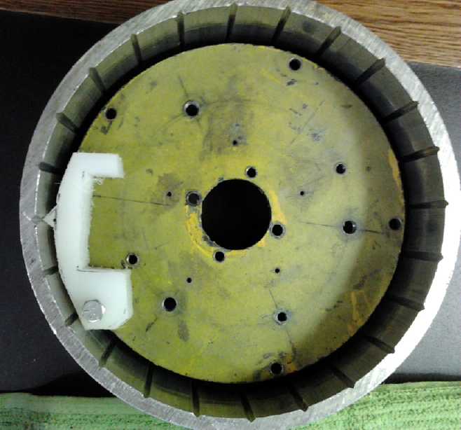
The output drum with the input disk rotor
holding the 10 shoes,
one with the first weight in it.
A side thought was how the angles might change if there
was a very short spring on each side of the hinge pin. The pin with the
weight would then be free to bounce straight inward, at 90°,
45° from the face of the slot. Compared to the input disk, it could
even bounce backward to an extent as it bounced out of the slot. The
force to the output would be a sudden impact, but the force on the
motor would be more spread out, over the compressing and decompressing
of the spring. But I decided to think about that rather
complicated-to-build idea later.
Motor & Kelly Controller
Meanwhile (9th), I looked up the Kelly BLDC motor
controller error codes to see why the motor would only run one
direction and the red LED would start repeatedly doing 2 blinks for the
other, and why it was stopping with 3 blinks at times with high load.
But the blinks didn't match what the manual said, which was that 1
initial blink, or 2, or 3, or 4, would be followed shortly by a second
set of 1 to 4 blinks. Unless it was 2-2 and 3-3 I was getting and I
hadn't noticed a different gap length between pairs. 3-3 might make
sense for "shorted throttle" for when I turned it right up... in which
case the potentiometer should be "shorted", 0 ohms. Why wouldn't that
be a normal condition? 2-2, "internal fault or +5v supply overload",
didn't seem to make sense to happen only for one direction.
I mounted the motor without the transmission in
place and tried running it again. Momentarily not thinking I turned
the control up to maximum. Sure enough, the blink had been 3-3
("throttle shorted"), then a longer gap, from turning the throttle
right up.
I wasn't thinking when I did this. Of course going to full
power also spun the unloaded motor up to a scary RPM, well over 3000 I
think and maybe over 4000. But nothing happened. At least it showed the
motor was substantially more robust than before! What I still didn't
have was the "break-out box" for the position sensors so I could easily
connect a frequency meter as a tachometer to read the actual RPM.
It still only ran one direction. The phases were indeed
wrong. The pieces of colored tape were, somehow, on the wrong wires. On
the 5th try out of 6 possibilities, it ran smoothly - more smoothly
than before - in both directions. Probably I didn't have it right to
start with. The motor originally had only done a few spins before the
magnets flew off the rotor, so the testing didn't get very far. I got
some new pieces of colored tape and put them on the appropriate wires.
I could clip all three pin sockets together on each side so it can't be
plugged in wrong, but I've found that three big "70 amp" APP connectors
in one are very hard to push together and pull apart. One at a time is
much easier, and I'm doing a lot of mounting and dismounting of the
motor in this.
But there was something very concerning: I smelled
something. It was the motor coils getting hot. With no load! With my
controllers, the motors seem to pretty much run cold. Why should they
be different with the Kelly controller? One phase seemed to be hottest,
one midway and one definitely cooler than the other two. Could it have
been heating up when the phases were hooked up wrong, and was still
hot? That would probably result in different currents between phases...
but some time had gone by since then. Or was it simply the higher
switching frequency... and, should that make a difference to the coils?
At least it meant that the controller must be delivering some very
substantial currents to the motor! It would be something to check next
time I ran it.
I took off the motor and put the clutch input plate in,
without the planets gears and pulley. That way I could see inside. I
wasn't sure the sun gear on the motor wasn't rubbing against the side
of the ring gear, but to my surprise, in fact there was about 1/4" gap.
I had cut the splined shaft a little too short last month. That
explained why the planets gear had worked itself part way off the ring
gear in spite of the thrust bearing - it wasn't pressing sideways with
unstoppable force, rather there was nothing to stop it from drifting
sideways that far. At least that now made sense and showed it wasn't a
real problem. I decided to pound the ring gear 3/16" off the end of the
shaft to effectively lengthen it. That puts the strongest part of the
sun gear center over the end gap, but it should withstand at least a
few tests.
I also discovered that the pin holding the splined shaft
centered in the transmission had unscrewed itself and fallen out. In
forward
it would try to screw itself farther in, and when I had made it I had
discounted the chance it would unscrew in the occasional bit of reverse
driving. Now all my tests were in reverse. It would have fallen out
when I took out the input rotor, as soon as I tipped it down. (Now,
where did it go? Into the lawn somewhere, most likely.) Well, it was
just a 3/8" stainless steel bolt with the head cut off. I didn't find
it so I made a
new one.
All was then ready and waiting for the next clutch
experiment.
http://www.TurquoiseEnergy.com
Victoria BC Canada