Turquoise
Energy Ltd. News #98
covering March 2016 (posted April 2nd 2016)
Victoria BC
by Craig Carmichael
www.TurquoiseEnergy.com
= www.ElectricCaik.com
= www.ElectricHubcap.com
= www.ElectricWeel.com
Features:
* Planetary Gear Torque Converter with Flywheel Drives Chevy Sprint!
(see Month in
Brief, Electric Transport)
* Nickel-Nickel Battery in Potassium Sulfate Holds Charge! (see
Month in Brief, Electricity Storage)
Month In Brief
(Project Summaries)
- The 28th - Miles Electric Cargo Truck Repair - Hands-On
Democracy Updated - a small
tilapia/aquaponics
update - Electropermanent Magnet Motors: A Whole New Field... or is it
"new"? - THREE Variable Transmissions & Sprint Car: 1. Frictionless
Centrifugal Clutch; 2. Add-On Motor & Wheel Drive; 3. Planetary
Gear Torque Converter (PGTC) with Flywheel (Now Working) -
Nickel-Nickel Battery: the simple secret! - Canada Revenue Report
(What, late again?!?)
In Passing
(Miscellaneous topics, editorial comments & opinionated rants)
- Life on Pluto - preposterous?
- In Depth
Project Reports -
Electric Transport - Electric Hubcap Motor Systems
* Lower RPM, Frictionless
Centrifugal Clutch - Making progress and tests - finally... abandoned.
* New direct-to-wheel belt drive with clutch and flywheel idea -
exploratory work.
* Planetary Gear Torque Converter (PGTC) installation and tests: it
works... Sprint to hopefully be made roadworthy with it.
Other "Green"
Electric Equipment Projects (no reports)
Electricity Generation (no reports)
Electricity Storage - Turquoise Battery
Project (NiMn, NiNi), etc.
* Nickel Foam Arrives
* Filling a nickel-nickel cell with potassium sulfate
* Making and testing a new test cell and purer potassium sulfate... It
works!
No Project Reports on: Lambda ray
converter, CNC
gardening/farming machine, Electric Weel, unipolar motor controller,
reluctance motors (will need to modify the controllers and motors for
electropermanent magnets!).
March in Brief
The 28th, A Happy Easter Monday
The month went by like most, doing this and that on the
projects amidst other things. But the 28th turned out to be a very good
day, with two positive results for things I've been trying to get
working for years. That seems like a good place to start!
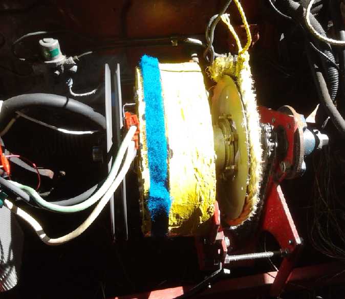
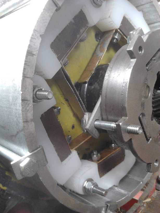
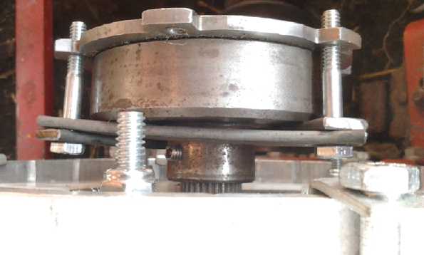
L to R -- Flywheel (heavy
cast 12" pulley); Yellow/Blue Electric Hubcap Motor;
Standoff with thrust bearing; Planet Assembly with 10" tensioning
pulley
& tensioning rope;
Ring gear (hidden) on shaft to sprocket (Chain Drive to Differential);
shaft
bearings in hub.
Upper thin pull rope is to operate tensioning system from outside car.
 That day I at
last got the Sprint car to move
somewhat
nicely, with the planetary gear torque converter transmission (PGTC -
and no
centrifugal clutch). I shot some footage to show and describe it later.
With a flywheel on the motor to boost the car into motion (and after a
pile
of
incidental things to be done) I think it just might be able to hit the
streets and I plan to put it all together.
That day I at
last got the Sprint car to move
somewhat
nicely, with the planetary gear torque converter transmission (PGTC -
and no
centrifugal clutch). I shot some footage to show and describe it later.
With a flywheel on the motor to boost the car into motion (and after a
pile
of
incidental things to be done) I think it just might be able to hit the
streets and I plan to put it all together.
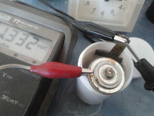 On the same
day I at last got a nickel-nickel
battery to hold its 1.25 volt charge, simply by using potassium sulfate
solution as electrolyte instead of potassium chloride. At last, with
this one little but apparently vital change, I think I just might have
a practical EV battery chemistry - one with good energy density and
exceptional current capacity!
On the same
day I at last got a nickel-nickel
battery to hold its 1.25 volt charge, simply by using potassium sulfate
solution as electrolyte instead of potassium chloride. At last, with
this one little but apparently vital change, I think I just might have
a practical EV battery chemistry - one with good energy density and
exceptional current capacity!
...and now back to a more chronological
order of events.
Miles Electric Cargo Truck Repairs
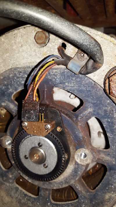 The culprit was the little brown
LED/Phototransistor assembly, here unplugged.
The culprit was the little brown
LED/Phototransistor assembly, here unplugged.
The motor is underneath the truck. Two protective covers go over
this delicate
assembly including a big metal one over the whole end of the motor.
Notwithstanding,
there was some corrosion in the threaded bolt holes, and likely inside
the reader unit.
I received the part, the
"reader" for the motor rotation
sensing, from Canadian Electric Vehicles (canev.com) on the 4th. On the
5th I installed it, reassembled enough to
have it run, drove the truck up and down the street to test it, and put
the cab seats et al back together. It ran fine and I expect its
troubles
are
over. Perhaps it's just as well I didn't know the truck had an unknown,
intermittent problem when I bought it - I probably wouldn't have and
would have missed a bargain. It's a great in-town delivery vehicle, but
I don't think it's what I want to drive for most of my driving. So I'll
consider it an investment, perhaps to be sold hopefully for a
profit some time - unless I find I'm delivering green energy products
to customers!
Hands-On Democracy - Proposals for How to Run a World
I made several improvements and extensions to my Hands
On Democracy (HandsOnDemocracy.org)
write-up
for
having
people-controlled
governments
and
voting
via
the
internet,
including
new (if vague) proposals for how a future legislature just might be
constituted and for democracy in the workplace. That makes 10 unique
proposals for improving on the way things are run today. I put in lots
of
keywords for search engines and I now leave these seeds in the lap of
the gods for interested people to find, and to plant those they may
find useful. From
experience so far I don't expect much interest before things finish
falling apart. After that people will be searching for fresh solutions
and be willing, even eager, to try them out.
A Small Tilapia/Aquaponics Update
Well, I haven't done much on this this winter. The tilapia
have been languishing in an aquarium on the floor since the old one
started leaking. This month I found a used aquarium and stand and moved
them. Hopefully sometime they'll breed again. I consider that a main
problem I had with tilapia attacking each other earlier was that all
but one seem to have been males. Now there are just three: the large
female, a smaller male, and the one male offspring that I saved when
all the rest were eaten as tiny fry, which is now almost as big as the
other male. They seem to get along fine.
I have also acquired some hydroponic/aquaponic grow beds
and I plan to place
them in the greenhouse and connect them to the goldfish pond in the
garden. All the fish waste in the pond is just growing algae, and I
can't change the water fast enough. What to plant? Let's see:
lettuce, spinach, the ubiquitous basil... what else? Greens. No beans!
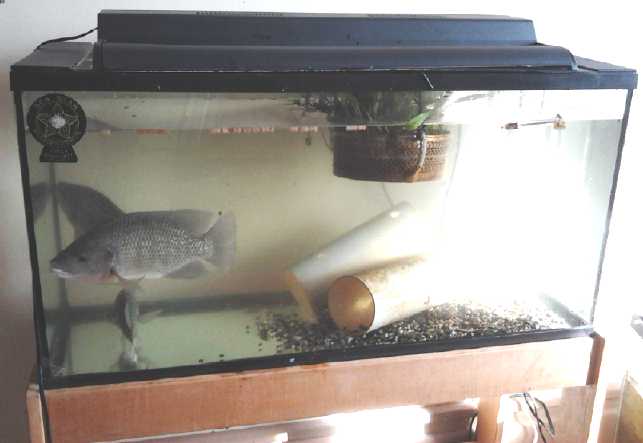 A nice 'new' 30 US gallon tank for the tilapia
"breeding colony"
A nice 'new' 30 US gallon tank for the tilapia
"breeding colony"
Electropermanent Magnet Motors: A Whole New Field - or is it
"new"?
I searched youtube, and then the web, for
"Electropermanent Magnet Motor" and "Electropermanent Motor". All I
came up with besides "Electropermanent Magnets" (not motors) was
several hits on a patent for a tiny servo motor from DARPA, developed
at MIT for microrobotics. Other than that, the only relevant hit seemed
to be something titled Turquoise Energy News #97(!), my own
last newsletter, about 40
hits down. Apparently the whole field is brand new with almost nothing
written on the web about it.
But I found one interesting development on Youtube just
before that search - I forget how I ran across it... Someone had
translated
to English a 1966 video, perhaps from a TV news show, from a German
inventor who in 1962 made a large magnet motor that turned itself. The
inventor said that the magnets were demagnetized just before they
reached the "sticky spot" (where most attempted magnet motors halt
their rotation), and remagnetized after it, and hence the motor kept
turning. How this was accomplished wasn't said, but in essence it's the
operating principle of the electropermanent magnet motor. And he did it
before there were 'supermagnets', too! (He also mentioned being
undermined and thwarted in his attempts to patent or commercialize his
machine, which he hoped would replace polluting gasoline engines.
...what a surprise!)
 On the topic of
electropermanent motors, I thought that the way to get the magnet
magnetized fastest, and hence using the least power,
would be to have the lowest inductance, so the current would rise
fastest to the critical level where it magnetizes the AlNiCo core, and
then be turned off. That would mean
the fewest turns of the heaviest wire. But at high frequencies, or in
this
case the desired very short pulse widths, there's the 'skin effect'
where most of
the current flows around the outside of the wire, and fatter wire isn't
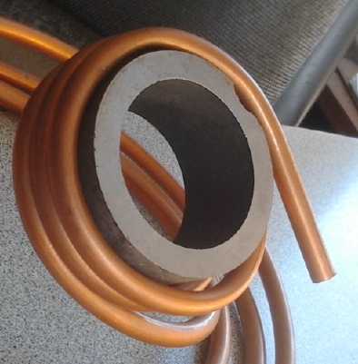
as useful as might be expected. Finally, small gauge copper pipe came
to
mind. Lots of copper, fat, and all "skin". And (perish the thought) if
it should run too hot, one could flow water/coolant right through the
conductor coil! But presumably it will use little enough electricity
that it won't get hot. On the contrary I might squash the ends and
mount some of the transistors right on the pipe - it would make a good
copper heatsink!
On the topic of
electropermanent motors, I thought that the way to get the magnet
magnetized fastest, and hence using the least power,
would be to have the lowest inductance, so the current would rise
fastest to the critical level where it magnetizes the AlNiCo core, and
then be turned off. That would mean
the fewest turns of the heaviest wire. But at high frequencies, or in
this
case the desired very short pulse widths, there's the 'skin effect'
where most of
the current flows around the outside of the wire, and fatter wire isn't
as useful as might be expected. Finally, small gauge copper pipe came
to
mind. Lots of copper, fat, and all "skin". And (perish the thought) if
it should run too hot, one could flow water/coolant right through the
conductor coil! But presumably it will use little enough electricity
that it won't get hot. On the contrary I might squash the ends and
mount some of the transistors right on the pipe - it would make a good
copper heatsink!
THREE Variable Transmissions
&
Sprint Car
1. Frictionless Centrifugal Clutch
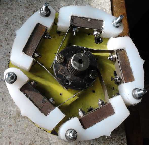
Centrifugal clutch with weighted shoes having
"V" points to click into the "V" slots
in the drum. The brass springs were much stronger than the first
thinner nickel-
brass springs. (With only enough brass for four springs, the fifth was
three of the
old ones put together.)
 I continued
working on the frictionless centrifugal clutch. I bypassed the
planetary gear assembly (Clamped two of the gears together) so it was
just the clutch in effect on the motor shaft. I put in
the weights on the shoes and ran it. The car moved once, but the torque
was really pretty feeble. And it was noisy. I put in some springs to
push the shoes outward into the "V" slots in the drum and ran a test,
but the springs bent. Then I
made stronger springs and did another test, but I still wasn't getting
much torque out of it.
I continued
working on the frictionless centrifugal clutch. I bypassed the
planetary gear assembly (Clamped two of the gears together) so it was
just the clutch in effect on the motor shaft. I put in
the weights on the shoes and ran it. The car moved once, but the torque
was really pretty feeble. And it was noisy. I put in some springs to
push the shoes outward into the "V" slots in the drum and ran a test,
but the springs bent. Then I
made stronger springs and did another test, but I still wasn't getting
much torque out of it.
By this time however the partial hits had flattened out
the "V" points in the plastic shoes, which probably contributed
considerably to poor performance,
especially on the last tries with stronger springs, when everything
finally seemed to
"clack" solidly into place as it turned.
At this point I really should have sharpened up the "V"
points and put springs on the other 5 shoes on the other side as well
and tested it again.
It might have worked a whole lot better. But it was still noisy. And by
then,
the 24th, I was thinking of other means for driving cars.
The clutch has to be workable somehow, but
apparently I don't have all the factors right. If the hits at the "V"
slots transfer more of the momentum of the motor to the drum, it pretty
much has to work.
On the 25th, having just removed the clutch assembly,
I started coming up vaguely with a new design of "V" tooth, with an
extra moving part, that would snap instantly into the slot without the
weight
having to move. But then the weight would have to bounce with it for it
to bounce out of the groove again. It seemed promising if a bit
complex, but with fresh thoughts about other types of drives, I tried
hard to shove the idea out of my mind.
2. Add-On Motor & Wheel Drive
This time, instead of either a wheel mounted motor or a
toothed belt or chain drive direct to a rear wheel, I started thinking
of a flat belt with a pivot and spring motor mounting that would allow
the belt to act as a clutch. The
clutch would be combined with a flywheel on the motor. To start the car
moving, the motor would be revved up, then the clutch pedal would be
released. As the belt engaged, the momentum of the slowing flywheel
would be transferred to getting the car wheel turning before the belt
was tight. That way, the reduction ratio
between motor and wheel could be much lower than that needed to start
the car moving with a stopped motor -- maybe 3, 4 or 5 to 1 instead of
the typical EV's 10 to 1. It could essentially start already "in second
gear", eliminating the need for "first gear". A 3 to 1 or lower ratio
would put a small car with a 3000 RPM Electric Hubcap motor up to
highway speeds. (For a rough comparison, the Nissan Leaf motor turns
over 9000 RPM on the highway, in order that it will have the high gear
ratio for starting torque.) A 5 or 6 to 1 ratio would at least allow
city
driving -- or highway driving with a high RPM reluctance motor. With
any motor and ratio, the clutch with flywheel reduces the necessary
single gear ratio and RPM at any given speed.
I started looking at pulleys for flat belts. Bandsaw
"wheels" looked flimsy. The most
promising seemed to be to make one, using a 13" O.D. PVC pipe for the
outer rim to run the belt on - and probably a double (1.5" thick)
plywood center reinforced with steel.
On the 22nd I went out and sized up the Sprint for such a
rear wheel flat belt drive motor, armed with the motor and a very short
piece of the Turquoise 13" O.D. PVC culvert pipe for which Turquoise
Energy was named. External drive would have advantages even for the
engineless Sprint: if the motor and a transmission weren't under the
hood, there was room there for most of the batteries and the spare
tire, leaving most of the car interior free for its regular uses.
I was a little disappointed with how far out the motor
would stick, 6 to 8" depending where one measured from. But it would be
down where the plastic fender was. I looked underneath the car. It
appeared that if a part of the fender was cut away, and just a small
piece of body sheet metal, there was room in this particular car to put
the motor underneath the car, with the bottom still above the wheel
rim. Only the drive belt, pulleys, and a belt guard would stick out.
That could hardly work out better!
On the 24th I did some exploratory surgery. I removed the
rear fender from the car. It looked like if I cut away some of the
plastic fender, the end of the metal bumper beneath it, and a small
area of the body below the floor, there was room to put the motor
directly behind the wheel instead of sticking out the side. I would add
a protective cover for the motor and a small
extended fender a little behind the the regular one at the right side.
 By cutting away below the top of the square
hole, the motor could be swing- and spring-mounted under
By cutting away below the top of the square
hole, the motor could be swing- and spring-mounted under
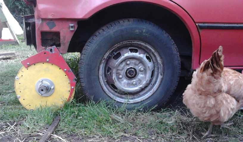
the car directly behind the wheel with the flat
clutch-belt running between them. The "culvert pipe"
outer rim of the pulley (oops, not shown) fits just
inside the rim of the wheel, and a smaller pulley
would go on the motor. But the real drive power comes from the chicken.
3. Planetary Gear Torque Converter (PGTC) with Flywheel (Now
Working)
While thinking
of the belt drive, I considered that I had
never properly tried the PGTC with a flywheel on the motor. I wanted to
do that in 2013, but I got on to clutch designs that haven't worked out
just at
that time, and I had no way then to mount a flywheel on the motor
shaft. With
a sufficient flywheel, the PGTC should work. The slipping gear can act
as a clutch as with the flat belt drive and the flywheel inertia starts
the
car
moving. Once it's in motion the torque conversion comes into effect and
will keep it going. Now the motor would need a flywheel anyway for the
belt drive, and I had extended the shaft so one could be added on the
'back' side of the motor. Plus, the Kelly BLDC motor controller will
put about 4
times the current (= 4x torque) into the motor than my controller did.
If the system was sufficiently robust - and if I pursued it - the 4 to
1 drive chain reduction to the differential could be reduced to 3 or 2
to 1 to allow higher speed driving.
On the 25th I explored this idea by removing all the extra
stuff for the centrifugal clutch and reinstalling the PGTC and motor
more or less the way it was in 2012 when it had proved it could
keep the car moving if it could be coaxed into starting in the first
place. Most of it proved easy; I still had all the pieces. It just
needed 3
small new mounting brackets. I figured that the higher current Kelly
controller and the faster spinning Electric Hubcap motor would apply
more torque
even without adding the flywheel, to get the car to start moving for
tests.
I determined that I was
going to test out both approaches. The PGTC could theoretically have
the car crawl up a very steep hill or tow a very heavy load at low
speed. But now I just wanted to prove that it works, and then maybe run
a few more ambitious tests - ultimately to take it out on quiet streets.
In the Sprint a motor system under the hood is fine. And
if an electropermanent magnet motor gives the hoped for vehicle range,
the add-on hybrid idea may become superfluous. Regardless, the
wheel-belt drive gets back to the original Electric Hubcap add-on motor
idea, plus it looks far easier to do from scratch than any other system
so far. And it has no gears that would require lubrication. This
assumes it can start the car with sufficient torque without needing two
gears - one for startup and another for higher speed driving.
The next morning (26th) I thought of, and got, a
ready-made,
perfectly balanced flywheel: a large (12", 4Kg) cast iron spoked V-belt
pulley. (45$ surely well spent.) Later I did 2 of the 3 mounting
pieces. The next day I tackled the third one, the stay for the slipping
pulley
rope. (BTW the large pulley and tensioning rope replace the steel bands
used with planetary gears on some earlier(?) transmissions.) On the
morning of the 28th I turned down the 'stand-off' for the
thrust bearing, which was a little too long for the 'new' setup. Then I
tried the whole thing out, without the flywheel. It was a little
hesitant to start the car moving, but it worked. Once moving, the front
wheel even
jumped over a 2.5" x 2.5" block of wood that was supposed to keep it
from going too far. Adding the 4Kg, 12" flywheel to the motor
will help. If still more weight of flywheel is determined to be
desirable, the store has 12" double V-belt pulleys that are even
heavier.
It was a real pleasure running it all using the 300 amp
Kelly BLDC controller, which never blew up and which can deliver much
more current to the motor than my controllers do. I guess it was worth
all that
money after all.
The basic test having been run, the question now was
whether to pursue and complete in all
details what appeared to be a workable system on the Sprint, or to take
it out and try the belt drive. I want to try the belt drive, but except
for needing another motor and controller it could almost as easily be
on a different vehicle - like my "new" 2001 Toyota Echo (replacing the
rusty 1984 Toyota Tercel wagon).
I went out and looked under the Echo, and there was in
fact more room to mount a motor directly behind the wheel than on the
Sprint, both vertical space and sufficient horizontal space in front of
the rear bumper. Only the wrap-around side of the plastic fender would
need to be cut away where the motor and belt would sit. And the car had
quite a deep trunk where batteries might be installed. Pretty much
ideal! Perhaps there are lots of cars where the motor could be fitted
underneath the rear trunk space instead of sticking out the side. (The
Tercel isn't one of them - the gas tank is in the way.)
So that's it: it'll be the PGTC with flywheel on the
Sprint. A new motor with flywheel + clutch & belt to the rear wheel
on the Echo will have to be reserved to be a later project - preferably
after a new and improved motor is developed.
On April 1st I met a Mazda RX7 aficionado. He was just
getting out of his car as I passed by and I remarked that his was a lot
shinier than my electric one. We talked a bit and he was interested in
making one of his electric, and I would love to see the parts from mine
go into a car in better condition. Depending on his mechanical skills
and leanings, perhaps I can convince him to try out a flat
belt/clutch/flywheel drive system under the hood. That would give him
more range, with less power, than using the original transmission as
mine does.
Nickel-Nickel Battery: the simple secret
On the 27th I finally got back to new chemistry batteries.
1.1 volt nickel-nickel cells seemed to be more promising in some ways
than the nickel-manganese 2.4 volt cells, but whenever I tried to make
one, there was unexpected relentless self-discharge. Perhaps 3 months
ago I thought of trying a different electrolyte instead of potassium
chloride, and I finally got around to the next choice, potassium
sulfate. It worked! The self discharge was reduced from immediate to
taking overnight. The remainder, which was pretty much similar to the
NiMn cells, is probably owing to oxygen entering the water in the open
top test cell, or because the positive side hasn't got much substance
and isn't well made, or because of contamination from the carbon rod,
which came from a chloride electrolyte dry cell.
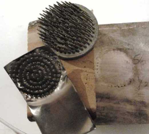 And I thought
that the old "pocket electrode" from about
1900 would be a great form for the negative electrode. But I didn't
manage to punch perforations through the cupro-nickel sheet metal
(Cu:Ni 70%:30%), which was much harder than just copper. Instead I
destroyed the pin frog I was trying to punch them with.
And I thought
that the old "pocket electrode" from about
1900 would be a great form for the negative electrode. But I didn't
manage to punch perforations through the cupro-nickel sheet metal
(Cu:Ni 70%:30%), which was much harder than just copper. Instead I
destroyed the pin frog I was trying to punch them with.
I may just end
up making them much like standard manganese-zinc dry cells. It
would be ideal if I could find cupro-nickel cans.
Canada Revenue Report (What, late
again?!?)
All well and good... Much as I prefer working on real
projects, I'd better get
started on the annual report for Canada Revenue Agency. I seem to have
been dragging this out longer and longer each year, finishing in May or
June the last couple of last years instead of in March. Considering
this brings my annual compensation, such as it is, for doing
experimental development, you'd think I'd be more enterprising about
getting it done.
In Passing
(Miscellaneous topics, editorial comments & opinionated rants)
Life on Pluto?!?
Is it even conceivable? The temperature must be
hardly 50 or 60°K even when Pluto is closest to the sun. Yet here
from
the scientists is that typical mention, stated uninterestingly and
vaguely as "dark reddish 'tholins'" -- which probably means
the same telltale spectral signature of polycyclic aromatic
hydrocarbons as has been found on several airless icy worlds of the
Jupiter and Saturn systems, on asteroid Ceres and even on an icy comet,
which seem to have organic, perhaps a sort of "crystalline",
vegetation.
Temperature regulation on airless worlds would be vastly different than
those with an atmosphere, but if such vegetation can actually grow in
such a deep freeze as Pluto, so far from the energy of the Sun, it must
live in
really slow motion.

"Pluto's surface is still geologically active and changing. At lower
right, ancient, heavily
cratered terrain on Pluto is coated with dark,
reddish tholins. At upper right, volatile ices
filling the informally
named Sputnik Planum have modified the surface, creating a chaos-
like
array of blocky mountains." (NASA/JHUAPL/SwRI)
Currency Crunch?
Around the turn of the millennium, the ever growing US
debt hit around a trillion dollars. By 2008 that grew to 8 trillion,
and it is now approaching 20 trillion. If things are to continue, in
another 8 years - even if attempts at prudence were finally to kick in
at this point - it would doubtless be at least 40 trillion. The economy
continues to decline with record bankruptcies, ever shrinking consumer
spending and real estate markets that continue to decline,
notwithstanding a few local areas of good industrial activity and real
estate investment prosperity. The middle class has lost its wealth, and
anyway an aging population doesn't need so many new things. Pensions
are being slashed and even so pension plan funds are dwindling. 30% of
Americans are having trouble paying ever increasing rents and putting
food on the table. The young and even the middle aged are moving back
in with their parents.
Where it counts the mainstream news is lies, and more lies
by selective omission of what's covered. A long time respected
journalist in Germany says the CIA has been telling everyone in Europe
what to report on and what to say for decades. Fail to comply and
you'll lose your job and never find another in the business. Think it's
better in the USA? They get people to believe the lies not by evidence
but simply by repeating them and repeating them until everyone thinks
"It must be true."
The stock markets look rosy and the price of precious
metals is low. These indicators are carefully manipulated at all costs
because they are what people usually look at to judge the health of the
economy - in a sense they are more lies. But "QE 4" - trillions and
even tens of trillions of dollars of more money printing - is probably
just around the corner, as are bank "bail-ins" and bank failures owing
to all the outstanding bad loans. Fraud is now the admitted source of
virtually all the profits of the big banks on Wall Street and in the
city of London. Other countries are starting to balk at accepting US
dollars as major payments, and are quietly trying to unload their US
treasuries holdings.
Think about it - this has gone on for a long, long time.
The numbers grow ever more ludicrous. Can they just keep growing
forever, and financial crimes be ever more egregious, as the global
economy declines and populations suffer, or is trust slowly being lost,
and finally some pivotal event will take place, after which the world
will never be the same again?
Humorous or not...
Q:
Can sheep fly? ----- A: Obviously. They travel
in flocks. (Duh!)
Why is the word "small" bigger than the word "big"? Why is "slim" wider
than "fat"?
Q: What are the three types of mammals that lay eggs?
A: The Duck-Billed Platypus, the Echidna (obviously related to each
other), and the Easter Bunny.
Newsletters Index/Highlights: http://www.TurquoiseEnergy.com/news/index.html
Construction Manuals and information:
- Electric Hubcap Family Motors - Turquoise Motor Controllers
- Preliminary Ni-Mn, Ni-Ni Battery Making book
Products Catalog
(Will accept BITCOIN digital currency)
...all at: http://www.TurquoiseEnergy.com/
(orders: e-mail craig@saers.com)
Daily
Log
(time accounting, mainly for CRA - SR & ED assessment purposes)
March 1: Took shaft encoder "reader" off
Miles electric truck for
repair. Ordered a new one. Bought steel and cut the first of 10 weights
for the clutch 10 shoes. Found a web site offering the right size and
shape of AlNiCo5 magnets.
2: Worked on February newsletter. Cut 5 more weights. Conversed with
magnet
company by e-mail.
3: Newsletter.
4: Cut remaining clutch shoe weights.
5: Finished Miles Electric Cargo Truck repair. Centrifugal Clutch
(CClutch) - Slotted the shaft
alignment pin.
6-7-8: CClutch - Drilled and coutersunk and threaded 20 holes (#10-24)
and bolted the weights to the shoes.
9-10 -
11: Installed CClutch in Sprint car & tested: Car moves! (Further
tests prove the torque is dissapointing.)
12: More CClutch stuff.
14: same.
15: Removed/bypassed PGTC section for higher RPM at clutch
16: Tested with above.
18: New design for direct wheel drive add-on for 'any' car. CClutch:
Made and attached springs on the 5 outward facing shoes.
19: Tested CClutch again. Springs didn't stay taut. Looked around for
bandsaw wheels (for wheel drive idea). Found 14" one - it looked too
flimsy for a car wheel.
20: (Sick.) Thought of better ways - better materials - for making the
car wheel pulley. 1: A solid disc of 1.5" UHMW plastic. 2: 12" PVC pipe
ring, glued to a disk of compatible plastic - or plywood.
22: Sized up Sprint car for an external wheel-belt drive system. It
looked better than expected - very feasible.
24: Tried stronger springs on centrifugal clutch. Result was
disappointing but not conclusive. Removed rear bumper to look at
possibilities of mounting motor behind rear wheel for belt drive.
25: Removed centrifugal clutch and re-installed PGTC without clutch -
some things remain to be done.
26: Continued installation.
27: Continued installation. Tried getting a nickel-nickel battery cell
working with K2SO4 electrolyte instead of KCl. That seems to be the key!
28: Finished installation and tested it. Car moved well enough going
forward but poorly going backward. (Still needs flywheel, etc.) Made
nickel negative electrode and nickel hydroxide positive, immersed in
small jar of K2SO4. Worked well with low self discharge (compared to
most of my experiments). Probably just needs a 'sealed' cell with
properly made electrodes to have a practical, economical and
'everlasting' battery.
29: Clamped down wires and fitted flywheel. Shaft needs a keyway slot.
Did some charging and discharging of the NiNi battery.
30: Tested PGTC variable transmission with flywheel. It moved the car.
31: Worked on this newsletter.
Electric
Hubcap
Motor
Systems
-
Electric
Transport
Electric
Hubcap motor, Chevy Sprint & Variable Transmission
The Frictionless Centrifugal Clutch
Here is a theoretical thought to start with: It has always
seemed to me that the frictionless centrifugal clutch should act as a
torque converter by itself. If it did it could be ideal because no
manual clutch or gear shifting would be required.
Power = torque * speed.
The speed of the motor may be 1000 RPM, and its torque may
be 10 foot-pounds. If the speed of the car is such that the clutch
output drum is turning 250 RPM, and if frictional losses are small,
where is the motor's power going if not to the clutch drum? If the full
power is being output, the torque on the drum must then be 40
foot-pounds. (And with the 4 to 1 chain reduction, 160 foot-pounds at
the wheels.)
OTOH, the impacts of the shoe points bounce the shoes
inward. The angle of bounce to the drum is around 45°, not straight
on. That would indicate that the moment of the pulse transfers the sine
of 45° times the input energy, or .707, or 28.28 foot pounds. Is
the rest of the energy wasted in flailing the weighted shoes around? Or
is it just energy the motor doesn't supply? It seems likely it's the
latter. In that case, the motor is still speeding up - it isn't at
equilibrium yet. Anyway, even 28 foot-pounds is still more torque than
the motor has by itself, and it's still a torque converter.
Work
On the 5th I thought of how the 3/8" shaft alignment pin had unscrewed
itself and fallen out. (It was eventually found on the lawn.) After
making a new one including turning the hex head off the bolt with a
lathe to leave the exact diameter at the outer end, I cut a slot in the
end with the angle grinder so it could be more forcefully screwed into
the drum end with a slot screwdriver, to hopefully prevent repetition
of the problem.
On the 4th I
finished cutting the 100g steel weights for the UHMW shoes. On the 5th,
7th and 8th I drilled and threaded all the holes for #10-24 machine
screws, and bolted the weights to the shoes. I countersank the (pan)
heads to make sure they wouldn't hit the aluminum rim.
After making the first four went fine on the 6th, I
drilled
holes in the rest on the 7th, and on the 8th trying to finish up they
started being troublesome for no apparent reason. The machine screws
went in effortlessly to a certain point, to where they just started to
protrude out the other side. Then they would suddenly jam and neither
go in farther not come out easily again, including not screwing out
easily where they had easily screwed in - it was a fight nearly all the
way back out, holding and turning the bolt head with vicegrips. The
threads were damaged when they came out. One snapped off in the hole
with nothing to grab on either end. I had to drill it out, the whole
bolt. I managed to re-thread the hole and save the weight. But I'm not
sure it was worth it. One starts to think "I should be done by now.
Instead every piece is fighting back." It turned out the #10-24 tap was
to blame. I had bought a new one on the 7th for a spare. I tracked it
down (still in the car) and looked at both of them under a strong
magnifying glass. The old one was dull. The sharp triangular thread
ridges on the new one, on the old one near the end were worn down to
semicircles. Since the metal was 5/8" thick, not enough good tap came
out the far side even when I screwed it all the way in. In the most
dull area near the end, it didn't thread the piece to a workable
thickness - just to enough so that the screw jammed at the last turn or
two. Running the tap through again didn't help. (If I had put the tap
in from the other side, it would have reamed it out enough.) Why did
the first four go fine? Anyway I used the new tap and the rest of the
job went
smoothly and quickly.
I bolted the weighted shoes onto the disk rotor,
and it was all ready to reassemble and try out in the car. I finally
got it installed on the 11th and turned on the power. I tried having
the car go forward... and it went! I pulled out my cell fone and set it
on
camcorder and tried again. It went even better. In fact, it seemed
pretty good. When I tried to go backward, the planets assembly pushed
out - I had forgotten to install the thrust bearing piece to prevent
that. I got a video of that, but one press on the wrong button on the
cell fone exits the camcorder mode without saving the video. DON'T HIT
THE BIG BUTTON IN THE MIDDLE! ...or accidentally touch any of the three
buttons below the screen!
...hit only that little button with the square, off in the corner of
the
display! In total I've
only successfully made 3 or 4 videos on the cell fone, but I've lost
several when I went to stop recording. So as a
camcorder, it's a very frustrating device.
I digress... Later I installed the thrust bearing, but I
couldn't get the car to back up... and barely to go forward. I had the
car on planks so it wouldn't take much to move it. According to the
torque wrench, about 40 foot pounds at the wheel to back up, and 30-40
to go
forward. Assuming it didn't have a lot to spare the first couple of
times, and since it hardly moved later, it was probably doing under 40
foot-pounds - With the 4 to 1 chain drive, just 10 at the clutch. And
after a couple of minutes of hardly
moving, the motor
coils were quite hot.
In the moves, sometimes the slipping pulley of the
planetary gear torque converter turned slowly, sometimes it stayed put.
If I let it slip more, there was less torque to the clutch and the car
didn't move - only the slipping pulley and gear spun.
So the success seemed pretty minimal. But I know that to
move the car by
turning the clutch drum by hand, takes a lot of force on the drum. If
it doesn't get around 200 foot-pounds to the wheels, or 50 at the
clutch drum, it won't be hitting the street. Was there something I just
wasn't getting right in all this, or was there something I could adjust
or change to get more torque?
Just as it was getting dark, I remembered I could put the
torque wrench on the clutch output shaft instead of on the wheel. I
went out again and tried it. This time I noticed that the slipping
pulley tensioning rope was out of place underneath, off the pulley. It
had caught a bolt head on the clutch drum. Small wonder the drum
wouldn't turn and the car wouldn't move! I was glad to discover that
perhaps my whole approach wasn't faulty after all. Perhaps the wheels
were getting at least 60 to 80 foot-pounds after all?, as it had seemed
to be on the first tries.
The next day (12th) I got the rope straightened out and
tried again. Results were still pretty dismal - the car only moved if
it was about ready to roll in the proper direction by itself. I decided
it was time to charge the batteries. After a number of tests, they were
probably getting down, limiting power to the motor. And then I could
jack up one front wheel and see how much torque it was really getting
by putting the torque wrench onto it. Or maybe just put it on the drum
shaft - test it there and multiply by 4.
Another thing was that the planetary gear had a built-in
reduction of about (as I recall) 1.8 to 1. So if the motor was turning
2000 RPM, the input to the clutch would only be doing 1111 RPM. And if
the planetary gear torque converter was slipping, increasing the torque
coming from the converter, that would merely further reduce the RPM to
the clutch and hence its driving force.
It was a concern I'd had from the start, that the clutch
would be turning too slowly to provide sufficient torque to drive the
drum and the car. Perhaps now that it was close to working, providing
at least some torque, it would be advantageous to try out the
centrifugal clutch as the torque converter, and eliminate the planetary
gear assembly altogether? The RPM would be higher and so the clutch
would engage more strongly.
This could be done _relatively_ easily, by removing the
motor's extension mountings and changing the motor shaft to one without
the sun gear pressed onto the end, and cut to the right length to put
the clutch input disk directly on it. Then the RPM would be the motor
RPM, and there'd be no complications in between. *IF* I was right about
the clutch acting as a torque converter.
Soon I thought of a much easier way to test the idea: take
off the slipping pulley and jam something in the planetary gears so
they would all turn together on the motor shaft. Meanwhile, the day was
done, and only one battery was almost charged. They must have been
getting rather low. I decided to keep the video on hold for now.
 On the 14th I
did as above - I put some washers into the
planetary gear to jam it. When I started the motor, they immediately
fell out and the planets
assembly shifted over toward the motor. (Again I had left out the
thrust bearing, this time thinking it would be unneeded.) Maybe if I'd
tried it in
reverse? On the 15th I cut and drilled three pieces of light steel bar
and bolted them to form a triangle so as to press the planets and ring
gear tightly together. On
the 16th (much nicer weather) I put it together and tried it in the
car. The motor (directly turning the clutch input disk with the shoes)
spun mightily at a pretty high speed, but there still wasn't much
torque. The car would only move if carefully placed so it was almost
ready to start rolling by itself. My feeling is still that the
potential is there, but that it still didn't have sufficient coupling
between the input disk and output drum of the clutch. If it had loaded
down the motor better, and that load had transferred the force to the
wheels, it would have worked. To put the car on the road, it'll need
something like 10 times as much output torque. It seems a tall order,
but I think it's there. Somewhere!
On the 14th I
did as above - I put some washers into the
planetary gear to jam it. When I started the motor, they immediately
fell out and the planets
assembly shifted over toward the motor. (Again I had left out the
thrust bearing, this time thinking it would be unneeded.) Maybe if I'd
tried it in
reverse? On the 15th I cut and drilled three pieces of light steel bar
and bolted them to form a triangle so as to press the planets and ring
gear tightly together. On
the 16th (much nicer weather) I put it together and tried it in the
car. The motor (directly turning the clutch input disk with the shoes)
spun mightily at a pretty high speed, but there still wasn't much
torque. The car would only move if carefully placed so it was almost
ready to start rolling by itself. My feeling is still that the
potential is there, but that it still didn't have sufficient coupling
between the input disk and output drum of the clutch. If it had loaded
down the motor better, and that load had transferred the force to the
wheels, it would have worked. To put the car on the road, it'll need
something like 10 times as much output torque. It seems a tall order,
but I think it's there. Somewhere!
One good thing noticed in
the testing (with a new
single-unit DC
clamp-on ampmeter making it easy to measure): The 300 amp Kelly BLDC
motor controller was
delivering up to 150 or 160 battery amps to the motor when I turned
everything right up, and everything worked fine. That's double the best
I was able to squeeze out of my own controllers without them going up
in smoke - and mostly they fried with less so call it 4 times.
Everything worked fine.
That made all the testing I did much
simpler - and probably made the expense and time of buying and setting
up the controller worthwhile. Delivering all that current, the
batteries would have dropped to well below 12 volts - we'll say 11.1
for the math. 150 amps * 33.3 volts is about 5000 watts. Judging by the
rapid heat buildup in the coils, my estimated nominal rating of 7200
watts for Electric Hubcap motors might be overoptimistic. OTOH, this
motor has pretty small exit vent holes in the rotor side face, which
could (and apparently should) be enlarged to improve air flow. And
certainly the Electric Caik motor hardly even got warm at 1200-1500
watts on the water, translating to 1800-2250 W for "hardly warm" for
the larger Hubcap
size.
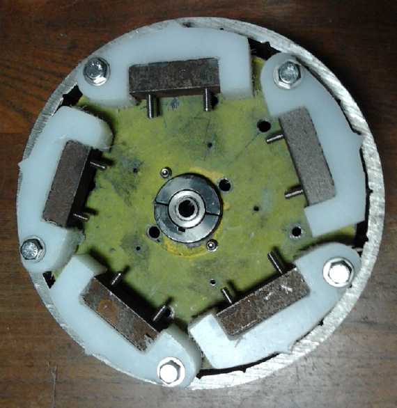 Inner/Drum side
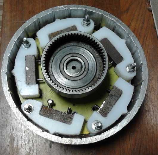 Outer/Gear side
Something else to be addressed if and once
it's working is that it's rather noisy. Gluing some chunks of rubbery
stuff onto the outside of the drum like they do to keep car body sheet
metal parts from vibrating would probably dampen the noise to
acceptable
levels.
Meanwhile... there's getting it working. There
were
at least a couple more things I could think of to try. One was to put
springs on the shoes, to force the "V" toes to spring outward into the
"V" slots in the drum instead of just using centrifugal force to have
them go in at a tangent. With the tangent, such a small bit of the
'toe' goes into the slot that the tip of the plastic "V" point is
rapidly getting worn off. With springs pushing them in, a much broader
face area would hit (greatly reducing wear), and the bounce angle would
be better. The weights would go from springing outward to reflecting
inward, a
much more substantial bounce with more 'hammer' energy to push the
drum. I think the wear on the plastic will prove to be something of a
'switch'. If the force per unit area is below a critical point, wear
should be very slow. If it's above that stress, the points will quickly
wear off, as is presently being seen. It's like, depending on a small
critical temperature
difference, water is either frozen solid or is thin liquid. There is no
range where it's like
molasses or like pliable putty.
Another way to achieve some of that would be to widen the
"V" slots. Then the 'toes' would enter deeper into the slots just from
the tangent centrifugal entry. But I'm not sure that would be enough of
a difference, and the weights still wouldn't be pushed out rapidly like
with springs.
Still another way to change things would be to change the
size or configuration of the shoes or the position of the 'toe' in the
shoe. For example, if the toe is 1/2 way between the hinge pin and the
weight, the weight has to bounce twice as far, and hence at twice the
speed. This should mean 4 times as much force involved. (e = 1/2 m * V^2.)
But these are all just ideas. What to actually try...? Or
is there something that is obviously intrinsically superior
in theory, something that I can say "Aha! This would surely do it!"?
Nothing came to mind.
 That evening I
came up with a pretty simple way to attach
leaf springs to the shoes on one side, springing them against the SDS
bushing in the center. With a small modification it could work on the
other side too, but 5 springs should be enough to tell if there's any
major improvement. The following evening (18th) I made them and bolted
them on.
That evening I
came up with a pretty simple way to attach
leaf springs to the shoes on one side, springing them against the SDS
bushing in the center. With a small modification it could work on the
other side too, but 5 springs should be enough to tell if there's any
major improvement. The following evening (18th) I made them and bolted
them on.
On inserting the disk the next day, I found that the
springs were loose. I took it out, bent them over a little farther to
about 90°, and put it back in. Now they had some tension, but it
didn't seem like very much. I tried running it, but there still wasn't
much torque. Seemingly it loaded down the motor a little more, because
instead of 150-160 amps, the motor drew up to 170-180 amps from the
battery. (I even saw "190" and "200" flash by at one point.)
As another side note 200 amps is my nominal maximum
current for the Electric Hubcap motors -- nominally, 200A @ 36V or
7200W. But the coils got hot pretty fast. And for all that power - no
real torque.
I started thinking I was doing far better with the
slipping planetary gear in 2012 (TE News #56) -- except for the fact
that the car had to be already moving before it would work. I thought
more and more that the most practical way to get that system to work
would be to have a big flywheel on the motor shaft, the inertia
of which could be used to initially get the car moving.
When I took it apart again, I discovered the springs were
bent back to almost the same angle as the first time. So they weren't
doing much good. (Maybe about 180 over 150 amps or 20% improvement?)
Evidently my nickel-brass metal, tho squashed through the jewelers
rolling mill a few times to "temper" the pieces, wasn't very tempered
and preferred to deform rather than spring back very far. They weren't
good enough - rats! Here is a place that regular brass seems superior -
I know I've had better results than this using it for springs.
I was about ready to make
some brass springs, but right at
this point, I started thinking other thoughts about how to push the
car. The flywheel idea I should have tried in 2013, but I thought a
clutch would
be better. The other sprang from newer ideas that have
been brewing in my mind about how to mount a wheel motor using a belt
drive. I started to think that both would work, and that (at least) the
wheel drive should be better than the centrifugal clutch.
Within a week I made up my mind to quit the noisy and so
far frustrating centrifugal clutch project. But since it was all set
up, it seemed silly not to do one more work session and try stronger
springs. On the 24th I made 4 of them from a thick piece of brass. The
brass
springs were much harder (after squashing the sheet metal to temper it,
it was very hard cutting it with the tinsnips), and it was thicker
metal too. When I put it all together and tried it, it seemed to work a
little better at first. It seemed more robust. But by now, _presumably_
mainly because of the earlier abuses with no springs or weak springs in
the shoes, the points were about worn off the shoes, so there still
weren't two flat surfaces hitting each other. The "V" point snapping
into the "V" groove was only a flat bottomed bump. I suspect that was
now a major part of the problem. I could probably have resharpened them
with a dremmel tool, but even so the action seemed pretty
disappointing, and if I wasn't going to use it anyway, why bother? I am
by no means convinced that it won't work, and I probably should have
tried sharpening the points and putting good springs on both sides.
But I started to think the belt drive
should be better, and at least reasonably easy to make.
New Design for
Direct-to-Wheel Belt Drive
Rick Linden got an elevator motor to use for a
generator for his floating hydro power project. The Electric Weel just
didn't have enough electromagnetic coupling unless it was made into an
'active'
generator by using a motor controller in a 'regenerative braking' mode.
The voltage and current output were both lower than I expected. The
elevator motor, also a permanent magnet "BLDC" motor, seems like the
ideal
unit, providing one volt per RPM, and if an output is shorted, it's
amazingly difficult to turn at all.
My thoughts returned to flat belt
drives for this. Then they wandered back to belt drives for a car
wheel. On the on the morning of the 18th I thought of another new
design, which seems even better than the one I proposed in TE News #86
and #91. Again a pulley is attached directly to the center of
the wheel, bolted on with the extended lug nuts.
But this time it's a flat belt pulley, or poly-V. This has
an advantage over toothed belts in that it can be slipped to act as a
clutch. Then a smaller motor with a flywheel, with a smaller pulley
reduction ratio, can be revved up to some
RPM before trying to start the car moving. The energy stored in the
flywheel will budge the car and start it moving as the clutch is
engaged. Once the car is moving, even a few kilometers per hour, it
needs a much lesser 'gear' reduction ratio than it would starting from
a stop with a
stopped motor. (The motor rotor could be made of thicker steel for a
flywheel. If that is insufficient, an external flywheel may be needed
or may be more practical.)
Again the motor is mounted in line, somewhere horizontally
behind the wheel. But it is "hung" from a fat hinge pin attached to the
car
body or frame, which holds it rigidly from twisting in any direction,
but which allows the motor to pivot back and forth, toward or away from
the wheel. A stiff spring pushing the motor backward tensions the belt
between the motor and the wheel. (The pin might go through the body
panel into the car at the cargo space floor, and could extend any
length for strength and rigidity, even across the whole width of the
car if desired, to be clamped at both ends.)
Mounted on the pulley on the wheel is a bearing with a
short shaft holding a
small stationary (non-turning) plate that allows attachment of the
clutch cable sheath and a light safety cover over the belt and pulleys.
The pulley with its light attachments are the only extra unsprung
weight on the wheel - it's ideal.
With the clutch cable body attached at the wheel, pulling
the cable pulls the motor toward the wheel to loosen the belt.
This time, there is no rigid bar holding the motor at a
specific distance from the wheel to tension the toothed belt. Between
the motor and the wheel are just the belt, the clutch cable, and the
light safety cover.
Let's say having the clutch and flywheel allows us to use
a 5 to 1 pulley speed reduction, eg, a 2.4" pulley on the motor and a
12" pulley on the car wheel. This is half of a typical 10 to 1
reduction for an electric vehicle motor. For the average 13" small car
wheel doing 10 RPM per each kilometer per hour, and the improved
Electric Hubcap motor now rated for 3000 RPM instead of 2000, we then
have (3000/5)/10=60 Km/Hr maximum speed. Above that speed one would
have to run on gas and have some mechanism to definitely disengage the
belt, preferably at the wheel. If the ratio could be reduced to 3 to 1,
the limit would be 100 Km/Hr (62 Miles/Hr), and one might just accept
this as top speed for all driving. The motor would need 2/3 more torque.
Theoretically I should be able to put 200 amps into
Electric Hubcap motors, but my controllers don't seem to have 1/2 of
that. In tests on the Sprint with the Kelly controller so far I've seen
up to around 150 amps, and it seemed to me from earlier tests that the
motor produced about 1.5 foot-pounds per 10 amps, so 22.5 foot-pounds
with 150 amps. 6 to 1 ratio (135 foot-pounds at the wheel, 50 Km/Hr
max) or 5 to 1 (111 FP, 60 KPH) seems more likely to be practical than
3 to 1 (67 FP, 100 KPH).
Of course two motors, one on each rear wheel, would
improve the equation considerably. So would a reluctance motor that
could do 2 or 3 times the RPM with similar torque, since higher ratios
then wouldn't mean limiting the top speed. The electro-permanent magnet
motor is a wild card, since I don't know how much maximum torque is
attainable. It depends on the strength of the fully magnetized AlNiCo 5
magnets compared to "fully energized" (say 150 to 200 amps from the
battery)
electromagnets. As shipped they certainly don't seem as strong as
supermagnets.
Thinking of where one might get a flat belt pulley for the
wheel, at first I thought of an old machine sitting outside a brewery.
I wrote an e-mail to the owner to see if he would sell it, but just as
I finished writing it, thinking of how to give the pulley traction, I
thought of how bandsaw pulleys give traction with a polyurethane
"tire", which also gives the pulley the right profile for a flat
band/belt and... wait a minute, why not a bandsaw pulley? They're
probably available in various diameters and widths. How about one
something like 12" diameter and 1.5" wide or wider, perhaps made for a
bandsaw resaw or sawmill? There were some "bandsaw wheels" on e-bay if
I can't find one closer to home. I didn't send the e-mail.
Considering that the installation plan looks like the
simplest one ever, and how easy it would be to change ratios to find
the most
practical, or to change motors as different motors and controllers were
developed or became available, this seems like a fabulous way to do it.
If I wasn't in the middle of trying to do the Spint car with the
centrifugal clutch, I would unhesitatingly start on this plan, with the
Electric Hubcap motor and the Kelly BLDC controller, which are working
well together now. Even on the Sprint, it would be great to
have the drive external and the most of the space under the hood left
vacant for batteries. Then, weight balance permitting, the whole rest
of the car could be kept "as is" for its regular passenger and cargo
uses. (Maybe the spare tire and 2 of the 3 batteries up front, and one
battery at the back in the spare tire space.)
On the 19th I asked at a tool store. They had a 14"
Delta(?) bandsaw wheel. Like the ones in my own bandsaw, it was
aluminum and looked too flimsy to put on a car wheel. But seen without
the tire, there was a 1" wide indented area between the outside ridges,
and it was bulged - slightly barrel shaped. I had thought it was the
polyurethane "tire" that had the bulge, now I realize that it's the
pulley itself that's bulged and the "tire" is flat urethane, simply
stretched over it. I could make a pulley the correct shape, something
like the brewery's but custom made, and order available "tires" to fit
it.
Here's one idea: draw up a circular steel plate for a
center (3/16" thick?) and have it cut out at an abrasive waterjet
place. Get some 1.5" wide by 1/4" thick bar stock and use a roller to
bend it to the outer curve to fit around the disk. Weld it on all
around. Using a large metal lathe trim it to true and round while also
shaping the surface: the 'barrel' shape with an edge on each side to
hold the non-skid urethane 'tire'. As a refinement, one could use
fairly thin plate for the disk (1/8"? 3/32"?), and weld a thicker but
smaller diameter disk having the same patterns to it to reinforce the
center area. That should minimize weight.
Or one might use thicker pieces of aluminum to make the
same thing. It would be lighter, faster (cheaper) to waterjet cut, and
surely easier on the lathe. I've recently heard about "aluminum
brazing" which might work well, or I might just give the job to a
welder who's familiar with aluminum welding and has the equipment.
Hmm... another option could be to have the disk and two outside rings
cut on the waterjet, totaling 1.5" width. Make them so they just bolt
together, then trim the rim on the lathe. No welding required. Darn,
soon I thought of more and more ways it might be done. (Not even to
mention making it out of wood or plywood on a wood lathe!)
On the 20th I thought of a couple more ways yet to make
the pulley. The first would be to take a 1.5" thick piece of UHMW
polyethylene and make a whole one piece wheel. A 12" pulley would
weight ~2.9Kg, but some could be milled out for "spokes" or other
pattern cutouts or thinnings to lighten it.
The second would be to use a piece of glueable PVC (or
???) plastic pipe, juat 1.5" long, and make an inner disk of the same
material. After gluing the pieces together, this would of course be
shaped and trued on the lathe. (By gosh, I even still have the
turquoisy colored 12" PVC culvert pipe section for which Turquoise
Energy was named!) That might not even need a "tire" on it for
traction. (The UHMW definitely would.) It might even be just about the
right texture for the clutch action.
 On the 22nd I
sized up the Sprint for this potential idea.
The only really tricky part would be the mounting of the motor. It
looked like it would stick out farther than I expected. It could
probably be
made acceptable with appropriate cowlings, but you wouldn't want it to
hit any chickens while driving along the road.
On the 22nd I
sized up the Sprint for this potential idea.
The only really tricky part would be the mounting of the motor. It
looked like it would stick out farther than I expected. It could
probably be
made acceptable with appropriate cowlings, but you wouldn't want it to
hit any chickens while driving along the road.
But it looked like on this
particular car, one might reverse the motor and put it under the car
body, straight behind the wheel and clearing it by a couple of inches.
That would take it to the rear fender, some of which might have to be
cut away, but only a small piece of body sheet metal would have to be
removed so that the bottom of the motor would be above the wheel rims.
Aside from being a legal requirement, you don't want your car skidding
along on the motor if you get a flat tire!
On the 24th I did an exploratory surgery, removing the
rear fender - 2 pieces of plastic with a solid foam core. Aside from a
couple of rusted, very recessed bolts that I had to drill out, it all
came apart readily in a couple of hours. There was both more body metal
in the way of the motor than expected and less. Less because much of it
was rusted out anyway. It was rustier than I had expected. There was a
metal bumper under the plastic, which would need about 3" cut off the
end to fit the motor. But all the bolts were farther toward center so
it wouldn't hurt anything. The motor would be at the very back of the
car. I would want to put an additional bumper of some sort behind it.
Just a few inches. And a very good guard to keep out dirt flung up by
the wheel.
The other chicken inspecting the behind-wheel
motor
& belt drive arrangement.
The corner of the body would be cut away at the top of the rectangular
hole - just under the cargo floor.
The Planetary
Gear Torque Converter (PGTC)... again? --- Now Working!
Another thought arose from
consideration of the slipping belt clutch with flywheel... The reason
the PGTC wasn't a go in 2012 was because it wouldn't start the car
moving - it seemed to have no conversion effect until it was. I made a
serious mistake after that (TE News #69) in putting a flywheel on the
slipping gear instead of on the motor (that being much easier to
accomplish the way it was set up), thinking that a flywheel would start
everything moving and that it didn't matter which of the two moving
gears it was on. (A manual clutch I tried to install around the same
time also might have worked, but with trying to fit it into a limited
space it was poorly made, flimsy, and not surprisingly the belt just
slipped off it.)
As with the slipping belt clutch, flywheel momentum - on
the motor shaft - could initially boost the car into motion. Once it
was in motion, the torque converter variable reduction could easily
keep it moving.
Now if I wanted to try this plan again I had (a) the
realization that the flywheel has to be on the motor shaft (duh!), (b)
the idea of adding a second steel rotor inside the motor as a flywheel,
(c) a motor shaft that I put in later with extra length sticking out
the 'back' side of the motor - just for possibly mounting a flywheel,
(d) a motor that can now spin up safely to a substantially higher RPM,
and (e) the Kelly 300 amp motor controller that can put much more
torque to the motor. In fact, at least on smooth level ground the car
would surely start moving with its current gearing even without the
torque converter action.
With it, it should be able to get going anywhere, although
I fear the PGTC slipping gear as a clutch will probably have muddy
action compared to the slipping belt on the wheel. On the plus side, it
drives both front wheels through the original differential and CV drive
shafts. The belt-to-wheel will only drive one rear wheel, making it
best a "pavement only" vehicle, the antithesis of a four wheel drive.
I hadn't thrown out the old PGTC shaft to potentially
reconnect it all the way it was. Given that I needed to add a flywheel
anyway to try the slipping belt idea, the rest should now be very easy
to try out, except perhaps for changing the tensioning rope position
back to where it was then, fitting the thrust bearing, and a couple of
altered mounting issues. If those didn't look too bad, it might be
worth doing at this point just to say "it works". If I was going to try
it, it should be done first, while the motor controller was still under
the hood and the transmission body was still installed and connecting
the front wheel drive shafts.
At first, on the 24th, I decided not to bother. The flat
belt on the wheel seemed promising, and it would be quite simple to do
from scratch, and it
doesn't have gears that need lubrication. Plus, it allows essentially
the original Electric Hubcap "add-on motor" plan to "hybridize" a
regular gas car without removing the engine et al. For these reasons,
it's probably worth building and testing the belt-to-wheel system even
if the PGTC under the hood did provide a working car.
But on the 25th I removed all the extra stuff for the
centrifugal clutch and reinstalled it more or less the way it was in
2012 when the PGTC had proved it could keep the car moving if it could
be coaxed into starting in the first place. It proved quite easy
because I still had all the pieces, and it looked like it would all
work again. The slipping gear tensioning rope looked like it could be
persuaded to move over the required couple of inches, tho a new center
stay would need to be mounted. I needed to make that and 2 small
mounting brackets before I could try it out. I figured that the higher
current Kelly controller could get the motor spinning faster and apply
more torque even without adding a flywheel, to get the car to start
moving.
Then the next morning (26th) I realized there was a
simple, balanced flywheel readily available: Princess Auto had small
and large cast iron V-belt pulleys, single and double, with an "H"
bushing center, which bushing could be had for my 1" motor shaft. If
one 10" or 12" pulley wasn't enough, I could put two on, or a double
one. I went out there and found mostly empty shelves. The only choices
above 6" were a spoked 12" and a double spoked 12". I took the single,
which proved to be 4Kg. It was 45$. With this large, heavy piece
spinning at high speed, I could wish the motor had a thicker shaft. At
least it doesn't have a V-belt attached, stressing it to one side!
That afternoon I made 2 little mounting pieces, and on the
27th the rope stay. When I tried to put the motor on, I found the
thrust bearing stand-off was about 3/8" too long. No run test today! I
started to think it would be better if the stand-off was made from 2
pieces of 'telescoping' pipe. Then it could be fitted to length during
installation and set screws tightened. Was it possible I could find
such a piece of pipe to fit the one the stand-off was made from, which
in turn fit the bearing plate 'washer' piece?
But the easy way was just to trim off 3/8". I trimmed off
1/4" or so on the morning of the 28th. It still didn't quite fit, but I
saw that I could just adjust the shaft over 1/8 or 1/4" at this point,
and I did so. It was now ready to try out. The car went forward nicely
until it hit a 2.5" x 2.5" block of wood. I didn't realize it had and
was momentarily disappointed that it seemed to have stopped for
nothing. It didn't work very well backward, but on the next forward try
it jumped over the block and bumped into my tool stand before I got it
stopped.
There are still issues
before the car hits the streets.
The revved up motor lost much of its speed before the car would get
going fast enough for the torque converter to take over. Installing the
flywheel should solve that. The motor's wires will all have to
be tied or clamped out of the way so they don't hit it. (now done.)
The slipping pulley got rather warm. I'm starting to see
the slipping pulley PGTC as a low speed device just to get the car
moving, with the slip to be ended as the vehicle crosses maybe 10
Km/hr. Unlike in the cool-running Electric Caik outboard, the motor
also got more than warm. I need to drill out the vent holes in the end
cover to a larger size and probably add some more of them to get more
air flowing through it. Heat may become a major issue in running actual
travel trips on the street. I'll leave it at larger vent holes for now.
The chain drive reduction ratio will have to be reduced from 4 to 1 to
3 to 1 or less even for city driving to keep the RPM.s down - I trust
the car can still get going.
The decision now had to be taken whether to finish the car
with the PGTC, which now with the flywheel at least looks like it will
work in town, or to dismantle everything and try the belt drive.
I really like the belt drive plan. OTOH, it hasn't been
tested or proven yet. What if there are unforeseen difficulties? What
if the required reduction ratios prove disappointing? Perhaps better to
go with something that already seems to be working. And doing the PGTC
on the Sprint isn't necessarily incompatible with trying out the belt
drive on some other vehicle - even on a gas car to turn it into a
hybrid per the original plan. As it happens my 'new' 2001 Echo has lots
of room for the motor behind the right rear wheel - much more than the
Sprint. And perhaps it could be in conjunction with a new
electropermanent magnet motor, either of the Electric Hubcap BLDC4-3
type or the ARM reluctance motor type.
So PGTC it is. The next step will be to connect the gas pedal
and inside Fwd-Off-Rev switch so the car can be run from inside instead
of from the test control outside.
 I clamped the wires to the motor so they
wouldn't hit the flywheel.
I clamped the wires to the motor so they
wouldn't hit the flywheel.
 Then I mounted the flywheel. But I'm not happy
with just a taper lock shaft bushing friction fit.
Then I mounted the flywheel. But I'm not happy
with just a taper lock shaft bushing friction fit.
Rather than remove and disassemble the motor, I plan to hack a keyslot
in the shaft
with the angle grinder in situ. (That's better than not having one!)
There may be just enough length to put a shaft collar on the end for
more safety.
(Or maybe drill a hole and put a bolt through the end of the shaft.)
Turquoise
Battery
Project
-
New
Chemistry
Battery
Making
Why Nickel-Nickel?
Why do I think NiNi in salt will be a better battery than
NiMn in salt, when NiMn charges to 2.6 volts and NiNi to only 1.3
volts? The nickel manganate posode is the same for both cells.
First, there's the voltage itself, for all that we all
want the most volts per cell. It was tricky getting manganese to hold
it's -1.5 volt charge, and tricky finding an electrode conductor that
wouldn't bubble hydrogen at that voltage. I'm not saying it can't be
done. Then, at that high voltage, one is bound to have considerable
outgassing during charging regardless. Dry cells would be out, and the
cell would surely need occasional refilling - more than lead-acid.
Instead, the voltage of the nickel negode is so low there should never
be hydrogen outgassing unless it's overcharged, and having it positive
limited should fix that. Dry cells are thus easily done.
Then there's the characteristics of the metal. The
manganese didn't seem all that conductive (hence the zinc powder
additive), and I'm suspicious that it will turn from micro-crystals
into larger crystals during charging - phenomena that plague
nickel-iron cells and reduce the effective amp-hours per kilogram. I
could be wrong. Metallic nickel OTOH is very conductive and it seems to
me unlikely it will clump up.
Then there's practicalities. Cupro-nickel backing and
terminal connector sheets, nickel foam, and various nickel powders, are
all readily available once one locates sources. This makes for easily
made electrodes. If sheet metal and foam are available in manganese
metal, they won't contain the hydrogen overvoltage trace additive
ingredients that I discovered (antimony sulfide and zirconium
silicate), that are required to prevent them from bubbling hydrogen and
oxidizing away in water. I would hope that such materials
wouldn't oxidize away to nothing, but they would have to be specially
formulated for the job. And that's assuming they could even be made.
Powder formulated with these ingredients would also be better than
mixing powders later - if it can be done. Zinc sheet (unexpectedly to
me) corroded away except where it was in contact with the manganese
powder mix. Lead conductor metal, or maybe bismuth, has never been
tried. The graphite conductor sheets seemed to work okay, but graphite
powder caused the electrode to rapidly self discharge. The reasons for
that need to be determined. (Would carbon black cause self discharge?)
Then of course the whole equation just might be changed by
using DES electrolyte, one which breaks down at a higher negative
voltage than water.
Maybe in summary I should say that the nickel negode
theoretically seems dead simple to do and should have great amp-hours
per kilogram and high current capacity, whereas manganese could use
considerably more research to determine how practical it really is and
how to get the best out of it. In spite of having created a manganese
electrode mix that actually holds its charge at any pH under 14 (AFAIK
the only one ever developed), the manganese negode chemistry as a whole
seems more involved and exacting than I want to tackle at home.
Nickel Foam
 Early in the
month I got some 'nickel foam' I had ordered
from China. It seemed like an ideal thing for a nickel electrode. Lots
of surface area per volume, yet it seemed to be a continuous connected
web, not separate fibers. That should give great current capacity in
the electrode.
Early in the
month I got some 'nickel foam' I had ordered
from China. It seemed like an ideal thing for a nickel electrode. Lots
of surface area per volume, yet it seemed to be a continuous connected
web, not separate fibers. That should give great current capacity in
the electrode.
For an idea
of its character, a piece of the foam 21cm * 15cm * .50mm thick
(15.75cc), weighed 8.45g. That made it .54 g/cc. Nickel density is 8.9,
so that's 6% metal, 94% air.
Deluxe!
The Test Cell
On the 27th I finally got back to this project and did
something I've been meaning to do for 2 or 3 months: I dissolved 12g of
potassium sulfate in 100cc of water and tried it as electrolyte for the
nickel-nickel cells. As with nickel chloride, nickel sulfate is water
soluble, but it seemed worth a try. The jar of potassium sulfate that's
been sitting around for perhaps 3 years was from used battery acid
neutralized with potassium hydroxide, so there's no vouching for its
purity. I should have made some more using pure new sulfuric acid, but
I seem to never get around to this rather unpleasant job. The pH of the
solution was about 5 or 6.
I filled the battery cell from which I had diluted out the
potassium chloride several times about 3 months ago. It started out
around .1 volts. With a 30mA charge it rose to a volt in a couple of
minutes. Then to 2 volts. That didn't seem right. It decayed rapidly
with the charge removed. I cut the charge to 7.5mA and it still wanted
to go up to 2 volts. That didn't seem to match any voltage possibility
for nickel-nickel. I decided to leave it a while anyway. But I had the
wrong cell... the one I wanted should have had a cupro-nickel negative
electrode and this one was graphite. The longer you leave it, the less
you remember.
Test Cell Take 2
Forget about storage and current capacity... I cut a strip
of cupro-nickel about 1/4" wide and 9" long off the end of a sheet. I
folded it up back and forth, etched it for a minute in ferric chloride
to give the surface some micro-rough texture, and stuck it in the cell
through the filler hole. I used the same posode and this for a negode.
After a couple of minutes it too charged up over 2 volts, starting from
about 1.1. I added some more electrolyte and it dropped to about 1.5
volts, then headed back to 2, still at 8.5mA charge current.
The metallic nickel in the cupro-nickel (along with the
copper) was already the charged condition (Ni +0), so essentially the
only possibility for charging was for the "+" side to be oxidizing.
Unless... if the manganese in it was oxidizing to permanganate instead
of nickel manganates, it could dissolve. Then if it hit the negode, it
would charge to Mn metal, which would raise the voltage to somewhere
over 2 volts. Then it would spontaneously lose its charge because there
were none of the hydrogen overvoltage additives in the elecrode. And
the voltage did drop rapidly when the charge was removed. It seemed
like a good explanation, but there was no visible trace of permanganate
(purple tint) in the clear electrolyte. Maybe at 2 volts the potassium
sulfate starts outgassing sulfur dioxide?
Time to leave it for a while and do something else, and
see if anything changed over time. After about 3 hours of charging, it
was at 2.27V. It dropped rapidly to ~1.45V and then took a couple of
minutes to hit 1.3V. It kept dropping ever more slowly, but it never
stopped and in another 5 minutes was down to 1V, by which time it was
dropping very slowly. But just 1 volt. Not very encouraging. The pH at
this time had risen to about 11. I put the charge back on. After
another 2-1/2 hours it started from just a little higher in voltage and
took longer. pH had as usual risen to 12 or 13. Again it moved very
slowly as it approached the 1.0v level, by which time it was dropping
less than 2mV/Minute. At least the K2SO4 was better than KCl, where it
didn't stop dropping until it was below my radar screen. I keep
expecting it to stop and sit somewhere around 1.2 volts. An hour later
it was still about .99 volts. Maybe that's the right voltage? Maybe the
solution had some contaminant causing the self discharge? Maybe I
hadn't got out all the KCl? After charging at just a milliamp overnight
it dropped just a little slower, and I noticed there was a region of
somewhat slower descent around 1.25 volts - where I thought it should
have stopped.
Trying to draw current from it, even a couple of
milliamps, the voltage dropped rapidly to pathetic levels around 1/2 a
volt. Started from about 1 volt, it would recover gradually afterward
to almost the starting voltage. Well, it wasn't much of an electrode.
Test Cell Take 3
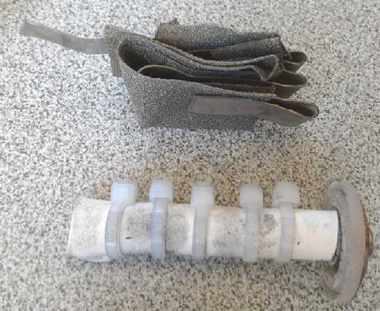 Maybe I needed
to get back to real basics? I had the
cupro-nickel strip - that's the simplest possible negode. If desired I
could wrap that in some 'nickel foam' to gain capacity. For a 'dead
simple' plus side, maybe some nickel oxide powder trapped in paper
wrapped around a graphite post, and test that with a space between the
electrodes in the K2SO4? In pure K2SO4. At this point
all we care about are the voltage and that there is no self discharge.
Maybe I needed
to get back to real basics? I had the
cupro-nickel strip - that's the simplest possible negode. If desired I
could wrap that in some 'nickel foam' to gain capacity. For a 'dead
simple' plus side, maybe some nickel oxide powder trapped in paper
wrapped around a graphite post, and test that with a space between the
electrodes in the K2SO4? In pure K2SO4. At this point
all we care about are the voltage and that there is no self discharge.
I made the posode with the rod from an old C cell battery.
I sprinkled some nickel hydroxide on watercolor paper and then because
it's so poorly conductive I sprinkled a little carbon black on that and
sort of mixed it around. Then I wrapped the paper around the post. I
used 5 small cable ties to hold it on - at least where the ties were,
the stuff would be at least a little pressed against the post.
I thought more surface area than just a piece of etched
sheet metal would be highly desirable for the negode. Yet I wasn't
going to bother with trying to press and hold nickel powder into good
connection with the sheet. Instead I Cut a piece of nickel foam about
1.5" x 7".
 Etched nickel foam close-up. One end (right, I
think) is over-etched. The other is about right. A band in the center
is unetched.
Etched nickel foam close-up. One end (right, I
think) is over-etched. The other is about right. A band in the center
is unetched.
(The appearance here doesn't really seem to match my expectations.)
In order to further increase the surface area of the
nickel foam, I folded one end sideways and stuck it into some ferric
chloride at room temperature. After 28 seconds wafting it back and
forth, suddenly the dipped end became floppy and the fold unfolded.
Evidently that was too much! The fold ripped at one end, and later the
whole piece broke off there.
I tried again with the other end for 10 seconds, and it
took 3 or 4 more to pull it out and spray some water on it to wash the
ferric chloride out of the pores. That was probably about right. It
looked a little darker and duller than before. Under a strong
magnifying glass (10x & 40x) the initially smooth surface now
looked pitted all over, very tiny pits. That would certainly increase
the surface area.
An ideal electrode now (in my view) would have the etched
cupro-nickel sheet as a backing and running up to the terminal post.
This would be covered by the etched nickel foam. Sifted into the foam,
and probably covering it to make it all deeper, would be the micro-fine
nickel powder. All this would be pressed together, probably without a
lot of pressure (which might disintegrate the foam), and stuffed into a
space in a battery that would prevent it from expanding, at least by
very much. If the nickel powder wasn't fine enough, it too could be
etched for a few seconds and then rinsed. (Probably an experiment worth
trying with any nickel or monel powder - but only once a working
battery has been created.)
I simply stuffed the pieces of foam into the folds in the
cupro-nickel sheet. I might hope it would now have at least some
real capacity.
That left the potassium sulfate. There is no chemical or
lab supply store in town. Aside from the probably contaminated jar of
that salt derived from used battery acid, I had some pure sulfuric
acid, potassium hydroxide, magnesium sulfate (epsom salt), and some
copper sulfate crystals. The magnesium or copper sulfate
might be interesting and I'll try adding some of them, or even using
one instead - later. For now I decided to go with pure K2SO4.
The 50cc of acid bubbled and hissed as I sprinkled in a
little bit of hydroxide at a time. I put the beaker in a plastic tray
of shallow water to keep it cooler. My latex single-use gloves seemed
to weaken with hydroxide on them and the thumb ripped off of one when I
took them off. (Yes I wore a full face shield - I've met the blind
chemist. and my London Fog "lab coat".) As I added more and more
hydroxide flakes, the pH stayed stuck on "1", but the mixture became
cloudy and there was white powder drifting around on the bottom. All I
could think at first was that the hydroxide, highly soluble as it is,
hadn't dissolved yet. Maybe it would and then I'd find the pH was too
alkaline. Then it occurred to me it would be the desired potassium
sulfate, which is much less soluble than either the acid or the base.
Ah, that made more sense! I stopped and left it for a while. When I
added flakes of hydroxide the bubbling was now much less intense. After
one application the pH went from 1 to 13 or 14. A tiny dollop of acid
and it was back to 1 or 2. A few flakes of KOH and it was back to 12 or
13. Yeesh! The water in the beaker was nearly full of white powder
drifting around. I figured I was done and poured it into a plastic
jar... and labeled it.
I put the
electrodes and some of the liquid (diluted until
it dissolved) into a small ointment jar. It read about 1/4 volt, but as
soon as the slightest charge was applied it jumped to 3 volts -- it
really was hardly working. The negode could hardly fail, but I guess
the powder particles in the plus side, not compressed with the 20 ton
press, weren't really making contact with each other. It seemed to need
something better, and various unsatisfactory means for making
well-compacted powder electrodes with a carbon or graphite electrode
terminal started coming to mind. Luckily I left it on charge anyway and
went out to work on the Sprint car drive.
I came back and found the charge voltage had dropped to
about 1.5 volts, all by itself. The electrode had started working! This
may be explained by the fact that beta Ni(OH)2 is a very poor
conductor, but the conductivity rises when about 1/4 of it is converted
to NiOOH - apparently by much more than I had realized. I left it a
while longer and shot some video of the car being coaxed into motion. I
came back and disconnected the charge. It held charge much better than
the previous cell, taking around half an hour to drop to 1.3 volts and
another hour to 1.2. And it held above a volt with a 100 ohm load for
maybe 15 seconds, and the voltage gradually rose back up afterward.
(Later it ran for 10 minutes above a volt with a 1000 ohm load, and
after 25 minutes was down to .75 volts. Even then it was still losing
voltage only gradually. With better electrodes those voltages should be
higher.)
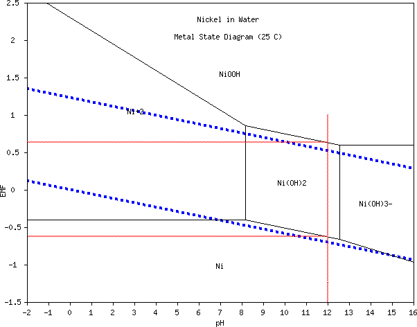 Let's see... the open circuit
voltage ought to be... theoretically... (and apparently almost
regardless of pH from 8.5 to 13) about .65v - -.6v = 1.25 volts. With
some current being drawn, we are probably going to call the nominal
rated voltage "1.1 volts". So it'll take 11 cells in series to make a
12v battery. This is a bit disappointing. Oh well! (...Or does nickel
mangante, which I'll use, have a bit higher voltage than nickel
hydroxide?)
Let's see... the open circuit
voltage ought to be... theoretically... (and apparently almost
regardless of pH from 8.5 to 13) about .65v - -.6v = 1.25 volts. With
some current being drawn, we are probably going to call the nominal
rated voltage "1.1 volts". So it'll take 11 cells in series to make a
12v battery. This is a bit disappointing. Oh well! (...Or does nickel
mangante, which I'll use, have a bit higher voltage than nickel
hydroxide?)
I don't know about this "Ni(OH)3-" ion shown at pH 13 and above. It
doesn't seem to be any standard part of pH 14 alkaline battery
chemistry in the literature, nor is it shown in the charts (from CRC
Handbook?) on the web. One source does say a "higher oxide of nickel"
(KNi(OH)2) is occasionally found in the posode. Thus it doesn't look
like anything that should plague us at pH 13 or lower.
Two reasons the cell might continue to gradually self discharge even if
the chemistry is sound are:
1. The posode has poor conductivity. Powder that never got charged
might gradually drag down the charged parts. Charging far longer might
bring them up and then the self discharge should be reduced. (It wasn't)
2. Oxygen from the air may be entering the liquid and discharging the
negode. The cure for this will be a closed top to pretty much eliminate
air circulation, instead of an open jar.
3. Self discharge got worse after a couple of days. The carbon rod was
from a standard "C" cell that used ammonium chloride and maybe zinc
chloride electrolyte, and it was simply brushed off to clean it.
Perhaps some NH4Cl and or ZnCl2 was impregnated within it and came out
to contaminate the solution. In fact, the solution now had a tint to it
where it was clear originally. There's no manganese... unless it too is
a contamination from the rod... so whatever it is probably came out of
the rod. (Now I'm soaking all my carbon dry cell rods, and that
electrode, in water for a few days.)
A zinc or plain graphite electrode inserted momentarily to measure
voltages against might be able to ascertain which electrode is losing
charge, or if it's both. But such cheap test electrodes tend to change
voltage as you watch,
making it tricky.
I meant to leave the cell
charging overnight, but I connected the alligator clip to "load"
instead of "charge", and it was quite dead in the morning. I left it on
charge for nearly 3 hours, then took it off. After an hour or so it was
still at 1.347v and dropping only a millivolt per minute. After almost
3 hours, it was still 1.304v, and after 6 hours 1.18v. That rate of
self
discharge is probably
similar to my most successful 2.6v NiMn cells. (I wonder how those
would
work with K2SO4 electrolyte?) I'd say it's working great, which is
totally different than the results I was getting with KCl electrolyte.
The NiMn cells seemed to work with KCl, and the NiNi works in K2SO4, so
apparently it's some spontaneous reaction specifically between the
nickel negode and KCl, or the Cl- ion is a catalyst for self discharge.
So next it's time to work on many and various refinements. A list might
include:
* something to glue electrodes together, especially the plus
* Oxygen overvoltage suppressor (Sm2O3?)
* Improved nickel manganate posode formulation (more conductive,
more capacity than traditional nickel hydroxide)
* Some good electrode construction including the protruding
graphite or carbon terminal
* Hydrogen overvoltage suppression is probably unnecessary owing
to the low reaction voltage of metallic nickel to nickel hydroxide.
It's .1v below the hydrogen reaction voltage.
* Some good electrode construction including the protruding
cupro-nickel terminal.
* Some good cell construction.
On the 29th I did a bit of reading on glycerides. They're
used in making soap, by adding sodium hydroxide. If an electrode were
mixed with a glyceride, the hydroxyl ions in the electrolyte should
soon turn it into 'soap' - or more hopefully soap solids - to 'glue'
the electrode together. This
would replace the Sunlight dishsoap I've been using all along. Again
pure chemicals instead of household stuff should help prevent self
discharge. And really I'm hoping for something with some electron
conductivity, which would ensure that even a poorly compacted electrode
would have all its powder connected to the terminal. Stearol - beef fat
or tallow - is a triglyceride. But maybe
just some USP purity glycerin (glycerine, glycerol) from the drug store
would work. I'll try that first.
The nickel-iron flooded pocket cell electrode comes to
mind as a structure for the negode (only). Instead of an etched
cupro-nickel backing sheet, perforate a double size sheet (perhaps with
the pin frog / flower frog with soft wood underneath, on a press) and
use it as the the outside shell of the pocket electrode. The inside
would have a sheet or two of etched nickel wool for super conductivity
and would be stuffed with micro nickel (or monel) powder. (which also
might be briefly etched - experiment later.)
Perhaps a 'die' could be made for the press that would
crimp the edges together as it compacted the shell?
I thought this
would make a fabulous electrode! Right after
I wrote the idea (night of 29th) I tried it, but making it turned out
to be a problem. Using a small pin frog (40mm? OD circle) the soft
piece of wood (lombardy poplar) simply crushed under a ton of pressure,
with hardly any pinpoint indents in the metal, which became bowl
shaped. Two tons just made it worse. So I picked a harder wood,
dogwood. Under 3 tons of pressure, there were indents in the sheet at
each pin, but no actual perforations. When I tried again, under not
much more pressure, still about 3 tons, the pins all suddenly bent
over. Later I noticed they were also dulled. Scratch one pin frog,
still no perforations! Unfortunately, the
sheet was just too hard for that technique. I can either try some other
electrode build entirely, or anneal the sheet and then try it (I think
it's tempered), or anneal it and run it through the rolling mill to
make it thinner first. Unless I can find something tougher than a pin
frog. (Annealing only made it a little softer. And I'm not risking my
rolling mill on such hard sheet.)
For a positive electrode, Edison's round perforated tubes
stuffed full of nickel hydroxide powder and nickel flakes under many
tons of pressure come to mind, but at pH below 14 any metal tube would
oxidize and disintegrate. If I drilled holes in and stuffed a plastic
tube, the carbon rod would crack to fragments in the pressing.
Okay, perforated plastic tube stuffed with Ni(OH)2 and
conductive carbon black, then a hole drilled down the middle of the
powder. Sand a taper onto the carbon rod, then stuff it into the hole
to compact against the powder. Yikes! But it should work.
How about a flexible plastic syphon hose? They come in
various sizes, stiffnesses and wall thicknesses. One could surely
perforate it easily with a pin frog in a press.
But two thicknesses of
metal to form a pocket is more weight and more costly, while adding
only a minimum of capacity to the cell. And plastic adds nothing but
bulk. Having failed to perforate the metal anyway, maybe I should go
back to the typical manganese-zinc
dry cell layout? I found making one tedious, but at least I am set up
for making one-off cells, as developed earlier. (See TE News #86, 87,
88 & 89.) Perhaps I can improve on the methods.
If there was some way to make a cupro-nickel can, it would
be like a zinc dry cell can only it shouldn't corrode away, and the
plastic PVC pipe can housing would be unnecessary. That would require
(a) some kind of sophisticated metal spinning and forming setup, for
quite a hard metal, or else (b) something to weld the sheets into cans
with nickel or cupro-nickel welds, and with no leaks, or (c) powerful
crimping devices to shape two pieces and crimp together very solidly
first the seam of the tube and then the bottom piece to the tube piece.
And then a plastic top could be crimped on. But these sound like hard
things to set up for, for some sort of mass production.
On the other hand, perhaps cupro-nickel tubing is
available. Perhaps one could crimp on a plastic bottom as well as a
plastic top, and the tube would be the outside casing?
http://www.TurquoiseEnergy.com
Victoria BC Canada