Turquoise
Energy Ltd. News #99
covering April 2016 (posted May 6th 2016)
Victoria BC
by Craig Carmichael
www.TurquoiseEnergy.com
= www.ElectricCaik.com
= www.ElectricHubcap.com
= www.ElectricWeel.com
Features:
* A New Battery Chemistry: Air-Nickel in Potassium Sulfate -
High
Energy & probably Easiest DIY Battery Ever! (see Electricity
Storage)
* Chevy Sprint/Variable Torque Converter Transmission: Basic
Driveability at Last! (see Electric Transport)
* Another New, Super-High Performance Motor Type: Permanent Magnet
Assisted Motor (see Electric Transport)
Month In Brief
(Project Summaries)
- Chevy Sprint with Variable Planetary Gear Torque Converter: it rolls!
- Nickel-Air Battery - Electropermanent Magnet Motors - Permanent
Magnet Assisted Motors
In Passing
(Miscellaneous topics, editorial comments & opinionated rants)
- Geo-engineering, Climate Disasters, Social Evolution
- In Depth
Project Reports -
Electric Transport - Electric Hubcap Motor Systems
* Electric Hubcap motor, Chevy Sprint & Variable Transmission
* "Permanent Magnet Assisted" Unipolar Motor?
* Unipolar Motor "Breakthrough"? Oops.
Other "Green"
Electric Equipment Projects (no reports)
Electricity Generation (no reports)
Electricity Storage - Turquoise Battery
Project (NiMn, NiNi), etc.
* Self Discharge: Probably Caused by Graphite in the Positrode.
(Graphite surface needs to be
oxidized)
* News Report Confirms that Jelled Electrodes make for Virtually
Indefinite Cycle Life
* Conductive Carbon/Graphite Rods
* Notes on the Nickel Negative Electrode
* Self Discharge: Attempting to eliminate it. ... It must come from the
positive electrode.
* Nickel-Air (Air-Nickel) Battery
- Graphene or Graphene Oxide Layer on Plastic Film
- Rethinking It!
- Nickel Advantage?
- Cell Design & Humidity: moisture level maintenance
- 2 Test Cells
No Project Reports on: Lambda ray
converter, CNC
gardening/farming machine, Electric Weel, unipolar motor controller,
reluctance motors (will need to modify the controllers and motors for
electropermanent magnets - or just the motors for "permanent magnet
assisted" motors!).
April in Brief
April seemed to march by pretty quickly, but not without an
exceptional
share of good ideas and good project progress. First I was tipped off
(by Leonardo Janus again) to "Permanent Magnet Assisted" Motors. This
is a
variation on the electropermanent magnet motor, but it seems much
easier to
apply to my motors because it can use the same ARM reluctance motor
with some neo magnets added, and the same unipolar motor controller
I've been developing.
 Then I had
considerable success with the variable transmission, as
installed in the Chevy Sprint car. With flywheel inertia to initially
start it into motion - and a little practice by the driver - the car
can be driven on the lawn, and, given enough room to roll (which I
don't have where it is) would surely pick up speed. At this point I'm
not confident
about starting up hills and sufficient acceleration for the street, but
it goes substantially better in forward than in reverse, so it may be
that adjustments can markedly improve performance in both directions. A
heavier flywheel first tried on May 1st seems to help the car start up
better on upward slopes, and readily got it into motion where it needed
20 foot-pounds at the shaft to do so (80 ft-lbs at the wheels), instead
of the 10(/40) that had been the max for a while. On May 3rd it rose
over a board placed in front of a wheel, that required 30 foot-pounds
(/120) - but only for a short distance, and on the third try. If
it's not enough for the street, it's in the ballpark.
Then I had
considerable success with the variable transmission, as
installed in the Chevy Sprint car. With flywheel inertia to initially
start it into motion - and a little practice by the driver - the car
can be driven on the lawn, and, given enough room to roll (which I
don't have where it is) would surely pick up speed. At this point I'm
not confident
about starting up hills and sufficient acceleration for the street, but
it goes substantially better in forward than in reverse, so it may be
that adjustments can markedly improve performance in both directions. A
heavier flywheel first tried on May 1st seems to help the car start up
better on upward slopes, and readily got it into motion where it needed
20 foot-pounds at the shaft to do so (80 ft-lbs at the wheels), instead
of the 10(/40) that had been the max for a while. On May 3rd it rose
over a board placed in front of a wheel, that required 30 foot-pounds
(/120) - but only for a short distance, and on the third try. If
it's not enough for the street, it's in the ballpark.
Finally, with yet another
battery cell with high self-discharge problems, I changed tack... and
stumbled onto what may be a better
EV battery in almost every respect - better than I was trying
for. In keeping with the usual tradition of putting the positive
electrode first, it should probably be called "Air-Nickel", in K2SO4
electrolyte. But air-zinc and others have come to be known as
"zinc-air" instead. Which
convention to follow? "Nickel-Air", then?
With the heavier, bulkier positive electrode substance
eliminated,
nickel-air cells could be half the weight of Ni-MH, and lighter than a
lot of lithium cells. In order to allow free air access to each
exposed, flat, air electrode surface, a stack of them would be bulky:
half the weight but twice the bulk. Another problem with air cells is
maintaining a
workable moisture level in the cell, but I accidently found there may
be chemical ways of solving this. Or perhaps a DES electrolyte could be
used, and would evaporate so slowly the issue would be trivial? With a
gelled nickel electrode, the cell should last virtually forever.
After one hastily slapped together cell that shorted from
invisibly tiny carbon/graphite fibers, I put together a more proper
cell, 3" x 4" and only about 1/8" thick. It went together easily. In
fact, it could be by far the easiest DIY battery to make, ever!
 Flat Nickel-Air Cell.
The layers from the top are:
* Permeable Transparent Plastic Adhesive Label (in fact, almost
invisible), stuck onto...
* Conductive Carbon (Graphite) Fiber Cloth Electrode (with "graphite
foil" positive terminal strip)
* Separator Paper (Arches white 90# watercolor paper)
* Nickel Foam impregnated with Nickel Micro Flake Powder gelled
in Glycerin
* Cupro-Nickel 70-30% sheet metal negative electrode, support sheet
& terminal.
* Later the paper was wetted with Potassium Sulfate electrolyte
* and the edges were sealed with beeswax.
Then I discovered that the
high self discharge that has plagued all my battery making efforts is
probably due to the graphite in the positive electrode and hence is
similar in every cell I've made regardless of chemistry. The solution
is probably to oxidize the surface of the graphite: with weeks of
charging current, or by pre-oxidizing it with strong hydrogen peroxide
or perhaps bleach.
In other battery news, I've retired the Toyota Tercel,
still with the 30 NiMH D cell battery installed in 2011. It is
doubtless somewhat weaker than when it was new, but it was still
starting the car - as long as it wasn't left sitting for days with a
door ajar. In the Mazda RX7, pretty much sitting since April 16th when
the insurance expired, one of the five sets of 12v, 100AH NiMH cells
ran down to 10.9v while the others were still 12+v. I figured there was
some bad cell dragging it down. But when recharged for a day or so, all
of them stayed up fine. They seemed to appreciate the rest rather than
continual float charging.
I also spent time every day in the garden, which was dug
and
prepped in March, planting vegetables
including potatoes and corn as well as greens. It has been an amazingly
warm
spring and on some days I feel like I must have moved to California. I
may get two crops of many things. It's not so long ago I remember
starting a garden near the end of June because the spring had been so
cold, wet and miserable. If food deliveries do
indeed run into problems this year as some are predicting, it may
alleviate personal shortages. But of course, the more you plant, the
more there is to water and weed. And it's looking to be really dry.
Since the winter deluges, my hilltop tank has already run out of water
from garden watering, when it should still be refilling now and then.
Toward the end of the month and into May I did some work
for AGO
Environmental Electronics, soldering and assembling water resistant
slip ring assemblies for ship winches, and this also ate into my time
(hence the late newsletter).
Notwithstanding that I need the money, I hardly got
anything done on my 2015 annual "Scientific Research and Experimental
Development" report to Canada Revenue. It seems like such a
distraction. Ideally I should have done it in March. I certainly
wouldn't have got as far on the fine April developments if I had spent
my time on that.
Electropermanent Magnet Motor Field
Last month I mentioned a web search where I could hardly
find the term "electropermanent magnet motor". But it was an
exaggeration to say that that seemed to indicate it was a totally new
field. It's the term that's new. There was the 1962 machine. And
someone has done one in 2006 or earlier, albeit operating a little
differently than the prototypical "electropermanent magnet" of the
video linked in TE News #97, that seems to put out more elecricity than
it uses: http://www.peswiki.com/index.php/Directory:Hilden-Brand_Electromagnet_Motor
. And the (2012?) Zero Electric Motorcycle mentioned the motor was
"permanent magnet assisted". And
someone recently asked me if I could make "Electric Hubcap" motors as
generators for a self turning motor, one that is probably
electropermanent... or permanent magnet assisted... in some fashion or
other.
After a while I started realizing that 'electropermanent'
and 'permanent magnet assisted', while both gaining advantage from
supermagnet flux fields as a common feature, were really significantly
different types of motors. And my own idea for using only AlNiCo-5
magnet cores and no neo supermagnets is really markedly different again
from anything I've seen explained or have seen rumors of.
Permanent Magnet Assisted Motor
After thinking overnight about the motor in the above
video, which link was sent to me on the 3rd, I started to realize it
has some very specific advantages over the AlNiCo-5 designs. The
revolutionary potential may (or may not) be less, but it also has
practical developmental advantages. In the first place, since it uses
regular soft magnetic coil cores, it has the same driving requirements
as my other motors. A BLDC4-3 motor such as Electric Caik or Hubcap, or
a reluctance motor, could be made using the unipolar controller I've
already been designing, instead of a completely new controller with
some tough to meet driving specs.
The motor would have a cylindrical supermagnet, 1.25" O.D.
and 1" long, filling in the center of the iron powder toroid cores.
(Being unipolar, all would be oriented the same direction, which would
also be the direction of the activated coils.) Then they would no doubt
need some sort of magnetic 'shorting bars' or 'keepers' that would
short the field within themselves if the coil wasn't activated. (Or
maybe they wouldn't since the supermagnet and the coil core are in
contact along their length?) When the coil was activated, the
supermanget strength and the coil strength would be added together
externally, increasing the flux and hence motor torque over what the
coil power would do by itself.
If I could find the above size of magnet, it might turn
into
a pretty simple project. One problem likely requiring redesign of the
body part molds will be the "buttons" the coils are mounted on. Unless
supermagnets shorter than 1" can sit inside the toroid cores. That
might be worth an experiment in itself.
Later I located and ordered some 25mm O.D. by 20mm disk
magnets. These will be centered within the 1.25" I.D. space of the
regular toroid coil cores, and the extra 5.4mm to get to the 1" height
will be the thickness of the shorting bar, a 1.25" O.D. piece of soft
magnetic iron or steel. I noted that the Toronto company I got them
from also sold laboratory glassware and I got a bunch of that for the
battery lab.
About the end of the month, some friends wanted to see the
Miles
electric truck run. The driver's inside door handle broke off, but a
couple of good trips on the street appear to have
confirmed that the repair was good and it runs reliably. I still don't
like backing it up! Someone with a camper has suggested a back-up
camera. Perhaps that would would be good solution. That and a new door
handle, fix the window winder, fix the seat back adjuster, fix the
state of charge indicator, and add a voltmeter (or several, to show
individual batteries), and it should be quite nice.
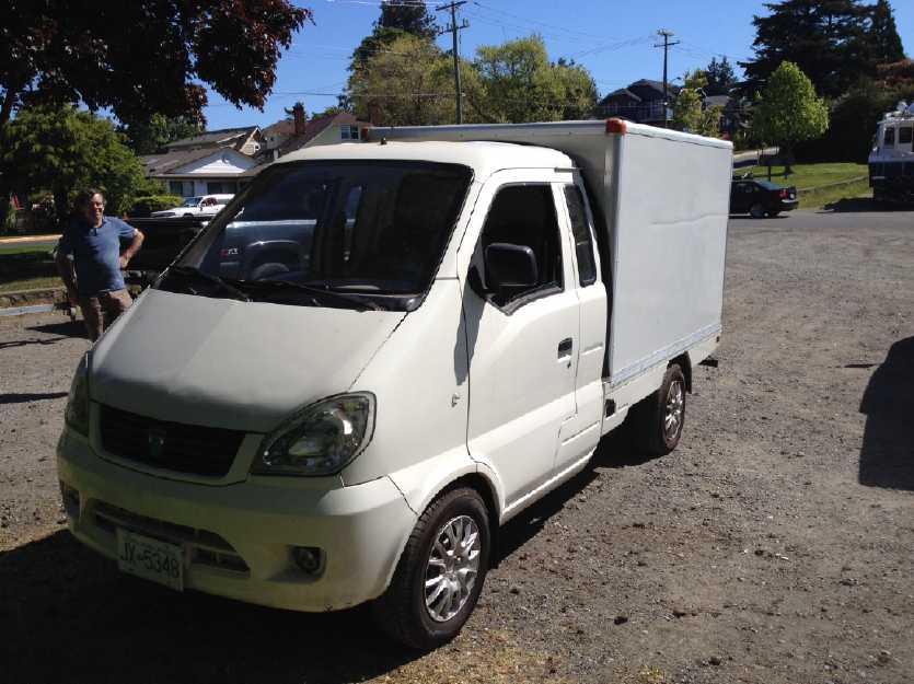 The Miles Electric Delivery Truck out on a Road
Trip
The Miles Electric Delivery Truck out on a Road
Trip
In Passing
(Miscellaneous topics, editorial comments & opinionated rants)
Geoengineering, Climate Disasters, and Social Evolution
At a media forum, Truth and Justice in St.
Petersburg, attended by many independent Russian and other journalists
and also some politicians, someone
asked
a
question
of
a
former German defense minister, Willy Wimmer, and he
had a few things to say. Russian president Vladimir Putin astonished
everyone by jumping
in with a microphone and translating Wimmer's fairly extensive German
reply into Russian for the
assembly.
Later Wimmer was interviewed by a news channel (in
English) and was asked if Putin's seemingly impulsive act might have
been rehearsed. Wimmer said the question wasn't known in advance much
less his answer, so that would have been impossible. (He also said
that after all his time in politics, he had just learned at this forum
about the workings of Swiss democracy.) The interviewer then asked
something about a "war on information". Wimmer said he objected to that
term. It was an American term, and the Americans always had a war on
something. Next year they would have a "war on sunshine." I laughed at
that.
But then I realized he's actually behind the times. They
already have an undeclared "war on sunshine" with all the chem
spraying. I think
there are those involved who take some sort of perverse satisfaction
when they hear
of solar panel installations being far less effective than expected
because
of the continual haze being spread over the sky. And maybe when they
hear of mass dieoffs of fish, birds and even pollinating insects, too.
Perhaps they started out sincerely believing, or at least
vainly hoping, that what they were embarking on was going to halt
global warming and help make things better. Such motives, up to that
point, are at least fairly benign. But they can hardly have failed to
notice
the devastation and the rapid acceleration of arctic warming, and to
realize the atmospheric blanketing effects of the sprays are the
obvious cause. To continue beyond that point is to live a
lie - dam the destruction, it's the chosen path and I'll hold to it
even knowing it's working evil. I get paid for it and jobs are scarce.
We can't
shut the whole vast operation down new!
On May 3rd, "Tar Sands capital" Fort McMurray, Alberta was
in the news for the whole town being on fire with all 60,000 people
being evacuated as fast as the meager highways permitted. The
government of BC said that they were presently busy fighting several
major forest fires in northern BC already and so were too busy to help.
(Did those even make the news?) This is only the start of May. The snow
should hardly have finished melting, but around Ft. McMurray it was
32°C - July weather! Last summer (as I wrote then), it seemed half
the world's boreal forests were on fire. This summer is already set to
surpass that - devastation on a planetary scale is underway.
 "Chem Spraying" I saw while walking, over
Victoria BC Canada, April
2016.
"Chem Spraying" I saw while walking, over
Victoria BC Canada, April
2016.
Farthest (west) freshly released sprays are thin lines. As they drift
east toward Victoria,
instead of dissipating and
disappearing like regular contrails, they simply spread out wider and
wider,
until over town, the whole sky is
covered with silvery or (as others have said) "milky white" haze.
Some lower clouds look real - it gets hard to tell for certain.
The planes apparently come from Whidby Island Air Force Base in
Washington state,
and can be heard taking off from Eastern parts of town, often several
per hour, a roaring, rumbling sound.
It would seem they spray up and down the entire west coast of Vancouver
Island.
Normally very few jets fly over Victoria as it's not between any two
important population centers.
All those involved - not to mention
everyone everywhere - should remember that when their life on this
world is over, they will have to face what they've done on the worlds
on high. Ascending mortals are adjudged in mercy and with full
consideration for the confused, mall-administered planet they hail
from, but when each of us comes face to face with the universe
consequences and outworkings of his deeds, will he raise his head
proudly, saying "I contributed that"?
The world is improved as individuals improve it, and
degraded as individuals degrade it. We are its stewards and we have the
gift of freewill, but it is not in the divine plans nor to any universe
advantage that a beautiful
planet with a vast array of diverse climates and landscapes, patiently
created and evolved over billions of years, be rendered polluted
and lifeless, robbed of a glorious future by those in charge of one
misguided and senseless semi-civilized generation of its inhabitants.
But it is getting to be quite a disturbed and degraded environment that
is being left for coming generations to clean up.
And of course, all these things are symptoms of a grand
malaise that started with the Lucifer Rebellion of long ago. The root
causes are an evolving society with a lack of caring or lack of
examination and action on facts, with insufficient attention to what's
going on, enabling the creation and perpetuation of obsolete and
unsustainable societal systems, institutions and occupations that
aren't under citizen control. Ones' own self and ones' family exist in
a broader social context on a planet that can easily accommodate a
certain number of people (whether that's 1.5 billion or 3, or more -
partly depending how we live), but is deteriorating rapidly and heading
towards collapse just as was projected even by "Club of Rome" studies
in the 1960s if the population was permitted to continue to grow
unchecked.
Hoping to assist with guidance in the social evolution
that is already starting to take place, just for starters, are my own
new www.HandsOnDemocracy.org
writings, and a recent book by Daniel Raphael, PhD: Social
Sustainability Handbook For Community Builders.
Newsletters Index/Highlights: http://www.TurquoiseEnergy.com/news/index.html
Construction Manuals and information:
- Electric Hubcap Family Motors - Turquoise Motor Controllers
- Preliminary Ni-Mn, Ni-Ni Battery Making book
Products Catalog
(Will accept BITCOIN digital currency)
...all at: http://www.TurquoiseEnergy.com/
(orders: e-mail craig@saers.com)
Electric
Hubcap
Motor
Systems
-
Electric
Transport
Electric
Hubcap motor, Chevy Sprint & Variable Transmission
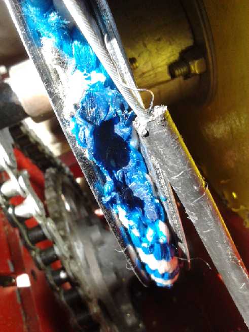
I've been having a hard
time pulling the tensioning rope hard enough to bring the pulley to a
stop, or even to near a stop, under full torque. On the 2nd I went to
Castle (ex Rona) building supply to get a thicker polypropylene rope to
try out. They didn't even have the same 3/4" thickness, just thinner.
Well, maybe a thinner rope would fit the pulley more solidly? I brought
home pieces of 1/2" and 5/8". The 1/2" one slipped worse than the
original 3/4" one. Maybe I'll have to rough up the smooth pulley
surface with a grinder or sandpaper?
On the 3rd I connected up the driver controls -
forward-off-reverse switch and electron pedal - to the Kelly BLDC motor
controller. Loathe to cut the plug off the connector for my own motor
controller, I removed the whole cable and made up a new one. But the
light on the controller flashed '... ...'. That error code turned
out to be "hall speed control open or shorted". When I made it I used a
10K ohm potentiometer ("pot" for short). Nothing in the diagram said
what the resistance should be, or said that it was critical. Since it
simply panned from 0 volts to 5 volts, which it could do with virtually
any reasonable resistance value, it didn't seem like something that
should be critical. I opened up the Kelly test control box. Its pot was
2.5 K ohms. It's okay to ask for a specific resistance value, but the
least they could have done was to tell the customers that there was
one, and what that value was! I could have ordered a 2.5 K pot at any
time in the last 2 years, but now that I need it I don't have it. I
could try bridging the pot (ie, across the 5 volts) with a smaller
resistor. That might or might not work.
But I did (at considerable expense) get Kelly's own
("Qiang" brand) 'electron pedal', a nice, rugged unit which appears to
have a hall sensor in it rather than a pot. I decided the best thing to
do was to replace the Sprint pedal that had my pot attachment, with the
Kelly one. That got into doing new mechanical mounting along with the
wiring.
The mountings were in totally different places. I decided
to try the resistor on the old pedal. Let's see... as best I recall...
Rparallel = R1*R2
-------
(R1+R2)
So
2500 = 10000*R2
-----------
(10000+R2)
So R2 = ...I've never been any good at this... Let's just try R2 = 3300
ohms in the formula.
Then Rparallel = 2481 ohms. Close enough. (Apparently R2 should be
3333.3333 ohms)
I put the pedal back in and wired in the resistor. It
didn't help. Then I put a brick on the pedal to hold it part way down,
then turned on the power again. I got a new error, '.. ....' which
turned out to be "throttle above dead zone at startup". Hmm... If I got
the brick just right, the green light came on. I measured the pot in
the Kelly control box. It only went down to 70 ohms when off, not right
to zero. 70 with a 2.5K pot is 280 with a 10K pot. I put a 330 ohm
resistor in series with the pot ground connection. Now the pot in the
pedal couldn't go below 330 ohms to ground. This time, the green light
came on and the motor ran! Now I removed the 3300 ohm resistor I had
put across the pot. It still worked fine. With the fwd-off-reverse
switch down the motor changed direction. All good!
I had also sometimes got the 'open or shorted' error with
the Kelly control box at full throttle. Sure enough, the throttle
control in the box measured 0 ohms to the "+5" when at full throttle.
Doubtless that end can be cured with a small resistor, too. Since
nothing is said about it, apparently they are counting on crappy pots
that don't quite go all the way to each end!
The manual does say: "Standard
Throttle Input: 0-5 Volts(3-wire resistive pot), 1-4 Volts(hall active
throttle)." Apparently it's
operating on the assumption that it's 1 to 4 volts, and it's flagging
an error if it's more or less. No doubt that can be reconfigured if you
have a way to program it. I'll just put resistors in series with the
throttle pot, top and bottom, to reduce the range!
That took up all the time I had, but at least I figured it
out and got the motor to run from driver's seat. If there'd been a note
in the user manual trouble shooting section explaining the conditions
under which the '... ...' lights would blink, it could have been a
whole lot easier. The next day (5th) I soldered in the two resistors. I
made them 470 ohms in case 330 was just on the edge of working. The
green light came on and it worked fine.
The next morning I had an idea, to try letting the
slipping pulley slip until the rope and pulley started to heat up. I
pulled the rope to "moderately tight" with the shift lever. As usual
everything just turned and the rope slipped. But after just a few
seconds - just after I normally would have given up and stopped - the
rope started jerking on the pulley and the car shuddered like it was
about to start moving. It didn't, but it seemed to be almost there, and
with much less tension on the rope than I had been using. I also had
the thought that the tension rope seemed to need a spring on it to
maintain a more even tension. Also that I should adjust the motor
mounting for a better fit on the thrust bearing, which holds the pulley
in place. It wasn't quite straight and had too much room to wobble.
 After a few
tries the motor had got hot even faster than
the rope and started to steam or smoke, so I quit. It was definitely
time to drill out those air circulation holes! I hoped that would be
enough, but given the speed of heating my confidence was low. And if I
had to derate the motor to half what it was, to 3.6 KW to prevent
overheating, it certainly wasn't going to put cars on the road.
After a few
tries the motor had got hot even faster than
the rope and started to steam or smoke, so I quit. It was definitely
time to drill out those air circulation holes! I hoped that would be
enough, but given the speed of heating my confidence was low. And if I
had to derate the motor to half what it was, to 3.6 KW to prevent
overheating, it certainly wasn't going to put cars on the road.
When I took the motor off for adjustments, I drilled the
air exhaust holes out from the 9/64" holes of the CNC drill-router
template to 1/2". That should move a whole lot more air.
But I soon realized that
the shuddering was due to a rope
clamp (plumbing hose clamp) hitting the pulley and grabbing. With the
old fatter rope, the clamps had sucked in inside the diameter of the
rope when I tightened them. With this one they stuck out. In fact, the
motor jammed and wouldn't always run in reverse. And having adjusted
the motor, after some more tries the thrust bearing was loose again.
The shuddering had put so much force on the shaft that it had pushed
the set screw in the chain sprocket sideways and the shaft was again
loose side to side. (I had only done up one of the two for the moment.)
On the 9th I put on the 5/8" rope I had also purchased.
This time I put in a spring for the tension. It fared better for going
forward, but the pipe clamps touched the pulley and kept the rope from
tightening for going backward, so it just slipped freely. In forward, I
could rev up the motor, pull back the stick, and as long as it didn't
need more than about 10 foot-pounds to the chain (40 ft-lbs at the
wheels), the car started moving. A couple of times, if I just let the
pulley slip without very much tension, the car started moving after a
few seconds. Either way it didn't accelerate well, and it didn't seem
to take much to stop it. More than 10 foot-pounds was a no go. Why was
it having such a hard time delivering such a small amount of torque?
And the motor still got hot fast. I started wondering if
even a special fan blowing air straight onto the coils would be
sufficient. I started to think that before I went much farther, I
wanted to be able to see the voltage, current and temperature on the
dash. Preferably with a temperature alarm, a beeper.
150 amps times 36 volts is 4800 watts (a little over 6
HP), but if the
overloaded batteries are dropping to, say, below 7 volts (extreme
case), 150 amps
times 20 volts is only 3000 watts. It would be good to see if that's
happening, or how badly that's happening. (It really should have 300+
amp-hours of batteries to provide sufficient current without straining
them. At the
moment for testing it's
just around 100 amp-hours - three size 'frame 27' deep cycle lead
acids.) Which leads to the thought that in 2012, when I only had maybe
about 1 KW, I must have had around 25 foot-pounds or 100 at the wheels
- once the car was moving, and if only at about the best point for 4 or
5 feet of distance it went. I wasn't getting that now.
But the start-ups with the rather loose tension started me
wondering if I had made a mistake in 2012. Could it be the torque
conversion actually works from 0 RPM? But why does it take several
seconds before the car starts moving? I started to think that maybe it
might all be a matter of fine adjustments to the tensioning system, and
I decided to concentrate on that.
On the 14th I bought a stronger spring, and an eye hook
screw. I shortened the rope a couple of inches to accommodate it (I
"cut" it with a propane torch) and screwed the eye screw into the end.
Then I tightened a hose clamp around it. that seemed to make a good
assembly for that end, the 'move forward' end. With the tension on
light, the car started moving almost immediately, but it still had to
need under 10 foot-pounds or so, or it wouldn't move.
I went out to the car on the 19th and revised the rear end
of the pulley rope connection. I found a good reason it wouldn't back
up: the cable from the tension (ex 'shift') lever tightened up before
the rear end of the rope, and actually held it away from tightening
around the pulley. I improved it, but I probably should have pulled
through another 1/4" to 1/2" or so. (It was hard pulling through the
cinch point, in spite of really loosening the bolts there.)
If I revved up up the motor, and then put some
tension on the lever/rope/pulley, according to the new plan, the car
did seem to pull forward under somewhat more load (but not measured)
and start moving fairly well, as the motor slowed. It seemed that the
torque conversion with the car stopped still wasn't happening, but that
the flywheel/clutch start-up idea was working. Backward it still only
moved if it
was about to roll that way anyway, but that was still an improvement
over "doesn't move"! Apparently both sides of the rope were now
contributing at least to some extent.
So! Adjustments and driving technique did seem to be
helping. Would they help to the point that the car could drive across
the lawn without risk of getting trapped in some low spot? Would they
help to the point where the car could be tried out on the street? I
wished I had some nice, level, paved area to try things out in. I could
definitely at least drive it across a space like that, which would be
perhaps more heartening as well as giving a better idea how well it's
doing. There's nowhere in my hilly yard like that. The most level
potential test area now has my RX7 (insurance expired on 16th and I
didn't renew it) and Tercel (insurance expires on 29th and I'm not
renewing it) parked on it. And if I could get the Sprint to it, it
would only be because it could climb hills and doesn't need a level
test area any more!
 The extra 1/2"
of rope shift adjustment had to wait until
the 24th as I just had too many other things to do. It didn't seem to
help. I found the set screws of the ring gear had come loose and I
tightened them. I tried a few more things. It seemed quite
disappointing. Then I looked more closely at the transmission, which
had made some odd noise. Things had come loose and the output shaft had
shifted over. When I went to adjust it, I found another loose bolt.
Darn it, was it my mechanical build again at fault? I just don't seem
to build car drive things as robust as they need to be.
The extra 1/2"
of rope shift adjustment had to wait until
the 24th as I just had too many other things to do. It didn't seem to
help. I found the set screws of the ring gear had come loose and I
tightened them. I tried a few more things. It seemed quite
disappointing. Then I looked more closely at the transmission, which
had made some odd noise. Things had come loose and the output shaft had
shifted over. When I went to adjust it, I found another loose bolt.
Darn it, was it my mechanical build again at fault? I just don't seem
to build car drive things as robust as they need to be.
I adjusted and tightened everything, squirted a little oil
into the planetary gear and onto the chain, and tried again. There was
less vibration, but the car still just wouldn't move where it took more
than
about 15 foot-pounds (60 at the wheels), nor in reverse. I think the
pathetic reverse was better before the last rope adjustment. I gave up
in some frustration. I just don't understand why it won't go.
But then I went out on the 29th, pushed the car backward a
few feet on the lawn, and tried driving it forward again. I was
refining my driving technique, spinning up the motor and then pulling
the lever back to where there was moderate tension on the rope. This
generally got the car to start moving as the motor/flywheel slowed, and
I could generally keep it moving - even speeding up a bit - until it
hit a fairly steep up slope about where I usually parked it. If the
motor slowed down too much, I went one notch looser. Then it even
backed up a couple of feet under its own power.
 I thought a
heavier flywheel would help, and I
got a
double 12" cast iron V-belt pulley to replace the single on April 30th.
The old one weighed 9 pounds. I neglected to weigh the new one, which
would be about 13-16 pounds, with most of the additional weight
around the rim for the extra belt slot - right where it's most helpful.
I thought a
heavier flywheel would help, and I
got a
double 12" cast iron V-belt pulley to replace the single on April 30th.
The old one weighed 9 pounds. I neglected to weigh the new one, which
would be about 13-16 pounds, with most of the additional weight
around the rim for the extra belt slot - right where it's most helpful.
Not to keep those interested in suspense another month, I
put it in and tried it out on May 1st. I set the car in a position
where it would take about 20 foot-pounds at the output shaft (80 at the
wheels) to rise out of a slight dip and start moving. The first try
didn't quite get it going, but on the second I revved the motor up a
bit more and the car started moving and drove ahead. That's much better
than the 10 foot-pounds or so maximum I had before.
On the old shift stick, it seemed to start and go ahead
best at low speed somewhere between "N" and "D". (That leaves "2" and
"L" in reserve.) I'll adjust it so a good point seems to be right on
something. Or better, I should find a tension lever that will lock in
place pretty much exactly wherever the driver lets go of the button. Or
modify the original stick for that.
Then on May 4th I put a 1" board in front of a wheel so it would take
about 30 foot-pounds to start the car moving. It climbed over it on the
second try. However, starting on a slope where it needed 30-40
foot-pounds (120-160 ft-lbs at the wheels) for some distance, it could
only creep ahead a couple of inches at a time as pulley tension was
applied, before the motor came to a stop.
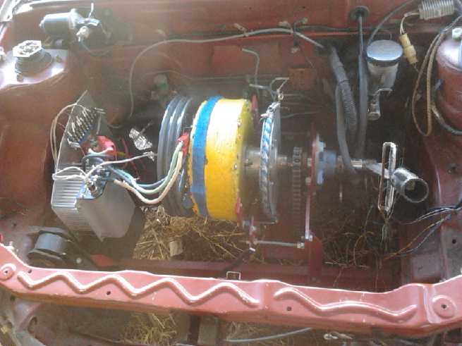
The double pulley flywheel.
At the hexagonal far end of the drive shaft, a torque wrench is used to
determine how much torque is required to move the car ahead or back
from the position it's presently in. When it can climb slopes that
require
40-50 foot-pounds, it'll be strong enough for the street. 10 foot-pounds
has been doubled to 20, but it needs to be at least doubled again.
That's
probably attainable with adjustments.
I shot some good video footage of some of the tests, but I haven't had
time to put it together into a movie.
The main problem with reverse seems to be that even in
"P",
there's still some tension on the pulley that isn't there in forward.
That load prevents the motor and flywheel from spinning up sufficiently
for a good starting boost.
I'll see if it can graduate to still higher start-out
torques with adjustments and more practice. (One can't
drive a regular gas car with a clutch and manual transmission without a
bit of practice, either.) If it's good enough, I'll change the chain
sprocket to the differential from 4 to 1 reduction to 3 to 1, at
which point the motor won't over-rev (over 3000 RPM) anywhere on city
streets.
Adjustments, adjustments!
Conclusion
Even if the Sprint with PGTC probably isn't yet
streetworthy, April's progress was at least a qualified - and
heartening - success. In fact, other than trying various adjustments to
get better and smoother operation, the next jobs will be rather mundane:
* beef up
some of the mechanical parts so they won't come loose after some small
amount of driving.
* put meters in the dash to show battery voltage,
amps, and motor temperature.
Later and still before going on the street, it'll still need some more
battery
capacity (300+ amp-hours) and more "mundane" things:
* reconnection of the speedometer cable to the differential in the PGTC
housing
* reinstallation of various car parts removed (rear fender, etc)
* repair of the
headlight circuits and reassembly of the dash (Why did I get into that?)
* adding an amp-hour meter to the dash (the "Link 10" from the Mazda?)
* adding an oil dripper or something to keep the
planetary gear and the chain lubricated while driving. (I guess canola
oil would work, and be environmetally benign? Maybe a cup to catch
dripped oil? Maybe later switch to a toothed belt? And to some nylon or
UHMW-PE planet gears?)
"Permanent
Magnet Assisted" Unipolar Motor?
One vital question I have
about
the electro-permanent magnet motor idea is, how much energy does it
require to magnetize the AlNiCo-5 magnets? Obviously, if it took more
energy in the fast pulse to magnetize at turn-on time, then demagnetize
it at turn-off time, than to keep a regular electromagnet energized
throughout, it wouldn't save energy. And this is dependent on how
often it has to be switched on and off, which depends on the RPM and
the number of stator poles.
There is the possibility of making some form of BLDC4-3
motors like or almost like the Electric Hubcap and running them with
the unipolar motor controller. As long as the RPM.s are relatively low,
an electropermanent magnet solution might save substantial energy.
But I wanted to make reluctance motors, partly for their
potential for very high RPM running, and my ARM motor gets its torque
by
having many overlapping rotor poles. Both of together these mean far
higher magnet on-off switching speeds, the worst case for the
electro-permanent magnet idea. The ARM motor is thus about the least
likely candidate for saving energy as an electro-permanent magnet
machine.
Admittedly I have no figures for any of this, but below is
yet another new option for getting higher performance out of a motor.
My feeling is that it would be just as good or better for the ARM
motor, tho maybe not for the lower RPM BLDC4-3 with fewer rotor poles.
On the 3rd Leonardo, always a great sender of the most
interesting info, sent me a link to a motor made before 2006 in which a
cylindrical supermagnet was placed inside a toroidal soft magnetic core
-- much like my toroidal motor coil cores. With 'keepers', the
supermagnet field is said to be shorted through the soft magnetic core
and have no external effect. (That seems odd when there's no opposing
magnet like with the electropermanent configuration, but that's what is
being said for both types. Maybe it's "less perfect" than the other?)
But if the coil
is actuated, the supermagnet and coil electromagnet fields are
additive, so the field is stronger than with the electromagnet alone.
Again, we seem to be getting "something for nothing", or at least
getting more flux with lower current and losses than normal.
Another video had a home-made test motor. Assisting
supermagnets could be placed on the coils by hand with the motor
running to see what difference there was, if any. It seemed to show
that it worked much the same with no load with or without the magnets.
I thought he was about to debunk the whole idea and show it didn't
accomplish anything. But with the motor running under heavy load, when
the magnets were set in place, the current meter dropped from 4 amps to
2 amps with the same load, while staying at about the same RPM.
Wow! That would be a great energy savings in an EV! In it we start to
see potential for a 500 mile daily cruising range. (I don't think I've
ever driven that far in a single day myself.)
What's really appealing to me is that this system would
mean using the same unipolar motor controller I've been developing. And
since I could do the magnets the same way in my motors, it would seem I
could just add 6 magnets to my unipolar motor and get the better
performance out of the same motor.
I ordered some, 25mm O.D. by 20mm long, and they arrived
on the 18th. That size leaves 5.4mm height/thickness for inserting
1.25" O.D. "keeper" circles without raising the height of the coils,
with the steel base of the motor being the other end's "keeper". Now,
people have been mentioning "mu-metal" as being a better magnetic
conductor than steel for those keepers. And I was given 3 old hard
drives, said to contain it. I'm dubious about finding a 1.25" piece 5mm
thick, let alone 6 of them. When I looked up mu-metal, I found
permalloy should be even better, while supermalloy was probably tops.
But were they really necessary? It didn't really sound
like it, and I didn't fancy my chances of finding any of them at Metal
Supermarket. Maybe I could just find some 1.25" O.D. washers, in any
kind of soft magnetic material? I found a 1/4" (I.D.) "fender washer"
in my collection, but it was much too thin, and then I figured, it
really needs to be one piece. Multiple layers interrupts the magnetic
flux.
Then it occurred to me that instead of trying to cut
"perfect" disks out of steel plate, I might cut them off the end of a
1.25" O.D. steel rod to the desired thickness. Ya, that was it!...
using somebody else's power hacksaw. But if I cut them roughly from
plate, say with the jigsaw, I would cut them slightly oversize and then
I could turn them down to circles on the lathe, and at the same time
put in an upper lip that would follow the rounded top edge of the
toroid
coil for a better fit. Sigh, that's probably the way to go. Now we have
not only finicky plate cutting with a slow jigsaw, but finicky lathe
work following that!
Unipolar
Motors "Breakthrough"? Oops.
In thinking about the flux, on the 4th a possible reason
the 'unipolar' Electric Caik motor doesn't seem to have as much "oomf"
as I expected occurred to me. The coils themselves don't care about
magnetic polarity. They carry their own field through the ilmenite, and
behind them is plastic laminate. the supermagnets have their own
polarity. But the rotor disk backing the supermagnets is steel. Both
coils put "north" towards the rotor, which is bound to weaken the flux.
If one coil was north and the other south, things might work out
better. The field would flow across the rotor from one side to the
other as well as through the rings.
The trouble was, if one coil was changed to the opposite
polarity, it would try to turn the motor the opposite direction to the
other and nothing would happen. First I thought of having an odd number
of magnets on the rotor so the polarities would be opposite. Duh... one
side would be between magnets while the other was dead on one! That
wouldn't work. Besides, with an odd number, two consecutive magnets
somewhere would have to have the same polarity.
The other possibility was that the stator coils be offset
so that when one is between a NS pair on the stator, the other is
between a SN pair, on almost the opposite side of the rotor.
Then they could have opposite polarities and yet both add to the
rotational force in the same direction. That would be a considerable
modification to the stator layout, and might cause a fair bit of
vibration when running. If there were 4 coils per phase instead of two,
the offsets could cancel out. That's a somewhat bigger motor than I've
been building. But three coils per phase with only one phase on at a
time, the Electric Hubcap size,
would be magnetically unbalanced.
Perhaps the easiest way to test the theory would be to
disconnect half the coils and try just one coil per phase. If it has
more than 1/2 as much torque as two coils (with the same current), it
probably means opposite polarities should be put to the rotor. If not
there'd be no point building a special motor.
Then I came to the ARM reluctance motor... In theory the
ARM motor wouldn't care about coil polarities because the rings around
the coils conduct the field. But I had a suspicion it would work a
whole lot work better if one coil was magnetized in each direction.
Unlike the BLDC's rotor supermagnets, the steel rotor doesn't care
about coil polarity; it's attracted to both north and south - nothing
repels. So reverse polarities with each pair of coils would be easy
enough to try simply by reversing the wires on half the coils. (In the
cramped space - easier said than done. Oh well!)
I have a hunch using opposite coil-pair polarities will
make a big difference on both unipolar motors, but especially the ARM
motor. My first reluctance experiments had no rings around the coils,
and it certainly performed night and day better with opposite polarity
coils. But the rings probably don't carry all the flux, so some would
still go across the rotor. On the 6th I disassembled the motor and took
it to the garage where I could use the propane torch for soldering. I
un-wired half the coils and connected up their wires the other way
around.
The results surprised me. It seemed to work no better. The
torque was certianly no higher, and indeed the RPM only went half as
high. Then I belatedly checked with a magnet. All six coils were now
the same polarity. Apparently I had originally wired them oppositely...
and then forgotten that I had done so... and now, probably thinking of
the Caik motor which had to have like polarities, so completely assumed
they were that I hadn't that I didn't even
check before rewiring them.
So I proved that it does work better with opposite
polarity coils, by changing them to like polarity and observing that it
works worse. Next I have to spend more hours on it, putting all the
wiring back the way it was! To make matters worse, the high currents
had managed to damage my lab power supply, so that it too needed
repair. One step forward and two backward. Curses! (The power
supply turned out to be merely a bent relay contact arm. The voltage
selection relay had been flicking on and off rapidly with each current
pulse, and finally had had enough.)
When the motor was rewired I could throw in the neo
magnets and have it "permanent magnet assisted" quite easily. The one
thing was
I would need to make six 1.25" "keeper bar" circles from 3/16" steel
plate, and probably some plastic spacers to center the magnets in the
coils. Then everything would have to be epoxied in place.
Slipping
Clutch Belt Vehicle Drive Idea - an improvement?
I thought of a potential improvement for the slipping belt
drive, perhaps thinking of how the rope in the Sprint car was behaving.
If the flat belt itself was "stickier" in one section and "slipperier"
in the rest, it would tend to slip more easily over most of its
circuit, then somewhat "grab" as the stickier part went by the small
pulley. This would give the motor a chance to speed up, then apply its
energy to the car wheel, via its flywheel, in the stickier section. I'm
not sure how this would work out in practice. For one thing, the belt
might just stop when the 'stickier' section is on the large pulley.
Then the motor would just spin. (Two sticky sections at opposite
points? Instead, a section of the drive pulley "stickier" than
the rest?) Anyway, it seemed like an interesting theory that might
warrant an experiment at some point.
But some of these things seem to just cause vibration. The
impetus during the push phase doesn't get things going. A much longer
period more push/less push cycle, like the flywheel in the torque
converter, seems to work well.
Turquoise
Battery
Project
-
New
Chemistry
Battery
Making
Self Discharge: Probably Caused by Graphite in the Positrode
It is perhaps so taken for granted among battery makers
that it is virtually unmentioned in the literature: It took me 3 years
to learn that at lower than pH 14, all metals including nickel will
oxidize in a positive electrode. This has been the raison d'etre of
alkaline battery chemistries, where nickel or nickel plating can be
used for positrode current collectors. The only material that will
stand up at lower pH.es is graphite, carbon. This is again implicitly
assumed, seemingly without ever being stated, in literature on lithium
batteries and fuel cells.
But ever since I got cells that worked, they have been
plagued
by high self discharge from an unknown cause. In the 2.6 volt
nickel-manganese cells I attributed it to the high cell voltage,
although at one point I figured I had traced the discharge to the
nickel hydroxide positive side rather than the high voltage manganese
negative.
So I thought I would make 1.2 volt nickel-nickel cells,
but once I got them working (in potassium sulfate electrolyte), they
seemed to also have the same self discharge. Thus it was virtually
certain it was the plus side, since it was the one thing still the same.
This month I decided to try something else again, and
replace the nickel hydroxide electrode with air, oxygen. Oh no, it
STILL has the self discharge!!! What's left? Just the graphite
conductors!
But I also learned in looking at graphene based conductors
that one evidently wants graphene oxide ("GO") based conductors
in the
positive electrodes. There's the key. With enough charging current for
a long enough time, the surface of the graphite starts to oxidize and
the self discharge eventually slows. I think I got this result 2 or 3
years ago. In cells that lasted long enough, the self discharge
continually reduced itself over weeks of testing. But I haven't tried
any cells for long enough to
see the effect recently, and the significance was forgotten over time
until now.
A better way to oxidize the surface of the graphite is
probably to douse it with hydrogen peroxide before using it in the
cell, and I plan to order some strong H2O2 in the near future for this
purpose. (May 6th: My brother has suggested bleach, and a youtube video
last night gave me the idea of using potassium chlorite or chlorate
(stronger than bleach).
Probably there has been all along nothing wrong with any
of my battery chemistries - nickel-manganese 2.6v, nickel-nickel 1.2v,
or air-nickel ~1v ... except for the failure to properly or adequately
oxidize the surfaces of the graphite in the positive electrodes.
I am writing this note on April 30th, having come to this
realization (or at least my conclusion at the moment) only in the last
days of the month. Much of the report below deals with the headaches of
attempting to eliminate the self discharge without having a grip on its
real cause.
News Report Confirms that Jelled Electrodes make for Virtually
Indefinite Cycle Life
Readers especially of earlier issues of TE News will
recall that I have been trying to gel electrodes in one way or another
since I started trying to develop batteries, even to the present cells
with glycerin, in order that they may last 'forever', or at least far
longer than present day cells. Here is a recent news article that
supports the
idea:
http://www.theweathernetwork.com/news/articles/scientists-accidentally-make-batteries-that-last-a-lifetime/66934/
Cheryl Santa Maria
Digital Reporter
Monday, April 25, 2016, 4:37 PM
-
California-based researchers have developed a nanowire-based battery
material that can be charged hundreds of thousands of times. This could
eventually lead to commercial batteries for computers, smartphones,
appliances, cars and spacecraft that may never need replacing.
A typical lithium-ion battery has a lifespan between 300
and
500
discharge/charge cycles for commercial products, according to
manufacturers.
After that, the filaments eventually grow brittle and crack.
But
by coating gold nanowires in a manganese dioxide shell and encasing it
in a gel, researchers at the University of California, Irvine (UCI)
have managed to make batteries last far longer.
A coated
electrode was tested up to 200,000 times over three months without
losing any of its capacity or power. For perspective, charging a
battery once a day, 200,000 times, equates to about 547 years of use.
Another interesting revelation of the article is something probably
most people have been experiencing: that lithium batteries typically
don't last anything like the many thousands of charge cycles often
touted, or even 10% that long, and are in fact no better than
nickel-metal hydride or even lead acid 'golf cart' batteries with
sodium sulfate added.
I write this note too on April 30th, having just been sent
the link by Jim Harrington.
Conductive Carbon/Graphite Rods
I sometimes amaze myself, as I suppose we all do, in
suddenly seeing that the answer to a problem has been right in front of
my face all along. I've looked in vain for local sources of carbon
rods. Finding nothing suitable, I take carbon/graphite rods out of old
dry cells, and think "Okay for a prototype or two, but what about
production?"
On the 10th, after all these years, it suddenly occurred
to me to look on line. Even "Graphite Store" where I ordered "flexible
graphite" sheets from before has conductive graphite rods! (did I
not see them?) A graphite company in Chicago had some too, at better
prices.
I ordered a bunch, in 3 different diameters, and they
arrived shortly after I had decided to try something completely
different - air-nickel cells - that would use no graphite rods.
Notes on the Nickel Negative Electrode
(Note: the following 2 sections are pre the Nickel-Air idea and pre
finding that the graphite surfaces have to be oxidized.)
The posode is regular nickel hydroxide charging to
nickel oxyhydroxide. (If potassium permanganate (better) or else
manganese dioxide is added, it will charge and discharge to various
nickel manganate forms that will gain and lose oxygen or hydroxides.
That's more conductive and holds more charge than NiOOH.) Anyway, these
are both no different to many others except for using current
collectors and conductivity additives of graphite/carbon/carbon black
instead of nickel metal, which would oxidize away in salt solutions.
The negode starts as nickel metal particles, discharging
to nickel hydroxide. This reaction wouldn't work at pH 14 where nickel
simply will not oxidize, but it will work in salt solution, at any
lower pH. For some reason I have finally found out that for nickel it
has to be sulfate
salt rather than chloride salt. The salt solution gravitates to about
pH 12 or 13 and so the reactions are essentially the same as alkaline,
with slight voltage shifts but in the same direction in both electrodes.
It *could* start as nickel hydroxide and be charged to
nickel particles, but I think it's better, or at least easier, to start
with nickel, the charged state.
So one can use a cupro-nickel, monel or (less preferred)
nickel-silver sheet current collector, nickel wool to make the whole
electrode very conductive, and press in fine micro nickel (or monel)
powder to give the most possible exposed nickel surface area. Of
course, one
might profitably add a sprinkling of nickel hydroxide powder to the
nickel powder. It
might improve the capacity.
Only the surface layer exposed to the
electrolyte reacts, leaving metal underneath untouched. Etching in
ferric
chloride roughens the surfaces at the nano or micro scale to increase
the surface area. The copper in the Cupro-nickel, monel or
nickel-silver etches away faster than the nickel (and the zinc in the
"nickel-silver" (better name: nickel-brass) etches even faster),
further increasing the exposed nickel content of the surface area of
the sheet metal.
The reaction voltage of copper is lower than nickel, so
the copper in the alloy always stays in its metallic form unless the
cell is drained down to nothing.
Self Discharge - Grrrrrr!
When I was making Ni-Mn cells that charged to 2.6 volts, I
assumed it was hard to prevent gradual (hours to a day or two) self
discharge because of the high voltages within the cell. It's one reason
I quit working with that chemistry. When I tried Ni-Ni, the other
highly promising chemistry I identified long ago, I got an unknown (to
me, anyway) rapid and continuous self discharge reaction, apparently
between the KCl electrolyte and (presumably) the nickel negative. It
didn't work worth a darn! That took me aback and I left batteries to
work on other things. After a long time, an inspiration finally came
along: try another electrolyte. Ni-Ni in K2SO4 works fine, but I find
even the low voltage (1.25v or so) cell having similar gradual self
discharge to Ni-Mn.
 On the 7th I
got around to putting the electrodes, with
the impurities presumably diluted out, back into the test jar/cell and
added some fresh potassium sulfate. I noticed the jar with that
electrode and a couple of other carbon terminals had fluffy orange
precipitate filling the water. I'm not sure what that is, but I've seen
it in test cells before. Really, another dilution should have been in
order. But surely most of whatever it was was gone from the electrode.
(When it was refilled with fresh
water, the remaining carbon electrodes produced no more of it. Must
check the cell to see if it produces more.)
On the 7th I
got around to putting the electrodes, with
the impurities presumably diluted out, back into the test jar/cell and
added some fresh potassium sulfate. I noticed the jar with that
electrode and a couple of other carbon terminals had fluffy orange
precipitate filling the water. I'm not sure what that is, but I've seen
it in test cells before. Really, another dilution should have been in
order. But surely most of whatever it was was gone from the electrode.
(When it was refilled with fresh
water, the remaining carbon electrodes produced no more of it. Must
check the cell to see if it produces more.)
When even a small charge was connected, the voltage jumped
from .2 to .9 in a couple of seconds. It hit 1.25v in a couple of
minutes of ever slowing rise. Now that sort of immediate jump up from
nothing to somewhere near the expected voltage is more like a real
battery! It continued charging at 2.5mA and in 15 minutes hit 1.44
volts. Well, it's not much of an electrode. In an hour: 1.56v. 2 hours
brought it to just 1.57 and 3 to 1.58, so I guess it was still
charging. I took it off charge. When I came back an hour or more later
it was way down below a volt.
I put it back on for about 4 hours, then off at 22:30PM.
It had reached 1.6 volts. An hour later it was at 1.37 and losing a
little faster than a millivolt per minute. It really wasn't much
different than before the cleaning.
By the 10th I decided to
work exclusively to tackle the
self discharge. It was really the key problem, and unless I could get
rid of it or at least reduce it to insignificance, I was never going to
have practical batteries. But what was its cause? It seemed to be more
or less the same both for NiMn (in KCl) and for NiNi (in K2SO4).
For the negatives I had fairly pure nickel and
cupro-nickel. The cupro-nickel apparently had a bit of iron and
manganese in it, about 1% total. Any exposed manganese would
self-discharge to insoluble Mn(OH)2 and thereafter be inert. The same
could be said for iron, permanently discharging to Fe2O3 (or Fe2(OH)6
or something) since the pH is less than 14. .05% zinc might charge and
discharge, and cause the voltage to be somewhat higher with a very
fully charged cell, but not for long once any current was drawn. Other
impurities listed were in vanishingly small quantities.
Surely the electrolyte, KCl for the NiMn chemistry and
K2SO4 for the NiNi, couldn't be the culprit. Not when they were both
seemingly pure, and yet both cells had the same sort of self discharge.
That seemed to leave the positrode. It's the part that's
the same for both chemistries. One might blame one of the additives
like the Sunlight dishsoap or the samarium oxide... except this time I
hadn't used any additives at all. All that was in this electrode was
the carbon rod, active pure Ni(OH)2, and conductive carbon black. And
the carbon black was something different than the graphite powder I was
using earlier, yet the self discharge still seems similar. I've also
used various forms of carbon rods, sheets, and "graphite foil"
seemingly without curing the self discharge. I will of course buy and
try out some of the graphite rods mentioned above. Of course in the
lower pH, the NiOOH has a higher reaction voltage than at pH 14. Maybe
it *has* to have some oxygen gas suppression additive or additives,
like the samarium oxide. If so, maybe without it, it would work better
at fridge temperature? There's an easy experiment to try!
And of course, watercolor paper wraps it all up, with
plastic cable ties. Yikes... the paper?!? there is another common
ingredient to all or nearly all my cells. Hmm... Didn't my first Ni-Mn
test cells in February 2012, using perforated plastic "pockets" - and
no paper - have virtually no self discharge? Or was I just so thrilled
they worked with little self discharge that I paid it no
attention? I'll have to try PP fabric(?) with no paper.
Whatever was causing the self discharge didn't seem to be
diluted out by putting the electrodes in pure water. Perhaps I should
try diluting it in solvent - toluene (methyl benzene) of course comes
to mind. I looked this substance up again on Wikipedia. Unless my
memory is wrong (easily possible of course), it used to say toluene
dissolved graphite to make carbon nanotubes. Now it says it 'dissolves
carbon nanotubes'. A '.edu' source says graphite (among other things)
won't dissolve in anything it doesn't chemically react with - the
molecular bonds are too strong. I did find that a treatment with
toluene (or "Diesel Kleen") made the electrodes about 40% more
conductive, whether because of dissolving the graphite powder, chemical
alteration, or simply by the graphite particles floating around and
re-aligning themselves in lamilae and other favorable patterns, I don't
know. (Diesel Kleen is good for wiping up spilled carbony/graphity
messes that nothing else seems to touch, even once dried. I guess
the graphite must react with it.)
A small quantity of toluene wetting the electrode, while
improving the conductivity, never seemed to do anything for the self
discharge. This time I immersed the whole electrode in a jar of it. At
the risk of possibly dissolving out all the carbon black and eating
away the carbon electrode?
I let it dry out, put it in toluene for a while, let it
dry out, and put it back in the cell on the 12th. By the next day it
was apparent that it was somewhat better, still 1.38v after 2 hours,
and losing about 2/3 mV/minute - a third slower. After 4h15m it was
down to 1.20v.
As I went to put it in the fridge it tipped over and I had
to refill it and put the modelling clay top back on. I put it back on
charge in the fridge to see what would happen. Later I removed the
charge, but the self discharge seemed about double, ie taking half as
long. Not what I was expecting! I took it out and noticed there was
quite a gap in the cover, between an electrode and the rim. And the
discharge was even faster than in the fridge, even with the gap
somewhat covered. There seem to be some unknown factors - or change
over time or cycling. But what? I opened the cell and found the paper
had unraveled at the bottom and spilled out some of the positrode
substance, which lay on the bottom and may have been touching both
electrodes. That solved that mystery! I decided I'd flogged about all I
could out of the little test cell.
Air-Nickel Battery?
The Ni-Mn (2-1/2v) cells had the high self discharge. I
originally attributed it to the high reaction voltage of Mn metal, ~
-1.5v. Then the Ni-Ni cells, half the voltage, didn't work at all until
I changed from potassium chloride electrolyte to potassium sulfate. (I
still don't understand why KCl doesn't work.) But these lower voltage
cells had seemingly identical high self discharge to the others. That
meant it had to be coming from the plus electrode common to both of
them. What else but nickel hydroxide or nickel manganate might one use?
Silver oxide is another alkaline positive, but it's less than
economical and it too might have problems in my cells.
From time to time I've
heard of air - meaning the oxygen in the air - as a type of electrode.
Somehow the thought of an air electrode crept into my thinking.
In most cells, the main metal of the posode is given
first, then that of the negode. For some reason, when the positive is
an air electrode, this gets reversed. Instead of air-zinc, it's usually
called zinc-air. Being stubborn, I'm presently calling the new idea
with the older convention, air-nickel. Also, calling it nickel-air
might confuse people into thinking it's a nickel oxyhydroxide posode
rather than a metallic state nickel negode. And then what is in the
"air" as a negode instead of an oxygen posode?
The half reaction, at the interface between gaseous oxygen
and liquid water, is:
O2 + 2 H2O + 4 e- <==> 4 OH- [at about +.40v in
alkali - I think.]
That voltage is lower than the nickel oxyhydroxide
reaction in sodium sulfate. The four OH- ions behave in the usual way
to react with the negatrode:
2 Ni + 4 OH- <==> 2 Ni(OH)2 + 4 e- [at -.72v at pH 14]
Those voltages both head in the "+" direction with
decreasing alkalinity, so the voltage at slightly lower pH is likely to
remain at about 1.1 volts. That may seem a little low, but 2/3 to 3/4
of the cell weight and considerable bulk is eliminated by the absence
of posode active substance. So even adding a few extra cells to get a
particular voltage is going to cut weight and internal size for a given
voltage
and storage capacity.
People have seemed to have various issues with air-metal
cells and I haven't yet heard of what sounds like a really practical
rechargeable one so far - certainly nothing that I've heard of has come
onto the
market.
But what are the issues? One keeps hearing of air-zinc.
Zinc is always a problematic metal for rechargeable batteries since it
gradually dissolves, and usually forms dendrites that grow through the
separator and short out the cell. Cadmium has the same problem to a
lesser degree. Iron has been or is being tried, but has low
conductivity and tends to clump up with cycling, losing surface area
and capacity.
Metal hydride might work well, but I haven't heard of anyone trying to
make air-metal hydride. (Perhaps it has to do with all the patents
Chevron has acquired on metal hydrides to stop people from making Ni-MH
batteries big enough for transport?)
Other than finding a good choice of metal, mainly it seems
it's hard to control the humidity of the cell when one of the
electrodes is exposed to the air, and to prevent infiltration of carbon
dioxide. But it may be that we can get around those problems. First,
nickel seems like a great choice of metal. No one else has tried it
because metallic nickel, uniquely, doesn't work in potassium hydroxide
electrolyte, which is almost universally the chosen one.
Then, carbon dioxide gradually turns potassium hydroxide
electrolyte into potassium carbonate. With potassium sulfate as the
electrolyte instead, perhaps CO2 will be much less of a problem? OTOH,
the reactions are still alkaline, and the nickel may be
susceptible to
being turned into nickel carbonate, which is probably an insulator that
won't recharge.
Low density polyethylene film blocks liquid water while
allowing
oxygen gas to penetrate. What if one simply had an LDPE film encasing
the
entire cell? And then what if there was a water reservoir that could be
filled if the cells should gradually dry out?
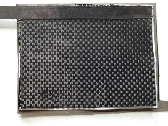
Graphene or Graphene Oxide Layer on Plastic Film
What about a positrode conductor sheet? It has to let the
oxygen molecules pass through from the air into the liquid, as well as
conduct the electrons from the reactions. I recalled that someone I'd
seen on Youtube had found a great mechanical way to make graphene
sheets. This turned out to be Robert Murray-Smith, who has a fantastic
assortment of technical videos with a lot of great new ideas. His
method involved graphene powder, very fine sandpaper, rubber blocks,
and polycarbonate (lexan) plastic. His very first one read just 1 ohm
between
random points on his meter! A couple of updates to the technique,
forming the graphene on glass with an orbital sander and soft cloth
instead of sandpaper looked even better. If I could make it on LDPE
instead, it should allow oxygen through, and also repel water to keep
it inside. Maybe that's a magical front surface for an air electrode?
And maybe finding the right density could even allow O2 through freely,
but block CO2 (which I would hope is a larger molecule?) if it even
matters.
 I decided to
try making a graphene layer on a piece of
LDPE film. If that worked okay, I might try doing an air-nickel cell.
First I made a comment on his video explaining what I was going to try,
to see if he might have any suggestions.Then I went ahead and tried it,
using a thin piece of PE window film from a pie package/box and
conductive carbon black. The carbon wouldn't rub into the plastic.
Either PE doesn't work or carbon black just isn't the same thing as
graphene. I added a few drops of toluene, but it didn't help. The
plastic stayed clear and was above 2 megohms resistance. Only the
napkin I was rubbing with gained something of a black sheen. Well, I
had a feeling it wasn't going to be that simple! At least the plastic
didn't rip, or even stretch much. On the 21st I bought a 1/16" 'rigid'
sheet of the plastic used in the video, polycarbonate (which turns out
to be the 'real' name for "lexan", although polycarbonates can have
various formulas), and tried on that... with about the same results.
But it seems from Wikipedia that polycarbonates are also somewhat
permeable to oxygen. Specs are given for it, but there are none for
polyethylene, so I can't compare them.
I decided to
try making a graphene layer on a piece of
LDPE film. If that worked okay, I might try doing an air-nickel cell.
First I made a comment on his video explaining what I was going to try,
to see if he might have any suggestions.Then I went ahead and tried it,
using a thin piece of PE window film from a pie package/box and
conductive carbon black. The carbon wouldn't rub into the plastic.
Either PE doesn't work or carbon black just isn't the same thing as
graphene. I added a few drops of toluene, but it didn't help. The
plastic stayed clear and was above 2 megohms resistance. Only the
napkin I was rubbing with gained something of a black sheen. Well, I
had a feeling it wasn't going to be that simple! At least the plastic
didn't rip, or even stretch much. On the 21st I bought a 1/16" 'rigid'
sheet of the plastic used in the video, polycarbonate (which turns out
to be the 'real' name for "lexan", although polycarbonates can have
various formulas), and tried on that... with about the same results.
But it seems from Wikipedia that polycarbonates are also somewhat
permeable to oxygen. Specs are given for it, but there are none for
polyethylene, so I can't compare them.
Only on the 'magic transparent' tape that I held the
pieces down on the glass backing with did the carbon black 'stick',
yielding resistances in the lower 100s of kilohms between any two
points. I rubbed one piece specifically and it dropped into the mid 10s
of kilohms. Those values were too high to consider using, so that
simple technique wasn't going to do the trick with the tape, either.
Next I tried adding a few drops of sulfuric acid (SG 1.25
battery acid strength), on both surfaces. The friction when rubbing
went way up, and a smear of carbon could be left behind. But it didn't
build up with successive passes. I added a few drops of hydrogen
peroxide, but aside from a tendency to bead up at first, that didn't
help either. Where I left smears, the resistance went down a little
below 2 megohms - to where the meter could read it. But the smears
could be wiped off again. I decided that was it for the evening.
Next I started looking over some of the other videos and
info again, about making graphene and graphene oxide suspensions and
related things. It's starting to look like I'll need to get into making
graphene or its oxide form, involving some rather complex chemistry
with chemicals that should be simple to buy but are probably banned,
and some special equipment like an ultrasonic heater-stirrer, if I
really want to pursue this. Or perhaps, at least for a few experiments,
purchase it at what seem like exorbitant prices for tiny amounts.
Rethinking It!
On the 22nd I started rethinking the actual requirements,
and by the morning of the 23rd I woke up with the realization that
there's no real need for the graphite to be bonded to the air-permeable
film. They don't really even need to be in contact at all. Perhaps it
would be better to layer the battery as:
- the permeable film (on top or "front")
- a sheet of carbon/graphite fiber, electrode and current conductor.
- electrode separator sheet
- nickel foam & powder in a gel (glycerin)
- cupro-nickel (bottom or "back"), current collector and negative
terminal
The fiber could be impregnated with carbon black or graphite powder if
it's useful for interfacing with the oxygen in the air to improve
current capacity. All along one edge, a strip of graphite foil would
contact the graphite fiber and stick out the top. This would be the
positive current collector and positive terminal connection. There
would be some plastic, 'weatherstripping', glue, wax, or other means
for sealing around the edges. Cells could be stacked beside each other
in series and held in a frame, with the graphite foil of one cell
touching the cupro-nickel of the next.
This new carbon fiber idea seems not only much superior,
but far easier to accomplish. Perhaps I've been watching too many
youtube videos about making graphene, graphene oxide, and making
conductive layers on sheets! In fact, if it goes according to plan,
with carbon fiber this looks like much the the easiest battery I'll
ever have tried to make. How many years have I been doing this without
ever considering using an air electrode? It all shows how you can miss
better ways to do something by focusing in too closely. Step back for a
broader perspective!
Nickel Advantage?
The nickel negode might here be a definite benefit over
most any other metal. Most alkaline negodes will self-discharge if they
come in contact with oxygen. In fact, it's how NiMH and NiCd sealed dry
cells stop charging when they're full. Oxygen gas is given off at the
posode and drifts over to the negode. The oxygen discharges the metal
to oxide/hydroxide preventing overcharging, and the reaction starts
heating it up.
So I presume that the air-metal cells have to be flooded
cells, with the air electrode layer dry on one side and immersed on the
other, asking a lot of such an interface layer. Simple carbon fiber
would be "out".
But the nickel cell could be essentially unaffected by
ambient air, much as is lead-acid. I don't think gaseous oxygen will
cause a
corrosion/oxidation reaction to nickel without an external circuit
taking electrons. Nickel's reaction voltage is lower, and it's notably
corrosion resistant to salt. If this proves to be the case, I expect it
would give air-nickel a tremendous advantage over all other air-metal
based batteries that have been tried so far. That means it just might
succeed and prove practical where other rechargeable air-metal cells
have failed to make it to market. And (even without doing calculations)
a nickel-air cell should at the very least give lithium types a run for
their money in terms of capacity per weight and current density.
Cell Design & Humidity: moisture level maintenance
I didn't expect to be able to achieve perfect water
retention. Surely the cells would gradually dry out in spite of the low
rate of passage of H2O through the plastic sheet. So, turn the whole
frame sideways so all the cells are oriented vertically. Somewhere in
the bottom corner of each cell would be a pocket for water, with a
transparent window on the edge, and a means for refilling it, also
along the edge. My hopeful thought of how this would work was that when
the pocket was empty of water, it would mean the cell was drying out
and more should be added to fill the pocket. They would be "dry cells"
in that there'd be air inside. One would occasionally inspect the whole
frame and refill any cells that were getting dry.
But then I learned something new. It started with an old
mystery... Once upon a time (a year ago?) I opened the door to my dry
chemical closet
and found water on the floor. Huh? It being my chemical closet I
checked the pH of this water and it was 14 - it was very alkaline
water! I had a plastic bag of sodium hydroxide on the top shelf at the
back. I dug it out and found the bag was open and full of water! The
water had run down the back wall from there and spread out. But there
was no evidence of a rainwater leak in the ceiling or any other source
of water. Why would anyone play such a bizarre trick with a dangerous
chemical? I started wondering about my renter, and locking the door to
my lab. I poured it out and discarded it,
mopped out the closet with a rag, and cleaned it all up. There didn't
seem to be much left anyway - why had I bothered saving it?
Now on the 23rd, I opened the closet to look for carbon
fiber cloth. There was water on the floor, little puddles, and a metal
can (my nickel powder) was wet and rusted around the bottom rim,
leaving a big ring of rust stain on the floor. Huh? It wasn't like that
last time I opened it - at least not that I'd noticed. I started
pulling things out both to clean up and hoping to find the carbon
fiber, as well as any clue to this new water mystery. This time the pH
was neutral. And the water was only at floor level.
Last fall I had purchased some calcium chloride salt (road
de-icing salt), and poured most of it into a plastic pail with a lid.
It didn't all fit, and I had left some in the paper bag inside the
plastic bag on the floor. But now when I looked, there was just a smear
remaining in the paper bag, which was sitting in 2" of water within the
plastic bag! The bag of salt was the source of the water! and the
reason for the rapid rusting!
I went to Wikipedia and looked up "hygroscopic" - attracts
water. From there I went to the extreme form "deliquescent", which
means it attracts moisture from the air so strongly it can dissolve in
the attracted water. Sure enough: calcium chloride and sodium hydroxide
are both deliquescent! I hadn't realized that meant a substance can
eventually absorb cups of water out of the air, even until a
plastic bag runs over and causes a small flood!
So I looked up potassium sulfate, all I saw was that it
said "unlike sodium sulfate, potassium sulfate does not form a
hydrate." It also said somewhere that ABS plastic is hygroscopic, which
may explain some of the things happening with my previous cells -
exuding salt and moisture.
Now, what does this mean here? At a guess, potassium
sulfate isn't hygroscopic, so it won't attract water from the air.
However, if it was mixed with a little sodium sulfate - or maybe
calcium sulfate or something else - it might attract just enough
water from the air to maintain a workable humidity inside the cell.
OTOH, developing this would require being able to measure the moisture
levels. Well, one could carefully record the cell's dry weight and
decide that
any additional weight measured later was water.
2 Test Cells
I purchased on that day (23rd) some yards of carbon fiber
cloth (Industrial Plastics) and some Avery "transparent labels" as
cover plastic (Staples). Everything else, I had. I quickly slapped
together a test cell. I didn't bother with edges, and it dried out
quickly.
Every time the soft looking carbon fiber cloth is cut, a
small cloud of fine dust comes off it, so fine it's barely visible when
cutting outside in sunlight. For days afterward I was getting stabbed
mostly in the legs, by micro-fine spears and when I looked there were
little red spots all over. Changing clothes didn't seem to help. I
really hate working with carbon fiber! It's probably as bad as
asbestos. If anyone is going to work much with it,
they should have a full fledged exhaust ventilation system and means
for minimizing handling and flexing.
On the 27th I found a bit of time to put together another
cell. This one I made twice as large, 4" x 3", and I decided to try to
put together a "proper" nickel electrode. I also used things I learned
form the first one, like to make the separator sheet a little bigger
than the carbon electrode so it wouldn't short circuit at the edges.
That's 77 sq.cm. At 50 mA/sq.cm, that would theoretically
be about 4 amps current capacity. But it might actually be able to
handle more current than that, since I once read of a zinc-air cell
that could do 200 mA/sq.cm without too much voltage drop.
I cut the cupro-nickel sheet a little oversize, and with a
connection tab sticking out one corner so I wouldn't have to lift the
cell off the table to connect to it. Then I cut a piece of nickel foam
the exact 3" x 4" size. I etched both of them for about 10 seconds. I centered the foam on the sheet.
 I mixed some
glycerin
and some nickel micro flake powder. As explained last month, glycerin
liquid should 'set' in an alkaline environment, which the cells will
have. It made a thick paste, which I
painted onto and into the foam. It was saturated with around 3.5 grams
of nickel flake - the bulk of the 5 grams I had put in the dish. (I
didn't measure the glycerin - maybe 3/4 of a teaspoon.) The foam was
about 2 grams, making 5.5. I discount the sheet metal since most of the
nickel substance is internal, unavailable for reaction. Nickel metal is
about 914
AH/Kg, so its theoretical maximum capacity is about 5.0 amp-hours. The
air/O2 side is of course unlimited.
I mixed some
glycerin
and some nickel micro flake powder. As explained last month, glycerin
liquid should 'set' in an alkaline environment, which the cells will
have. It made a thick paste, which I
painted onto and into the foam. It was saturated with around 3.5 grams
of nickel flake - the bulk of the 5 grams I had put in the dish. (I
didn't measure the glycerin - maybe 3/4 of a teaspoon.) The foam was
about 2 grams, making 5.5. I discount the sheet metal since most of the
nickel substance is internal, unavailable for reaction. Nickel metal is
about 914
AH/Kg, so its theoretical maximum capacity is about 5.0 amp-hours. The
air/O2 side is of course unlimited.
Resistance between the contact tab and any other spot was
about
zero ohms. Assuming the glycerin works, here's a perfectly conductive
electrode easily made with no hydraulic pressing or anything hard to
do. (It may however work best if compacted - to be determined.)
I pressed the separator paper (Arches 90# watercolor
paper) onto the electrode and put a flat weight on it to hold it down.
I'm hoping it will be rather "glued" to the glycerin once it has set.
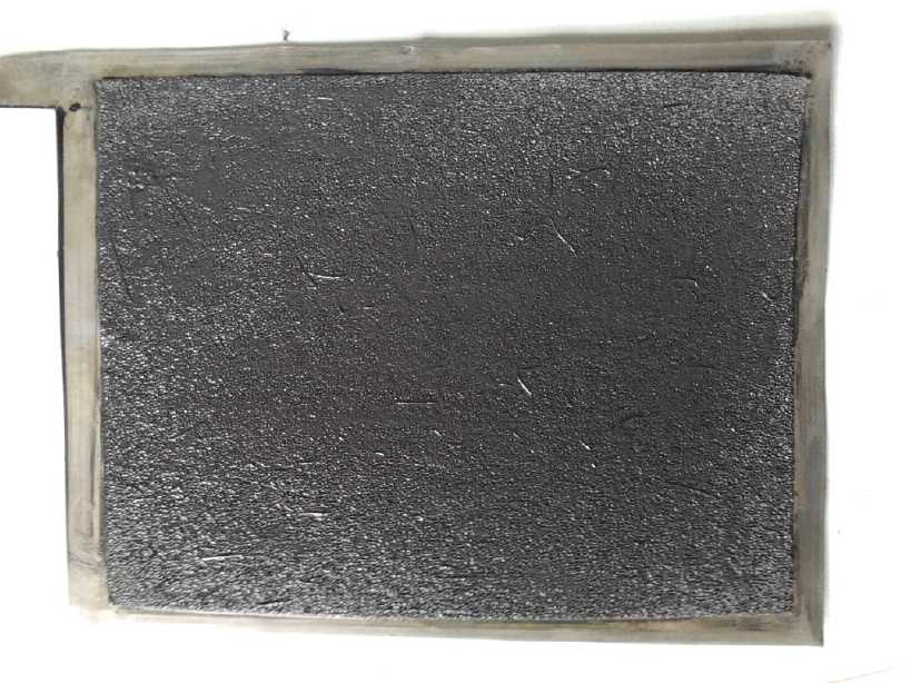 The nickel electrode
Base of cupro-nickel sheet 70:30%,
.5mm nickel foam sheet on that,
and nickel micro-flake in glycerin paste painted into the foam.
(Connection tab in corner.)
The whole Cell
On top of the nickel electrode:
90# watercolor paper (Arches) separator sheet
Carbon (graphite) fiber cloth conductive oxygen-water interface layer
Graphite foil current collector strip with connection tab
Adhesive, air permeable clear plastic label (glued to graphite cloth
and foil strip)
The top sheet was clear Avery label from an office supply,
a thin plastic which I hope is air permeable. I peeled off the backing.
First I stuck a long thin piece of graphite "foil" along one edge as a
current collector and terminal. Then I stuck on a piece of carbon fiber
cloth. I then trimmed some excess cloth away with scissors. As I had
discovered with the first one, even a thread you can't see can short
the graphite sheet to the metal.
I wonder if there's something one might paint the carbon
fiber with that would glue the fibers together, preferably before
cutting pieces off to make cells? But it's wet conductive fiber,
exposed to air, that has to carry the electrons and convert the O2 gas
+ 2 H2O into 4 OH2- ions in the water, to react with the nickel to make
2 Ni(OH)2. Sealing or insulating it just wouldn't do!
This time I had a plan for the edges to 'seal' the unit
and prevent the water from rapidly evaporating. I would melt beeswax
and drip it down around the edges to seal everything up. (Beeswax is
much stickier than parafin wax, which might simply chip off, and I
found some for sale recently.) Since I had
made the metal sheet oversize, it would all be dripping onto the sheet
and merely needed to cover around the edges of the top sheet, fiber,
separator and nickel foam, which were altogether only a couple of
millimeters thick.
The only question was how to get the electrolyte in. I
just left a small part of one edge open for that. It would
have to soak in through the separator sheet gradually from there.
I couldn't resist weighing the whole cell for the purposes
of idle speculation on potential specs. It was about 70g. Of that, 1/2,
35g, was the
cupro-nickel sheet. The cupro-nickel is very strong and stiff, and I
judge it could easily be made with sheets less than 1/2 as thick. Then
cells would weigh about 50g. If one really got a whole 3-1/3 AH out of
them, 2/3 of theoretical capacity, it would take 3 cells to make 10 AH,
weighing 150g. A 10 AH NiMH D cell weighs about 160g. Allowing for
slightly lower voltage, we might say that we can get almost the same
energy density by weight as NiMH dry cells, with a homemade nickel-air
battery.
But the nickel foam is only .5mm thick. It is probably
feasible to put on two layers of nickel foam filled with nickel powder
paste, or maybe even three and still get quite high current capacity.
Thus we
can double or triple the capacity with only about 6 or 12g added
weight. Triple would be 10 AH, weighing 75g, so 1/2 the weight and
double the energy density of NiMH. At that point, EV batteries start
becoming pretty lightweight. Of course, they need to be held in a frame
and spaced apart for air circulation. What would that make the storage
by volume? If one stacked the cells 8mm apart for adequate air flow
between cells (assuming that's adequate), that would be 88mm for 11
cells for 12 volts. Call it 10cm total for a stack of 11. Thus (with
the oversize back sheets) we have 4.4" x 6.4" x 10cm, or 11.2cm x
16.3cm x 10cm = 1820cc for a 10 AH 12V stack. (I would presume the
'racks' to hold them stacked would be 3-D printed.) Arrangements of 10
NiMH D
cells to get the same specs include those soldered together and put in
boxes, my 3-D printed boxes, and 1-1/4" PVC sprinkler pipes/tubes. The
3-D printed boxes are representative - 36mm x 132mm x 185mm = 880cc. So
it looks like about double the space is required for a battery weighing
1/2 as much. So they should be lightweight but bulky. But I digress.
After painting on some beeswax around the edges, I
squirted in some electrolyte with a syringe. The voltage went to -.07
or so. It seemed a little odd. The nickel was all in metallic form,
pre-charged. Surely there was oxygen in the air around. Why wouldn't it
just jump to about +1.1 volts?
The chief possibility was that the graphite fiber wasn't
really the right form. From the graphene info, it seemed graphene oxide
was desired. If I simply charged the cell with a low current, the
surface of the graphite might oxidize into the desired form, so I put
what should have been a charged battery on charge, just a couple of
milliamps. The power adapter charger connection quit during the night,
but on the 29th after a few hours on charge, it was holding over a volt
for a few minutes. Well, nothing for it but to continue and see how
well it formed up. Would it continue until the whole thing was perfect?
Probably I could pre-oxidize the carbon fiber surfaces
with hydrogen peroxide for future cells. I wanted to get some stronger
stuff than the 5% drug store variety, say 30% (the strength recommended
for the graphene), but it's amazing how little available anything that
isn't the most common can be. Sigh, I guess it'll be yet another a
pricey special order from a chemical company. Later I got ideas for
oxidizing with bleach or potassium chlorate.
Assuming it shapes up properly, this looks like it will be
far and away
the easiest battery to make at home. That it will have as high an
energy density as lithium types and should last forever are great added
bonuses!
http://www.TurquoiseEnergy.com
Victoria BC Canada