Turquoise Energy
Ltd.News #10
Victoria
BC
Craig Carmichael
-
December 3rd 2008
Contents:
November in
Brief
(overview... summary... the short version!)
* or, this TOC is the Super Short
version...
"Secret"
Federal SDTC
Program: Filling the Funding
Gap!
* Funding for developing clean
technologies
Electric
Hubcap Motor Making
Course/Workshop: Hybridize your
car (or other relevant motor project)!
* Cheaper, easier with only two motors
needed?
* starts, um... Feb? March?
Electric
Hubcap Motor
"Kit": Marketing Idea
* Sell manuals and parts
Electric
Hubcap Car Drive
Project, Very Longwinded Detailed Report
* Double
power
"production model" motor:
- probably just 2 motors needed per car
instead of
4!
- made from off-the-shelf automotive
parts!
Turquoise Battery Project, Very
Longwinded Detailed Report
* Effective Sealed
Battery Housings:
- plumbing pipes &
rubber test tube
stoppers!
* Convoluted battery chemistry... experiments
continue.
* Recent patents disclose battery work paralleling
mine.
November in
Brief
After many months of
trials and remakes with improving concepts and designs, October saw
the car finally move under electric power, driven at an unhazardous 36
volts by one tiny Electric Hubcaptm motor.
But it unless the
thrust of each motor could be significantly increased, it seemed that
all four wheels would need to be driven instead of just two. That
should work fine, but it would nearly double the expense and effort to
"hybridize" a car.
A better optimized
"production" version motor was designed, whose mechanical
components consist of proven, robust and widely available automotive
and trailer wheel parts. The off-the-shelf parts that all fit together
nicely were - at long last - all found in one week in October. With
the various minor improvements planned, it was hoped for 50-60% more
thrust, but at the start of November, estimates calculating all the
small gains together indicate that the thrust should be
double, and more than double at low speed when starting up
from a stop! Two motors could do the work of four!
Furthermore, a new
low-hertz pulse drive technique was conceived to put an end to the
wasteful runaway currents and resulting rapid heating that burns out
motors and controllers at very low RPMs when they must labour hard to
gradually start up from a stop. (and which had "taken out"
several of my controllers.)
Strangely, no one
seems to be applying this quite simple idea. As far as I can see,
instead of dealing with the problem, everyone uses a high RPM motor
and gears it down, simply trying to get the motor out of that
"annoying" low RPM range quickly. I myself almost decided to
substantially "beef up" the controller and coil wires before
I realized it wasn't necessary. Perhaps here is a glimmer of why no
one has previously done an ultra-efficient direct drive wheel
motor!
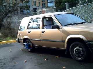
Car pulling out with 36 volts Electric
Hubcaptm
prototype in October
(movie URL below)
So in November, this
"double-power" second motor was undertaken, but withall I
didn't get it finished, the motor controller fixed, and the pulse
technique circuit made in time for tests for this
newsletter.
Funds could help to
get more things happening:
*
Parts for the 2nd Electric Hubcap "Production Prototype"
motor to get the car actually out driving on the
roads.
*
Possible approvals: CSA type approval on the Electric
Hubcap motors and controllers and automotive safety
approvals on the
system components.
*
Purchase of better chemicals (Dysprosium ingots, Osmium
powder) for batteries.
*
Development of:
- Electric Hubcap motor coil making
techniques
- Electric Hubcap electronic parts: motor
controller & optics,
- Driver's control/interface unit with
microcontroller & display.
Not producing whole
motors and complete installation kits is a liability advantage for a
starting-up company, car safety being a major liability issue: anyone
who assembles and installs their own motors should be responsible for
pretty much all aspects of their safety themselves and will have a
hard time sueing a manufacturer that merely supplied some of the
parts.
Movie Clips
(reprinted from last month - nothing new to show.)
At perhaps
1500-2000 RPM, this wheel has never before turned this
fast!
The pivotal
event!
(With extra
footage - the remote didn't turn the camera off.)
Finally I'll mention
that I'm getting a metal lathe, a most valuable tool for making many
odd parts. I wouldn't have been able to afford one, but someone I know
offered me one for an irresistable $300, disassembled, to get it out
of his house, and my mother (Thanks Mom!) has paid for it. I'll pick
it up near Courtenay at Christmas. I'm setting up a largeish room in
my house as a machine shop for motor making.
Canada's SDTC Clean
Technology Development Funding
Program
I've remarked before
that with what little support there seemed to be here for new
products, China would be more likely to bring out products based on my
designs than Canada (which we would then of course import), and in the
last issue I editorialized that inventors developing truly cutting
edge products seem to fall through the cracks in all the government
support programs, before having enough to show to attract even
adventurous "angel" investors much less venture capital, and
that I've heard less than one percent of inventors, after all their
unpaid labours, ever make good money off what they create. With
society and the government providing verbal encouragement but no
actual support (like a salary to live on while doing the work) through
the critical phases of product prototyping and development, most
people have to go out and get jobs doing something else in order to
live, rather than developing their concepts to marketability. Thus are
practical new products and technologies unknowingly swept under the
carpet unseen by the world, as we all wonder why so little that's real
and practical ever seems to come of promising concepts, demos and
ideas we see in the news.
Of course I am writing
my own impressions and opinions, but after doing R & D much of my
life and rarely getting paid - and then mostly to do other people's
projects - it has gradually dawned on me in the last year or two,
especially after talking with some other product developers, that this
seems to be generally the fare of inventors and product developers in
our society, that it wasn't just me who was hopelessly inept at
chasing after support or investment to turn great ideas into actual
products.
I am therefor very
pleased to report that it seems that our federal government has
recognized this very problem and, seeing value in new "clean
technology", has started Sustainable Development Technology
Canada [http://www.sdtc.ca] to assist with the very sort of
projects I've been doing and writing of herein.
"The
Funding Intensity line shows the gaps in
funding that are the consequence of the lack of maturity of new
technologies, the risk aversion of the financial sector, and a
profound ÒdisconnectednessÓ around the ["small number
of"] key players in Canada. The Funding Intensity line is an
illustration of how this lack of integration can allow substantial
breaks in the Innovation Chain."
"Funding Gap", from SDTC
Unfortunately this
program, valuable in concept and which is evidently a few years old
now, seems to be essentially unknown.
I've been working on
the very sort of projects they hope to foster since early 2006, and
this year sending out these monthly newsletters, yet in all this time
No One ever mentioned it to me, until I wrote the Premier's office in
mid November and complained about valuable innovations - progress -
falling through the cracks, and about the specific exclusions of
invention and innovation in the ICE funding program which (getting
specific) prevented development of wave power: a multi-billion dollar
industry, a 1/2 price alternative to the Site C dam, cheap
"green" electricity, going begging for want of a pittance of
investments in R & D, and some government leadership.
"No One"
includes: the BC Innovation Council, the BC Ministry of Energy ocean
power official who thought my wave power design looked so promising,
people at BC Hydro, VIATeC (notwithstanding that I recently attended a
VIATeC information workshop about federal government funding programs
that featured some very odd specialized programs along with better
known ones like NRC/IRAP and SR & ED), my MP when I wrote him
about having no funds to develop wave power in summer 2007, others
developing clean energy products, or anyone else.
What good is a program
nobody knows about? Well, if you're a clean energy innovator, you've
at last just read about it!
Evidently, having
unfortunately just missed an October deadline, it will take Turquoise
Energy Ltd. (assuming they take me), over a year to get any funds from
the program. That's an extra six months over if I had applied in
October. (If I can't generate some revenue before December 2009, I
will certainly have a very lean year with little to spare for
continuing the work!)
First
Proposed Class - Workshop
I expect I won't be ready with final course/workshop
details by January, let alone be able to start them then. (Is anybody
surprised?)
I can't definitely say whether two or four motors
will be required for a typical car until I've done some road testing
on the first "production model" motor. My feeling now is
that two should be sufficient, but I spent considerable time on other
things in November and just got the motor controller repaired on the
29th, so this rather important detail of how many motors are needed
remains in suspense, muddying planning for workshops.
And I had hoped the tuition and perhaps the
materials for the course could be made deductible as an education tax
credit, to reduce the cost for participants. It seemed to me logical
that bringing interested BC'ers to the leading edge of progress in
such an aspect of the energy field as taught by the inventor - de
facto the only person so far with the knowledge to teach it - would be
something of considerable value that BC and Canada would want to
encourage. Alas, inquiries revealed that educational deductions are
only allowed for courses at "an accredited educational
institution", and I somehow doubt that any sort of accreditation
for specific courses, however worthy, is realistically attainable. It
appears the only way I can help is by reducing my course fee.
On the other hand, hopefully the doubled thrust of
the second motor design will drop the cost for "hybridizing"
your car considerably, as well as substantially decreasing the amount
of work required.
As a disclaimer, I must point out that being all
new, none of this equipment has any sort of official sanction by ICBC,
CSA or other bodies. Still, assuming the installation is good and
reliable, changing the type of thrust from noisily burning a flammable
liquid to quiet electric propulsion having safer, easier, driving
characteristics, without modifying the car, surely has much less risk
than driving while talking on a cell phone, which is, after all, not
illegal in spite of being a known factor or cause in some
accidents.
The Electric Hubcap is not a polished product. More
fabrication and trial of design variants would be of value. The
microprocessor controls aren't ready and motor operation will be quite
basic (drive power and forward/reverse, no regenerative braking or
displays...) until they are.
On the other hand, it would seem enough is known now
to make reliable, workable motors that move cars, and if I on my own
very meager resources try to get all the desired things tested alone,
it could take a year or more and meanwhile nobody's driving on
electricity, whereas if workshop participants each make and test a
motor or two, much would be learned before the sessions end, the
participants would have electric drive cars (or other motor project of
choice) and know how to make them... and I would have some funds to
continue the R & D for the batteries and the computer controls,
which is otherwise about to go into very low gear. (When ready the
computer controls would be provided at parts cost to workshop
alumni.)
So if anyone is eager to electrify their vehicle,
please let me know! I'd be very pleased to run a workshop series once
the "production model" motor and a more advanced controller
have been tested, probably in February, March or April when about 4 or
5 people are signed up.
Here is a description of the proposed program as I currently see
it, details subject to change:
Course
Overview
* Instruction session:
working principles of the Turquoise Energy Ltd. Electric
Hubcaptm vehicle drive motor and its ancillary components, as
applied to creating a plug-in hybrid car and other useful
applications.
* Motor making workshops as required to
assemble the motors.
* Instruction session: motor controller
details; simple controls details.
* Workshops: assembling the motor controllers
and wiring boxes, and the simple controls.
* Instruction session: various aspects of
installing the motors, and the computer controls.
* Motor installing workshops as required to
get the cars going.
* Additional instruction and workshops as
required to complete projects.
* Followup session(s) when computer controls
are complete: install computer controls.
Participants should be
mechanically inclined. Experience with design, fabrication and
installation in any fields of metal working, mechanical, auto
mechanics, electrical and electronics are assets. Participants are
encouraged learn principles of construction during the workshops and
do work on their own if and as convenient. Work will be inspected and
discussed by me and by the other participants. Creative thought in
adaptation to specific vehicles and improvements to systems is
encouraged.
The object of this course is
twofold:
(a) to have the participant
create his or her own Electric Hubcap equipped super
efficient plug-in hybrid vehicle or other similar motor installation
of choice, and
(b) without obligation, to
provide a trained nucleus of people to who are familiar with this
exciting and promising new technology, the future of
propulsion. They'll not only save on gas,
they'll be engaged with the cutting edge of electric transportation
technology.
I haven't specified the number of workshops for each phase:
there's lots of new things here and it's hard to quantify how long the
jobs will take. We'll continue for one or as many sessions as it takes
to satisfy the class. Installating things in the car is the most time
consuming part, and is likely to vary considerably by vehicle.
There'll be three instructional manuals (or subjects
in one large manual) to accompany the workshop: Making the Electric
Hubcaptm Motor, Making the Electric
Hubcaptm Motor Controller, and
Installing the Electric Hubcaptm Drive System
in a Vehicle. Writing of these proceeds apace.
The tuition fee for the workshop program will be
$1950 (maybe less), and the parts cost will be $900 per motor. That
includes most everything: the motor, controller, wiring box, and
cables. But (what else is new?): batteries not included.
I think I should order/buy the parts, paid for in
advance by the participants (at cost - but see below). That should
bring some quantity discounts, and the materials would all be on hand
when the workshop sessions commence. Perhaps the money for materials
(as well as the tuition fee of course) can be made tax deductible and
PST exempt - that would lower the costs for participants.
I was surprised the materials for each complete motor
installation cost so much when I added them all up. Anyone who wishes
to provide some of the supplies themself is certainly welcome to do
so. I will of course need to know what you are bringing before I order
the parts. Particular items to provide that can save money are listed
below.
Particular items to provide that can save money:
* car disk brake rotors - Honda Civic(?) rotors (10.25"
diameter with a hub of 5.5" inside diameter) appear to be
ideal for typical 4 lug bolt wheels. Discount: $75 per motor. Anywhere
that does auto brake repairs should have used rotors going into the
garbage can. They don't have to be in great condition, though a pretty
flat face to mount the magnets on is desirable.
* winding and varnishing/baking your own coils: Discount $100 per
motor. Count on spending a couple of days or more doing them.
(Otherwise I'll make them before the course starts.)
* Finding your own heavy copper wire, 200 amp circuit breakers,
motor capacitors (3 x 7uF 120+VAC "run" capacitors, 3 x
100uF 120+VAC "start" capacitors), wiring boxes (preferably
aluminum for heat dissipation) and other electrical parts. Heavy #4
battery cables and #6 "cab tire" cables to the motor cost
several tens of dollars per motor. 200 amp breakers for the motor
controller boxes (preferably aluminum boxes for heat dissipation) all
add up. Discount will have to be determined when the parts are
known.
Electric
Hubcap Motor Kit: Marketing Idea
How to make money with
something like the Electric Hubcaptm is an interesting
study. At first glance, it would seem the thing to do is to simply
start making motors and selling them. This is technically possible,
but there are regulatory and liability issues that will no doubt take
time and money to overcome, not to mention a large parts inventory to
be acquired. Evidently, aside form automotive considerations, even CSA
electrical approval is required for any products using over 24 volts,
and this is... oops... 36 volts! It's not that these things can't be,
shouldn't be and eventually won't be overcome. In fact, a system that
actually makes it safer to drive by slowing the car significantly (as
much the regulators desire) as soon as the foot is off the gas, should
be welcomed by regulators. It's just these hurdles are hard for one
person starting out to jump before getting revenues
going.
Then one considers
that the mechanical parts are widely available, mostly automotive
supplies, and that the motors are very easy to make at home. There are
a few parts that take some specialty making, but once having them, a
home handyman can assemble a motor in a few hours.
The home handyman
market is of course be much smaller than the market for a finished
product. But even if one sold complete motors, the bulk of the work
involved is installing the whole system in a car after they're made --
requiring a home handyman. So it's really pretty much the same market
whether one sells a construction manual and parts or the finished
product.
As the market
develops, no doubt there will be people who begin to do these things -
assembling motors, installing them in cars - on an enterprising
basis.
The things to make and
sell here are mainly the specialty parts that enable the whole process
to go forward:
* The Instruction Manuals
* Motor controller circuit boards with
parts
* Whole motor controllers with circuit breakers and big
filter
capacitors, pre-made and mounted in the wiring
box
* The optical parts that go in the motor on a circuit
board
* Motor Coils
* 36 volt fan-heaters (windshield defoggers and car
heat)
* Gas pedal potentiometer assemblies
* The driver controls/displays panel
(runs one or two EH motors - four if four motors
are needed)
* Any parts we are able to offer more cheaply than
regular
suppliers owing to bulk
purchases
* Better chemistry batteries (or "kits" for
them)!
While instructions
will be given for making most of the things for oneself in the manual,
there will be lots of people who want to make their own motor but, for
example, don't want the hassle of making their own coils or making
their own motor controller. Nine coils are needed per motor and likely
two motors per car, and along with the controllers and other parts
that will all be ordered at the same time, sales should be lucrative.
Since the purchaser is assembling the pieces himself and Turquoise
Energy is only the supplier of some of the parts, the liability and
regulatory issues rest mainly with the end user. Yet there are already
lots of people facing those issues and installing their own electric
motors in "homebrew" electric cars. I once signed onto an
E-vehicle email chat list and there were over two hundred messages in
one day! (I signed off again within 24 hours!) How many people would
quickly know of the Electric Hubcap once it was announced
there?
Here are some hypothetical
prices:
* Electric Hubcap
Construction/Installation Manual: $40
* Coils: $35, or $300 for a set of
nine.
(If I can cut the
labour & time, they can be less:
$19.50/$160
would be better!)
* Complete Motor Controller (Wiring
box, controller, filters, breaker,
heavy
battery and motor cables et al.): $500.
* Supermagnets (sourced from some
wholesaler): $110 per motor set (18).
* Driver control parts set (Gas
pedal pot, switches,
with
microprocessor, LCD display, operates two motors): $250.
One can see that
workshop attendees will be getting a break over the expected retail
prices with the total parts per motor charge of $900 - the items above
already add up to $1200.
I don't expect anyone
else will start making and selling the coils and other parts until
things get really big. Then I don't see how they can be stopped, as
little equipment and setup is needed to make them. And I see no reason
to give away things like the circuit board layouts and source code for
the driver control panel microprocessor.
Once the regulatory
approvals have been obtained one by one will be the time to expand and
offer whole motors, and start making available on the web site
(without endorsement) a list of installers in cities all over North
America, so masses of people can start hybridizing their cars without
having to learn how to do it themselves.
In the latter context,
it would be valuable to let people post comments about their
experiences with installers - then the next prospective customer would
know whether the name they see is good and trustworthy of not, without
TEL presuming or needing to comment/endorse or blacklist.
The Electric
HubcapTM Vehicle Drive Motor
November Gory
Details
For a prototype of a
novel conception, one is more concerned with getting it to work than
with optimizing every detail. It works! I hoped that if one went over
and optimized everything, 50 or 60% more performance might be
expected. Then I made up the list of planned improvements, and, like
adding up the motor parts prices, the result was surprising: it
appeared that double the thrust could be expected. Hopefully after
all, only two motors would be needed to run a car!
Here are the electro-magnetic
improvements for the second motor intended to coax "a little more
thrust" from it:
1. A smaller magnet gap, 2-3mm, instead of the 6mm the prototype
(accidentally) had when it moved the car.
2. #6 power wires to the motor instead of #10. (I picked the #10
when I was originally going to run 120 volts at 1/3 the
current.)
3. I changed the coil iron core cross section shape from tapered
rectangular 1" x 2", to 2" round, thus increasing the
surface magnetic area acting on the rotor magnets from two to pi
square inches, a 57% increase. All things being equal, the same
electrons won't be able to increase the total magnetism by 57%, but
things may not be equal. Doubtless an iron cylinder with a copper
donut around it is the optimum shape to coax the most magnetism out of
any given electricity and length of wire. Also, at very low RPMs
before the car gets going much, the iron probably saturates
magnetically, where further current doesn't increase the flux. In that
case, 57% more iron could actually have the potential to give thrust
headed towards 57% more at "starting up" speeds, even if its
effect at higher speeds is less. (say 30% better overall.)
4. I made the coil wires 70 turns of wire instead of 60. I think
60 may have been a bit few. This could increase the thrust a bit
starting up, with less current, though it will also lose power faster
with RPM. A motor is also a generator, and more turns generates a
higher back voltage per RPM, decreasing the effective input voltage as
RPM goes up.
5. Twelve of the supermagnets will be magnetic strength
"42", whereas the ones in the first rotor, and the remaining
six of the new one, were strength "35" or "37".
(Can't recall exactly.) Even strength "50" is now available,
though pricey where I saw them. (For further motors, I expect to order
all "42" or better.)
6. The new rotors are 10.25" diameter instead of 9.5".
The magnets being two inches long, the average magnetic radius is an
inch less, so 4.125" average magnetic radius instead of
3.75", a 10% increase in leverage. (Or one might think of it as a
lower "gear ratio".) But the magnets will have a bit of
space between them and so a bit lower flux density. Perhaps it's
around 7% overall improvement.
Roughly (and perhaps conservatively) estimating the percentage
improvement to be expected from each design change and multiplying
them together, we see:
(1) 15% * (2) 3% * (3) 30% * (4) 8% * (5) 12% * (6) 7% = 1.99 *,
or 99% more thrust.
The total cumulative effect
surprised me. It's an exciting result. We go from a 45 pound motor
that only just gets a car rolling to a 50 pound one with at least
twice the push! With luck, two wheel drive will be sufficient after
all!
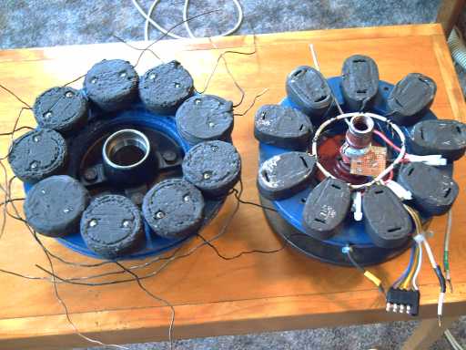
Old (second
version) prototype stator (R) - the one that moved the
car.
"Production
prototype" stator (L): larger diameter, coils with more iron and
more copper, and sturdy standard trailer axle hub.
Fixing Stopped
and Low RPM Currents
After thinking heavier
stuff seemed to be needed all around, I've realized that the problems
I've been having with motor controller burnouts and hot coils in the
prototype can be solved without going to more paralleled MOSFETs and
heavier coil wires. "Magnetic saturation" of iron is one of
those factoids one hears of, but I didn't quickly connect it with the
problem. Now I have:
At very low speeds
such as when the car is just starting moving, the drive signals are
such a low frequency they look like DC instead of AC. Since the coils
are wound for AC, they have far fewer turns of much thicker wire than
they would for DC. (70 turns for 18 VAC versus, eg, 225 turns for 12
VDC.) The high current that starts to flow after perhaps 1/4 of a
second magnetically saturates the iron in the core. Once the iron is
magnetically saturated, the coil starts looking like a short circuit.
That would be when it starts blowing MOSFETs, and also why the coil
wires heat up so much.
In order to overcome
this, the coils need to be pulsed on and off at just a few hertz -
introduced AC - shutting off the current just before the iron
saturates. Since there's virtually no more thrust to be had beyond
saturation anyway, this should provide nearly as much thrust with far
less current and heat. And the bigger iron cores and somewhat heavier
stator of the "production" model motor should provide more
magnetism and thrust than the prototype has before saturating. As
speed increases, this pulse/interrupter circuit phases out and allows
full drive current, per the regular pulse width modulator from the gas
pedal, which will go from 0 to 100% duty cycle.
Hah! forget the #12
wires and quadruple MOSFETs! It's a waste of time, space, copper,
MOSFETs, and electricity!
No doubt others are
cognizant of the problem. Someone who seemed to have considerable
experience told me I'd never get the car to move (the week before it
did), that the motor would sit "stalled" and things would
quickly burn out. He wasn't exactly wrong - I burned out the motor
controller (again) after the successful tests.
And oddly enough,
later on the same day that I figured out the solution and wrote the
above paragraphs (November 5th, which was the day after I recognized
out the nature of the problem), an electronics/green energy friend
visited on his electric bicycle. Evidently, these bicycles are made so
the motor won't turn on until the machine is going 3 Km/Hr. If it came
on when it was stopped, the motor controller might burn out, so you
have to pedal it to start it moving!
But why? After all,
it's programmed not to come on below 3 Km/Hr, so "case: going
very slow" is programmed in anyway. That can't be
it.
The most likely
explanation is that people avoid the problem instead of dealing with
it. On the bicycle, make sure the bike is moving already. On vehicles,
put the electric motor through reducing gears - a lossy transmission -
so it never has to work hard at very low RPM for long before it gets
some speed up.
And I thought I
was slow for it having taken me so long (and so many MOSFETs!) to
realize what the problem was and to figure out a solution. Is this
another "first", along with the "opto-electronic
commutator" "first", both within my direct wheel motor
"first"? I simply can't understand how some of my
"firsts" could be "firsts".
Coils/Electromagnets
With the off-the-shelf
auto and trailer parts, the one "bottleneck", the only
remaining thing that looked like a really time-consuming operation for
making Electric Hubcap motors, was winding the coils.
Asking at motor shops about
having coils wound for me led to the realization that they weren't
going to be able, economically, to provide cores for coils unless they
were ferrite, and even then there would be problems with mounting
holes. Ferrite is used for RF transformers and coils, but for a motor
it isn't as good as iron cores. Pushing a car demands best
performance!
If you use a solid
chunk of iron, the rotor magnets going by will generate electricity
into it - a big "short circuit" block, generating lots of
heat and drag, and ruining efficiency - correctly oriented isolated
strips or (even better) isolated wires of iron are
required.
So having searched for
and asked for a better alternative and not found one, I think the best
idea is to stick with the nail gun finishing nail strips for the
cores, and to vastly improve the production process. If the coils take
1/2 an hour of labour each, they'll be much more economical than if
they take 2 hours.
I still haven't found
a better core material, and a cylinder would be an awkward shape to
cut transformer/motor laminates for anyway. And, the unique coils
could be good merchandise... but that aspect is for the "motor
parts" marketing plan, also in this newsletter.
First I cut a 1/2"
long piece of 2" ABS plumbing pipe since that circle is now the
desired (dare I say it: the IDEAL) core cross section. I assembled the
nail strips into it upright. Then I sprayed them with polyurethane
insulating paint. For the next one, I sprayed one side of the flat
strips first to insulate them well from each other. I put in two 1/4"
nuts at opposite edges and screwed specially cut hex-head bolts into
them, whose smooth shafts extend right to the nuts, where the threads
begin. Short strips of shorter nails fill in the space above the nuts
and around the bolts.
When the coils
including the cores are cast in epoxy or varnished and baked, the
bolts are broken loose with a wrench and unscrewed, leaving the nuts
captive. Holes for bolts will be drilled through the motor stator.
With the nuts, there's now no need to thread holes in the stator
(another minor production speed-up), though the bolts will need to be
just the right length. Nyloc nuts, or lock washers at the bolt heads,
should prevent coil mounting bolts from working loose.
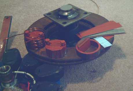
The new 2" diameter coil cores sitting on
the new stator with trailer axle parts, which is propped up by the old
stator.
Then I made a little
jig to wind the coils, and found it works amazingly fast and
well.
Coil winding goes fast with a winder!
Now having a
reasonable way to make the cores and a zippy coil winder, just the
casting is tedious, and no doubt much better procedures - eg, doing
big batches - can be found for that too. So why did I try to buy
coils? Better to sell them! Let's see, 9 coils per motor, 2 motors per
car...
After trying out the
new processes on actual coils, I was dissatisfied. I made a new winder
spool, and now (improving technique) some tape and tie wraps holds the
shape of the wound coils. The core strips are assembled right into the
coils, which are then dipped in motor varnish and baked. This ensures
they fit together well, and it cuts out the steps of spray painting
the core to "glue" it together for handling, and then
inserting it into the coil, which tended to end up scratching the
insulation of the inside coil wires. Using motor varnish instead of
epoxy also makes things easier - you can't mix enough epoxy to simply
dip the coils in as it is expensive and it will all harden. The motor
varnish does require two or three coats and is no doubt not as strong
as epoxy, but unless coils start falling apart in use, it's
enough.
On the old rotor, there was
lots of space between coils, at least 1/2 inch. The new coils pretty
much fill the slightly larger rotor. In fact, I had to make a slightly
smaller winding spool and make a couple of extras in the smaller size,
tossing a couple of the first bigger ones, to fit them all on. I had
to select which one went where, and you can't slip a piece of
cardboard between some of them! (I'll shave a bit off the winding
spool for next time!) Like the magnet rotor when the magnets went from
12 to 18, it now has a more "industrial" look.
When I was making the new
stator coils and cores, I weighed a leftover core (with no coil) of
the old size, and three of the new ones. Theoretically there should
have been 57% more iron in the new ones, but they actually weighed
double: 280+ grams versus 140. This certainly bodes well for increased
thrust! I expect I'm getting better density of nail strips, with the
rows all being straight, where the trapezoidal shape of the originals
left epoxy-filled gaps.
Electric Hubcap Motor Factoids:
* Two small but powerful hubcap motors supplied with 36
volts should have the power to drive a motor vehicle instead of using
the car's engine.
* The motors weigh about 50 pounds each.
* They are very easy to make.
* Most installations are expected to use two motors, or
perhaps four for high performance, even numbers providing for
left-right wheel balance and better, balanced, regenerative
braking.
* Only the car's wheel turns. The only moving part in the
motor is an extended axle that ties the stator firmly to the wheel.
Brackets extending around the wheel from behind prevent the stator
from spinning.
* The virtually frictionless magnetic link to the wheel
magnifies useful power by transmitting it all directly to the wheel.
There's no losses from a transmission or gears. It requires no gear
shifting or other attention by the driver, and it's
quiet.
* Permanent magnet synchronous motors also have the
highest intrinsic efficiency of all electric motor families, further
leveraging the efficient power transfer. Roughly, one might perhaps
expect up to 50% greater range than other (geared induction motor)
electric motor systems from the same energy, and correspondingly
better performance for the same kilowatts of electricity used by the
motor.
* Installation requires no connections with or changes to
the car's existing mechanical components and systems.
* When not in use, the motor has no more effect on the car
than any other 35 pounds of luggage.
* The motor sticks out just 4" from the wheel or a
couple of inches past the fender, less protrusion than the outside
rear view mirror.
* The RPM with 13 inch wheels is about 10 per one
kilometer per hour of speed, that is, 450 RPM at 45 Km/Hour. Most
electric motors prefer much higher speeds, but the "Hubcap"
has good low RPM torque and power. 120 Km/hour is just 1200 RPM, a
stately pace for most electric motors but a good upper range for the
"Hubcap".
* The rotor is a 10 inch steel disk brake disk mounted on
the wheel lug bolts, 6 poles using 6, 12 or 18, .5" x 1" x
2" NIB supermagnets, glued and-or bolted on.
* The stator is a similar 10 inch brake disk (but with
cooling vanes), with 9 epoxy cast coils bolted to it, each of 60 turns
of #14 wire, in 3 phase "Y" configuration. Magnetic flux is
axial.
* A unique design breakthrough is that the stator coil
iron is strips of regular nail gun finishing nails in the coil cores
instead of custom die cut iron laminate sheets. With this and no axle
or other moving parts, the motor is simple enough to make at home, or
the coils could be wound by machine and cast, for super economical
mass production. Individual coils can be easily replaced.
* The motors dissipate their waste heat via air cooling,
avoiding the complexity of liquid cooling systems. There's maximal
coil air exposure and heat sinking with the magnets blowing air in
front of them, an air scoop on the front of the fairing and air guide
vanes, plus a temperature actuated electric fan in case all else is
insufficient at low motor RPMs that don't move much air and high power
(eg, climbing hills and mountains).
Motor Controller Factoids:
* The controller switches the DC power from the battery
onto three power wires that go to the motor's stationary magnet coils,
in a six state drive sequence timed to continually push/pull the
supermagnets on the rotor around in one direction.
* Three optical sensors looking through slots on the rotor
tell the controller the rotor magnet positions, to time the
switching.
* The amount of torque is controlled by pulse width
modulation of the power, proportional to depression of the accelerator
pedal beyond "neutral". Reverse torque to slow the motor
(regenerative braking) is provided by differently timed pulses
proportional to the release of the accelerator pedal above its
"neutral point".
* A reverse switch switches the signals to reverse the
push on the magnets.
* In accelerating, the motor uses energy from the battery.
In decelerating, the motor generates energy, which goes back into the
batteries.
* The individual motors and controllers have minimal
digital logic and will run connected to controls having nothing more
than a 555 timer to generate the PWM signal (connected to the gas
pedal) and a forward/reverse switch, though connection to a
microcontroller "brain" at the front of the car is needed to
provide the more sophisticated features such as dynamic
braking.
* The microcontroller chip in the motor controller is the
"brains" of the switching system, reading also motor
temperature, car speed and direction, and battery
voltage.
Turquoise
Battery Project
November Gory
Details
The battery project
wasn't neglected in November. I'm tackling sealed cases (a much more
challenging aspect to the project than expected) and I've learned some
more electrochemistry.
First, an attempt was
made to make a nickel/zinc battery that wouldn't leak, in a salad
dressing bottle. In the first bottle, shoving the rubber stopper in
hard broke the plastic top of the bottle.
With much trouble and
some ripping of separator papers, the contents were transferred to
another bottle. This one seemed to be charging fine and (at last!) not
leaking. It was late. I went to bed. When I got up in the morning, I
found the bottle had split right down one face and the caustic
electrolyte had leaked all over the table. (Anyway, the transparent
bottle makes a good illustration.) The red color is ferric oxide
powder (yes - rust), smeared on the separator papers to reduce self
discharge. Some of it mixed into the electrolyte.
The basic construction
technique and layout I kept. The next battery was made in a 1.5"
I.D. ABS plumbing pipe. The bottom has an ABS cap glued on, and the
top has an open threaded fitting. The rubber stopper (with the
terminals through it) goes over that, and then the end fitting is
screwed on, covering the edges of the stopper so it can't pop out. The
nickel-brass sheet metal bases for the electrodes, a foot long, are
silver soldered to the #6 wire leads. (also nickel
brass.)
This makes a robust
battery housing and construction that will withstand a lot of gas
pressure. When I tried this out, the pressure certainly manifested
itself, bulging the rubber stopper out to an amazing degree. I can't
bend the stopper a tenth as far by hand! Fearing I may have created a
"pipe bomb", I bled pressure out by forcing a jewellers
screwdriver in - with difficulty - beside one of the terminals.
Charging just brought it back. No wonder I've been unable to make a
battery that didn't leak with any sort of "normal"
constructions! The next one will have a car tire valve on it to test
the pressure and let some out if needed. Perhaps I should be looking
into chemical means to reduce gas pressures in batteries.
I didn't get very good
results with this. When I opened it, I found that the zinc wasn't
wrapped very well and it had leaked out all over.
Then I realized I
could make a transparent battery with pipe of acrylic plastic, using
ABS or PVC fittings, so I obtained the pieces. (Ironically, the only
cap that fit was the one from the dead salad dressing
bottle.)
Acrylic pipe battery starting to
charge.
The ingredients for
this lanthanum-zinc battery were:
* The monel - lanthanum hydroxide
mix, burned to fuse them together in thiamin mononitrate (tinned bean
sauce), mixed with 1-2% anhydrous cobalt chloride in Sunlight dishsoap
(accept no substitutes!), then gelled in agar agar using acetal ester
(made from acetaldehyde made from vodka with potassium chlorochromate
made from potassium dichromate with HCl) for the liquid. (The alcohol
cost more per kilogram than the lanthanum.) On this was sprinkled a
layer of zirconium silicate ("zircon", SiO2:ZrO2). (Phew!
No wonder most people have just stuck with nickel hydroxide! But
this should hopefully have higher energy density and last
longer, if not indefinitely.)
* Calcined zinc oxide
("denzox") bleached with regular bleach (NaClO), with
Sunlight, and 2% cobalt oxide, added. Hard to stir but will gradually
all leak out the tiniest gap... otherwise simple.
* An electrolyte of water with KCl
salt (to s.g. 1.15), some potassium hydroxide, a bit of methyl
hydrate, a bit of MEK, a bit of Methylene chloride, and a little
baking soda. I'm still experimenting with electrolytes. Finding the
right stuff seems to be a key to getting results from "rare
earth" elements in a battery. With one electrolyte mix it charges
the opposite direction from the others!
Gradually growing
bridges between electrodes as it charges.
The bottom popped
off with a bang at 80 degrees C when I tried seeing if anything
special would happen above, eg, 65c where cobalt chloride changes
colour. Evidently ABS cement softens when it's hot! Here are the
electrodes. The lanthanum one shows what should hopefully be some grey
perchlorate mineral, which soon turned a green or cyanish color on
exposure to air. In fact, when completely dry it was a brighter
turquoise colour than nickel hydroxide powder - a sure indicator that
the "Turquoise Battery" project is headed in the brightest
"green energy" direction!
The calcined zinc
oxide electrode didn't look much different than when I wrapped it.
Above that is the other electrode, newly re-wrapped in
cellophane.
As to
electrochemistry... I play with theoretical ideas; I try some
out.
Zinc is generally seen
as the highest energy substance that can be used with an aqueous
electrolyte.
It looks like
dysprosium should make for a higher voltage than lanthanum. I've been
unable to find a figure for lanthanum, but oxidizing dysprosium to
from Dy(OH)3 to
DyO2 in an alkaline environment is
substantially higher voltage than almost any of the other lanthanides.
Again, I can't find the the reactions I'm actually looking for, nor
their voltages:
La(OH)3 + OH- <===>
LaO(OH)2 + H2O +
e- [>1v
?]
Dy(OH)3 + OH- <===>
DyO(OH)2 + H2O +
e- [2v
?]
Note that the
charged/oxidized substance on the right is tetravalent while the one
on the left is trivalent. This is akin to the usual divalent/trivalent
nickel reaction ( Ni(OH)2 <===> NiO(OH), [+0.5v] - in Ni-MH
etc.) but the voltage I expect to see from certain so-called
"rare earths", lanthanum and especially dysprosium, and
hence the energy density, should be higher (all else being
equal).
I can't find a
reference to tetravalent lanthanum, eg LaO2 or LaO(OH)2 in
any tables. In fact a web search comes up almost blank.
However, someone said he had grown crystals of lanthanum oxyhydroxide,
electrically. This indicates that it can be made. He was only
interested in growing crystals, so there was no electrical
info.
The voltage to make
DyO2 is so high it probably
can't be done in aqueous solution, which means it wouldn't occur as an
unintended byproduct. It suggests an excellent battery of around 3+
volts might - possibly - be made with dysprosium-zinc. On the other
hand, I haven't priced or tried dysprosium yet.
Similar
Research
I found a 2005 patent
for a "lanthanide-zinc" battery with many features similar
to what I've been doing with the lanthanum and nickel or zinc. It was
good info and they've done some fine work. (but... the things they'll
give patents for! As it reads, basically any attempt to make a battery
using any element from lanthanum to ytterbium, #57 to 70 violates the
patent. (And the only one they tried was cerium, #58) I somehow
doubt such a sweeping claim to essentially "owning" all
these elements would stand up, but the patent was granted.) I'll
contrast their work with mine in the next paragraphs.
In an alkaline
environment, the zinc is Zn(OH)2 (solid) or Zn(OH)4- - (a dissolved ion) when discharged,
becoming zinc metal upon charging. (This is where, like cadmium only
more so, it can grow crystal "dendrites" that can short out
the battery. I think there are ways to avoid this, and also... one
could perhaps take my batteries with the above layout apart and
slip a sheet of paper or something between the electrodes if it
happened.)
According to the
patent, for lanthanide elements and zinc, an alkaline electrolyte
isn't very good. An organic acid is better, in particular methyl
sulfonic acid. I must comment (a) that getting the organic methyl
group in there should be useful, and (b) that acidity would be good,
even necessary, with cerium, their element of choice, but not
necessarily for most of the other lanthanides.
I myself have wanted
to try di-methyl sulf-oxide (DMSO - compare: "methyl sulfonic
acid"), an organic polar aprotic solvent with unique properties.
In spite of being a simple solvent, it's been classed as a
"drug"... because people have used it topically and claim to
have derived health benefits. It can't be obtained without a doctor's
prescription. If one can get it at all, I hate to imagine the price
per litre sold as a prescription drug instead of as a solvent! I
wonder how much chemical research and processes in Canada are hindered
and thwarted by these sorts of seemingly arbitrary bans and
restrictions on chemicals, that seem to disregard the fact that they
may have valuable uses - perhaps undiscovered uses - besides the one
being considered at the moment?
The same people took
out another patent for a gelled electrolyte using
"carboxymethylcellulose,
a polyacrylic acid, a
poly(acrylonitrile), and a poly(vinylidene fluoride)", again parallel to what I'm doing with
the lanthanum electrode (and admittedly prior). I, however, am
simply using agar agar as the "jello", along with previously
tying the lanthanum hydroxide to the monel powder in the burning
step.
In their acid environment,
the zinc dissolves as Zn++ ion. When the battery is charged, the zinc
is deposited on the "-" electrode as metal. It dissolves
again when discharging. (or apparently all by itself, from what the
patent says. This seems puzzling.)
Also in this
environment, a touch of indium in with the zinc evidently can increase
charging efficiency to up to 95%. Typical batteries are ~~65-80%. Eg, 80% means you have to put
in 125 watt-hours of charge to get 100 watt-hours
out.
It must be admitted
this efficiency is very impressive, and zinc reactions have good
voltage and hence energy. (and I even have some tin-indium
alloy...)
However, the voltage
listed for the acid Zn/Zn++ ion reaction [-0.79v] is notably lower
than for the alkaline reactions [-1.25 & -1.29v]. Yet, they get
over 2.4 volts open circuit voltage, as the cerium ions give
1.7.
One wonders whether
possibly zirconium might not work better for their battery: in acid,
Zr/Zr++++ [-1.55 v], making their battery perhaps 3.2 open circuit
volts with double the amp hours. (and how could "Zirc" not
be a great substitute for "Zinc", when the only difference
is the tail on the "n"?) And perhaps zirconium wouldn't grow
the "dendrite" crystals that have plagued zinc
batteries?
The second of the zinc
alkaline reactions, if it occurs, Zn(OH)4- - + 4e- <==> Zn +
4OH- [-1.29v], is a dissolved ion reaction, so rather similar to the
acid reactions, and it moves four electrons instead of two. Double amp
hours, higher voltage... these are good targets if it can be coerced
into working properly! It probably requires an electrode
separator
that will pass hydroxide ions but not the larger zincate ions. The
patent says they're using Dupont Nafion(r) membrane to pass
hydrogen (H+) ions, AKA protons, and that's some good info, but it
turns out to be very pricey stuff. I'm now trying cellophane, which I
had thought of and bought in the spring and then forgot about. (But
what ions will it pass? OH-? ClO4-? or only H+? or none?)
If possible I'd rather
have electrolytes that aren't strongly corrosive, either alkali or
acid. The nickel-zinc battery seemed to work okay with 10-25% alkali
and the rest KCl salt. (Whether it was as good as straight KOH
I didn't determine.)
For the lanthanum,
I've been trying some organic constituents. Some perchlorate could be
formed oxidizing the salt.
An idea I've been
thinking about is to add some methoxychlor along with or instead of
the MEK. That brings in another methyl group and some perchlorate
forming oxy-chloride in one chemical. Methoxychlor is usually used as
an insecticide. Oh well, I don't think there's many battery
electrolytes one can drink anyway! (Rats: I went to buy some
and evidently methoxychlor has been banned in Canada - one more
chemical I've wanted but am not permitted to buy!)
Having more neutral
chloride and perchlorate for electrolytes is going to create new redox
reactions and voltages rather than the "standard" potentials
listed for alkali and acid electrolytes. I can use the listed
potentials for rough guides, but this is rather striking out on new
ground, and the lanthanum-zinc or dysprosium-zinc reactions and
voltages will have to be found by testing rather than calculated in
advance. I'm hoping for around 3 volts with dysprosium, which has very
high voltages going from valence 3 to 4 in both acid and alkali, and
zinc is known to produce its higher voltage in neutral PH manganese
oxide/zinc 1.5 volt batteries. (The common so-called carbon/zinc
battery.)
So far, my batteries
are showing somewhat lower voltages than expected and poor current
drive capacities, and I must confess I don't have a properly working
product yet. I think I have some good processes and reactions
occurring with some good chemicals (even without the ones I haven't
bought yet or can't get at all). That the things I'm trying aren't
wildly off base is shown by the recent patents by the group of people
working along parallel lines, as mentioned above.
http://www.turquoiseenergy.com
Victoria BC