Turquoise Energy Ltd. News #13
Victoria BC
Craig Carmichael - March 2nd 2009
http://www.TurquoiseEnergy.com
Contents / Highlights:
February in Brief (overview...
summary... the short version!)
INVITATION to Inventors
and Innovative Product Developers
* Owing to the absence of support for
innovative productdevelopment in Canada & BC, we hope
to create a professional innovators' association.
* Exploratory First Meeting Sunday March 15th, 1:30 PM
Electric Hubcap Car Drive Project,
Longwinded Detailed Report
* New motor spins wheel, tests look good.
* But lack of funds eventuates in further delay
of road testing.
Turquoise Battery Project, Longwinded
Detailed Report
* Several electrodes sent to U of Stockholm
for evaluation
Previous Issues Index/Highlights:
http://www.TurquoiseEnergy.com/TENewslettersIndex.html
February in Brief
It's as well I finally
sent the January report without waiting to see if the motor would run.
It didn't. There were assorted problems and it took until the 17th to get
the car wheel (jacked up) to turn. And it still wasn't ready to roll.
Then on the 19th, just as I was satisfied all was in order and it was about
ready for a road test, a corroded battery connection arced, shooting out
bits of molten lead that melted into the battery case, and fried the motor
controller, during a spin-up test with the wheel jacked up.
So I decided to lay out and build a new controller with more room on it
for additional protective components. I'm still waiting for two items to
arrive.
But failure can be the key to progress. The whole experience, of once again
having serious problems partly on account of using old garbage (scrounged
batteries and battery cables) instead of having a bit of money to go out
and buy decent new materials (as any car owner installing one for himself
would), got me thinking.
Just why is it no funding is available
to inventors and innovative product developers? I had been getting together
with two other innovators for Sunday coffees, and I thought, "Why don't
we broaden our circle once a month? We had a monthly product developers'
group in the 1980's. I could run an event notice at VIATeC."
Then the ideas avalanched. Government funding programs seem to operate
in an information and feedback vacuum. What is desperately needed is an
organized professional association of innovative product developers, able
to tell government what is really needed to support real innovation, oversee
the whole process of supporting inventions and innovations that shape a
better future, and perhaps even evaluate and monitor progress of individual
ideas and projects.
This is worth putting some energy into in spite of any additional delays
it may cause to the motor improvement and battery development projects,
and I have other things that need doing that will cause further delay,
such as income tax/SR & ED app, housework and yardwork long put off,
and a long, long overdue update of the Turquoise Energy website. (This
newsletter isn't written in an hour, either, but I think it's worth doing.)
I've hardly been able to look at the projects for a few days now, and it
may be the middle of March before those road tests!
INVITATION to Inventors
and
Innovative Product Developers:
Do we wish to form an Association?
Exploratory Coffee Meeting:
Sunday, March 15th 2009
1:30 PM
at my house, 820 Dunsmuir Road, Victoria
BC,
(inside of 'corner', tall house with hedges,
misc. parking Dunsmuir, Wollaston,
foot of Sea Terrace at Barnard Park.)
RSVP please
Events and conversations
over the last year and more have shown that it's not just me that can't
find funding for developing innovative products. Talking with others who
have made innovative new things, or who would like to have made them, disclosed
that almost none of them could find a penny besides their own resources.
(SR & ED tax credits can help leverage your money and are thus a valuable
tool, but they are not a source, per se, of funds.) Two of those who had
developed new things had their own relatively prosperous companies they
drew funds from, even though the projects weren't closely related to their
businesses.
I have now e-mailed or talked with just a few other
innovators, and we seem to be in substantial agreement about the problems.
I've proposed an organized professional association as a solution and found
they like it, and have some ideas similar to mine. A guide or possible
agenda to focus the meeting is below. All suggestions from attendees will
of course be considered.
If such an association can be organized by inventors from the grassroots,
then perhaps as an organized group we can make recommendations for the
future to the federal and provincial governments of effective means by
which the beginning steps of real innovation ought to be funded.
And there are more detailed ways in which we might as an organized group
become involved in the whole process of resource allocation for projects
that can redefine the future.
Points for debate/Agenda
1. Is the system
working as it is? Do people get a reasonable level of support from existing
programs?
2. Would a professional association of innovators have a reasonable
chance of making our collective voices heard by government? Is forming
an association a good idea?
3. If it is to be a professional organization,
what are the membership qualifications to be? Having invented a product
that became commercial? A technically successful project? Other ideas?
4. Constitution. It would seem inappropriate not to use the best advanced
democratic principles known for such an organization. Having made something
of a study of democratic mechanisms, I have some decided opinions which
we will not be ready to discuss immediately, but are nonetheless sketched
out below for consideration at the appropriate time.
5. It is my impression
that the small funding requirements for many prototyping projects - often
the equivalent of a salary plus expenses - fall beneath the radar screens
of government funding agencies, and also that those programs are much too
rigid to accommodate the beginning stages of inventive development. What
sort of general guidelines might we wish to submit to provincial and federal
government?
6. Would we want to be a body that looks at individual projects
and applicants and passes judgements or makes recommendations about supporting
that project? On what criteria? Possibilities include: * potential value
of the project in the long term* potential immediate benefits of the project*
past project performance record and credibility of the applicant* the applicant's
plans: does he wish to publish his results for all, patent and license,
set up a production line, ...?* prospects for success* valuable lessons
that might be learned (and posted on the web to help guide future developments)
in the event of failure. (In considering the prospects that an inventor
might "strike it rich" off his work, it should be borne in mind (a) that
less than 1% of inventors do, and that (b) unlike a permanent employee,
his funding is only for the duration of product development. If he does
"strike it rich" having developed it, society still paid little for a short
term, and gains much for a long term if not permanently.
7. Would we want
to try to get people with similar projects to work together? Funds might
be better spent and projects completed sooner. The whole is often greater
than the sum of the parts.
8. Would we want to discuss and target specific
areas that ought to be developed? Would we then try to find people with
ideas for developing them?
9. Would we want to help innovators with facilities
and skills they lack? For example, someone might have need of a machine
shop or a welder for a piece, and not have the equipment or skills. Or
someone might need help accessing government for regulatory or other specialized
approvals or support. Where, if anywhere, might we want to go with these?
10. The coffee may well be all gone by this time if not sooner.
Points For Constitution-----------------------
It is doubtless
premature to speak of a constitution, yet I fear if no mention is made
of these important but less familiar specific points of democracy, they
will be lost in the shuffle when the right time does come around.
a) All
votes should be by choice ranking (so-called "STV") as it is the only
voting system where one is completely free to rank the choices in the actual
desired order. If your first choice is eliminated on the first count,
your second choice moves up, and recounting continues until one choice
has over 50%. "Voting strategically", "vote splitting" or the need for
multiple ballots are eliminated. The single "X" voting system has never
worked properly nor served us well when there are more than two choices,
as all our political parties recognize when they select their leaders.
And it can improve debate procedures: There is no need to vote immediately
on each proposed amendment to an idea, as all contested options can be
saved for a single ballot and voted on at the end of the debate after all
has been said, without prejudicing the outcome. Thus: full debate without
interruption, proposal of every option anyone still cares to have on the
ballot, then one vote, and the version most liked by most people is chosen.
b) All positions carrying with them any power of decision within the organization,
including if there eventually come to be paid positions, should be elected
by the membership for specific terms. While day to day decisions may be
needed, we must be careful not to let a clique of permanent staff acquire
more power from the democratic membership than is warranted or necessary.
c) Power to amend the constitution should require no more than about a
55% vote. Over 11 to 9 or so is a credible majority provided all other
processes leading to the vote have been fair and above board.
Many organizations - and countries - hamstring themselves by requiring
up to 75% majorities, so changes are ultra-hard or impossible to make.
75% means that 26 people can hold 74 hostage and prevent action. It makes
revolution a more feasible option for change than democracy! Even 60% means
41 people can prevent 59 from making a change.
And in any organization
where membership is voluntary, dissatisfied people tend to quit, leaving
the minority who like it the way it is behind, so it can be very difficult
to get even a 50% vote for changes that would bring the former members
back.
The Spark for an Association
I'd been gradually
recognizing the almost universal lack of support for innovative development
in Canada over the last three years, but there was a final spark for me
(literally, as it happens), working on the Electric Hubcap:
Just after I finally got the motor running properly on February 19th, a
spark at a bad battery terminal connection blew out the motor controller.
At that point, the unit had been at long last about ready for a road test.
Using new batteries and cables instead of old used, corroded stuff I'd
scrounged would have prevented the problem, and having some spare MOSFETs
on hand would have reduced the delay the failure occasioned. I hadn't ordered
them, hoping to avoid the $80 expense.
It seemed to me crazy that a project to redefine the future of transportation
and to a great extent get us all off of oil quickly, continues to be funded
by one highly skilled but very broke guy living on a few hundred dollars
a month, even after the October prototype drive test [CarMoveWave.AVI]
had proven the concept. The fundamentally better mousetrap is built and
works. It's an incredibly exciting development, full of promise for the
future, but there's still no point applying for funding - all the absurd,
rigid funding rules are the same as if nothing special has happened, and
Canada and BC remain indifferent and detached, unreachable through the
bureaucracies.
I remark again that for the almost trivial amounts of funding these sorts
of innovative prototyping projects can often be done for to be unavailable,
compared with the obvious and almost measureless potential benefits of
successful new designs that redefine the future, shows a warped and unbalanced
sense of proportion and priorities somewhere within our society's resource
allocation processes. Perhaps it would be better to say that the process
seems utterly confused, disordered and dysfunctional.
In my own case, as I have all the skills, tools, equipment and space necessary
to do practically all aspects of the projects myself at home, getting even
a couple of thousand dollars a month would make all the difference. I'm
sure most individuals would agree that would be a true bargain for Canada
or BC, to support the devotions of a skilled, experienced, multi-disciplinary
researcher, inventor and professional product developer with a long history
of successful groundbreaking inventive projects, now attempting - not without
visible and substantial progress - to create the very things most needed
by society in the vital field of energy!
Everyone who hasn't looked for funds for such purposes themselves will
surely be thinking "Surely there are government programs to fund this sort
of thing!"
For this reason, I'll run through them (or is it
"run them through"?):
Regardless of potential benefit to society or to the environment, potential
savings to the taxpayer, prospects of the applicant making any money himself
from a successful project, an applicant's track record of successful projects
or any other considerations, NRC/IRAP (National Research Council/Industrial
Research Assistance Program) and SDTC (Sustainable Development Technology
Canada) paradoxically both ask the applicant himself to put in as much
money as is being applied for or more when he is looking
to them for project funding. As if, in ostensibly helping
to permit him to try to improve the future for everyone, they
were doing him a Favour!
And they won't consider
time and money already spent by the applicant in the equation. (Gosh, thanks!)
Since no one knows in advance how much it will cost or how long it will
take to create something that's never been made before, they are likely
to hope they can do it on their own without going through all the hurdles
and delays these programs impose. Then if they find they need assistance
after all, they don't have the money remaining to qualify themselves for
it.
It is especially ironic for SDTC to ask the applicant for
money: the whole reason the program was set up by the Canadian government
was specifically to fund prototyping because no funds for that purpose
are available elsewhere.
(Perhaps the people allocating the
money should be required to incorporate a company, come up with a detailed
business plan and half their own salary to qualify for receiving the other
half, months later. How soon would there be no one left to submit an application
to?)
BC's "Innovative Clean Energy Fund" specifically prohibits funding
of prototypes, the first material step in innovation. WOW!
Also, none of these programs want to deal with the small (by government
standards) but vital amounts often required for prototyping, again especially
ironic for SDTC since prototyping support is what SDTC was created for.
Only CRA (Revenue Canada) has any useful program: the SR & ED (Scientific
Research and Experimental Development) program will refund a portion of
money already spent on R & D materials (and salaries) at tax time.
This is good leverage for your own money and without the hurdles of the
other programs, but again not a source of funds to live on and work from.
If there are any other available funding programs or sources, they are
certainly well hidden from potential recipients
One begins to see why, in spite of scientific and technical progress, nothing
ever changes in areas too big for one individual to manage, and we still
drive gasoline cars, and there's no economical decent batteries, just the
old lead-acid crap, in Canadian Tire or Wall Mart. Why we head into a new
millennium with energy all around us as wind, waves, tides and sun but
the only proposals that are taken seriously are to flood another valley
of the Peace River and to import more gasoline and natural gas.
Flat little Denmark exports wind powered electricity to Europe when it's
windy. Why has rich, mountainous BC on the ever turbulent Pacific coast
been allowed to become a net electricity importer?
It seems to me there's a hidden organizational vacuum that needs to be
filled, and that organizing it well could pay huge social dividends.
The Electric HubcapTM
Vehicle Drive Motor
February Gory Details
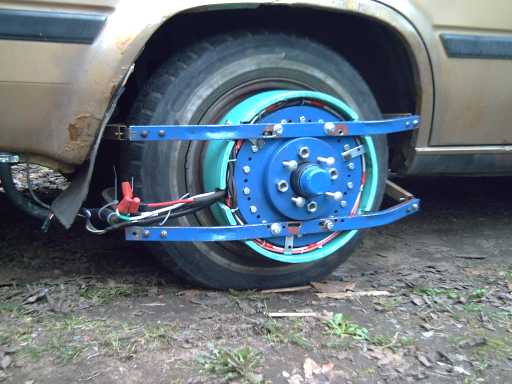
The Production Prototype motor on the car in February.
It seemed to take
an amazing length of time to get the motor running when I thought all was
in readiness.
There were a mistake, more than one omission,
and a bad solder joint that looked fine on the new motor controller interface
board, located one at a time. These things would have been solved faster
if I'd tested everything on the bench before mounting it on the car.
Plus, the mountings of a coil broke and the coil jumped out and stuck to
the magnet rotor. Luckily, the wheel was still jacked up and I happened
to try to turn it by hand and discovered it without further damage. (Driving
the car would have shredded things nicely before I was out of the driveway!)
I spent a couple of days figuring out a better mounting system. Now the
coils would have to almost crumble to come off.
Then I spent a session belatedly sitting down and figuring out where the
slots and optics actually ought to align, instead of just expecting to
adjust them later by rotating something as I had been doing on the first
prototype. It turns out that if the slots and solids are lined up with
the magnet poles, the optical elements should (conveniently) aim directly
from the axle center to the centers of three adjacent coils. So I adjusted
everything to attain this alignment. But that's if the coil
low drives are connected one way at the MOSFET driver chip:
Optics A => A hi &C low
Optics B => B hi & A low
Optics C => C
hi & B low
If they're the other way, A hi & B low, B hi & C low and C hi &
A low, the optics should point directly between the coils, 20 degrees off.
I don't know how, but I managed to wire and rewire this the same way -
wrong - three or four times! The motor ran lazily at 150 or 200 RPM drawing
around 50 amps continuously regardless of speed.
I tried reversing
the motor while it was still turning and 'instantly' blew the phase "A"
MOSFETs. I replaced them, and replaced the socketed IR2130 driver chip
to be on the safe side. The motor ran. So I put the old 2130 back, thinking
it was probably okay and a $10 chip shouldn't be thrown out needlessly.
The instant I touched the power, BANG!, another set of phase "A" MOSFETs
went up in smoke. Now I've burned up 8 MOSFETs instead of four, and the
driver chip. New rule: any MOSFETs go, replace IR2130 regardless of anything.
On the 19th, I rewired the optics to the phase inputs for about the fifth
time and finally got it right.
This time, there was some other
weird problem. Checking things with the oscilloscope revealed that daylight
was activating the phototransistors in the motor! I dismounted the motor,
put the protective cover on it, and put it back on. Problem solved!
The motor ran well. I took it from 12 volts to 24 to 36 and
everything seemed fine, but then there was an arc and some smoke from a
battery terminal. I tightened the connections. It ran fine once more, then
there was another spark from a battery terminal (it shot out some molten
lead, which melted itself into the battery casing) and the motor controller
blew up and caught fire!
It would appear that the cause of
the problem was the bad battery connection and the large transient spikes
inherent in having the main power flash on and off with the motor running,
rather than any fault of the motor controller circuit, which had been (finally!)
working perfectly up to that point.
So! A month working out
the bugs, it ran great for a few wheel spins, and then poof!, it's dead
again. I didn't even get a video!
At that point, the work was stalled because I had to order more MOSFETs.
I had wanted to have some more on hand just in case and to try out a new
layout, but I was reluctant to spend the $80 if I didn't have to.
Oh well, on the bright side the motor runs, setting the timing is figured
out, and the forward/reverse by inverting the photo signals is now tested
and proven to work well. And this time, I left the motor mounted on the
car. Theoretically it should sit there harmlessly, and that has proven
to be the case so far. The magnets induce a slight vibration at very low
speed.
I gave some thought to ways and means to protect the motor controller better
and to limit damage if there's a problem. As it is, if one phase blows
MOSFETs, it seems to damage the motor controller chip, which then manages
to burn out all of them in all three phases. About the only thing that
has never yet blown is the circuit breaker, which should be protecting
all these components at a considerably lower current than their ratings!
I could replace the IR2130 three phase MOS driver with three single phase
IR2110's. Then if one blew, it wouldn't directly affect the other phases.
In addition, I could have a current sensor/limiter circuit shut off the
motor for one or more seconds if an excessive current is seen.
These things add complexity to what seems remarkably simple so far, and
they aren't foolproof. (The IR2110's seem to have no protection against
turning on the high and low sides at the same time, which will require
more chips.)
I made a new controller with the new layout when the MOSFET transistors
arrived.
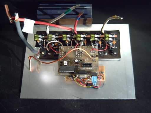
New spread-out "production version"
motor controller layout. (but still with the prototype logic boards.) It's
on the inside of the front cover of the wiring box. The 12 transistors
are mounted on two 1/4" x 1" aluminum bars for immediate heat removal (with
tarpaper electrical insulation). The heat sink "fan" of aluminum roofing
flashing (very top) is a sample of those that will be clamped opposite
the transistors on the outside.
Six fuse legs are soldered to
a solid copper bus bar (+36 volts), with the other leg directly on the
transistor pin. The low side transistors are soldered directly to a heavy
ground bus wire under their legs (rather hidden here). Directly across
each transistor pair are a 100uF & .1uF filter capacitor on the DC
power. The leads that go to the coils are joined by bare #10 copper wires,
each forming an "N" with the #8 output leads soldered at the middle.
What I did do for
better protection was:
1.
Spread out the transistors (as seen) for better heat dissipation and room
to mount more protective components. This layout is what I've been envisioning
for the production model, so I'm just trying it out sooner. For production,
viz: the layout above but with only one long, thin, clean circuit board,
its top edge clamped directly onto the lower aluminum bar directly below
the lower transistors, and the small transistor control wires all connected
at the top edge.
2. I put
individual smaller value automotive fuses in the power line to each transistor.
These should blow long before the breaker would.
3.
I've ordered some 17 volt, 5 watt zenor diodes. The maximum voltage the
MOSFET transistor gates can have WRT the source is +/- 20v, then they fry.
A fried motor controller might send them the whole 36 volts. This may be
why all twelve often burn up instead of just one phase. The zenors from
gate to source should limit the voltage to the range -0.6v to +17v. Normal
operation is 0 v to one battery v, about +14 volts max.
4.
I've also ordered some "MOV's", metal oxide varistors. These interesting
devices do nothing until a certain voltage is reached, their breakdown
voltage. Then the metal oxide conducts until the voltage is reduced, shorting
out the overvoltage. As the voltage selected is above the battery voltage,
the only time they should be active is when there are voltage spikes, eg
when coils switch... or perhaps when there is some bad battery connection.
I've just finished this controller except
for the heatsink fins and the protective parts I don't have yet (at the
time of this newsletter). Other than that, everything is about ready for
further tests when I find the time.
A noteworthy sideline is that in testing the stator coils, I noticed that
energizing a coil with a battery wasn't enough to push a supermagnet away.
It seems that the small-space attraction between the magnet surface and
the coil iron surface overpowers the strong but more diffuse field of the
electromagnet. When I set the supermagnet on a piece of plastic 1/2 inch
above the coil, it jumped away by repulsion when the coil was activated.
This lesson had its effect when the motor was tested on the car. With twelve
volts power, the wheel wouldn't start to turn unless I gave it a start
by hand, and there was a lot of vibration while it was running. I backed
off the stator and rotor from about 0.1" gap to perhaps 0.25" (That's a
guess -- to check the gap was one reason I had wanted to run it with the
cover off!) and then it worked by itself and ran much more smoothly.
Probably accidentally having a large (1/4") gap when I tested the previous
prototype was the reason it worked and drove the car, while a later test
with the gap reduced to 1/8" unexpectedly didn't! Who'd have thought? What
a piece of luck to have made a "mistake" that made the October test successful!
I could well have given up the whole project if it hadn't moved at that
time, none the wiser!
No doubt there's an optimum gap, and
it's a lot wider than I thought it should be. and far wider than for any
other motor type. That's good for efficiency, low vibration, construction
tolerances, and for much reduced stress on the motor shaft inner bearing
and on the coils. (I had noticed the car had a lot of vibration from about
5 to 15 Km/Hr driving with the motor mounted and the small gap. It's vanishingly
less with the larger gap.)
Passenger Heat and Windshield
Defog
I searched on the
web for 36 volt electric fan-heaters. Without heat it'll be pretty cool
in winter and the windshield won't defog if the gas engine is turned off
while driving. I found that they are made: for golf carts, 500 watts. They
appear to be just what I was after, for a couple of hundred dollars.
One morning last week I tried getting ice off the car windshield by putting
an electric fan heater (120 VAC) on the dash, set to 600 watts and low
fan. The ice was thick and really stuck on, and it would have been a tough
scrape (a stiff broom did little). In a couple of minutes or so some had
run down and the rest was melted enough to clear with the windshield wipers.
No doubt if the windshield had been fogged it would have gone about as
fast.
I want to mount the heater so it can pivot in all directions to aim at
any part of the windshield or backwards towards the driver and passenger.
Two heaters might be good for starting up, but if left on they'll certainly
shorten the driving range. (Good batteries with very long cycle life...
must get those going!)
Battery Voltages: 36 Volts
Rocks!
Also for 36 volt golf
carts were battery state-of-charge meters for lead-acid batteries, which
may or may not be useful once I get some new chem batteries going, but
are inexpensive and will be valuable until then.
In the search, I ran across a golf cart maker's interview. It's from 2002
but it has some interesting material.
http://www.golfcarcatalog.com/index.cfm?fuseaction=archive&step=3&archive_id=16
"Craig Journey was the lead electrical engineer with E-Z-GO, starting in
the early 1990Õs, and a pioneer in the development of Electronic
Speed Controllers for Separately Excited Field DC Motors."
Among many things, Journey said:
"Anything over 36 volts, you have to be warned and marked. In a 48 volt
system there are additional issues, but there is no doubt in my mind that
72 volts is a hazard. The National Electric Code now has two numbers, 30
volts wet and 60 volts dry."
I'm so glad I switched the Electric Hubcap from 120 volts to 36! Functionally,
the only differences besides safety are the increased diameter of a few
short heavy wires and the specific specs of a few power components, and
you can't plug in house lightbulbs. (I wonder what he thinks of 144 volt
and 300 volt cars? I hear police and rescue workers aren't permitted to
touch badly damaged hybrid cars even if someone inside needs help.)
"As a matter of fact the hazard above 48 volts is not an electrocution
phenomena. The phenomena that kills you is called 'let go'. In other words
you'll touch one of these high potential sources and you'll lose control
of your voluntary muscles and can't let go. So it doesn't electrocute you.
You can't breathe so you suffocate. It takes 7 or 8 minutes to die."
DC is worse than AC because AC goes on and off giving some chance (though
sometimes not), while DC is continuous.
And finally, in case I thought I was having a rough time with the motor
controller, which has a much more demanding job than the golf cart field
winding controllers, he notes: "There
are some failure modes associated with all these electronic systems and
it took us a couple of years to figure them out."
In one year I've done the whole Electric Hubcap motor design and prototyping
all by myself from the ground up: mechanical, electrical and electronics,
including the motor controller as one of its components. (There have been
at least three versions of most everything.) Of course, there will always
be more electronic "failure modes" waiting to be discovered!
Electric Hubcap Motor Factoids: [Deleting-- see "About Electric Hubcap" page]
Turquoise Battery Project
February Gory Details
Electrodes Sent for Evaluation
I made contact with
an alkaline battery researcher in Sweden. He offered to test a few of my
electrodes, so I sent him two variations of nickel, two of zinc, and titanium,
calcium and antimony ones, 7 in all. All of them have a couple of percent
cobalt added to ensure conductivity, and all have a layer of zirconium
silicate dielectric "shield" sprinkled on top (and around the edges) to
hold metal ions in place and prevent dendrite growth at the separator sheet.
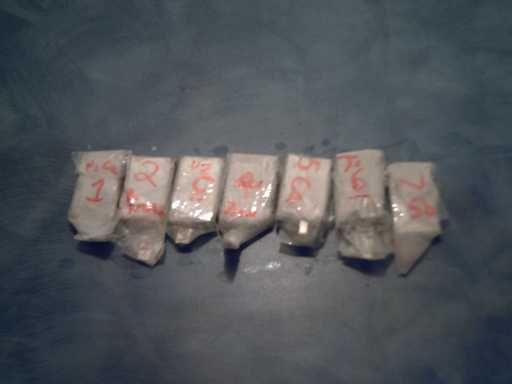
Seven electrodes that took a surprising amount of time to make
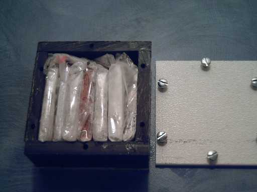
The electrodes carefully boxed.
The nickel hydroxide
with 15% potassium permanganate electrode looks almost black, which colour
holds great promise for being highly conductive - very high amps for a
given size. The other nickel one (below) has a thin layer of calcium at
the collector plate, promising to prevent or reduce outgassing during charging,
which builds up pressure inside the battery until (in my experience) the
case wants to burst.
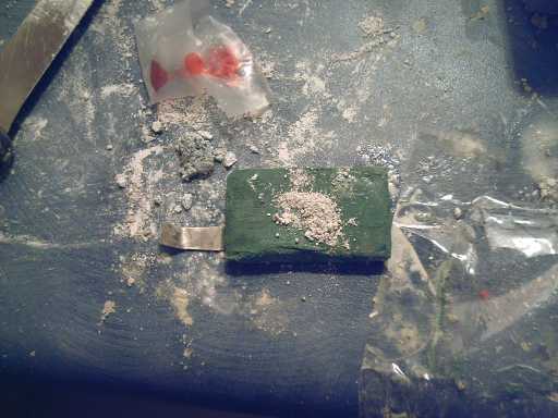
The true green battery chemical: nickel hydroxide.
Collector plates (with tabs) are "nickel-silver" (copper, zinc &
nickel alloy 65%,18%,17%) with a 60 mesh stainless steel screen on top
to help connect the chemicals to the plate. Some of the zircon is sprinkled
on top.
The calcined zinc
oxide ones are one plain and one with 1% antimony oxide, hoping again to
stop or reduce outgassing.
The other three electrodes are more
speculative. The antimony oxyhydroxide one (+ 0.8v?) may not be solid on
both sides of its (uncertain) redox reaction in alkali solution. (I have
better hopes for it in neutral electrolyte.) The titanium oxide
one (- 1.38v) will have less amp-hours per weight than zinc, but may (or
may not) be more conductive. (Again, it may do better for amp-hours in
a neutral electrolyte.)
The calcium one (+ 1.55v) looks promising,
but one never knows for sure what will actually happen. Also the density
is low... similar to nickel hydroxide. Though
having little time to spare, I did put together one sealed cell of nickel
and zinc, in mildly acidic electrolyte of mainly KCl with CH2Cl2, and HClO4
(AKA potassium chloride, methylene chloride and perchloric acid). This
is the first one since discovering the need to compress the powders. The
nickel has potassium permanganate, but I diluted it to 7.5% instead of
15%. It still looks virtually black.
It charged but very very
slowly. Somehow, I'm still not getting those ions going easily through
the cellophane. This appears to be the main stumbling block right now.
How is it others are using it and similar semi-permiable products and getting
good results? Evidently I need to do more reading and maybe experimenting.
While admittedly trying to stress the nickel with potassium permanganate
electrode as little as possible, in removing and reinserting it from the
battery my impression was that it seems like a little rubber hockey puck,
and it didn't break or crumble. This surely bodes well for a long lasting
electrode that will take many cycles.
I decided to try magnesium perchlorate as an electrolyte. So I looked out
on the web for how to make it and found that the chief reason to want to
make it at all is that it's considered to be a good neutral PH battery
electrolyte, both aqueous and non-aqueous for lithium! This
was also my first clue that I was on the right track with perchlorate.
I had I bought some potassium perchlorate, along with perchloric acid.
But it turns out that although KCl is quite soluble, KClO4
isn't. Sodium, for NaClO4, is more soluble but would
probably have less conductance, so the magnesium (MgClO4)
appears to be a good choice.
I'll make some MgClO4
(mix MgCO3 with the right amount of perchloric acid.)
Then I'll open the battery and put some in, and try some other separator
sheet.
I'm hoping for some interesting results. First, perchlorate and permanganate
are such strong oxidizers that the nickel, or a good portion of it, may
charge from Ni(OH)2 (valence II) to NiO2
(IV) instead of just NiOOH (III), thus moving up to twice as many electrons
for double the amp-hours. Second, the voltages will be different in neutral
solution. The nickel may be +0.75 to as much as +1 volts instead of +0.5
volts, while the zinc will be reduced from -1.28 volts reaction to perhaps
-1 volts.
Thus we may see the nickel providing two, three or
even four times the energy it does in alkali, the zinc losing almost 30%,
and a cell voltage not too far under two volts. The improvements to the
nickel make it look like a much more attractive cathode than it is as usually
used in alkali! Altogether it should make for a battery around half the
size for a given energy, and the permanganate in the nickel should increase
the available current per square centimeter of interface considerably.
At least, those are my expectations, without having tried it yet. IF I
manage to solve the separator sheet mystery.
I will of course try out other electrode elements as indicated last month,
but zinc is good if the zirconium keeps the dendrites under control, and
the nickel looks much better than it was. It will be ironic if after having
looked at so many possible electrode elements I end up using "the usual",
nickel and zinc! However, I think my supporting ingredients should make
them better.
NEW!
Liquid Battery
MIT Review shows a
new battery conceived by Donald Sadoway with
liquid metal electrodes and liquid salt electrolyte. It would have to be
heated substantially to melt the metals, but it looks very interesting!
It's intended to be huge and for storing tremendous amounts of electricity,
like solar power during the day for cities at night. WOW!
In
the article, the bottom of the three layers is said to be antimony (a dense
cathode element as I mentioned last month). The electrolyte, the middle
layer, is a liquid salt that's lighter than antimony, The top layer is
magnesium, lighter than the salt. The metal top and bottom of the can are
the electrode terminals.
Sadoway did however say he'd switched
materials and declined to say what metals he's now using. What salt(s)
were used weren't mentioned at all.
 As the full battery (right)
discharges, the metals are oxidized or reduced and become magnesium antimonide
dissolved in the electrolyte (left). Recharging restores them to their
liquid metallic state, and they rise or fall to their place in the gravitational
scheme.
As the full battery (right)
discharges, the metals are oxidized or reduced and become magnesium antimonide
dissolved in the electrolyte (left). Recharging restores them to their
liquid metallic state, and they rise or fall to their place in the gravitational
scheme.
My guess is with Sb & Mg it might be around 3.5
to 4 volts (not mentioned), and the article says it has tremendous (but
unspecified) current capabilities.
I'm not sure if I could
make any use of this fine looking idea for car batteries or not. It certainly
looks like a major departure from what I'm doing now! (Let's see... what
metals and salts are liquid at about room temperatures? mercury (ugh!),
gallium for metals, hmm, what salts might be liquid?...) Say! the
bottom metal (heaviest) could be a solid, the other layers floating on
it! The top metal (lightest) could also be a solid if it was free to float
up and down. That could solve many problems for a moving car and greatly
expand the range of possible elements. Hmm!
How about a cylinder
with a metal bottom (+), metal cap (-), and flexible rubber or accordion
fold sides? Hmm, Hmm!
I can also see some potential problems
with using solids in this application, but it bears more thought.
http://www.TurquoiseEnergy.com
Victoria BC