I uploaded all the previous newsletters to the Turquoise Energy Ltd. website, and worked on the preliminary construction/installation manuals for the "production" model Electric Hubcaptm (EH) motor and uploaded it. These tasks were a major occupation for the month.
When motor and appliance manufacturers discover on-line my "opto-electronic commutator", it will facilitate adoption of more efficient and flexible PMSM motors (including my axial flux motor designs) in place of induction motors, in everything from washing machines (especially!) and refigerators to shop tools and industrial equipment. Here is a "spin-off" benefit of my R & D work to the progress of civilization! As is typical of such novel designs, it's not practical under existing rules for the inventor to attempt to gain any reward from it.
Someone pointed me to another direct-drive PMSM car wheel motor. E-Traction's "TheWheel" makes many of the same claims as my EH claims, but estimates 50% energy reduction where I've more conservatively been saying 33%. The EH should actually have an edge in efficiency, and their motor, as designed and configured, can't be used to retrofit existing cars.
I picked away at the actual motor project, generally for an hour or two or three most days amongst many other things. Weather (rain, snow, and continuing icy temperatures to March 33rd) and other commitments got in the way. Various minor problems were gradually identified and overcome. (Some were unseen & unsuspected "leftovers" from February's battery spark problem.)
By the 26th everything seemed to work, but the motor had little power. It spun better in reverse than forward. It moved the car slowly on level pavement, and nothing blew up (a tremendous plus!), but obviously there's still a problem. Judgeing by the high currents, the timing must be off... somehow. (I thought I had the timing all worked out!)
On the 28th I finally(!) found a nice "wok cover" end cap for the motor with its protruding trailer axle.
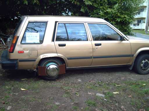
The "dressed up" motor on the ever elegant '84 Tercel wagon.
The sign, "Do you want to hybridize your car?", is really there as much to answer the inevitable question "What is it?" as to attract workshop participants.
The 31st saw the motor removed again to install a "ligature" clamp (clarinet players will be familiar...) so the optics board can be rotated to find the timing angle for optimum performance. Sigh, another month and I'm still not driving electrically!
Competition ?!?
Here's a direct drive PMSM wheel motor design from Holland, that's electro-magnetically very similar to mine. But while this design is reversed with the rotor and magnets at the outer rim, it still uses radial flux design and so their motors will be heavier (and it's unsprung weight), more complex and expensive, and too fat for the outside of a car wheel.

E-Traction direct drive wheel motor for hybrid busses - They're getting very close!
A news report on it: http://mobile.technologyreview.com/energy/22328/page1/
The company: http://www.e-traction.nl/
As they are also using a PMSM motor of large diameter, they make some essential claims very similar to the EH:
| E-Traction TheWheeltm Claims: (quotes clipped from website) |
Turquoise Energy Electric Hubcaptm Claims: (roughly as previously stated) |
| "more than 90% energy efficiency" | probably over 90% efficiency. (...and doubtless a bit higher than TheWheel's. [improved coils]) |
| "delivers up to 15,000 Nm" | High torque at any speed from 0 up |
| "direct drive traction at the only place where it matters, .....at the wheel" | Direct drive efficiency: no gears, no transmission; the car wheel IS the rotor of the motor. (same meaning) |
| "The greater the diameter of the motor within the wheel, the greater the torque." | The axial flux Electric Hubcap's effective diameter is
much greater than a typical radial flux motor, providing much more
leverage of the magnetic forces, for much more torque. (same meaning) |
| Liquid Cooled | Good air flow cooling eliminates the need for a liquid cooling system with its added complexities and weight. |
"On average TheWheel™ uses only half the electric energy of a typical geared traction motor." |
<>Average of 50% better performance than a typical geared electric vehicle drive. (Ie, uses only 2/3 the energy.) (same meaning; differing estimate) |
Since the drive efficiency of EH should be marginally better than E-Traction's, if their bottom line estimate is accurate, evidently my estimates of the savings have been erring substantially on the conservative side.

This is probably one good reason for going "open source": putting all the tech info onto the web so anyone can make and install them. The Electric Hubcap will beat them into the open market, or at least the north American market. Then Turquoise Energy Ltd. with minimal financing can start to produce complete car hybridizing kits plus key motor & controller making parts for small garages and home workshops, with a big headstart on anyone else, for a rapidly self-expanding market that will soon become high volume. I'm sure a kit for $1500 to hybridize an existing car (excluding batteries, of course) is doable and would be a big hit! Getting the price down to $999 would be gravy.
According to the specs shown, the one electrically most similar to EH is their SM350/1, which doesn't mount on a wheel:
Power: 6.0 KW (versus 3.6 - 4 KW)
Amps - nominal: 150 (versus 100 - 110)
Amps - peak: 300 (versus (?)150)
Torque: 150-200 Nm, 600 Nm peak (versus ?)
Weight: 85 Kg (versus 22 Kg)
Diameter: 378mm (vs 330mm)
Length: 275mm (~80mm+)
Four notable specs are the power - theirs has more; the peak amps - the EH protection circuit seems to have it under better control; the weight (85Kg unsprung!); and the width - theirs is almost 11 inches!
I haven't been able, without equipment, to measure the torque of the EH. In my one attempt with a 25 pound fish weigh scale at 6" radius, the scale hanger immediately broke, the pieces flying off with force - and IIRC that was with 12 or 24 volts, not the full 36.)
They are developing or have a new model specifically for cars, the SM450. Torque is claimed as 400 Nm on one page and 1200 Nm on another. It's not shown on their specs chart with the others. Wheel diameter is 450mm (~18"), necessitating a thin wall "low profile" tire.
They may get the weight down to where it's usable on a wheel made specifically for it, but they aren't going to get the sort of weight that can make it into a low-cost add-on for an existing car, which is where the high-volume business opportunity lies.
Although there are many similarities, they are going to have to considerably alter their designs if they are going to compete with the Electric Hubcap, but it would certainly appear they have the resources and the know-how to do so if they wish once they've seen the Turquoise Energy website & the Electric Hubcap designs.
The Electric
HubcapTM Vehicle Drive Motor
March Gory
Details
On March third I thought the controller was ready to put in the car save for drilling some holes for screws to attach it. That night I had a dream where I was checking out the motor controller. A voice said "It's only prudent to test the pins" - nothing vivid, just a few seconds. Okay, then... ready except for screw holes and testing the transistor pins!
On the fifth I got to it again, and put the ohmmeter on it. I had decided to remove the wires (some rather crispy) from the bottom of the circuit board to the transistors, and solder new ones on the top side. I couldn't see the circuit traces, mostly running on the now hidden bottom of the mounted board. There was a short circuit and two identical wrong connections, any of which would have kept the board from working and possibly fried it in short order!
Of course, that board was made with a completely different layout in mind and is now rather chaotic. The production board layout (that I have yet to tackle) will be set up with the connection points all in an orderly row along the top edge.
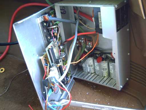
New aluminum wiring box with controller spread across the lid. Not quite visible here are the "fan" heat sink fins of aluminum roofing flashing clamped on the outside of the cover behind the big transistors.
On the 20th, I finally got up the courage to try 36 volts. A couple of MOSFETs and their fuses blew. On the 21st, after fixing (yet another) problem on the circuit board (probably created by the February burnout), I spun it with 36 volts and it seemed fine.
But when I disconnected the test controls and hooked up the real operator controls at the front of the car, things started going wrong again. The motor took off like a banshee without touching the gas pedal, as soon as I clicked the switch on. The low-speed protection circuit wasn't limiting the current, and It blew all the fuses. Not yet aware just what was happening, I put in bigger fuses, 40 A instead of 30 A (80 A per phase instead of 60 A). Two of those blew almost the moment I flipped it on.
I must say, I'd become almost terrified to run tests lest I again end with a controller on fire and all the main driver parts blown. Blown fuses instead is a vast improvement, a hidden advantage of having a protection circuit that limits normal current to under their ratings even at startup!
Finally I measured the resistance of the gas pedal potentiometer. Open circuit! I found a bad solder connection on the wire at the plug and fixed it. STILL open!
But even as I checked it out I realized that a control defaulting to "over max" instead of "off" with any typical problem was not a positive design feature. The circuit will have to be changed.
Connector Evolution
On the sixth all was
ready and I started to install the controller. As usual I had a hard
time trying to get the marette connectors onto the three sets of three
heavy #8 wires. It was a continuing headache: I remembered spending 25
minutes one time making these three simple triple
connections.
Surprisingly, such terminal blocks as exist (besides telephone wire blocks) seem to only tie two smaller wires together, not three and not heavy ones. I guess electricians usually have lots of room and wire length for the marettes, which do after all make good connections.
But enough was enough! I made a wooden connector block with three 1/4" bolts sticking out to hold the wires. This necessitated soldering lugs on the wires (and buying them).
Somehow that seemed to use up the whole afternoon.
That sunny afternoon was followed about 10 days of rain and snow! ...in Victoria ...in March!
In the paper on April first was something about a "Pacific Decadal Oscillation" (PDO) bringing cold weather to the west coast. It must have been an "April fools" article... it doesn't explain the cold temperatures elsewhere and no mention was made of the fact that the last 10.7 year sunspot cycle was (IIRC) over 12 years long, the weakest on record, which will naturally bring a decade of cold, wet weather (worldwide), after the strong cycle that brought the warm 1990's. Shortest (strongest) cycle since they've been recorded brought the 1930's "dust bowl" years.
Someone said one day in early March that it was -45 (!) in Edmonton. I grew up in Edmonton and it was Never that cold! About -30 (F), in December or January, is the worst I can remember! Even in absolute temperature terms, 228 degrees K (-45 C) is scarcely 3/4 the thermal energy of a balmy summer day (300K). But I digress.
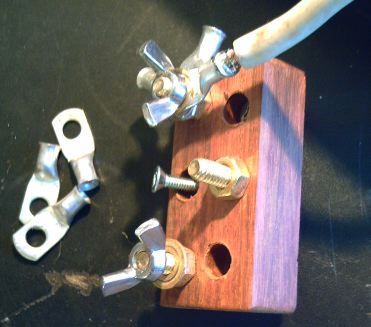
Wire Connector Block #1 in fine Cambodian rosewood,
with terminal bolts protruding
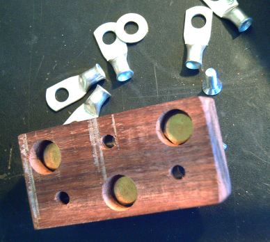
Underside of block, showing recesses to prevent bolts touching chassis
After I installed it, it looked like the lugs could potentially twist around
and short between the posts. I could work around that, but I decided
it just wasn't a very good arrangement for a final
product.
What I had really wanted all along was something like the screw-down strips found in circuit breaker boxes for the neutral and ground wires. So I decided I would just have to make something like those.
I bought a 3/4" square rod of copper.
As I walked in my front door with it, I had a sudden flash of a much easier to make connector block that didn't need the solid copper piece at all! But since I'd just bought it, and since it seemed like a very good design, I decided to persist.
At the end I drilled a left and right side hole right through it, big enough to insert #8 wires. Then I cut it to 1/2" long with an angle grinder. Into this "cube" I drilled and threaded smaller holes for "machine screws" (AKA small bolts) to clamp the wires down with, and a center hole for a mounting bolt.
Off the wires came the lugs, so soon after soldering them on! (That's product development - the instruction book has yet to be written; "standard practice" has yet to be worked out!
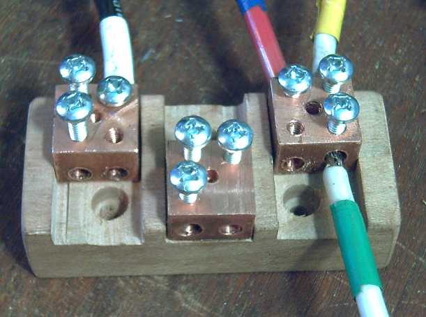
Second version connector block, in Pacific Dogwood. This is the one I used.
(The same mounting bolt pattern as the previous block was retained, so I didn't have to un-mount the wiring box and make more holes.)
But, having thought of another and simpler way of doing the same thing, I just had to try it out! This idea used short sections (1") of small "1/8 inch" (actually larger) threaded brass plumbing pipes. These have a thick wall... evidently for threading a bolt into! Making an unfinished sample (one pipe) took less than an hour. The pipe was big enough to stick in a #6 wire, or two #8's. One set of threads stripped when I tried to do up the bolt. I turned the pipe over and drilled 2 slightly smaller holes in the other side. It was tougher threading them, but the result seemed more solid - at least, I did them up pretty tight and they didn't strip.
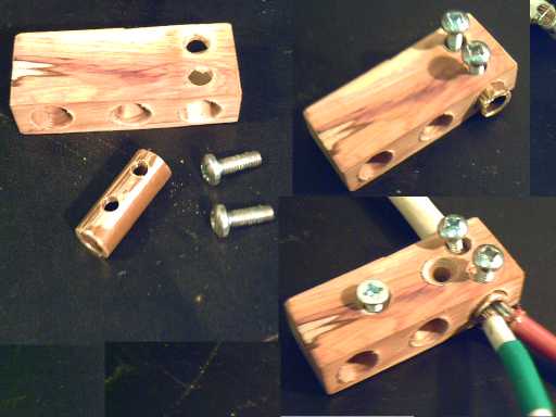
Third version connector block, in hard, gorgeous Lilac wood.
The wire clamp bolts hold the brass pipe in place with no extra mounting bolt.
The pipe can rattle around just a bit.
I note that the inside
of the pipe was a bit corroded, whereas since I'd just drilled it, the
holes in the copper cubes were clean and shiny. Probably the brass
pipe should be cleaned inside before use, which (unless you can think
of an easier way to do it than filing it) probably negates some of the labor
saving.
So that was four evolving versions of connector terminals counting the original unsatisfactory marettes. The copper cubes is doubtless the best and most reliable version.
I suppose I should rejoice that some sort of custom terminal block like that will doubtless be one of the products Turquoise Energy will supply to people who want to make and install their own motors.
I also think a heavy cable "slim-line" in-line plug and socket at the wheel to replace the marettes for the motor is in order. (There isn't room for the bulk of a regular type stove plug and socket, unless they stick out from the side of the car.)
Inductive Phase Lag
One day I thought of a new aspect of motor operation I hadn't previously
considered, and feared it might be significant. Up to that point,
I'd been thinking "This is great, this optical system provides
ideal timing for the coil drives, both forward and
reverse!"
But the current in an inductor, and hence the magnetism, would lag behind that "perfectly timed" applied voltage. Was the lag trivial, or was it enough that the timing depended substantially on the RPM? Did it need something like a centrifugal timing advance?
The more I thought about this, the more concerned I became. After all, I've had to rework virtually every aspect of the motor at least twice since I started owing to failure to take various things into account. I keep finding ignorance isn't usually bliss when designing something! I finally decided I should check the inductance of the coils so I could work out the phase lag. (Oh no! - math and formulas, argh!)
I traded a couple of supermagnets to someone who wanted them for the use of his super-duper multimeter that measured inductance, capacitance and transistor beta along with the more common functions. One lone coil read 0.60mH. (Later another meter verified the reading, showing 0.58mH.) I had thought it would be way higher, but what do I know? Any two phase wires of the assembled motor stator also read 0.60mH, the same to two decimal places, a seemingly odd co-incidence as any phase has two sets in series of three coils in parallel. If they were 6½ resistors, we'd expect 4½, but coils in proximity, ie all packed onto the same rotor, interact magnetically to increase the inductance, and evidently the result happened to be identical to one lone coil. (Other loops of wire and the other stators gave quite different and commensurate readings.)
Given the inductance figure, we can derive the rest.
A = V*S/H.
where A = amps, H = henries, V = volts, and S = seconds
First we want the time lag, seconds, to "full" current at maximum drive, so:
S = A*H/V
S = 90 * .00060 / 36 = 1.5 mSec
Then we want the angle the wheel rotates in 1.5 milliseconds at maximum speed. We'll call maximum speed 130 Km/Hour. The fastest that will typically be is with a smaller 13 inch wheel, 1300 RPM. 1300 R/Min = 21.67 R/Sec. In each rotation there are three electrical cycles, one every 120¼, so 65 cycles/Sec or 0.01538 seconds/cycle.