April was a busy month. I may have acquired a business partner. Nothing is on paper, but he has considerable administrative experience, seems very enthusiastic and is bringing out novel ideas for organizing a considerable enterprise around the motor kits with much local involvement, much the same way I've been churning out and developing technical ideas.
We sat down together and typed up an on-line application for a "New Ventures BC" award for the motor. This year there are six cash awards of $20,000 to $119,000, funded by the BC Innovation Council and other notable sources. I now have to write a short business plan for the next step. (I should be able to get some good material from past newsletter articles!)
Also the subject of much typing was the preliminary manual for making the motor controllers, posted to the web about the end of the month. This is actually a "generic" controller for any variable speed PMSM that's fitted with my "optical commutator", inside the motor or on the external shaft, and as it's much the simplest PMSM controller circuit posted to the web, a lot of people are likely to use it or adapt it to their needs.
Naturally I concentrated mainly on the motor. It seemed to be running well, but try as I might to tweak the performance, it just didn't seem to have enough "oompf". In fact, with the low speed protection circuit, it had less low speed force than the smaller first prototype that moved the car in October. So: great motor, cheap and easy to produce and an advance on the state of the art, but evidently one this size won't properly drive a car by turning one wheel directly. (All those who were sure that would be the case can now point your fingers and laugh.)
But, better than upsizing, driving two or all four wheels, or gearing the motor down... what about a torque converter?
On an automatic transmission car, the drive shaft can be stopped or turning more slowly than the engine. They're heavy, bulky, oily and inefficient, but engine torque can be magnified as much as five to one under heavy load, decreasing to near unity as the load lightens.
For electromagnetic reasons, it's quite hard to move a piece of metal, even non-magnetic metal, across a supermagnet quickly. It's like it was going though molasses. A magnet rotor turned by the motor, facing a "free spinning" aluminum rotor on the wheel, would drag it around. It seems to me it should be possible to make a marvellous compact, light, magnetic torque converter!
I think that would enable the single wheel motor to run a car, essentially the original plan with an additional required element.
Of course (sure enough) there's no way car hybridizing workshops can start in May, or even June. If anybody wants to make a motor(s) for purposes that don't need the torque converter, please give me a call - perhaps we can arrange something.
The Electric
HubcapTM Vehicle Drive Motor
April In
Detail
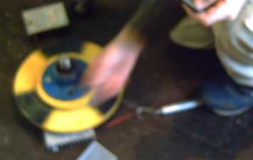
Timing Adjustment Experiment
I made a way to
adjust the timing of the motor signals and tried it out. It ended up
with the timing about where I'd originally determined it should be, the
optics in line with the centers of the coils. Also, it wasn't very
critical, which means (given last month's calculations) that current
phase lag won't make any notable difference at any likely current or
speed.
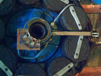
The "handle" (soon changed to plastic) allowed rotating the optics board with the motor running.
It appears to be an unnecessary refinement.
Thin-line Power Plug and Socket
I had
been connecting the motor to the cable from the car with marette
connectors. I would have liked to use a dryer or stove plug and socket,
but they're too bulky to fit in near the wheel, unless they stick out
from the side of the car.
Inspired by last month's success with the terminal blocks in the wiring box, I took some copper bar for pins, brass rectangular tubing for sockets, and some acrylic plastic for the bodies and made a "thin line" plug and socket only 1/2 inch wide. An aluminum side on the socket bolts it onto the mounting brackets coming from behind the wheel, while protecting it from gravel.
Inspired by last month's success with the terminal blocks in the wiring box, I took some copper bar for pins, brass rectangular tubing for sockets, and some acrylic plastic for the bodies and made a "thin line" plug and socket only 1/2 inch wide. An aluminum side on the socket bolts it onto the mounting brackets coming from behind the wheel, while protecting it from gravel.
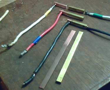
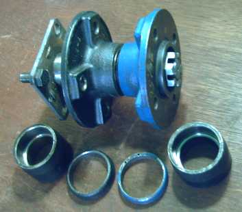
Plug & socket connection elements: Copper bar for pins (Smith Bros.), brass rectangular tube for sockets (K & S Brass - hobby shop). Hammered them to shape until they fit, very snugly.
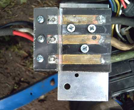
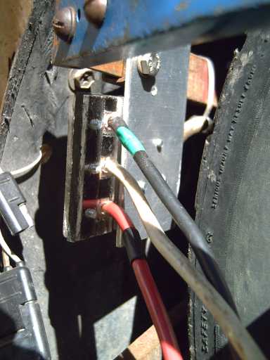
The "thin line" plug & socket for the motor power wires. One side of the plastic is screwed rather than glued: the pins have to be soldered to the wires before assembling into the plastic bodies.
I did two videos of making these, but I'm not sure I want to pursue that line of instructing.
(The second image may give the impression that the mounting bracket and the cable touch the tire treads, but they certainly don't.)
Magnetic Torque Converter: Torque Leverage Without Gears
The torque from the motor wasn't looking very promising, but on about
the 18th I realized there was another way to connect a motor besides
direct drive or gears: with a torque converter. Automotive torque
converters are heavy, bulky, oily and not very efficient -- but they magnify torque, and make automatic transmissions possible.
Now it's quite hard to move a piece of metal, even non-magnetic metal, across a supermagnet quickly. Moving metal through a magnetic field induces (generates) current in that metal. If the metal is a coil of insulated wire, the basis of an electric generator is found. With a solid chunk of metal, however, the current flows around inside the metal as a short circuit, creating a counter magnetic field. The force moving the metal is resisted by the counter field. That's how "instant stop" lawnmowers and so on work: turning them off shorts the motor leads together (the power switch is specially made), which generates electricity into that short. The rapidity of the stop illustrates how much torque can be exerted.
Now it's quite hard to move a piece of metal, even non-magnetic metal, across a supermagnet quickly. Moving metal through a magnetic field induces (generates) current in that metal. If the metal is a coil of insulated wire, the basis of an electric generator is found. With a solid chunk of metal, however, the current flows around inside the metal as a short circuit, creating a counter magnetic field. The force moving the metal is resisted by the counter field. That's how "instant stop" lawnmowers and so on work: turning them off shorts the motor leads together (the power switch is specially made), which generates electricity into that short. The rapidity of the stop illustrates how much torque can be exerted.
A magnet rotor turned
by the motor, magnetically coupled to a "free spinning" aluminum rotor on the wheel (a rotor or cylinder or both - radial or axial flux or both),
would very strongly drag the wheel around. Using both arms and all my
strength, I could only turn a 10" magnet rotor sitting on a 3/16"
thick aluminum plate about 2/3 of a turn in one second: about 40 RPM. A
motor turning 400 RPM would exert ten times the force I was able to.
The aluminum rotor would "pick up" the force of the motor somewhat
similarly to the output turbine of a torque converter. Surely it should
be possible thus to make a fabulous compact,
light, high efficiency magnetic torque converter!
A quick search, surprisingly, revealed no evidence on the web that any such idea has been or is being utilized. A casual experiment on the 22nd disclosed that the force exerted seems, as expected, to vary linearly with speed.
As the rotor is rotated (clockwise), the aluminum heatsink (its top face about 1/8" below the magnets on the rotor) tries to fly off to the left, pulling on the fish scale held by the foot. The faster the rotor is turned, the more pounds read on the scale. A small clock (bottom edge of image) audibly ticks off seconds to help estimate rotor speed.
MagnetDragDemo.AVI movie.
We know the motor barely moves the car starting at 0 RPM, but with the torque converter, it might push the car wheel with that same force when it's turning at, eg, 50 RPM, and so it would have double the force at 100 RPM or triple at 150. As it speeds up, the motor is more able to supply whatever force is required of it. Somewhere in there, the car should start moving, even up a steep hill. If the motor can't attain the speeds needed to move the car well, the torque converter's magnetic coupling is adjusted (reduced) so the motor has less load -- it is "geared down" more and can go faster more easily.
The "overspeed" will vary with the load. The characteristics of the torque converter are easily adjusted by the number and strength of magnets on the magnet rotor, the thickness of the aluminum rotor, and the thickness of the air gap between them. I expect it should be possible to adjust it through an "optimum" range with, eg, the 11" diameter motor rotor.
It might be thought of as being an infinitely variable "gear" ratio. If, for example, the motor turning 50 RPM faster than the wheel provides a given driving force, we'd obtain this table of ratios with the 13" Tercel wheels:
As more force is required, the "gear ratio" rises. If, say, five times the drive of the above table is needed, with no adjustments to the converter the motor will be turning 250 RPM faster than the wheel instead of 100, resulting in this table:
Thus we see that the large reductions required at low speeds are attained without lossy gears in dirty oil. Instead we have a lossy but clean torque converter. At highway speeds the drive ratio heads towards unity so the motor doesn't go up to those wasteful upper 1000's of RPMs (or connect through a wasteful automotive transmission). And the motor is free to start turning with the car still stopped, without a clutch.
If E-Traction's estimate that a direct wheel drive performs "twice" as well as "typical" electric drives is anything like accurate, then my original estimate of "50% more" from the Electric Hubcap should still hold.
If this works as I hope - and if indeed nobody else has done it before - chalk up another big "incidental" invention on the road to better electric transport!
If it doesn't, there are still other options for magnetic or solid gearing - and-or an oily torque converter - that can still make the motor on the wheel push the car. I prefer not to dwell on them!
A quick search, surprisingly, revealed no evidence on the web that any such idea has been or is being utilized. A casual experiment on the 22nd disclosed that the force exerted seems, as expected, to vary linearly with speed.
As the rotor is rotated (clockwise), the aluminum heatsink (its top face about 1/8" below the magnets on the rotor) tries to fly off to the left, pulling on the fish scale held by the foot. The faster the rotor is turned, the more pounds read on the scale. A small clock (bottom edge of image) audibly ticks off seconds to help estimate rotor speed.
MagnetDragDemo.AVI movie.
We know the motor barely moves the car starting at 0 RPM, but with the torque converter, it might push the car wheel with that same force when it's turning at, eg, 50 RPM, and so it would have double the force at 100 RPM or triple at 150. As it speeds up, the motor is more able to supply whatever force is required of it. Somewhere in there, the car should start moving, even up a steep hill. If the motor can't attain the speeds needed to move the car well, the torque converter's magnetic coupling is adjusted (reduced) so the motor has less load -- it is "geared down" more and can go faster more easily.
The "overspeed" will vary with the load. The characteristics of the torque converter are easily adjusted by the number and strength of magnets on the magnet rotor, the thickness of the aluminum rotor, and the thickness of the air gap between them. I expect it should be possible to adjust it through an "optimum" range with, eg, the 11" diameter motor rotor.
It might be thought of as being an infinitely variable "gear" ratio. If, for example, the motor turning 50 RPM faster than the wheel provides a given driving force, we'd obtain this table of ratios with the 13" Tercel wheels:
| Speed Km/Hr |
Wheel RPM |
Motor RPM |
Ratio |
| 0 |
0 |
50 |
- |
| 5 |
50 |
100 |
2 : 1 |
| 10 |
100 |
150 |
1.5 : 1 |
| 50 |
500 |
550 |
1.1 : 1 |
| 100 |
1000 |
1050 |
1.05 : 1 |
As more force is required, the "gear ratio" rises. If, say, five times the drive of the above table is needed, with no adjustments to the converter the motor will be turning 250 RPM faster than the wheel instead of 100, resulting in this table:
| Speed Km/Hr |
Wheel RPM |
Motor RPM |
Ratio |
| 0 |
0 |
250 |
- |
| 5 |
50 |
300 |
6 : 1 |
| 10 |
100 |
350 |
3.5 : 1 |
| 50 |
500 |
750 |
1.5 : 1 |
| 100 |
1000 |
1250 |
1.25 : 1 |
Thus we see that the large reductions required at low speeds are attained without lossy gears in dirty oil. Instead we have a lossy but clean torque converter. At highway speeds the drive ratio heads towards unity so the motor doesn't go up to those wasteful upper 1000's of RPMs (or connect through a wasteful automotive transmission). And the motor is free to start turning with the car still stopped, without a clutch.
If E-Traction's estimate that a direct wheel drive performs "twice" as well as "typical" electric drives is anything like accurate, then my original estimate of "50% more" from the Electric Hubcap should still hold.
If this works as I hope - and if indeed nobody else has done it before - chalk up another big "incidental" invention on the road to better electric transport!
If it doesn't, there are still other options for magnetic or solid gearing - and-or an oily torque converter - that can still make the motor on the wheel push the car. I prefer not to dwell on them!
A possibility for improving efficiency might be to put a few magnets flush on the aluminum rotor that would "catch" with lower torques to provide 1:1 lossless transfer of force, but would break free to resume "torque conversion mode" when more thrust is needed.
As far as actual construction, now two independently rotating hubs are needed on the axle that sticks
out from the wheel instead of one: one for the stator as before, and
the other for the motor rotor - which now has only magnetic couplings
to both the stator and to the wheel. The aluminum rotor is fixed to the
wheel.
The 6" long trailer axle suddenly seems very necessary instead of being overkill! Theoretically it could all still be done in four inches width, with flat plate rotors and ideal axle and hubs. Using disk brake rotors on the trailer hubs it'll need all six inches. Advantageously, the magnets facing the car wheel on the motor rotor will be held a couple of inches away from it, reducing safety and rotor removal issues.
I went to an auto wrecker and while I seemed to be lacking a wrench or two to take wheel hubs off cars (rats!), I can't say the prospects for simply finding workable short hubs & bearings looked great. (Ford Fiesta looked somewhat promising judging from the short rear axles I saw exposed on one car. But the axles were 1-3/32" instead of 1-1/16", probably not any regular trailer axle diameter.)
Best I've come up with so far is to use a lathe to cut ends off two regular trailer hubs (and bore new bearing race sockets) to shorten them in order to fit both on one regular trailer axle with regular trailer bearings. Tedious work - and only if you have a metal lathe. Oh well, needing such custom made parts will be very good for Turquoise Energy Ltd. sales!
The magnets will go around the edge of the motor rotor. The aluminum
rotor is a "frying pan" shape with an adjustable ring "shelf" inside of
the rim as a flat face next to the magnets.
One can always increase the air gap if the coupling is too strong, but
the designing in the potential to make it as strong as possible will be
valuable if it proves to be necessary.
By the 25th I had the hubs cut down to size and fit on the axle.
The optics needed a modified layout. I made a new slotted 'salmon tin'... from an actual small salmon tin (~4oz). I cut out most of the bottom to fit it as a ring over the hub "neck". I left the upper rim as a solid ring for stiffening, cutting the slots under it as rectangular holes in the side. I made the cuts with a small sharp knife. For the side cuts I held the can in a vise (that way I didn't fatally stab or slash myself even once!), pounding out the resulting dents later against a steel pipe as a curved "anvil".
I found a big aluminum frying pan with sides that come up vertically for the torque converter housing. (27th.) Now I have to drill axle and lug bolt holes in it, and finish cutting the aluminum ring piece that runs right next to the magnets. By screwing that to the pan's vertical sides with short slots in the housing, the gap will be adjustable from the outside with the motor on the car.
And I have to buy some more magnets. By the time everything's properly fitted and ready to try we should certainly be well into May.
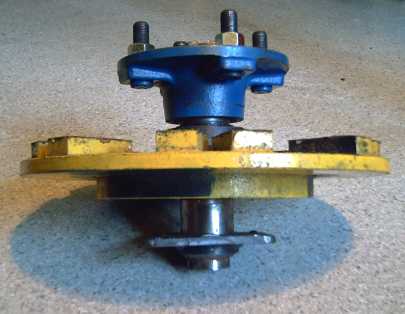
A: Trailer axle with two independently rotating shortened hubs (& the scraps).
B: with magnet rotor. Stator goes on top hub, torque converter/case below on axle.
B: with magnet rotor. Stator goes on top hub, torque converter/case below on axle.
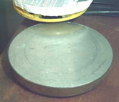
The former frying pan torque converter
"case" with vertical sides. The aluminum insert, which will be cut into
a ring as drawn, can slide in and out for adjustment after assembly.
(screws in slots.) That couples magnetically through a small air gap to
twentyfour 1" x 1" x 1/2" supermagnets of alternating polarities at the
outer edge, bottom side of the motor's driven rotor (yellow). More magnets can be added as a second row inside that if necessary.
Car Turn Signal Lights Wiring: Too Simple!
All along I've realized that for running on electricity the signal lights were going to have to work with the car ignition on "Acc" and not just "Engine on". (More recent cars will probably have additional wiring twists.) I wasn't looking forward to having to do wiring on the car in the tight recess behind the fuse box. Then it hit me that individual wires could be connected to the fuse pin sockets. All that was needed was to take a circuit that ran on "Acc" (radio), and plug a pin into the supply side of that fuse with a wire going to two fuse sockets. Then on the load side wires, connect one fuse back to the radio, and the other to the signal lights.
In fact, I couldn't get the radio fuse (which was labelled "Radio 2") to work on "Acc", so for now I connected to the dome light supply instead. (So now I have to be sure not to leave the turn signals on when I park - the continued clicking sound is the warning!)
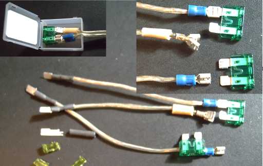
The fuse arrangement for the turn signal lights. Note the double socket soldered onto one of the three wires, and the flat lugs. (For those I just snipped the plastic off a couple of blown fuses with side cutters, soldered each pin and insulated with heat shrink. But that type of flat lug crimp-on connector, the mate for the sockets ends, is available in stores.)
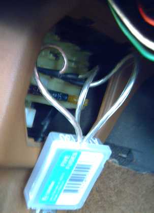
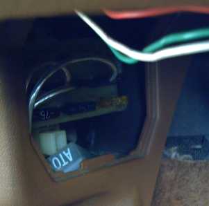
The fuses go in a little hinged plastic box (that they're sold in!) with an entry for the wires clipped out, so there's no exposed metal. (I bent the pins of the fuses a bit to the common wire to fit them in better.) Conveniently, there's room to fit the box in under the car's fuse panel cover by the driver's left knee. (You'd have to ask the car's previous owner about the three exposed (stereo?) wires.)
Motor Controller Circuit Improvements
With the high stopped rotor currents, I decided that 4 Hz must be a bit low of a frequency for the protection circuit. I upped it to 10 Hz by changing a resistor. Stopped rotor and low speed performance remain to be evaluated.
I've been using an LM339 (quad comparitor chip) based PWM generator circuit that, with the protection circuit, uses quite a lot of resistors and capacitors as well as some diodes and a transistor. There was a 555 timer based circuit posted at DPRG that used half as many such parts, but I didn't see how to add in the low speed protection. I puzzled over it for many evenings near the beginning of the month, and on April 5th I finally saw a way to do it. So that's the circuit that's shown in the manual.
I also found that it would be best to add a chip (quad AND or NAND gates) to disable the three MGD inputs to do the PWM, rather than to simply to pulse the LEDs on and off. First, daylight getting into the optics (ie, cover is off the motor) activates the phototransistors ('FT's) even when the LEDs are off, disabling the low speed protection circuit along with everything else, all resulting in blown fuses and transistors. Second, if the motor isn't to be directly coupled to the wheel a tachometer may be valuable, and counting the FT pulses is the obvious way to implement a tachometer - three pulses per revolution so multiply pulses/second by 20 to get RPM. If the LED's (and hence the FT's) are pulsing on and off, it wrecks the count.
Then, I realized ungated FT outputs allowed a simpler, and probably better, circuit for low speed detection using the transitions of just one phase. And the inversion doesn't matter, so the input can be taken from the XOR gate output, which has much more drive capability than the rather feeble phototransistors. I found the circuit could be made from one XOR gate (simply as an inverter) and one AND gate: the two left-over gates from the 3-phase direction control and PMW gating chips. That eliminates the previous 3-input NOR gate, bringing the improved circuit back down to 4 chips total, same as the original, with fewer other components - talk about win-win!
Of course, the improved circuits will be incorporated in the next version of the controller, which I expect to design and make a PCB for, for easy assembly and replication.
I also found, on the 27th at Peden RV for just $27, the "solenoid" (12 volt coil contactor relay) needed to turn the motor power on and off from the ignition key. (Tekonsha, P/N 53536.) It's a little under spec on current rating (70 amps), but the motor (we trust) won't be running when it's switched on or off, which makes a big difference.
A tricky point is that (with the "basic" motor controller) we really want the motor power on with the key on "Acc", but off again when it's on "On" to drive on gas. Since there's no such circuit I may well just settle, at least for now, for keeping the Fwd-Off-Rev switch on Off for gas driving, with the motor power still On but doing nothing.
Other than that detail, finding a suitable relay for a reasonable price seemed to be the hard part - I've looked before and the best I came up with was one from "Cole-Hersee: $100 by special order". Wiring it up should be simple.
All along I've realized that for running on electricity the signal lights were going to have to work with the car ignition on "Acc" and not just "Engine on". (More recent cars will probably have additional wiring twists.) I wasn't looking forward to having to do wiring on the car in the tight recess behind the fuse box. Then it hit me that individual wires could be connected to the fuse pin sockets. All that was needed was to take a circuit that ran on "Acc" (radio), and plug a pin into the supply side of that fuse with a wire going to two fuse sockets. Then on the load side wires, connect one fuse back to the radio, and the other to the signal lights.
In fact, I couldn't get the radio fuse (which was labelled "Radio 2") to work on "Acc", so for now I connected to the dome light supply instead. (So now I have to be sure not to leave the turn signals on when I park - the continued clicking sound is the warning!)
The fuse arrangement for the turn signal lights. Note the double socket soldered onto one of the three wires, and the flat lugs. (For those I just snipped the plastic off a couple of blown fuses with side cutters, soldered each pin and insulated with heat shrink. But that type of flat lug crimp-on connector, the mate for the sockets ends, is available in stores.)
The fuses go in a little hinged plastic box (that they're sold in!) with an entry for the wires clipped out, so there's no exposed metal. (I bent the pins of the fuses a bit to the common wire to fit them in better.) Conveniently, there's room to fit the box in under the car's fuse panel cover by the driver's left knee. (You'd have to ask the car's previous owner about the three exposed (stereo?) wires.)
Motor Controller Circuit Improvements
With the high stopped rotor currents, I decided that 4 Hz must be a bit low of a frequency for the protection circuit. I upped it to 10 Hz by changing a resistor. Stopped rotor and low speed performance remain to be evaluated.
I've been using an LM339 (quad comparitor chip) based PWM generator circuit that, with the protection circuit, uses quite a lot of resistors and capacitors as well as some diodes and a transistor. There was a 555 timer based circuit posted at DPRG that used half as many such parts, but I didn't see how to add in the low speed protection. I puzzled over it for many evenings near the beginning of the month, and on April 5th I finally saw a way to do it. So that's the circuit that's shown in the manual.
I also found that it would be best to add a chip (quad AND or NAND gates) to disable the three MGD inputs to do the PWM, rather than to simply to pulse the LEDs on and off. First, daylight getting into the optics (ie, cover is off the motor) activates the phototransistors ('FT's) even when the LEDs are off, disabling the low speed protection circuit along with everything else, all resulting in blown fuses and transistors. Second, if the motor isn't to be directly coupled to the wheel a tachometer may be valuable, and counting the FT pulses is the obvious way to implement a tachometer - three pulses per revolution so multiply pulses/second by 20 to get RPM. If the LED's (and hence the FT's) are pulsing on and off, it wrecks the count.
Then, I realized ungated FT outputs allowed a simpler, and probably better, circuit for low speed detection using the transitions of just one phase. And the inversion doesn't matter, so the input can be taken from the XOR gate output, which has much more drive capability than the rather feeble phototransistors. I found the circuit could be made from one XOR gate (simply as an inverter) and one AND gate: the two left-over gates from the 3-phase direction control and PMW gating chips. That eliminates the previous 3-input NOR gate, bringing the improved circuit back down to 4 chips total, same as the original, with fewer other components - talk about win-win!
Of course, the improved circuits will be incorporated in the next version of the controller, which I expect to design and make a PCB for, for easy assembly and replication.
"Solenoid" Power Relay
I also found, on the 27th at Peden RV for just $27, the "solenoid" (12 volt coil contactor relay) needed to turn the motor power on and off from the ignition key. (Tekonsha, P/N 53536.) It's a little under spec on current rating (70 amps), but the motor (we trust) won't be running when it's switched on or off, which makes a big difference.
A tricky point is that (with the "basic" motor controller) we really want the motor power on with the key on "Acc", but off again when it's on "On" to drive on gas. Since there's no such circuit I may well just settle, at least for now, for keeping the Fwd-Off-Rev switch on Off for gas driving, with the motor power still On but doing nothing.
Other than that detail, finding a suitable relay for a reasonable price seemed to be the hard part - I've looked before and the best I came up with was one from "Cole-Hersee: $100 by special order". Wiring it up should be simple.