Inevitably, having entered the Electric Hubcap in the New Ventures BC competition, I spent considerable time doing up a business plan. I don't know what the judges will think of it, but it has some unusual aspects - such as "open technology" and welcoming competition - that fly in the face of expected "standard business strategies" and should make for interesting reading!
Work on the reconfigured motor and torque converter proceeded at a leisurely pace. By the middle of the month, the motor spun on the car (I have no other mount for it) without the torque converter ready. Without having to turn the car wheel, it accelerated much more quickly and the current draw was much lower.
I finished the first trial torque converter on the 19th, but I only had four weaker supermagnets available, which I stuck on with double sided carpet tape. It transfers torque with slip, allowing the motor to run faster than the wheel, but the actual torque at the wheel isn't higher: it's a "torque resistor" instead of a "torque transformer". I cut some radial slots in the induced rotor that made it into a better rotor - a "non-linear torque resistor" with a torque curve more like an induction motor rotor (a la NEMA "Type D").
But like the fluid torque converter, it needs a third element: a non-spinning fulcrum that converts the magnetic torque from the motor into electricity, and then the electricity back into "geared down" magnetic motion at the output rotor. This should work - and is probably potentially quite efficient (ie, better than a gear; certainly better than a fluid torque converter) - and I'm now figuring out the hazily glimpsed details of actual operation.
I made a nickel iron battery and, while one wouldn't call it a success as such, in making a chemistry that's known to work and analyzing the results, I've clarified some important battery design details in my mind that should make quite a difference on the next attempt.
May also finally saw the end of the long continued unpleasant weather, considerably assisting doing work outdoors.
The Electric
HubcapTM Vehicle Drive Motor
April In
Detail
Magnetic Torque Converter: Torque Leverage Without Gears
The magnets were ordered near the beginning of May, but there were some
delays owing to travels of the person I ordered them from. They finally arrived on the 29th. However, I
stuck four "lesser" supermagnets on the rotor with double sided carpet
tape and mounted everything on the car to try it out, on May 20th.
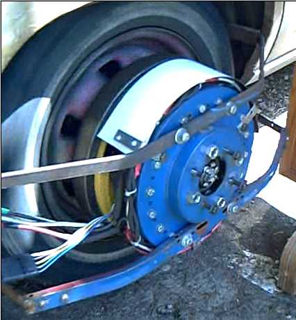
The motor with torque converter spinning the (jacked up) car wheel.
From the movie: http://www.saers.com/~craig/EH-TorqConv1.AVI [24 MB]
It worked quite nicely, the rotor quickly spinning up and the wheel soon catching up. I figured if it went too fast the magnets would pull loose and maybe cause troubles, so I didn't work it very hard. A couple of them shifted a little anyway.
In an induction motor, the AC voltages in the coils make a rotating magnetic field. In the torque converter, the rotating supermagnets make a rotating magnetic field. Their effect on the rotor they turn is the same, except the supermagnet fields are very strong and use no electricity per se.
If you put a tin can or an aluminum cylinder into an induction motor as a rotor, it will spin. But it won't have very good characteristics. Likewise with the flat aluminum plate - it's just a "slip plate" that transfers torque linearly with slip.
An axial flux equivalent of an induction motor rotor, something along the lines of a NEMA "Type D" rotor, will directionize the induced current and retain high rotary torque from speed zero until the slip is small.
But the whole configuration just dissipates the energy of the slipping as heat and there's no more torque than the motor has regardless of slip.
A third element is needed. In the fluid torque converter, there's an impeller that throws the fluid out from the center to the sides, a turbine that redirects the fluid sideways, producing rotary force that varies with the amount of speed slip, and a stator that catches that the back-spraying fluid and redirects it again to "nullify" the unwanted "equal and opposite reaction" force.
Just as the stator won't turn backwards, the magnetic one needs a stationary component for the high torque at the output to push against without pushing directly on the lower torque input. And just as the stator has to redirect the fluid flow, this component must transfer the force by using the generated electricity to create a second magnetic field, that turns the output rotor at lower speed and higher torque.
Based on what info I managed to find about different induction motor designs, I cut radial slits in the aluminum plate across the path swept by the magnets, a slightly skewed slit every 10 degrees (27-28th). Perhaps 72 slits/72 conductor channels would be better, but it does seem to have better torque until levels of slip are small even with the 36. On the other hand, on the 29th the magnets finally arrived and so the test had far better coupling flux available, making comparison difficult.
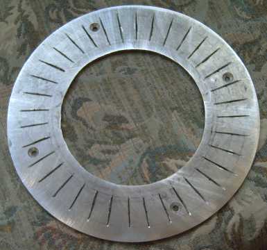
Torque converter's slotted induction rotor.
Before I went to glue them on, I realized that with 12 magnets and 36 slots, they would repeatedly all line up at once and probably cause considerable vibration. I should have cut 37 slots instead of 36. The next most obvious thing to do would be to use 11 magnets instead of 12, but that would entail two like poles next to each other and non symmetry, so I put on just 10.
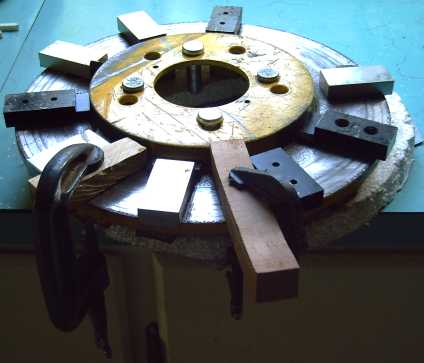
Gluing the 10 high-grade (42 MGoe?) magnets on the back of the motor rotor. The first 5 are easy - they're well separated. The next five between them could get tricky, though the spacing was much easier than with 18 or even 12 magnets, and I simply C-clamped block of wood beside the first magnets to ensure the new one didn't get sucked over to the magnet on one side or the other.
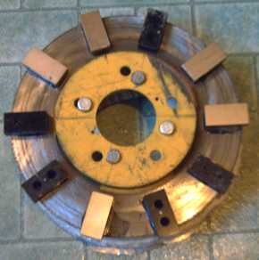
The completed motor/torque converter rotor, torque converter side. (Needs repainting!) Counting both sides: 22 high-grade supermagnets.
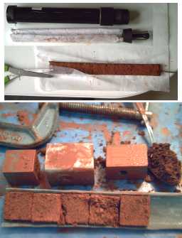
The reason metal plates are held up as they pass near strong magnets is because the magnets generate electricity into them as they move by. The electrons running around inside the metal generate an equal magnetic counter field that opposes the motion. In an induction motor rotor, the electrons are directed along certain paths to magnify the effect.
The magnitude of the difference of the "braking" effect in different metals took me by surprise. It would seem the effect is directly proportional to the conductivity of the metal:
Aluminum resisted motion strongly, but nickel-brass just seemed to slip over the magnets almost effortlessly. This was where I noticed the difference. Then I tried similar pieces of aluminum and copper. I took no measurements, but the copper indeed seemed to resist motion a little more strongly than the aluminum. I suppose the fabled room temperature superconductors would push through the field very sluggishly. (Where are those, anyway? It seemed so promising: multiple new substances that superconducted at higher and higher temperatures, getting up from near absolute zero towards "Antarctic winter" temperatures 20 years ago. Then the research seemed to stop. Key researcher retire? Funding canceled? Ran out of ideas?)
Considering the price and weight of copper, I'll use aluminum for the torque converter. In typical induction motors, the magnetism is transferred by iron laminates on the rotor and much less copper or aluminum is needed. I'm guessing this configuration is actually better with just the aluminum plate and no iron.
The motor with torque converter spinning the (jacked up) car wheel.
From the movie: http://www.saers.com/~craig/EH-TorqConv1.AVI [24 MB]
It worked quite nicely, the rotor quickly spinning up and the wheel soon catching up. I figured if it went too fast the magnets would pull loose and maybe cause troubles, so I didn't work it very hard. A couple of them shifted a little anyway.
In an induction motor, the AC voltages in the coils make a rotating magnetic field. In the torque converter, the rotating supermagnets make a rotating magnetic field. Their effect on the rotor they turn is the same, except the supermagnet fields are very strong and use no electricity per se.
If you put a tin can or an aluminum cylinder into an induction motor as a rotor, it will spin. But it won't have very good characteristics. Likewise with the flat aluminum plate - it's just a "slip plate" that transfers torque linearly with slip.
An axial flux equivalent of an induction motor rotor, something along the lines of a NEMA "Type D" rotor, will directionize the induced current and retain high rotary torque from speed zero until the slip is small.
But the whole configuration just dissipates the energy of the slipping as heat and there's no more torque than the motor has regardless of slip.
A third element is needed. In the fluid torque converter, there's an impeller that throws the fluid out from the center to the sides, a turbine that redirects the fluid sideways, producing rotary force that varies with the amount of speed slip, and a stator that catches that the back-spraying fluid and redirects it again to "nullify" the unwanted "equal and opposite reaction" force.
Just as the stator won't turn backwards, the magnetic one needs a stationary component for the high torque at the output to push against without pushing directly on the lower torque input. And just as the stator has to redirect the fluid flow, this component must transfer the force by using the generated electricity to create a second magnetic field, that turns the output rotor at lower speed and higher torque.
Based on what info I managed to find about different induction motor designs, I cut radial slits in the aluminum plate across the path swept by the magnets, a slightly skewed slit every 10 degrees (27-28th). Perhaps 72 slits/72 conductor channels would be better, but it does seem to have better torque until levels of slip are small even with the 36. On the other hand, on the 29th the magnets finally arrived and so the test had far better coupling flux available, making comparison difficult.
Torque converter's slotted induction rotor.
Before I went to glue them on, I realized that with 12 magnets and 36 slots, they would repeatedly all line up at once and probably cause considerable vibration. I should have cut 37 slots instead of 36. The next most obvious thing to do would be to use 11 magnets instead of 12, but that would entail two like poles next to each other and non symmetry, so I put on just 10.
Gluing the 10 high-grade (42 MGoe?) magnets on the back of the motor rotor. The first 5 are easy - they're well separated. The next five between them could get tricky, though the spacing was much easier than with 18 or even 12 magnets, and I simply C-clamped block of wood beside the first magnets to ensure the new one didn't get sucked over to the magnet on one side or the other.
The completed motor/torque converter rotor, torque converter side. (Needs repainting!) Counting both sides: 22 high-grade supermagnets.
Inductance by Magnets
The reason metal plates are held up as they pass near strong magnets is because the magnets generate electricity into them as they move by. The electrons running around inside the metal generate an equal magnetic counter field that opposes the motion. In an induction motor rotor, the electrons are directed along certain paths to magnify the effect.
The magnitude of the difference of the "braking" effect in different metals took me by surprise. It would seem the effect is directly proportional to the conductivity of the metal:
| Metal |
Resistivity (nano-ohm- meters) |
| Silver |
15.9 |
| Copper |
17.2 |
| Gold |
24.4 |
| Aluminum |
28.2 |
| Brass |
~65 |
| Nickel-Brass ("Nickel-Silver") |
~200 |
Aluminum resisted motion strongly, but nickel-brass just seemed to slip over the magnets almost effortlessly. This was where I noticed the difference. Then I tried similar pieces of aluminum and copper. I took no measurements, but the copper indeed seemed to resist motion a little more strongly than the aluminum. I suppose the fabled room temperature superconductors would push through the field very sluggishly. (Where are those, anyway? It seemed so promising: multiple new substances that superconducted at higher and higher temperatures, getting up from near absolute zero towards "Antarctic winter" temperatures 20 years ago. Then the research seemed to stop. Key researcher retire? Funding canceled? Ran out of ideas?)
Considering the price and weight of copper, I'll use aluminum for the torque converter. In typical induction motors, the magnetism is transferred by iron laminates on the rotor and much less copper or aluminum is needed. I'm guessing this configuration is actually better with just the aluminum plate and no iron.
EH Motor Power
W = V *
A. Given 36 volts, the watts being consumed by the motor depends on
the amps flowing. Early on, I measured the battery current as 30 A
while one phase was 20 A. This was in accord with theory: each phase is
only driven 2/3 of the time.
My multimeter only reads up to 30 A and my AC clamp-on ammeter can only measure the AC phase current, not the DC battery current. With 100 amps, using the DC meter would ruin it, so I only used the clamp-on on one phase. Somewhere along the line, I got confused and stopped multiplying by 1.5. I came up with 36V * 100A = 3600 watts or 4.82 horsepower.
But a measured 100 amps means 150 amps total draw, so the correct calculation is 36 V * 150 A = 5400 W or 7.23 HP. That seems much more satisfactory... but copper loss calculations show that the efficiency at high powers will be lower than expected, and the actual top horsepower output will still be about 5-6.
As an aside on the same subject, the motor needed some reconfiguring for the torque converter: hubs machined, optical system remade for a larger diameter "can", and the mounting arms changed to fit as the stator now sits farther out from the wheel. For the first time, however, I could have the motor spin without having it spin the car wheel, as it is no longer directly connected to it and the torque converter isn't installed yet.
Just spinning its own rotor, it reads around 10 amps (meaning - ahem! - 15 amps from the batteries), whereas while spinning the car wheel IIRC it read around 40 (= 60) or more. That's probably a fair indication of how much friction is involved simply in turning all the bearings and seals, churning up the oil in the differential and turning the differential gears, with turning the wheel, axle and rear driveshaft. (Also, I should try ditching those metal coil clamps and make nylon ones. It would probably drop a few more amps.)
As an aside to the aside, I don't know the RPMs involved. I'm pretty sure it was going faster without the wheel. (1500-2000 RPM?) I didn't put it on full power without knowing the RPM - it started humming, making me nervous! I really want a new version of the motor controller that will let me measure RPM! Now that I've improved the circuit, somebody has given me a link to a "3 phase brushless motor controller" chip that should do the job with less parts, ON Semiconductor's MC33033. I ordered a few Saturday night and they arrived Tuesday, the first business day. I guess queen Victoria's birthday wasn't a holiday in the US.
So... how much power does it actually take to drive a car? I've recently had converse with someone who converted an old car. He took out the gas engine (evidently), and put a in 4 HP DC electric motor to drive it via the regular transmission. He said GVW is 900 Kg (2000 pounds).
He said he expected to stay in first gear and be able to go up to 20 Km/Hr through his cow pastures. What he actually found was that it could spin the front wheels in first gear (presumably on dirt) and attain 45 Km/Hr in third on his rough dirt trails. He figured it would easily do 50 on level pavement.
Now, that motor was operating through the lossy vehicle transmission, typically 30% loss. (Also it was with some crappy old batteries. Encouraged by the performance, he's ordered some new batteries to see what it can do with those!)
If the Electric Hubcap on the wheel actually performs 50% better as expected, then 5.4 HP * 1.5 ~= 8.1 HP means it would have twice the effective driving power of the 4 HP car that could probably do over 50 Km/Hr on level pavement. Of course, vehicles with gas engines would be heavier than his 2000 pound converted car.
From all this, one might estimate that one Electric Hubcap, with the torque converter for "get-go" and climbing hills, should provide at least enough drive for practical city driving. This is in accord with previous optimistic estimates.
My multimeter only reads up to 30 A and my AC clamp-on ammeter can only measure the AC phase current, not the DC battery current. With 100 amps, using the DC meter would ruin it, so I only used the clamp-on on one phase. Somewhere along the line, I got confused and stopped multiplying by 1.5. I came up with 36V * 100A = 3600 watts or 4.82 horsepower.
But a measured 100 amps means 150 amps total draw, so the correct calculation is 36 V * 150 A = 5400 W or 7.23 HP. That seems much more satisfactory... but copper loss calculations show that the efficiency at high powers will be lower than expected, and the actual top horsepower output will still be about 5-6.
As an aside on the same subject, the motor needed some reconfiguring for the torque converter: hubs machined, optical system remade for a larger diameter "can", and the mounting arms changed to fit as the stator now sits farther out from the wheel. For the first time, however, I could have the motor spin without having it spin the car wheel, as it is no longer directly connected to it and the torque converter isn't installed yet.
Just spinning its own rotor, it reads around 10 amps (meaning - ahem! - 15 amps from the batteries), whereas while spinning the car wheel IIRC it read around 40 (= 60) or more. That's probably a fair indication of how much friction is involved simply in turning all the bearings and seals, churning up the oil in the differential and turning the differential gears, with turning the wheel, axle and rear driveshaft. (Also, I should try ditching those metal coil clamps and make nylon ones. It would probably drop a few more amps.)
As an aside to the aside, I don't know the RPMs involved. I'm pretty sure it was going faster without the wheel. (1500-2000 RPM?) I didn't put it on full power without knowing the RPM - it started humming, making me nervous! I really want a new version of the motor controller that will let me measure RPM! Now that I've improved the circuit, somebody has given me a link to a "3 phase brushless motor controller" chip that should do the job with less parts, ON Semiconductor's MC33033. I ordered a few Saturday night and they arrived Tuesday, the first business day. I guess queen Victoria's birthday wasn't a holiday in the US.
Motor Efficiency: Copper Losses
I've said the EH
should have lower copper losses. However, here are some actual calculations. (Ugh, math!) Resistance of the #14 gauge coil wire
is .008282 ohms/meter (roughly!), and there's about 12 meters of wire in each
coil.
As long as the motor is turning - and with the torque converter, it's never "stuck" - the waveform is AC. When the battery is supplying the maximum of 150 amps DC (very nominally!), each phase reads 100 amps AC. As the phases have three coils in parallel, one sees each coil as a having an AC waveform of 33 amps RMS.
.008282 * 12 = .099 ohms
.099 * 33 sqrd. = 108 W (in each coil)
108 * 9 = 970 W
That's waste heat. I don't think we're in "needs liquid cooling" territory yet, but certainly it's getting up there. Air had certainly better be flowing past the coils.
Also with 150 amps flowing, the total power consumption is
36 V * 150 A = 5400 W (= consuming 7.2 HP)
(5400-970) / 5400
= 4430 / 5400
= 82% efficiency. (5400 = 7.2 HP; 4430 W = only 5.9 HP out; loss: 1.3 HP!)
And that's only considering copper losses. (Could we please have those mystical room temperature superconductors?)
Somehow that isn't the "90+%" I've been speaking of!
Well, let's try it at 50% load, which will presumably be more common than "floored".
16.5 A squared * .099 ohms = 272 * .099 = 27 W
27 W * 9 coils = 243 W (1/4 as much waste heat)
75 A * 36 V = 2700 W (Total input power - 1/2 as much)
(2700-243) / 2700 = 91%. (2700 W = 3.6 HP in; 2457 W = 3.3 HP out, loss: .325 HP)
1/2 the power but only 1/4 as much loss, and over 90% efficiency: that's more like it!
At such high currents, even the main power leads from the batteries to the controller and from there to the motor have losses. For example, at 100 amps, the wires from the controller to the motor (and back - over 7' in all) lose about 1/2 volt, which (W = V * A) is 50 watts.
Here's a table based on 90 max amps phase reading or 135 DC battery amps, which is probably closer than my rounded off "150 amps" (again, considering only copper losses):
With copper loss energy being proportional to the square of the current, evidently serious copper losses are occasioned by high currents, but the losses shrink towards insignificance as the current is reduced. All motors will suffer similarly in varying degree.
There are of course other causes of inefficiency which will lower the figures somewhat: iron losses; bearing friction; air friction. The torque converter also has significant losses, but (we may anticipate) less than an automotive transmission. The friction losses of the car tires, wheels, differential gears and drive shafts overshadows all this, adding a lot to the required power.
Cruising down a street, a car drive will tend to be lightly loaded rather than nearly "floored" a lot of the time, and hence in the better efficiency range. Exceptions are going up hills, highway speeds, and stop and go traffic lights every block. Long uphill grades (city or highway) are likely to occasion the greatest heating of the motors.
After doing all the above, in the last torque converter test the maximum readings I saw with the motor running steady (working hard to drive the stopped torque converter) were between the first two table entries, about 75 amps (25 amps per coil), or 112 DC amps from the battery. The 90 or 100 amp readings were probably with the rotor stopped or just starting to turn.
Obviously the efficiency at high currents is related to the size of wire used. That's limited by what actually fits on the coil.
Somewhere I found a "rule of thumb" guide for the size of wire to use for "X" amps flowing in a coil, and it indicated that the #14 size I chose was about right for 30 amps max. It used some number, 4XXX and AWG in some formula, and said it was conservative. I've tried to find it again without success.
Looking again, I see other guides, but they're frustratingly scarce. Partly the problem is finding good search terms to narrow down the search:
* 500 circular mills per ampere.
* 10 A/mm^2. ("However, the maximum current density is really determined by how well the design can get the heat produced via resistive losses out.")
For the first guide rule, I get 8.1 amps. For the second, #14 wire is 1.63mm diameter or 1.3 square mm, or 13 amps. The previous guide said, as best I can recall, about 30.
So the guide rules are not only hard to find, they're wildly inconsistent with each other. Of course, the motor would be more efficient at high currents if so much copper as these latter two ask for could actually fit on the coils! Radial flux motors do fare better in this regard, having more electromagnet iron and so more space for the copper. On the other hand, this increases their iron losses, and they weigh more.
I also ran across an ARRL handbook figure for runs of #14 wire: 32 amps in open air and 17 in a cable, which shows the importance of being able to dissipate the heat. That's why the Electric Hubcap coils are open to the air on all sides and the rotor magnets will fan them as it spins. It is reassuring that with the torque converter the motor will now always be spinning when it's powered.
The lighter weight is a contribution to letting the EH mount on a car wheel. Nevertheless an objection that may be raised to its use is the extra unsprung weight - It certainly doesn't improve the handling. I'm considering whether there may be some way to allow the outer and heavier part of the motor be able to spring up and down to some extent. The axle would have to pivot where it connects to the wheel, which would require some sort of "U-joint" or "CV joint" mechanism.
The idea may or may not be practical. Almost inevitably the motor would stick out a little farther from the wheel. As minimums now, 2.5" for the motor, about 2" for the torque converter (as currently visualized), and maybe 1.5" so the flexing unit doesn't hit the wheel when going over speed bumps: 6" even with specially made rotors.
As long as the motor is turning - and with the torque converter, it's never "stuck" - the waveform is AC. When the battery is supplying the maximum of 150 amps DC (very nominally!), each phase reads 100 amps AC. As the phases have three coils in parallel, one sees each coil as a having an AC waveform of 33 amps RMS.
.008282 * 12 = .099 ohms
.099 * 33 sqrd. = 108 W (in each coil)
108 * 9 = 970 W
That's waste heat. I don't think we're in "needs liquid cooling" territory yet, but certainly it's getting up there. Air had certainly better be flowing past the coils.
Also with 150 amps flowing, the total power consumption is
36 V * 150 A = 5400 W (= consuming 7.2 HP)
(5400-970) / 5400
= 4430 / 5400
= 82% efficiency. (5400 = 7.2 HP; 4430 W = only 5.9 HP out; loss: 1.3 HP!)
And that's only considering copper losses. (Could we please have those mystical room temperature superconductors?)
Somehow that isn't the "90+%" I've been speaking of!
Well, let's try it at 50% load, which will presumably be more common than "floored".
16.5 A squared * .099 ohms = 272 * .099 = 27 W
27 W * 9 coils = 243 W (1/4 as much waste heat)
75 A * 36 V = 2700 W (Total input power - 1/2 as much)
(2700-243) / 2700 = 91%. (2700 W = 3.6 HP in; 2457 W = 3.3 HP out, loss: .325 HP)
1/2 the power but only 1/4 as much loss, and over 90% efficiency: that's more like it!
At such high currents, even the main power leads from the batteries to the controller and from there to the motor have losses. For example, at 100 amps, the wires from the controller to the motor (and back - over 7' in all) lose about 1/2 volt, which (W = V * A) is 50 watts.
Here's a table based on 90 max amps phase reading or 135 DC battery amps, which is probably closer than my rounded off "150 amps" (again, considering only copper losses):
| % of FULL POWER AMPS |
POWER IN (W HP) |
POWER OUT (W HP) |
POWER LOSS (W HP) |
EFFICIENCY % (Cu losses only) |
| 100 135 |
4860 6.5 |
4058 5.4 |
802 1.1 |
84 |
| 75 101 |
3636 4.9 |
3186 4.3 |
450 .6 |
88 |
| 2/3 90 |
3240 4.33 |
2884 3.86 |
346 .47 |
89 |
| 50 67 |
2430 3.25 |
2232 3.00 |
198 .26 |
92 |
| 1/3 45 |
1620 2.17 |
1531 2.05 |
89 .12 |
95 |
| 25 34 |
1224 1.64 |
1173 1.57 |
51 .07 |
96 |
With copper loss energy being proportional to the square of the current, evidently serious copper losses are occasioned by high currents, but the losses shrink towards insignificance as the current is reduced. All motors will suffer similarly in varying degree.
There are of course other causes of inefficiency which will lower the figures somewhat: iron losses; bearing friction; air friction. The torque converter also has significant losses, but (we may anticipate) less than an automotive transmission. The friction losses of the car tires, wheels, differential gears and drive shafts overshadows all this, adding a lot to the required power.
Cruising down a street, a car drive will tend to be lightly loaded rather than nearly "floored" a lot of the time, and hence in the better efficiency range. Exceptions are going up hills, highway speeds, and stop and go traffic lights every block. Long uphill grades (city or highway) are likely to occasion the greatest heating of the motors.
After doing all the above, in the last torque converter test the maximum readings I saw with the motor running steady (working hard to drive the stopped torque converter) were between the first two table entries, about 75 amps (25 amps per coil), or 112 DC amps from the battery. The 90 or 100 amp readings were probably with the rotor stopped or just starting to turn.
Coil Wire Size
Obviously the efficiency at high currents is related to the size of wire used. That's limited by what actually fits on the coil.
Somewhere I found a "rule of thumb" guide for the size of wire to use for "X" amps flowing in a coil, and it indicated that the #14 size I chose was about right for 30 amps max. It used some number, 4XXX and AWG in some formula, and said it was conservative. I've tried to find it again without success.
Looking again, I see other guides, but they're frustratingly scarce. Partly the problem is finding good search terms to narrow down the search:
* 500 circular mills per ampere.
* 10 A/mm^2. ("However, the maximum current density is really determined by how well the design can get the heat produced via resistive losses out.")
For the first guide rule, I get 8.1 amps. For the second, #14 wire is 1.63mm diameter or 1.3 square mm, or 13 amps. The previous guide said, as best I can recall, about 30.
So the guide rules are not only hard to find, they're wildly inconsistent with each other. Of course, the motor would be more efficient at high currents if so much copper as these latter two ask for could actually fit on the coils! Radial flux motors do fare better in this regard, having more electromagnet iron and so more space for the copper. On the other hand, this increases their iron losses, and they weigh more.
I also ran across an ARRL handbook figure for runs of #14 wire: 32 amps in open air and 17 in a cable, which shows the importance of being able to dissipate the heat. That's why the Electric Hubcap coils are open to the air on all sides and the rotor magnets will fan them as it spins. It is reassuring that with the torque converter the motor will now always be spinning when it's powered.
Suspension
The lighter weight is a contribution to letting the EH mount on a car wheel. Nevertheless an objection that may be raised to its use is the extra unsprung weight - It certainly doesn't improve the handling. I'm considering whether there may be some way to allow the outer and heavier part of the motor be able to spring up and down to some extent. The axle would have to pivot where it connects to the wheel, which would require some sort of "U-joint" or "CV joint" mechanism.
The idea may or may not be practical. Almost inevitably the motor would stick out a little farther from the wheel. As minimums now, 2.5" for the motor, about 2" for the torque converter (as currently visualized), and maybe 1.5" so the flexing unit doesn't hit the wheel when going over speed bumps: 6" even with specially made rotors.
Driving Power
So... how much power does it actually take to drive a car? I've recently had converse with someone who converted an old car. He took out the gas engine (evidently), and put a in 4 HP DC electric motor to drive it via the regular transmission. He said GVW is 900 Kg (2000 pounds).
He said he expected to stay in first gear and be able to go up to 20 Km/Hr through his cow pastures. What he actually found was that it could spin the front wheels in first gear (presumably on dirt) and attain 45 Km/Hr in third on his rough dirt trails. He figured it would easily do 50 on level pavement.
Now, that motor was operating through the lossy vehicle transmission, typically 30% loss. (Also it was with some crappy old batteries. Encouraged by the performance, he's ordered some new batteries to see what it can do with those!)
If the Electric Hubcap on the wheel actually performs 50% better as expected, then 5.4 HP * 1.5 ~= 8.1 HP means it would have twice the effective driving power of the 4 HP car that could probably do over 50 Km/Hr on level pavement. Of course, vehicles with gas engines would be heavier than his 2000 pound converted car.
From all this, one might estimate that one Electric Hubcap, with the torque converter for "get-go" and climbing hills, should provide at least enough drive for practical city driving. This is in accord with previous optimistic estimates.
Optical Commutator & Simplified Motor Controller
Being
unable to find anything like my "optical commutator" on the web, and
seeing a couple of seemingly bizarre and complex PMSM control
techniques widespread
on the web, I had thought that I had probably invented the idea. It did
seem puzzling as it seemed so simple. However, people often miss the
simple and obvious and instead some needlessly complex work is
labouriously hacked out, so I just shrugged.
However, someone has pointed me to a motor controller IC chip that has inputs which could be taken straight from the optical commutator. (MC33033 from "ON Semiconductor".) True the suggested circuit showed three hall effect sensors rather than optics, but the essential principle was there, and the text mentions "slotted optics", implying the chip would expect an optics circuit much like mine as an input. It even has two options for the sensor angles, the other of which, using narrower angles, could shrink my "optical commutator" circuit board.
From the datasheets it looks like this chip tries to do pretty much what the four chips in my controller design do, and with far fewer passive components. Its cycle-by-cycle current limiting eliminates the need for my low speed protection circuit. However its output drivers are only good for lower power motors (and 24 volts or less). It looked like the 28 pin IR2130 mosfet driver chip would still be needed, along with an inverter chip, just to drive the mosfets. But I had missed seeing a whole series of 8 pin "half bridge" MOS driver ICs, eg AUIRS2003S and IRS2183, all with the same pinouts. Three of these small chips driven by the MC33033 should make the whole motor controller other than the power circuits.
Here it was me that missed a simpler solution (did I say I was immune?), and it was my motor controller design that was needlessly complex! I had started in to design a circuit board with the previous circuit; luckily I didn't get very far as the whole circuit will now be changed and considerably simplified.
I was wondering how I was going to find a resistor small enough in value and with enough watts rating to implement the current limiting sensor for over 100 amps. However, having now looked up the resistances of copper wire, it would appear that simply about 6 inches of #12 wire linking to the mosfet ground pins should do the trick!
Micro-Ferrite Coil Cores?
The nail strip cores are great, but is there anything that would be easier to manufacture? I can just see a factory full of people placing nail strips in coils - substantial labour! Ferrite cores would be simpler, but the flux density is too low for a motor.
An interesting element is niobium. Evidently it's strongly paramagnetic and it has the greatest magnetic penetration depth of any element. It might be an interesting idea to try microcrystalline ferrite cores mixed with with niobium or niobium oxide powders. This might give the necessary high flux in a ceramic or porcelain core that can simply be pressed into a mold and baked in a pottery kiln. ..or perhaps a pressed powder core. As paramagnetic material has no magnetic hysteresis, it might be possible to make high flux cores with the "iron losses" reduced to insignificance, increasing the efficiency of the motor.
Then, the core would be used as the spool to wind the coil wire directly onto, saving considerable manipulation steps (labour). Since the ceramic is an electrical insulator, there'd be no need to worry the wire might short to it.
In addition, if it's not struggling to attain enough flux, cooling air channels or grooves might be built into the core form to cool the inner side of the coil wire. If the flux density is sufficient, it might even be possible to shape the cores with smaller diameter in the middle (viz: ")|||(" ) so a larger wire size can be fit in the space, reducing copper losses.
(Hmm, no niobium compounds in the pottery catalog - rats!)