I had some interesting ideas in May and more in June. The result was I had new things happening everywhere. On June 13th I counted at least ten projects started and nothing finished. I felt overwhelmed and decided to take Sunday the 14th off and do nothing on the energy projects. (Doubtless a good idea for every week!) On the 15th I finished three projects, including the "Some Principles of Battery Making" paper, which I posted on the web site. It already needs serious updating.
The next day I found Turquoise Energy had been eliminated from the New Ventures BC competition. Evidently having invented a better future is "laudible" but means nothing compared to the management team by some miracle already involved (for free) in my new inventions, and the minute details of the business plan.
Unlike previous inventions of mine that have gone nowhere through seeming indifference and apathy on the part of anyone with any funds to make them commercial, I've been putting these designs on the web, and the motor at least is simple enough to make at home. (The electric car batteries probably will be too.) As I've said, if no one here cares to make, or to help make, an enterprise of it, at least we'll probably be able to import my car hybridizing kits from China in ten years or so. Oxford university in England may possibly have more or less copied my motor already - at least, they now have a very similar motor.
Canada funds "university research" and "innovative companies". Our few top inventors, if they are truly inventing, are usually working on their own in "post pure research" but "pre-business" areas. New industries may follow invention - they can't precede it. So we don't fit into the funding guidelines of any government R & D funding agency or business capital investors. "Great project! Don't give up! Do try elsewhere." Inventors creating... as the immediate though certainly not exclusive example... priceless means for achieving the sustainable energy future we as a nation avowedly want, are not worth a slice of bread in Canada.
I must be pretty dull witted: it's taken me two decades of chasing chimeras, a decade of poverty, and finally talking to a number of other - invariably unfunded - inventors to figure this out.
On the 24th I e-mailed the finished printed circuit board design for the improved motor controller to Alberta Printed Circuits and got a couple of boards made. One is mounted and about ready to test. That'll make for completely outfitted aluminum wiring box enclosures (8" x 10") containing 3-phase brushless or PMSM motor controllers. The motor ratings (volts, amps, HP) depend simply on a few component choices that can all equally be accommodated. It'll be good to finally have one-offs of ready merchandise, but the goal is complete car hybridizing kits shipping daily by the 1,000's.
A nice design for battery electrodes emerged in June - hollow, perforated nickel [plated] tubes with electrolyte powders and conductive monel metal powder crammed - hammered - into them, separated with, eg, polyester cloth insulators. This is similar to Edison's successful 1910's electric car batteries except there was no plastic back then.
Then, in trying out that design, I created a very superior battery electrode using monel powder as an additive. After all my non-conductive electrodes, this type is so highly conductive it can revise some "givens" - assumptions about how batteries "have to be" made - opening a path to new high power, economical battery designs.
I also spent some time looking up and buying things to use for glazed ceramic microcrystalline electromagnet cores for Electric Hubcap type motors and I've obtained enough clays, minerals and things to try out several formulas. Such coils will make producing the motors much easier (read "cheaper") and hopefully improve their efficiency a bit.
Unfortunately I haven't found the time to put together a key Electric Hubcap part to test it: the magnetic torque converter. It's going to take considerably more machining and metalwork on top of what I've already done. (I have however got a much clearer concept of what needs to be made.)
Someone said that a planetary gear set can be used to make a 3-speed transmission. Hmm... gears, eg 7:1, 3:1 and of course 1:1, would get the motor running on the street. But even using ready made automotive gears, the torque converter should be simpler, with superior performance!
Now for a couple of days of other work, a couple of days of holiday and a couple of days of yard work, and July will be well underway before I get much more done on the projects.
The Electric
HubcapTM Vehicle Drive Motor
June In
Detail
There wasn't a lot of work on the motor per se in June. For one thing, it's finished and running. Other items for car hybridizing - the motor controller and batteries - received most of the attention.
I thought the motor seemed to draw a little much current when idling in May - it seemed to use somewhat more power idling full speed than my lawnmower (15A @ 36V = 540W, versus 4.2A @ 120V = 504W. Of course, it's about 5HP versus under 2HP for the mower), and I knew the metal coil clamps would be a source of inefficiency. I've now replaced them with nylon clamps. So far I haven't reassembled, mounted and run the motor again to see if it draws observably less current. That will come along with trying the new motor controller.
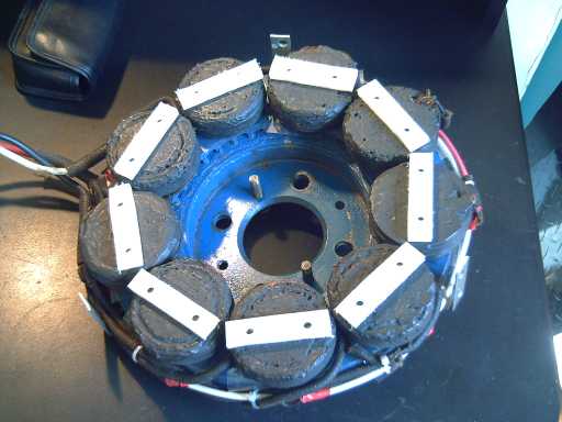
The motor with nylon clamps holding the coils. Only the wide gap to the rotor permits the use of such thick clamp pieces!
Another Geared Wheel Motor: Copycat?
Here's another geared motor evidently intended to drive individual wheels. The large part at the back appears to be the motor, apparently quite similar in size, shape and weight to the Electric Hubcap. The orientation of the coils would appear to indicate it's also axial flux. The white part is evidently a gearbox, with the center piece being a socket for a drive shaft.
http://www.ox.ac.uk/media/news_stories/2009/090508_1.html
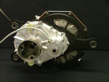
Oxford Motor (rear-right) and gearbox (front-left)
"Dr Malcolm McCulloch of the Electrical Power Group at Oxford's Department of Engineering Science said: 'The motor can achieve high torque for its weight, which ultimately means a smaller and cheaper motor. Torque is the twisting force that accelerates the car, and the peak torque we're aiming for is 500Nm from 25kg.'"
25kg weight is pretty close to that of the Electric Hubcap with the torque converter. Now, if I just had an idea of the EH's torque, I could compare them... but I'll hazard a guess that it's not too dissimilar.
It appears they intend to mount the motors, light as they are, inside the car, with CV drive shafts to the rear wheels. It might be difficult to put them on the wheels with the off-center drive gear.
My design, with the video of the car moving, has been on the web since last October, 8 months. Is that long enough to think they may have copied the design or taken a cue from it? Perhaps not, but who knows? If they did, it shows that putting the idea and designs on the web is already taking it places beyond my personal sphere, and beyond Canada. (If they have a magnetic torque converter in 2010 to replace the gears, that would be quite indicative!)
Some Revised Specs?
In the last tests with the torque converter, the highest motor phase currents
I saw were about 75 amps rather than 90. The 90 I had previously noted
was probably more or less the startup current before the motor really got
going rather than steady run current at speed. With the first prototype torque
converter, and the car wheel on the ground, the load is maximum at high speed but the
motor is able to start turning easily. Using the 75 amps figure, the maximum running
watts is then 112.5 A (battery current to all 3 phases) * 36 V = 4050
W. Copper losses at maximum power would be .099 ohms * 25 A^2 = 62 W (per coil), * 9 coils = 557 Watts. Output power is then 3493 W or 4.67 HP. Efficiency at full power (the worst case) is 86%, all figures considering only copper losses.
New Motor Controller
I designed a new motor controller circuit using the MC33033 brushless motor controller chip and
three "half bridge" MOSFET driver chips, layed out a printed circuit
board (PCB) for it, and e-mailed the design files off to have sample
boards made in Calgary.
The planned aluminum wiring box using this board will be 4-1/2 inches deep, with a planned outline of 8" x 10". The motor controller will occupy one 10 inch removable sidewall. This allows easy wiring access by removing the front cover without disturbing anything, and easy removal of the controller for servicing or replacement. Aluminum heat sink fins sticking out the controller side will make it effectively occupy about 11" x 10".
In a sense, one might better look at the product as "a complete motor wiring connection box with everything built in including the motor controller".
This will essentially be a production prototype - when I'm sure any bugs are worked out, perhaps I may even sell a few as hand production.
The finished boards (2 of) arrived on the 29th. I bought the parts for it that day and assembled it on the next. I soon found two mistakes and corrected them in the PCB layout program for next time. It's so much easier now than with mylar, slit tape and donut pads!
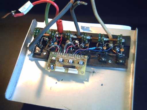
New Motor Controller Circuit Board.
The 2" x 3.5" PCB bolts on via three of the power mosfet mounting screws, saving labor and space.
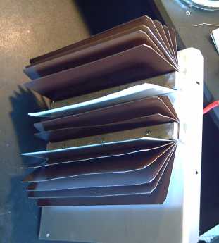
The heat sink fins on the outside, made from aluminum roofing flashing.
The heavy aluminum bars clamp right through the cover panel to the inside bars the power mosfets mount on.
I think I have the theory of operation of the magnetic torque converter
worked out. Trying to work on a dozen projects at once has prevented
getting at it. A new rotor needs to be made and attached with a new set
of bearings.The planned aluminum wiring box using this board will be 4-1/2 inches deep, with a planned outline of 8" x 10". The motor controller will occupy one 10 inch removable sidewall. This allows easy wiring access by removing the front cover without disturbing anything, and easy removal of the controller for servicing or replacement. Aluminum heat sink fins sticking out the controller side will make it effectively occupy about 11" x 10".
In a sense, one might better look at the product as "a complete motor wiring connection box with everything built in including the motor controller".
This will essentially be a production prototype - when I'm sure any bugs are worked out, perhaps I may even sell a few as hand production.
The finished boards (2 of) arrived on the 29th. I bought the parts for it that day and assembled it on the next. I soon found two mistakes and corrected them in the PCB layout program for next time. It's so much easier now than with mylar, slit tape and donut pads!
New Motor Controller Circuit Board.
The 2" x 3.5" PCB bolts on via three of the power mosfet mounting screws, saving labor and space.
The heat sink fins on the outside, made from aluminum roofing flashing.
The heavy aluminum bars clamp right through the cover panel to the inside bars the power mosfets mount on.
Magnetic Torque Converter Project:
Torque Leverage Without Gears
June Details
Torque Leverage Without Gears
June Details
Principles of operation
I seem to have written this up as a "Q & A".
Why does the Electric Hubcap motor need one?
My original idea was that with the large diameter of the axial flux Electric Hubcap motor, the supermagnets had powerful enough magnetic forces to move a car by directly turning a wheel with no gears or transmission. Trouble is, they're being driven by ordinary electromagnets that create a rotating magnetic field to move them, and those fields aren't as strong. The torque can only be as strong as the electromagnets' field, so the motor still needs to be "geared down" to multiply the torque.
The magnetic torque converter seems like a better solution than mechanical gears: it should prove to be simpler, quieter, more efficient, and there are no gears to shift.
Is there a way to get a strong enough rotating field?
Yes, by putting supermagnets on the back side of the motor's rotor. The motor spins and the supermagnets have the powerful field. They can drive a second rotor that's like an induction motor rotor.
So the problem is solved?
No. At this point the second rotor's torque is generated by pushing magnetically against the first rotor, and the first rotor is still being turned by those electromagnets. So the second rotor can't have any more torque than the first one has. Any excess "back torque" simply slows the motor down. The potentially stronger force of the supermagnets is wasted.
How do you get around that "equal and opposite reaction"?
A third piece, a torque converter stator, is required in between the rotors. The spinning motor rotor supermagnets will generate powerful electric current into the aluminum stator. The currents can be immense, but they're easily handled by the whole aluminum body of the flat stator. The currents are directionized by radial slots in the stator across the path of the magnets. They generate a rotating field of the same strength as the supermagnets field but of opposite polarity. This field is generated circling the aluminum "wires", so it's there on the other side of the stator as well. We now have a supermagnet strength rotating field emanating from a stationary piece. The second rotor's thrust will push against that instead of against the motor rotor. The braking force on the first (motor) rotor is electromagnetic friction against the stator, not against the second rotor, so the second rotor can have higher torque than the driving rotor if it's turning slower.
Why doesn't the stator simply act as a magnetic brake on the motor rotor?
That's exactly what happens when the second rotor isn't present, or when it's stopped. But that powerful braking force transfers across the stator disc to become propulsive force acting on the second rotor, and it's strongest when that rotor is stopped.
When it starts to spin, it generates back EMF into the stator. Just like in a regular induction motor, the stator currents drop off as the second rotor speeds up, until if it is rotating the same speed as the motor, the currents and magnetic fields are balanced and null. (Disregarding small losses of course.)
The force thus varies with the difference in speeds between the motor and the wheel. It is full "supermagnet strength" force at low wheel speed and high motor speed, which becomes more moderate as the car speeds up, or when the motor slows down by easing up on the gas pedal.
It's the increase from an "electromagnet strength" rotating field to a "supermagnet strength" one that gives the induction rotor sufficient torque to crank the wheel around and move the car.
The motor is variably "geared down" magnetically to the wheel.
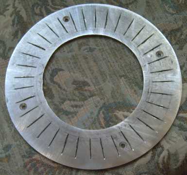
The piece I cut for a rotor becomes the Torque converter's stator disc.
The induction rotor may end up being quite similar.
Microcrystalline Electromagnet Coil Cores
First Details
In May I looked up "microcrystalline cores", which term I'd heard mentioned somewhere and wrote down on a scrap of paper that I found when I cleaned out my wallet. It seems they have better potential than ferrite or "amorphous" cores to replace varnished iron alloy motor/transformer laminate strips, or in this case, my pet concept, the spray painted nail gun finishing nail strips. If it works, it will simplify manufacture of the coils (potentially making the motors considerably cheaper) and no doubt further reduce motor iron losses. The question is, what should they be composed of and how should they be made?
The general possibilities as I see them are:
1) mix clay and magnetic powders such as iron oxide and fire them in a kiln.
2) mix the powders and then mix them into epoxy to make them solid.
3) mix the powders and then saturate them with motor varnish and bake them.
I've decided to try #1, with the addition of glazing the ceramic with a glaze of sodium silicate and paramagnetic minerals once the core is fired. (possibly with the wire coil already wound around it?) The oxide powders are very fine, but it seems to me firing them in a kiln has potential for rearranging crystals into the desired "micro" or "nano" form.
Or, it might just muck things up by making them bigger instead. If results aren't satisfactory, I'll try the other ideas.
Then the details, and with the glaze, started to get more complex than the seemingly simple concept. I ended up with the following materials:
- Vashon Paper Clay - fires at cone 04 to 6, a strong clay with pores for the metal oxide powders to occupy without cracking during firing.
- Laguna B-Mix 5 clay (cone 5). - A very hard porcelain-like clay.
(Probably this should be better, with the next ingredient below - I think I wasted my $1 that I paid for the Vashon clay a couple of days earlier.)
- Crushed kiln brick - Used as a grog to strengthen the clay and to provide pores for the magnetic powders.
- Feldspar - a rock forming mineral. (Harder! - Can't have the cores busting!)
- Gerstley Borate - mineral with boron.
- Sodium Silicate - "Water Glass".
- Ilmenite - natural mineral. Fe:Ti silicate.
- Fine Rutile - natural mineral. Contains paramagnetic elements Ti and (hopefully) some Nb.
- Black Iron Oxide (FeO)
- Red Iron Oxide (Fe2O3)
- Magnetite (Fe3O4)
The plan is to make several cores of widely varying compositions and test them, then take the most promising looking one(s) and try smaller variations around that. (I'll have to take care to document each one carefully, weighing ingredients, timing the firing, firing temperature, etc.)
The field strength test will probably consist of putting a supermagnet on a spacer above the coil and seeing how thick a spacer can be inserted and still have the magnet rise up (repel) when the coil is energized, using the same coil wire, voltage and magnet for each test.
Finished motor coils could be prime merchandise for Turquoise Energy to sell to DIY motor makers if no capital is forthcoming to start making complete hybridization kits. With motor controllers (complete with wiring boxes) and coil cores, making a 5-6 horsepower battery powered electric motor with auto and trailer parts and a dozen supermagnets becomes an easy home project.
Of course, the torque converter isn't easily included in this project (unless I can offer machined parts to make it easy too!), so it won't be a car drive.
At first I had thought sintered electrodes were "the way to go". But before I got very far I read that everyone had gone to powder electrodes and got better energy density than with sintered, and as powder sounded much simpler to do anyway, it's the only type I tried.
The other part of my original plan, to "stumble across" and "throw together" a "good enough, as good or better" battery design (preferably makable at home) without having to learn a lot about them, also had to be revised. It seems mastering the subject really helps. (Duh!)
A while back I finally realized that compacting the loose electrode powders is a main key to successful battery making. Now it has finally sunk in that they must be crushed into something akin to a piece of sandstone: Being really munched together is part of what connects the all particles electrically throughout the electrode.
It seems a pity that in all my searchings in the last year and a half I didn't find this simple fact stated explicitly anywhere until reading this month about Edison's nickel-iron batteries, where a powerful press was mentioned for compacting. Previously I had seen only a couple of passing references to "loading the electrodes" with no further elaboration.
Getting good conductivity, especially in the positive electrode, is the bugaboo of battery design. Probably many of my formulations, electrochemistries and designs have been good all along, but they didn't make successful batteries without solidly compacted electrodes.
It should be noted that the electrode conduction has to be measured when it's bone dry: electron conduction is needed within each electrode, but conduction via moisture is ionic conduction. This is another key point that took a while to sink in. All my electrodes with Sunlight dish soap added read around 10K ohms - but being moist the readings were irrelevant.
An interesting electrode design idea emerged in June. It was formed inside a copper water pipe around a center terminal lead, and a plunger was hammered in to compact the powder. It was intended to push this out of the pipe into a piece of polyolefin [plastic heatshrink] tube. However, the finished product couldn't be pounded out of the pipe! It had to be dug out in bits with a sharp tool. Furthermore, the spiral of stainless steel mesh inserted for conductivity hadn't properly filled with powder or fully compacted - it was a mess, full of voids.
But! it soon dawned on me that that unmovable, inch long, sandstone-like clump of powder jammed in solid near the top of the pipe was in fact the desired ultimate result as far as compression and consistency are concerned. A small clump of it read 15 megohms... but not open circuit as most dry powders do. It connected! Further, it was obviously solid with the pipe. That would mean good connection to the terminal around the entire circumference of electrode. It just needs a way to let the electrolyte and ions in and out. And far lower resistance.
So the next experiment was to cram a holey brass tube full of electrode powder with several additives for better conductivity including actual bits of metal: brass filings and fine monel powder. This construction is not so different from how Edison made nickel-iron batteries a century ago, except the metal powder replaces his unsatisfactory graphite and nickel plated steel wool, and his final technique: 80 layers per inch of nickel hydroxide and micro-thin nickel flakes touching the sides of the perforated metal "pencil" tubes. (If you think it sounds tedious putting in all those layers, consider that the flakes were produced by electroplating successive layers of nickel and copper onto a substrate, cutting the result into 1cm squares, and then dissolving out the copper layers to leave the individual nickel flakes! No wonder the manufacturing cost was high!

9/16" * 3" brass tube with holes drilled in it. Later I electroplated it with nickel, then jammed it with "positive electrode mix" of various formulations using the steel rod with a hammer to drive it in. Finally it was filled with 55mm depth of good, highly conductive powder and a lead was attached: ready to test in a battery.
The Monel Powder Ratio Experiment:
Fine monel powder seems to be THE way to make battery Electrodes!
Fine monel powder seems to be THE way to make battery Electrodes!
I'll start with the conclusion: Adding fine monel powder appears to be a far superior system to current electrode making techniques. Fine monel powder has turned out to be the key ingredient for electrode conductivity.
Where others strive to coax a bit more feeble conductivity from their very thin electrodes (1mm and thinner), I now simply add monel powder to the mix until the exact desired very high conductivity is attained in an electrode perhaps 3 to 9mm thick. Across this thickness range, battery resistance rises and current capacity decreases regardless of electrode conductivities, as the electrolyte has farther to go and has a harder time penetrating into the electrode.
3mm: Thin, very high current battery electrode for rapid charging and discharging, slightly lower energy density.
6mm: Medium, "good" current capacity batteries.
9mm: Thick, lower current, slightly higher energy density batteries.
To get greater current capacity, eg for hybrid cars that need to take very rapid charging from regenerative braking and discharging from "pedal to the metal" acceleration, the usual present technique is to make batteries with very thin nickel electrodes, eg 0.3mm. This makes for batteries with very low amp-hours capacity for their size that won't take a car very far.
The very thick, highly conductive electrodes with monel can handle such high currents while storing far more energy than a thin electrode.
(Lithium battery electrodes are even worse: they're often deposited as a thin film, small fractions of a millimeter, on a thin substrate. To compensate, big area electrodes are rolled or folded into the battery.)
Monel is an alloy of nickel and copper, perhaps around 2/3 nickel. It is very hard and extremely corrosion resistant. It was popular for marine use until stainless steel - "good enough" and cheaper - came along. In a battery with a salt electrolyte, monel is probably the best there is. Fine nickel powder might also work well, and graphite has been used with often workable results. (Eg, it's used in the "standard" dry cell.) But I'm sticking with the monel - it's fabulous!
In this experiment I started with an electrode powder mixture having a small amount of monel, poured the mix into the electrode tube through a funnel, and pounded it with a hammer and steel rod until it essentially stopped compressing further. Then I measured the resistance between the rather solid "sandstone" electrode powder and the tube metal. Then I dug out the electrode (with a small screwdriver a little at a time), and poured the grit back into the original container, and mixed a bit more monel powder into it for the next trial.
There appears to be a "critical ratio" of monel powder to (in this electrode) nickel hydroxide, very close to 1 to 1 by weight. If there's less monel than 45%, the conduction is poor to nil, then over the next 10% increase it goes from being mediocre to fair to good to excellent. By 55% or so the electrode is amazingly conductive by battery electrode standards, eg, reading 5-15 ohms with the ohmmeter. No doubt I can drop the somewhat pricey "typical" cobalt oxide conductivity additive - it's replaced by a minute amount of extra monel.
Probably each electrode substance will have its own best ratio with monel. What probably happens is that at the critical level of monel, with compaction the grains of monel start to press against each other and form metal connection paths throughout the electrode. Of course, they also press on the active material everywhere, connecting it all to the terminal.
Here's a table derived from the actual results. Consistent ohmmeter readings are not be had - every spot, every reading is different, and the harder you jab in the test probe, to a point, the lower the resistance reading. Hence the vague, yet telling, resistance figures.
The original powder mix that the monel was added to was 5.00g Ni(OH)2, 0.50g MnO2 (+10%), 0.10g Co2O3 (+2%): 5.60g.
A lot of powder puffed out the tiny side holes in the tube on the first test. This decreased with each successive test. Not much was coming out by test 7. Evidently the consistency of the powder changed markedly with the increase of monel. (or perhaps it was because more and more of the powder had been previously compacted?)
| Trial | Total Monel (grams) |
% Monel |
Resistance (ohms) |
| 1 |
1.25 |
18 |
Off Scale (>20 Megohms) |
| 2 |
2.25 |
29 |
Off Scale |
| 3 |
3.25 |
37 |
Off Scale |
| 4 |
4.50 |
45 |
various readings: 100s to millions |
| 5 |
5.00 |
47 |
upper 10's (eg 50) to low 100's |
| 6 |
5.70 (intended 5.60) |
50 |
mid 10s (eg 40) |
| 7 |
7.00 |
56 |
upper 1s (eg 6.8) to lower 10s (eg 14) |
Result 4 might be an okay low current battery, 5 is quite good (and with just
2% more monel), 6 is excellent and 7 is a fantastically conductive
electrode. Of course, it is disappointing that half the weight of the
electrode is non-active filler --- but it will provide very high currents!
The monel powder I used was some I ground myself from solid monel with a 220 grit grinding wheel, coarser than what I bought from AEE/Micron Metals. (That was 300 mesh IIRC.) It may well be that the finer powder will produce the same or better results with a somewhat lower percentage of powder.
(Also, for the record: in fact a little powder was lost with each test, but as only 1/4 or so of the powder was utilized each time, the loss of "a little of 1/4" was ignored. But it may be that the "% monel" is actually a bit higher in the later tests, eg the 56% might actually be 57-58%.)
For a comparison, the nickel electrode of the Ni-MH "AA" battery I disassembled seems to read 10,000s of ohms, eg 40,000. That may be typical, or not. And yet that small battery put out 10 amps when short circuited.
In a rougher experiment just previous to the one above, small filings of brass, added even to twice the weight of the hydroxide (ie, 67% brass), didn't make the electrode notably conductive without the monel powder. But after adding enough monel, I got readings around one ohm. That should be good for exceptional current - extremely rapid charging and discharging - but the brass filings added a lot of extra weight. I expect that more monel powder, eg 60% or more by weight, would make it similar or even better with less weight.
On the other hand, a battery with such phenomenal current capacity might make incredible fireworks - or even explode - if it was short circuited, without really adding anything to normal operational performance. There can be too much of a good thing! Perhaps tens of ohms, or at least upper ones, should be the limit to conductance.
It's very significant that the ~1:1 ratio is by weight. The copper, nickel, and hence monel, are density of about 8.9 g/cc. Compacted nickel hydroxide is about 2 g/cc, about a quarter as dense. Thus by volume, a 5mm thick electrode would separate into 4mm of compacted nickel hydroxide and only 1mm of compacted monel. The battery is heavier, but not much larger, and the gain in current capacity - "power density" - is critical to allowing such thick electrodes to exist at all: it would appear to be as much as three orders of magnitude. Without the monel, many very thin electrodes would have to be used, which would have its own overhead of non-contributing material. So it may be that a battery with monel will in fact have comparable energy density - and in a superior battery.
The perforated tube construction isn't my ideal, but it may prove to be the most practical way to make batteries at home. You can hammer a rod into a small tube with good crushing pressure, whereas to compact powder across an entire large flat plate as I would like to do would require a steel mold (easy enough to make) and might be problematic without a "mega" hydraulic press. A filled tube would certainly last "forever", as Edison's batteries have. A sticky point is that it seems hard to make the holes in the metal tubes. I'm wondering if a nickel mesh, held in a steel square profile container while the powder is compacted, might not be suitable. Fabric insulating wraps or pockets would cover the conducting materials.
With square tubes, there'd be little wasted space, and the electrodes would be butted together, in close proximity for good ion transfer.
In the first operating test, I threw the electrode in an alkaline cell with a prior made negative electrode (Last month's nickel-iron). Results were about the same as with that battery before (crappy), which I attribute to using the same ferric oxide negative electrode and not to the new and presumably much superior positive.
Next I paired it with a zinc electrode of the same new type construction. Negative electrodes generally have much better conductance than positives, as it charges to the pure metal. In addition, zinc oxide itself is more conductive than nickel hydroxide. However, adding the monel ensured super conductivity at any state of charge.
In this case, the electrode material is much denser than the nickel and it took 15 grams of it, plus the monel, to fill the electrode. I mixed "X" grams of monel into 5.0 grams of powder of 98% ZnO and 2% Co2O3 three times. I obtained these conductance figures:
Notwithstanding the "critical ratio" point of monel evident with the nickel electrode, I am suspicious that I didn't get a proper reading on "mix 2". In "mix 3" I also got megohm readings at first, then suddenly (and seemingly inexplicably) the extremely low resistances.
I put the two electrodes together in KOH solution. The open circuit voltage seems surprisingly low, about 1.45V where the listed reaction voltages of +0.52 and -1.24 say it should be 1.66. Perhaps that comes from buying the zinc oxide at a ceramics supply instead of a supplier that guarantees the purity. (Or maybe I just haven't charged it long enough.)
Unlike all my previous batteries, this one seems to take a good charge, and to hold it. It doesn't seem to perform very well currentwise, but indications are that the culprit is poor electrolyte/ion connection between electrodes. This makes sense with the small number of tiny holes in the tubes give little interface area, plus there's a wide distance separating most of those few, tiny interface points between the two round electrodes.
As the electron conductivity of both electrodes is now amazing, I expect square tubes touching each other (but insulated) with thousands of holes would yield entirely different results. (I wonder how many holes were in Edison's battery tubes, and how big those holes were?)
In salt solution, the voltage should be somewhat higher than 1.66: I'm estimating about +1.0 volts from nickel and -1.0 volts from the zinc, for two volt cells.
Note that the two electrodes are mismatched:
Ni(OH)2 is: 289 mAH/g * 5g = 1445 mAH. (but it's only about 3/4 full.)
ZnO is: 659 mAH/g * 15g = 9885 mAH. (full.)
Thus, notwithstanding that there seem to be additives to promote further oxidation of the nickel compound and get "extra" amp hours from it, the zinc electrodes can really be made much smaller than the nickel ones. I'll be trying other promising substances besides nickel hydroxide for the positive electrode, including of course the illustrious lanthanum hydroxide with monel powder in burned bean sauce. Some other possibilities were mentioned in previous newsletters.
It's not quite there yet, but with this, in combination with previously mentioned techniques and materials, a very small, very long life battery that can start your car engine and excellent for electric transportation, is looking quite doable.
http://www.turquoiseenergy.com
Victoria BC
The monel powder I used was some I ground myself from solid monel with a 220 grit grinding wheel, coarser than what I bought from AEE/Micron Metals. (That was 300 mesh IIRC.) It may well be that the finer powder will produce the same or better results with a somewhat lower percentage of powder.
(Also, for the record: in fact a little powder was lost with each test, but as only 1/4 or so of the powder was utilized each time, the loss of "a little of 1/4" was ignored. But it may be that the "% monel" is actually a bit higher in the later tests, eg the 56% might actually be 57-58%.)
For a comparison, the nickel electrode of the Ni-MH "AA" battery I disassembled seems to read 10,000s of ohms, eg 40,000. That may be typical, or not. And yet that small battery put out 10 amps when short circuited.
In a rougher experiment just previous to the one above, small filings of brass, added even to twice the weight of the hydroxide (ie, 67% brass), didn't make the electrode notably conductive without the monel powder. But after adding enough monel, I got readings around one ohm. That should be good for exceptional current - extremely rapid charging and discharging - but the brass filings added a lot of extra weight. I expect that more monel powder, eg 60% or more by weight, would make it similar or even better with less weight.
On the other hand, a battery with such phenomenal current capacity might make incredible fireworks - or even explode - if it was short circuited, without really adding anything to normal operational performance. There can be too much of a good thing! Perhaps tens of ohms, or at least upper ones, should be the limit to conductance.
It's very significant that the ~1:1 ratio is by weight. The copper, nickel, and hence monel, are density of about 8.9 g/cc. Compacted nickel hydroxide is about 2 g/cc, about a quarter as dense. Thus by volume, a 5mm thick electrode would separate into 4mm of compacted nickel hydroxide and only 1mm of compacted monel. The battery is heavier, but not much larger, and the gain in current capacity - "power density" - is critical to allowing such thick electrodes to exist at all: it would appear to be as much as three orders of magnitude. Without the monel, many very thin electrodes would have to be used, which would have its own overhead of non-contributing material. So it may be that a battery with monel will in fact have comparable energy density - and in a superior battery.
The perforated tube construction isn't my ideal, but it may prove to be the most practical way to make batteries at home. You can hammer a rod into a small tube with good crushing pressure, whereas to compact powder across an entire large flat plate as I would like to do would require a steel mold (easy enough to make) and might be problematic without a "mega" hydraulic press. A filled tube would certainly last "forever", as Edison's batteries have. A sticky point is that it seems hard to make the holes in the metal tubes. I'm wondering if a nickel mesh, held in a steel square profile container while the powder is compacted, might not be suitable. Fabric insulating wraps or pockets would cover the conducting materials.
With square tubes, there'd be little wasted space, and the electrodes would be butted together, in close proximity for good ion transfer.
In the first operating test, I threw the electrode in an alkaline cell with a prior made negative electrode (Last month's nickel-iron). Results were about the same as with that battery before (crappy), which I attribute to using the same ferric oxide negative electrode and not to the new and presumably much superior positive.
Next I paired it with a zinc electrode of the same new type construction. Negative electrodes generally have much better conductance than positives, as it charges to the pure metal. In addition, zinc oxide itself is more conductive than nickel hydroxide. However, adding the monel ensured super conductivity at any state of charge.
In this case, the electrode material is much denser than the nickel and it took 15 grams of it, plus the monel, to fill the electrode. I mixed "X" grams of monel into 5.0 grams of powder of 98% ZnO and 2% Co2O3 three times. I obtained these conductance figures:
| Mixture |
Total Monel (grams) | % Monel (weight%) |
Resistance (ohms) |
| - none - |
0 |
0 |
around 6 Megohms |
| 2 |
2.5 |
33 |
around 6 megohms |
| 3 |
3.0 |
37 |
3 to 5 ohms |
| 1 |
3.5 |
41 |
3 to 6 ohms |
Notwithstanding the "critical ratio" point of monel evident with the nickel electrode, I am suspicious that I didn't get a proper reading on "mix 2". In "mix 3" I also got megohm readings at first, then suddenly (and seemingly inexplicably) the extremely low resistances.
I put the two electrodes together in KOH solution. The open circuit voltage seems surprisingly low, about 1.45V where the listed reaction voltages of +0.52 and -1.24 say it should be 1.66. Perhaps that comes from buying the zinc oxide at a ceramics supply instead of a supplier that guarantees the purity. (Or maybe I just haven't charged it long enough.)
Unlike all my previous batteries, this one seems to take a good charge, and to hold it. It doesn't seem to perform very well currentwise, but indications are that the culprit is poor electrolyte/ion connection between electrodes. This makes sense with the small number of tiny holes in the tubes give little interface area, plus there's a wide distance separating most of those few, tiny interface points between the two round electrodes.
As the electron conductivity of both electrodes is now amazing, I expect square tubes touching each other (but insulated) with thousands of holes would yield entirely different results. (I wonder how many holes were in Edison's battery tubes, and how big those holes were?)
In salt solution, the voltage should be somewhat higher than 1.66: I'm estimating about +1.0 volts from nickel and -1.0 volts from the zinc, for two volt cells.
Note that the two electrodes are mismatched:
Ni(OH)2 is: 289 mAH/g * 5g = 1445 mAH. (but it's only about 3/4 full.)
ZnO is: 659 mAH/g * 15g = 9885 mAH. (full.)
Thus, notwithstanding that there seem to be additives to promote further oxidation of the nickel compound and get "extra" amp hours from it, the zinc electrodes can really be made much smaller than the nickel ones. I'll be trying other promising substances besides nickel hydroxide for the positive electrode, including of course the illustrious lanthanum hydroxide with monel powder in burned bean sauce. Some other possibilities were mentioned in previous newsletters.
It's not quite there yet, but with this, in combination with previously mentioned techniques and materials, a very small, very long life battery that can start your car engine and excellent for electric transportation, is looking quite doable.
http://www.turquoiseenergy.com
Victoria BC