As expected, I wasn't able to get much done on the energy projects in the first half of July, and only some work in the last half. I put considerable time into cutting, planing and shipping hardwood for a few sales. August also will have some major chunks of time cut out of it.
I did manage to make and test a few microcrystalline motor coil cores.
In the last half, I continued the cores and put together my conception of a "production version" wiring box/motor controller. On the 29th I finally tried it out. It worked! Has anyone done a stand alone motor controller/equipment box that encloses all the wiring for such a motor installation before? It seems to simplify a lot of installation "loose ends". I revised the manual for making them and uploaded it to the web site.
The car hybridizing project has been underway now for a year and a half since January 2008, so perhaps it's a good time to recap the main items of the project so far:
* The Motor went from a hazy conception for small, light, high-torque wheel motors to practical, safe voltage, working prototype Electric HubcapTM units that run well and that can, in principle, be made even at home with auto and-or trailer mechanical parts and bearings. Instructions for making them have been placed on the web.
* The Turquoise Motor Controller likewise went somewhat fitfully from hazy concepts to a practical and considerably customizable unit built with the required techniques and specs. A new concept was evolved for clean, safe installations: the motor controller is an internal component of a compact central wiring and equipment box, housing all the various electrical components and inside which all the wires terminate, similar to AC house wiring. An instruction manual for making them, just updated, is on the web site.
* The Turquoise Battery has gone from poorly understanding the various essentials of making a workable battery to some exciting advanced concepts of great promise, which have not yet been put together into a superior, economical, "life-time" battery with higher power and energy density. Such a battery would do much to improve the practicality of hybridizing a car.
* The Magnetic Torque Converter. Directly driving a car wheel, though it moved a car on level pavement, proved to have insufficient torque to be practical. The electromagnets that push the supermagnets don't have nearly as much magnetic flux as the supermagnets do, hence the supermagnet strength force I expected isn't in fact available. A motor that's otherwise much larger than necessary, or perhaps motors on all four wheels, would be necessary. Instead of that or using an inefficient reduction gear system, I'm planning, and have started to make, a magnetic torque converter, as a new and superior means of accomplishing the required torque magnification. The output rotor should have the supermagnet strength force that the motor doesn't have directly.
* The new Microcrystalline Motor Coil Cores project is intended to improve the motor. If the project is successful, three benefits will be to reduce iron losses to a trivial level for improved motor efficiency, to reduce motor weight, and to make the coils even easier to produce, making the motor more economical. A fourth potentially possible benefit may be to increase saturation flux, perhaps allowing a motor with a potentially higher peak power for its size and weight.
Such cores are especially applicable to axial flux motors where the coils are made separately and bolted onto a backing plate. This may help explain why they aren't in use now in other new motors, in which the laminates are part of the structure of the motor.
The Electric
HubcapTM Vehicle
Drive Motor
July In Detail
July In Detail
I had been wondering what I was going to do about getting copper coil winding wire if more than one or two more motors were to be made here, and for testing microcrystalline coil cores. The price seems to have about doubled in the last three years to about 14 $/pound. But I've acquired over 100 pounds of it at a very low cost from someone retiring from the motor repair business.
It was tedious to unravel - long wound loops of 5, 6 or 7 various size wires stashed into open boxes, from abandoned or revised motor/generator rewinding projects. The potential was there for creating great hopeless tangles, but luckily they'd been little disturbed and I've done it before and was very careful. I spent at least ten hours on it, tying one end to a tree and carefully unravelling the loops across the yard and around the house, then extracting the wires one at a time. Some coils were up to about 235 feet long, but I now have mostly separate loops of #14 through #19 wire, carefully taped and the size labelled. It was a tremendous cost savings over new wire. There's enough for over 20 Electric Hubcap type motors, 24 or 36 volts. As I'm now experimenting with microcrystalline coil cores, I may want quite a bit of wire for test coils, and I can now use it freely as needed.
Having enquired and searched the electrical supplies stores for physically small, high current plugs and sockets and found nothing, around three months ago I finally made a thin profile plug and socket for the motor. Now I find there actually are good units available... at the electronics store!, where I didn't think to look for high power stuff. They're called Power Pole Connectors from Anderson Power Products. They're all rated for 600 volts, and they come in sizes rated from 30 amps to 180 amps. Interestingly, the "plug" and the "socket" are identical, just flip one of them over and they plug in together.
There are some dual and multiple units, but also there are single contact units that lock and "stack" together into any desired multiples. These are in stock at Queale Electronics. The plastic bodies come in lots of colours.
Making the motors and installations simple and straightforward is key to spreading the designs. Where other motors need a factory and almost every part is custom made, much of the Electric Hubcap can be assembled from brake disks, trailer axles and bearings and other common, off the shelf parts - of which these are just one more example.
Having designed and made the new motor controller circuit and circuit board in June, in July I made the "wiring and equipment box" enclosure I've had in mind for some time, with the motor controller being a side of the enclosure that can be removed by unscrewing it from the inside. This allows it to be removed for servicing or replacement without dismounting the wiring enclosure or disturbing the wiring. Co-incidentally, it also provides for easier access inside the wiring box as the front and one side can both be removed.
The electrical components are inside the box, and all the wiring terminations are enclosed.
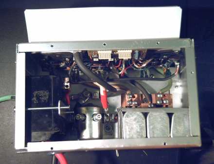
The new motor controller
10" tall x 6" wide x 4.5" deep.
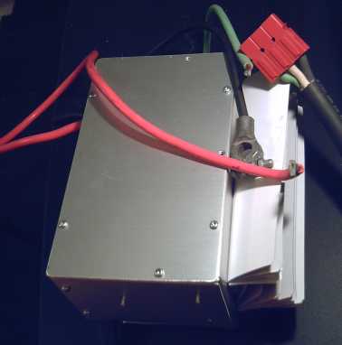
Totally enclosed wiring & electrical equipment
Laying out the several box mounted components (power switch or breaker, power "solenoid" relay, filter capacitors, heavy wire terminals) in the 10" x 8" box, it appeared the box could have been made as narrow as 5-1/2", say 6" for comfort, with good two-sides access. It's surprising how hard it is to find a convenient cranny in a car, near the wheel and big enough for the wiring/motor controller box, so size is important.
In fact, an eight inch width doesn't fit well where I want it to in my own car, so I cut the box down to 6" wide. It looked like everything would fit great, but I found the 200 amp breaker I chose for a main power switch didn't quite fit in front of the solenoid relay (which turns on the power from the car key) as I'd planned, and everything had to be rearranged. It all fit in the box, but not as happily as intended.
(I must look again for physically smaller breaker-switches. I know I saw some on the web at one point.) There are also high current battery switches for marine use, but they lack a safety circuit breaker function. With the breaker, at least if a screwdriver gets in and shorts the 36 volt bus to ground or something, it'll probably trip off before anything blows up.
On July 29th I finally had everything ready, including a couple of wooden "feet" for clamping the motor onto a workbench, and I tried it out at 12 volts. Bizarre things happened. Then I checked and found I hadn't rewired the control box with the switches and speed control for the new motor controller - I thought I had. Once that was done, everything worked flawlessly, to my great relief. And I could use the frequency meter to get the RPM! It's a big plus knowing the RPM.
Then I went up to 24 volts. Still worked great. The next day I got up the courage to try 36 volts. Still worked great! Phew!
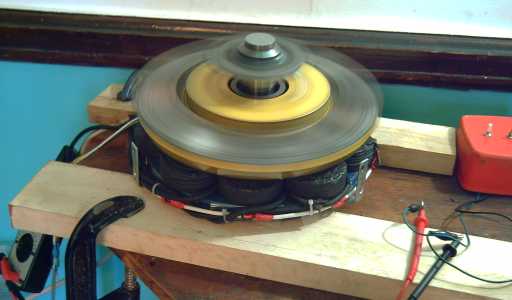
New controller running motor on bench
The motor seemed to use more power to turn the same speed as the voltage went up. There's probably some magnetic subtleties to check out here.
And I noticed the motor needed more power to go clockwise than counterclockwise. I thought I'd determined that the timing wasn't that critical!, but what else could it be but a timing issue? Then I tried spinning it by hand: sure enough, for some reason there was more actual friction turning it clockwise! (Perhaps I should grease those trailer bearings!)
| Volts (nominal) |
Amps turning CCW @ 620 RPM (no load) |
Watts CCW (V * A) |
Amps CW @ 620 RPM (no load) |
Watts CW (V * A) |
| 12 |
6.9 |
83 |
8.6 (580 RPM - maxed out) |
103 |
| 24 |
7.0 |
168 |
8.9 |
214 |
| 36 |
5.2 |
187 |
7.7 |
277 |
I also noticed that the motor ran more smoothly at the lower voltages. That was probably related to my uneven magnet spacings and the air gap, which was also uneven.
These things are all adjustable. They'll bear some testing out.
At 12 volts (being wound for 36) it would just hit 620 RPM going counterclockwise. At one point (with more volts) I turned it up to 1000 RPM. That was pretty scary -- an open, large diameter motor whirring away on a table in front of me. Bits picked up here and there by the magnets over time were flying off and hitting me. But the whirring magnets were fanning a good breeze, which is exactly what's needed for cooling the coils in real use. I didn't try to find out what full speed was at 24 or 36 volts.
Later I straightened the alignment and evened the gap around the rotor and tried it again. The final and a bit wider gap, silly though it may sound to anyone familiar with motors, was about 1/2 inch. The currents were somewhat lower for the same RPM speeds.
| Volts (nominal) |
Amps turning CCW @ 620 RPM (no load) |
Watts CCW (V * A) |
Amps CW @ 620 RPM (no load) |
Watts CW (V * A) |
| 12 |
6.5 |
78 |
8.3 (just makes it to 620 RPM) |
100 |
| 24 |
6.7 |
161 |
8.1 |
194 |
| 36 |
4.7 |
169 |
6.4 |
230 |
So! Comparing the two tables, the idling efficiency goes up with increased gap, and the lower the supply voltage the less energy it uses to idle at a given speed! I should try changing the PWM rate and see what difference it makes. I used a lower frequency than the chip maker recommended.
I may want to try some thinner supermagnets, eg 3/8" or 1/4". Then I can put on 18 evenly spaced for smoother operation and reduce the air gap. Or maybe I should just try evenly spacing 12 "normal" size magnets next time. (If only epoxy wasn't so hard to get off, I think I'd try redoing this rotor.)
Actually, the guy I've been ordering magnets from was down to his last few, and he sent me some 2" x 2" x 1/2" because he was short of 1" x 2" x 1/2". The next rotor may just have six of those! and it'll probably run smoother than this one.
Then I checked at 1000 RPM. E = 1/2 mv2, and 1000 RPM2 / 620 RPM2 = 2.6, so that's almost three times the rotational energy, but it took only somewhat more watts to keep it spinning than 620 RPM:
| Volts (nominal) |
Amps turning CCW @ 1000 RPM (no load) |
Watts CCW (V * A) |
| 24 |
8.4 |
202 |
| 36 |
7.3 |
263 |
Of course, all this is just the idling motor. A more pertinent question is how it does with a heavy load, and I still have no ready means of testing that except to get it to run the car.
I found a "bug" in the motor controller chip: if you flip the direction switch while the motor is still turning, it comes to a grinding halt even if no thrust is being asked for from the PWM control pot. It probably deliberately turns on all the low side MOSFETs at once, shorting all three wires together. This "instant stop" "feature", which isn't even mentioned in the datasheets, will prevent regenerative braking!, which is accomplished by telling the motor to run backwards to the direction it's going -- precisely the condition where the chip internally shorts everything out. I had planned that regenerative braking could be added later by a fairly simple external control circuit.
It's probably pointless now, but perhaps later if the Electric Hubcap is catching on, ON semiconductor could be approached and asked if they would do an ammended version of the MC33033 chip. In fact, at such a hypothetical time, perhaps they could be asked for a modified chip for the express purpose of powering 3-phase electric vehicle motors with regenerative braking, so that no external circuit would be required.
Magnetic Torque Converter Project:
Torque Leverage Without Gears
July Details
Torque Leverage Without Gears
July Details
I didn't have time for any actual fabrication work. I hope to concentrate on this project in August.
Microcrystalline Electromagnet Coil Cores
July Details
Again I've had an idea for something in a field I haven't worked in before. But if microcrystalline cores that carry enough flux density for motors can be made, they have potential advantages:
1. They're easier to make than spray painting, fitting together, and varnishing or casting. And they'd make the coils easier to wind. Easier and less manual labour ultimately reduces the cost of the motors.
2. They probably would have lower iron losses than laminates, in fact probably trivial losses, making the motors more efficient.
3. They're lighter - half the weight. This will save almost a kilogram per motor. (Of course, that's out of 20+ Kg. Still, trimming a bit here and there can add up.)
4. Cooling air flutes or holes could be cut or cast into them.
I was also hoping a successful finished formulation will transfer magnetic flux effectively but without itself being attracted to magnets. Non-cogging coils would have special implications, for example in windplant and other generators where it is important that the propeller or other driving force not be magnetically "stuck" in one place in a light breeze. My ocean wave powered generator would probably have worked if not for the cogging of the generator in it.
Of course there are also potential down sides:
1. They may be more fragile. That's why I'm using the porcelain-like clay and adding feldspar for strength. Like porcelain toilets, I expect they will prove to be "tough enough" for their intended use. (Two of the latest and best cores, just fired, fell off a table onto a wooden floor and didn't chip or break.)
2. They may saturate magnetically at a lower flux. If the available flux density is too low, the idea won't be viable for high power motors.
3. They are likely to have a lower flux density than iron even in working range, that is, to be much more effective than an air core but not as good as iron.
Items two and three could limit the power available from the motor. I'm still learning and experimenting, so the last word isn't in. If the best I can do is better than air but not good enough for high power motors, but is also minimally attracted to magnets, they could still improve (eg) air-core windplant generators, reducing the size, the number of supermagnets and the amount of copper wire required.
I made several test cores to compare, and I came up with a methodology of construction.
I should say at the top these procedures are just my current best conception (July 20th) of how to make them and what should go into them at this early period in the development and testing.
First, iron oxide, custer (potassium) feldspar, ilmenite and Laguna borate are mixed into the clay, as much "stuff" as it seems the clay can hold. The iron oxide should be ferrous (FeO), which seems to be the most magnetic, or magnetite (Fe3O4). Ferric oxide (Fe2O3- red rust) appears to be non-magnetic, or at least not attracted to magnets.
Boron is a flux, and the borate is used as a frit to lower the firing temperature of the clay. And, the Laguna borate (specifically Laguna) has aluminum (mentioned in connection with microcrystalline cores), iron and titanium oxides. I found out after making a few coils that cone 5 (~2150 F) is hot enough to destroy of modify some "dielectric" properties, doubtless also magnetic properties. Now I'm trying cone 05 and other lower temperatures, 1800-2000 F. Boron is also the third ingredient in "NIB" (Nd-Fe-B) supermagnets. The local pottery supply actually happens to have some neodymium oxide, too. But I'm not sure what either neodymium or boron might be good for magnetically, in electromagnets!
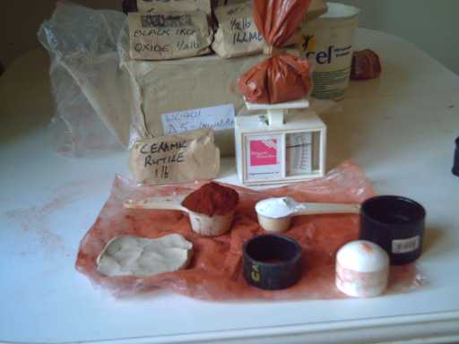
Materials of an early test core, all from the pottery supply store.
On the plastic is the clay, ferric oxide, feldspar, and the plastic mold pieces.
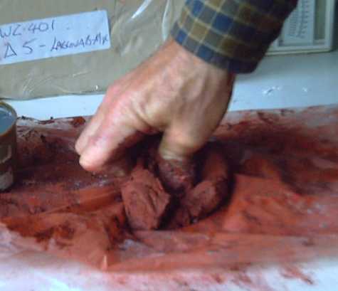
"Wedging" (mixing) the ingredients. Another reason not to use ferric oxide: It's really messy!
Careful as I was, and though I wiped and mopped, the table and floor are still reddish.
Then, the clay is pressed into the mold.
<
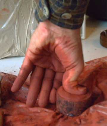
Then the two mounting bolt holes are "drilled" out by hand with a piece of 3/8" brass tube with "teeth" filed into one end. Each plug of clay is pushed out of the tube with a pencil. (A 1/2" tube might be better - the holes shrink during firing and again with each coat of glaze laminating.)
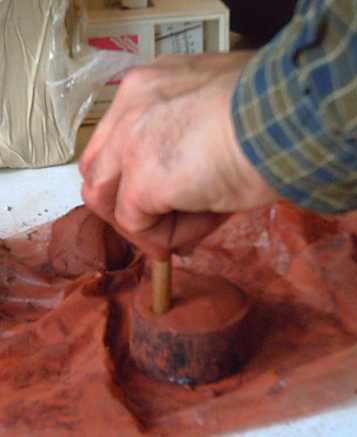
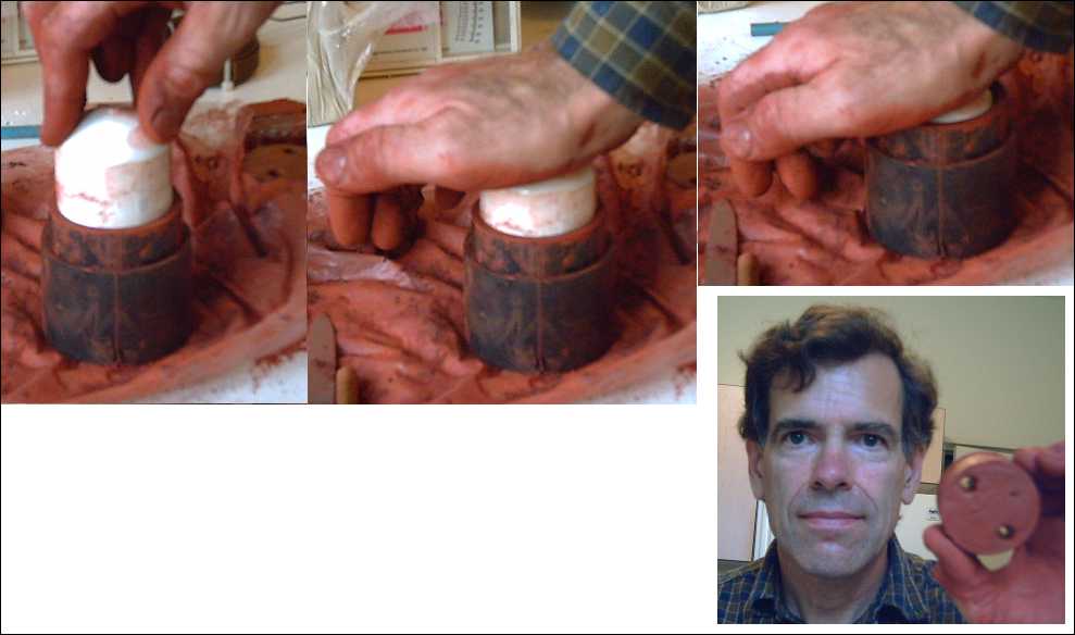
The mold, a 1.2" long piece of 2" ABS plumbing pipe, is placed into a pipe-joiner piece, and a pipe piece that just fits inside the mold piece is pressed down to eject the core evenly on all sides from the mold. (The 1.2" length allows for clay shrinkage, in drying and again in firing, to just over 1". The 2" diameter should be a little larger as well to end up with 2" coils.)
(The 200 grams of materials proved to be virtually enough to make two cores, so I did, using a leftover bit of rather similar clay from the previous coil to "top up" the second one.)
Then it's typical pottery procedure: dry it, dry it some more, eg, in the oven at 225 degrees (F), to drive out any remaining moisture so it won't explode in the kiln, then put it in the kiln and fire it to cone 5 (2150(?) Farenheit).
There you have the core of the core. If you had a pottery supply pre-mix the ingredients, and machines to squeeze the clay through an extruder mold, cutting the extruded clay into sections as it comes out, you could make hundreds of uniform motor coil cores in an hour and would need a bunch of dryers and kilns to process them all.
An interesting observation is that a raw core with ferric oxide (red rust) isn't attracted to a magnet, while a ferrous oxide (black powder) core is. However, after firing, neither core is attracted to the magnet.
Now the core is laminated with two layers of minerals with differing magnetic properties. The reason is to optimally direct the magnetic flux, emanating from the coil wire, into the core and out its top and bottom ends. The process is to dip it in mixes of sodium silicate (AKA "water glass") with the desired mineral powder. Sodium silicate hardens with heat by releasing its water at about water boiling temperature. Thus it forms a "glaze", glueing the powder in it onto the core. (Think of raw egg white - it starts wet, but if it dries onto something, it's hard stuff to scrape off.)
First you dip the core in sodium silicate with ilmenite powder mixed into it. Ilmenite is a mineral composed of blended iron and titanium oxides. That provides a coating or layer with ferromagnetic and paramagnetic properties, titanium being paramagnetic.
Paramagnetic materials will line up, magnetize, in the presence of a magnetic field, but as soon as the external field is removed, the crystals (or was it some sub-crystalline unit? No matter!) re-orient randomly, losing their magnetism.
This is placed in an oven at about 250 (F) degrees for a few minutes (15?) to set the sodium silicate. There's no smoke or fumes. When sodium silicate is heated above the boiling point of water, it hardens, casting the layer in place. Thus you have the core, glazed with ilmenite "icing".
Next dip is a coating of Rutile (again, in sodium silicate), preferably "Niobic Rutile". Rutile is a mineral, mostly titanium oxide, with iron, niobium and tantalum oxides as frequent "significant impurities". Niobium is strongly paramagnetic and in superconducting has "the greatest magnetic penetration depth of any element". Tantalum is the element below it and has similar properties. I can't find any specifically "niobic rutile" for sale on the web, so the titanium and whatever happens to be in what I buy at Victoria Clay Arts will have to do.
Now the coil wire is wound right on the core. (For this I'll need to make a new coil winder designed for this direct wrapping method.) Since the skin of the core is fairly smooth and electrically non-conductive, there's no need to insulate or protect the wire.
Another dip in rutile, after heating, sets the coil wire in place on the core, thus replacing motor varnish or epoxy. (Tooo clean and simple!) The paramagnetic rutile and the mixed magnetic ilemite help carry the magnetic field from the coil wires into the microcrystalline core.
Now, if only the price of copper wire hadn't doubled in the last 3 years, we may, hopefully, be on the way to cheaper motor coils as well as better!
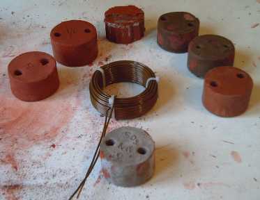
First Test Coil Cores
Center: Test coil
12 o'clock: original nail gun finishing nails core
1: 12.5% ferric oxide with thin ilmenite coating. Some has chipped off - perhaps it doesn't adhere to finger grease?
2: 12.5% ferrous oxide with a rather thick ilmenite coating. (This was the first one, then I thinned the mix.)
3: 50-50 mix of ferric and ferrous with clear sodium silicate "glaze".
6: 25% ferrous oxide.
10: 28.6% ferric oxide
11: 37.5% ferric
First Test Results
The laminate (nail gun finishing nails) core repelled (lifted or moved the magnet) at the greatest distance, 1-13/16". The ones with 12.5% iron oxide weren't much better than air core, 1-3/8" to 1-1/2". The one with 25% FeO seemed better, 1-5/8". There were too many vague things in the tests to be precise, and the outstanding conclusions were (a) that adding more oxide seemed to be necessary and helpful, and (b) that a better test setup, precisely repeatable and that would provide actual numeric measurements for comparison, was required.
As a result, the next cores have much more ferric oxide crammed into them, up to 37.5% by weight. Volume-wise, the pile of rust powder looks bigger than the piece of clay. They make for very sandy, gritty feeling clays. But I'll try 50% next...
That's a good thing to remember when the electric lawnmower is "bogging down" using a long, light cord, too!
On the next firing, I plugged in in the kitchen, but the voltage was still only 112. It reached cone 5, but it took 3-1/2 hours.