Someone pointed me to a very similar hybridizing concept to the Electric Hubcap system. In fact, it's almost identical, axial flux and all, to my concept without the magnetic torque converter:
http://www.poulsenhybrid.com/
It looks like they plan to keep the gas engine running and use the electric motors to save gas, struggling with the same issues of the motors not having quite enough torque to accelerate the car practically by themselves. The torque converter is the key to being able to run without the gas engine turned on.
The most remarkable thing to me is that I hadn't run across this design before!
The design for the Electric Hubcap motor and the updated design for the Turquoise Motor Controller are on the web.
Magnetic Torque Converter Project:
Torque Leverage Without Gears
July Details
Torque Leverage Without Gears
July Details
I had hoped to concentrate on this project in August, but somehow I found myself drifting into battery and microcrystalline coil cores experiments.
I did, however, come up with a new design with an entirely different operating principle. It should be very efficient as well as effective, so perhaps it's just as well I didn't get any farther.
Here's the basic idea I have worked out, as currently envisioned:
* The motor is axial flux, so the supermagnets face the stator crosswise, on one face of the rotor. (which is a car disk brake rotor.)
* Another set of supermagnets is glued to the opposite face of the rotor for the torque converter. This provides a supermagnet strength rotating magnetic field. The motor rotor does double duty, as it's also the input rotor of the magnetic torque converter. (Of course, a separate rotor would work too.)
* The aluminum output rotor is a "frying pan" or "bowl" shape. It's bolted to the car wheel (or drive shaft, or other load).
* Supermagnets are attached to the rim on hinges. They are free to swivel from 45 degrees away (with one end touching the back of the frying pan) to 0, flush with the back side magnets on the motor rotor, with a small air gap. (I plan to put an aluminum plate ring around the top of the frying pan for them to hit against, as the attraction between supermagnets is very powerful.)
* When the magnets fold back to 45 degrees, they contact a small piece of steel that latches them there magnetically. (Some on the bottom or top may be retracted by gravity, and if the wheel is turning very fast, they may also be held centrifugally - all depending on the pivot balances in the exact layout used.)
* In operation, the motor turns. When a like polarity magnet face reaches the pivoting magnet, it pushes it away, and it folds back and latches against the steel piece. No significant turning force is generated.
* When an opposite polarity magnet approaches the retracted pivoting magnet, nothing happens until they are almost directly across from each other. At that exact point the attraction between them overcomes the attraction to the steel latch and the magnet jumps forward next to the magnet going by, with a small gap.
* If the two magnets were simply fixed to the rotors, the output rotor would have been pulled backwards as the attracting magnet approached and then forward as it receded. The forces would have canceled and there would have been no net torque.
* However, the output magnet is folded away as the motor magnet approaches, so the output rotor isn't pulled backwards. But then it jumps out, and as the motor magnet recedes, it is very strongly pulled forward. Thus there's a strong pulse of forward torque with no equal pulse of backwards torque.
* At the crossing of the two magnets, the motor, while yanking the wheel forward, is itself slowed. Between magnetic "hits", it has time to recover its speed.
The best number and spacings of magnets on both rotors, the strength and setup of the magnetic latches (or retraction springs), and matters of hingeing, angles and orientations, air gap and so on are matters of trial and adjustment to create a good embodiment within the scope of the invention.
With the 10 magnets on the motor rotor backside, it's 72 degrees between any two like magnet poles and 5 magnetic pulses per revolution passing any given point.
I estimate that the main pulse of magnetic force is spread over about 12 degrees. Thus, considering one output magnet and with the output rotor stopped, the motor is slowed by providing a powerful turning torque for 12/72 or 1/6 of the time, and it has 5/6 of the time to recover its speed. Additional output rotor magnets will spread out the pulses and smooth the operation. With 6 output magnets, there would be 30 pulses per revolution.
The gap between rotors will have to be adjusted so that the motor will reliably start if stopped at any one magnet, and any additional gap necessary for smooth operation. This is the limitation to the maximum coupling and force that can be applied for each output magnet. To have more maximum force, more output magnets are required.
It seems to me that the stopped output rotor should have almost 6 times the torque the input rotor - the motor - is capable of delivering by itself. One Electric Hubcap motor will thus provide the torque of six to get the car rolling. As the speed of the rotor approaches the motor speed, the torque drops off until, if the torque required is small enough, two magnets "lock" opposite to each other and both rotors turn the same speed with one-to-one torque.
Right now I'm working out pivoting mountings for the magnets and other hardware, that I hope can take the strong forces involved.
Microcrystalline Electromagnet Coil Cores
August Details
In Wikipedia I find the following definition:
"Superparamagnetism is a form of magnetism. A superparamagnetic material is composed of small Ferromagnetic clusters (e.g. Crystallites), but where the clusters are so small that they can randomly flip direction under thermal fluctuations. As a result, the material as a whole is not magnetized except in an externally applied magnetic field (in that respect, it is like paramagnetism)."
Here is the essence: rather than either "normal" iron crystals or paramagnetic elements, the main ingredient for a strong flux carrier with virtually no magnetic hysteresis is microcrystalline structured iron.
I tried 3 more cores with Fe3O4, FeO and slightly different compositions, and baked them to the lowest temperature yet, with a charcoal briquette in the kiln to create a reducing atmosphere. Then I quenched 2 of them in hot water and let the other one cool slowly.
The charcoal briquette, glowing but still solid, went in the woodstove. The idea of using charcoal to create a reducing atmosphere puzzled me until I actually tried it myself: wouldn't it just burn up in no time and then be useless? But of course!: it's used up all the oxygen - that's the whole idea - so tho it glows red hot (along with everything else in the kiln), it only burns up as fast as more oxygen enters the kiln!
None of the cores worked at all. With no results, I decided to put the project on hold, as it isn't one of the key objectives anyway.
Then I joined an inductor making discussion list, where I was advised to read about magnetically "hard" and "soft" ferrites. Sometime in the reading, I finally realized iron was iron: not ferrous oxide, magnetite, ferrite or ferric oxide, just iron powder. The usual main ingredient of motor coil cores I hadn't tried adding at all!
I decided to try steel grindings. I collected a whole salmon tin of grindings with a magnet from around my bench grinder, which it seems I fortuitously hadn't cleaned around in ages. However, this core appears to be no more successful than the others.
Now I find that in addition to "ferromagnetic" there's "ferroelectric" materials - related but not necessarily including iron in the mix at all, for instance barium titanate. Barium titanate can be produced by mixing barium carbonate with titanium dioxide wet in correct proportion, drying, and then heating to 900 - 1200 degrees C. The barium carbonate melts (actually, it probably calcines) at 811 C.
I definitely need to read further.
August Details
A Battery Reference Book!
Wow, I found a technical book on batteries! I was looking over an obscure patent and it quoted the book as a source. I went to the library and got it on an inter-library loan (all the way from Queen's Dupuis Hall Library).
The book, Alkaline Storage Batteries by Falk and Salkind (1969), was a gold mine of information. However few copies may exist, it's widely quoted in later patents and appears as far as I can tell to be the only definitive reference work on the subject (aside from a 1920 write-up of nickel-iron batteries by one of Edison's engineers). A bit dated but a must read for anyone making batteries! Aside from a few upgrades like spot welding and plastics, it was surprising how little "pocket batteries" had changed by 1969 from Edison's 1908 designs.
No wonder I can't seem to get a consistent story on electrode reactions off the internet: it seems they actually aren't (as of 1969) too well understood, and the book gives conjectures for some common reactions as to just what is really going on, saying Mr. X says "this", but Mr. Y thinks it's really "that", with "the other thing" as an intermediate product.
I also note there's "formation cycles" when a big "pocket electrodes" battery is first made. Electrodes are placed in baths of electrolyte before installing in batteries. One interesting result is that impurities in the electrode material dissolve out in these initial charges. These are discarded with the used electrolyte. I'm not sure just how this could be accomplished in a sealed battery. (I've put in a 1/4" bottom spacer so that anything that wants to precipitate out has somewhere to go.)
Well, much the best electrode so far has been a perforated tube that I rammed nickel hydroxide and fine monel powder into. With about 50% monel by weight - but presumably under 25% by volume - it had a very low dry resistance, just tens of ohms as measured on an ohm meter from "anywhere inside" to the collector plate. The potential was there for extremely high currents.
However, the electrode swelled, pushing stuff out the holes, and the conductance went way down. Still "okay", but now not "amazing"! I surmise the NiOOH is even bulkier than the Ni(OH)2 so it needs more room as the battery charges, so it pushed the grains of monel apart and they lost contact with each other. (The book mentions that Ni(OH)2 pocket electrodes swell. Also alpha NiOOH is even less dense than beta if you manage to get extra valence change - swelling from that could be theoretically up to 44%, by which point I suppose you'd have NiOO. No one has got the valence above 3.8.)
This is of course a problem with the nickel hydroxide reactions, not the electrode design, suggesting it would be nice to find some other positive electrode chemical for physical as well as chemical considerations.
At first I decided to capitalize on the tube idea. The first tube only had dozens of holes, labouriously punched and drilled with a tiny drill bit that, predictably, finally broke. This time I bought a perforated brass sheet at the hobby shop with about 7 x 8 = 56 tiny holes per sq.cm, and cut a 3" x 3" piece. This I nickel plated (ug!), then bent a hook onto opposite edges, and bent it around into a cylinder with a locking seam. I finished by soldering a 3" nickel-brass #8 leed wire on with silver solder, and I went over the solder and the edge bends again with the nickel plating brush. I cut a tapered plastic bottom plug. (top plug,? later!)
Into that perforated cylinder I planned to cram some previously made lanthanum hydroxide mixed with monel and fired in thiamin mononitrate (tinned bean sauce) for a positive electrode.
Instead of a matching negative electrode in another perforated tube, this battery was to have two concentric electrodes. The outer perforated surface would be the inner surface of the outer electrode (with a separator of course), creating a good interface.
Cylinder battery pieces
If this could supply a good figure like 100 or 250 mA/sq.cm of interface area continuous, that would be about 5 or 12 amps from a battery of simple construction not much bigger than a "D" cell. Make it 30 cm tall instead of 7 and that would become 20 or 50 amps. Then three wide for 150 amps times maybe 20 batteries for 36 volts would be 60 tubes powering an electric car. 15" x 10" x 13" tall. Without going into detail, maybe 3-4 KWH, 20-30 Km range. There's a potential.
I cut a 3" x 4" piece of nickel-brass as an outside "can" cylinder surrounding the perforated one. I soldered on a similar leed wire and nickel plated the solder. (Normally these things are done with spot welds, since you don't want a join that will corrode off or leach contaminants into the battery. I don't have the equipment.) After putting in a separator sheet painted with zirconium silicate powder for an ion shield, I planned to cram manganese hydroxide powder (and monel if the conductivity isn't high) into the space between the inner electrode and the outer "can".
The separator sheet must take the pressure and abuse without letting the two electrodes connect. The outer "can" wasn't to be soldered at the seam and would have no bottom, so the battery will be in a transparent plexiglass tube. (As I think about this, the transparent tube wouldn't reveal very much with a piece of sheet metal covering most of it.)
That was the plan for the finished battery. However, I planned to try out a couple of perforated tube negative electrodes, and the nickel and the lanthanum positives, with electrode tube pairs immersed in a bigger tank of electrolyte for test batteries. I may still do this. These won't have the current capacity of the concentric electrodes, but they should be good to test electrochemistries and measure battery voltages.
But I couldn't help but think a square shape would be better than cylinders... but how to compact the electrodes... and keep them that way?
The answer to "keeping" may lie in really tough separator sheets where the electrode can be somewhat compressed against the sheet in use and all the electrodes sandwiched into a rectangular box.
But what about powerful high pressure presses for compacting them in the first place?
Following up on the thoughts above about square batteries, over my holiday I decided to abandon the cylinder without even trying it, at least for now, and to try making a system for doing flat plates. For one thing, in spite of electroplating, the perforated brass sheet still looks yellowish. I have little doubt it will quickly corrode like the first one did.
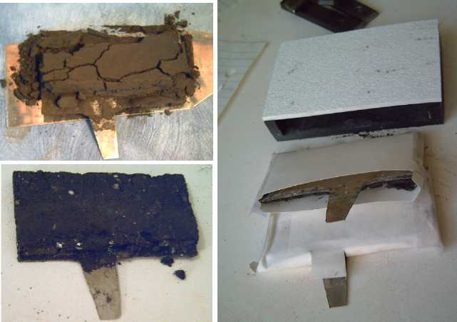
I realized flat electrodes could be compacted about the same way as the perforated tubes if they were placed in a steel box with an END open instead of a FACE: from one end with a plunger rod and a hammer. (I may or may not have written of this idea before.) The trick is not to damage the the stainless steel mesh on the collector plate in the process.
I decided to use the previously shown rectangular case (right, below), but after seeing the book, I would put it on end, with a small gap - 1/4" or 1/2" - at the top, and another small gap at the bottom to hold any sediments that precipitate out. The electrode terminals would stick out the top at the sides, with a pressure relief valve/filler cap in the middle.
L to R:
Steel box bottom & sides (note beveled top end)
a 3" x 12" electrode collector plate, wrapped with stainless steel mesh
box top (bolts through sides to bottom)
"ideal" final battery case (will stand upright)
I took two flat plates of steel (1/4" thick) and three pieces of steel bar, 1/4" x 1/2", and made a very strong, stiff box that bolts together. Inner dimensions are 3" x 12.5" x 7mm. The flat plate electrodes with stainless steel mesh (left of center) as previously planned are to be 3" x 12".
The 1/4" thick bar gives about ~7mm thick electrodes. Another set of bars 3/16" x 1/2" gives thinner electrodes (~5mm). Only one end of the box is open, a 1/4" x 3" opening. I ground off the edges at this end at an angle to form a bit of a funnel to pour electrode powders into the box.
The electrode compacting ("loading", "briquetteing") procedure is:
1. Cut a sheet of plastic (eg mylar, acetate...) to the outer size of the box.
2. Bolt the box together with the plastic covering one inside face.
3. Slip in the electrode plate opposite the plastic, stainless mesh facing in, leed sticking out the open top.
4. Put in a couple of temporary plastic wedge spacers to hold the electrode plate against the side.
5. Pour in some electrode mixture.
6. Tamp it down using a steel bar that's thinner than the space and beveled at the end so it won't easily rip the plastic or mesh. Pound it with a hammer. (If the mixture is too wet, it may ooze around the sides instead of compacting. Get it drier and try again.)
7. Repeat 5 & 6 until full, removing the spacers whenever convenient.
8. Unscrew the box bolts, take the top off and peel off the plastic.
9. Twist the sides and bottom end piece loose (if they stick to the electrode) and remove them. (I should probably polish the side pieces.)
You should now have a solid - tho easily crumbled - electrode sitting on a piece of steel. The texture and stiffness will depend on the formulation (that's another subject) as well as on how hard you hammered down each layer. I note that the battery book calls bars of compacted active material "briquettes".
11. Wrap it in an envelope of separator paper/material.
To try out electrode formulations, I made electrodes just 3" x 1.5" instead of 3" x 12". I filled 10.5" of the box with a wooden filler piece and worked up by the open end.
The negative electrode was a mixture of manganese hydroxide [Mn(OH)2, 23.4g] and potassium permanganate [KMnO4, 10.0g]. To this was added a bit of Sunlight dishsoap and a little acetal ester as gel. On the second try it made an electrode about 77 x 35 x 5mm, giving 27 sq.cm interface area and 13.5 cc volume.
For the positive, I used 25g of the previously burned monel powder/La(OH)3/bean sauce/Sunlight mix plus 12.5g of straight La(OH)3, again adding a little acetal ester for "polyester" gel. This electrode had the same dimensions but was about 7mm thick.
I confess I haven't worked out the amp-hours for these mixtures (it should be a few AH), and the voltages are unknown except that manganese hydroxide to manganese is -1.56 volts in alkali solution, which I used. The battery could be as much as three volts, which means I should have used the "voltage ramp" stuff. 27 sc of interface surface is only 3/5 of the surface area of the rolled up Ni-MH "AA" cell I cut open, so the max amps won't be too high.
Mn Electrode as first made.
Crumbled Mn electrode after drying. This was redone later, with the electrode mix dryer and harder hammering. That seemed to hold together. Below, La electrode "briquette". Stuffing electrodes wrapped in "Arches" watercolor paper into the case. The inside of the Mn electrode envelope is painted with zircon. The leeds are part of the electrode plates, so there's no solder, welds or bolts. But I found sealing the case with such leeds coming through virtually impossible except by clamping them with C-clamps.
After charging the battery a few days with the top not sealed, I took it apart. I inspected the Mn electrode: it had a hard, lighter coloured crust on the face where it was against the other and in contact with the ZrO2:SiO2 (AKA zircon, zirconium silicate or pottery trade name Ultrox).
So, what's still missing for good working batteries?
* Leeds need to be welded or bolted to the collector plates. (These batteries are "lead free" but have "leeds"!) Soldering, even silver soldering, probably won't last because the metals used for the solder will corrode away in the salt and-or with the battery charging/discharging reactions. Welding is doubtless the best, but I don't know how to do that sort of miniature spot welding. Small, very short, stainless steel bolts, however, will be of service at least for prototyping.
* Then, it'll need the pressure relief valve/fill cap. I found a screw-in adjustable pressure relief valve at Coast Industrial Parts. (On order.) The "cap" will have to be unscrewing the whole valve. I also got a pressure reading dial to get an idea how much pressure builds up.
* The separator sheets have yet to be formulated. I'm asking a lot from these - ion shielding, voltage ramping, very good wet strength, and longevity.
* Actual working electrode formulations with high conductance that will work and continue to work in a salt electrolyte that may be mildly acidic, neutral or mildly basic. (Pick one!) The pH aspect of the electrolyte in turn depends on what works well with the chosen electrode chemicals.
I'm not content with a nickel hydroxide positive unless it gives a volt instead of 1/2 a volt -- which it may do in a neutral to acidic electrolyte instead of alkali -- and better amp-hours than the typical less than a single change of valence state. (which it has been enticed to do by some lately, obtaining valence 2.2 discharged to 3.8 charged: a change of 1.6.) There is probably some cheaper and maybe better alternative - nickel has been going up and up in price.
Zinc oxide or hydroxide has been used to better effect recently for negatives, the branching dendrite problem being reduced or eliminated, but I'm trying manganese [eg Mn(OH)2 + 2e- <==> Mn + 2OH-], an enticing looking reaction probably about -1 volts in a more neutral pH battery.
Round pipe is a poor shape for flat electrodes, but the seams along the whole length at each corner on the rectangular case continued to disturb me. I've finally learned that to get a good seam, it should be C-clamped along its entire length while the solvent/glue dries. But surely even so, wouldn't such long seams still be a source of trouble?
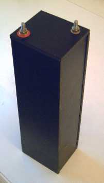
The 3" x 12" x whatever thickness, concept battery case. (A new feature is stainless steel bolts for terminals. The smooth heads are tightened against the smooth plastic inside of the case, with a leed or the actual edge of the collector plate welded to them. I think these won't leak.)
I looked on the internet for seamless rectangular tube, but searching for merchandise has been made enormously difficult by dozens of "linking" sites all claiming they have what you want - whatever it is - but they only point to a zillion real businesses that are mostly irrelevant to what you searched for, while the handful of real makers of what you want, that should have turned up near the top of your original search results, are hopelessly lost amidst hundreds of these bogus "hits" - links to links to links to irrelevance and a waste of time.
In one experiment quite a while back, I heated some ABS plastic and found it could be bent and would retain the shape when it cooled. It seemed hopeless to try to bend a big piece with the heat gun, but a new plan dawned on me: I could heat foot long battery lengths of 3" ABS plumbing pipe in the oven, and jigs and formers would make it roughly rectangular with rounded corners, or at least oval. Not perfect, but it would be just about the right size to make into batteries with four electrode pairs. No seams!
Then all it would need is the ends sanded perfectly flat, and the flat top (with the fittings and electrodes) and a flat bottom glued on.
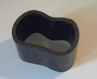
First try at making a 3" round ABS plumbing pipe rectangular in the oven.
(It was just a rough test jig!)
When I started out and found the reaction voltage of lanthanum to lanthanum hydroxide was -2.9 volts, I thought "Wow, what a great voltage, why hasn't anyone done this? Why are they all using iron, cadmium or metal hydrides that are under one volt?" Then I found out that water starts to electrolyze at about 1.23 volts, so everyone was looking for lower voltages. However, it was said to electrolyze quite slowly up to about 2.0 volts, so we have, for example, one of the reactions of lead-acid being 1.7 volts with a total of 2.1 volts. If the charging voltage goes up to about 2.36 volts (iirc) per cell, the water starts bubbling vigorously, and the gasses are vented to the air. (The 1.7 volt side probably hits the 2.0 volt limit.)
But: These cells are vented, essentially unsealed. So are all the other big batteries. What happens if a higher voltage cell is sealed? Nothing is said about the idea in the battery book. One patent mentions the challenge of high pressures involved with Ni-Zn "AA" batteries because of their higher charging voltages, although they are under 2 volts.
At first of course, the gasses start to be given off. That raises the pressure. Thermally, we know that the boiling point rises with air pressure, so what about electrically? Will the gasses continue to bubble off at the same rate ad infinitum until the cell, however strongly built, leaks or bursts, or will high pressure raise the voltage the water bubbles at until at some finite pressure it stops gassing at the given voltage? Alternatively, might the high pressure gasses, H2 and O2, start to recombine into water as fast as they're being generated?
I didn't find satisfactory or definitive answers to these questions on the web. I also didn't know what pressure range to expect. (15 PSI? 30? 60? 120?) Perhaps the only way to be sure is to create a battery that doesn't leak under pressure and see what happens. I strongly suspect that a pressurized battery is the key to permitting these higher voltage reactions and hence attaining higher energy density in an aqueous battery. (and goodbye to pricey lithiums!)
To test the theory, I simply reversed the charge on my present La-Mn cell, making it Mn(+)-La(-), and if it doesn't leak and the -2.9 volts reaction works, it should charge up (with the manganese oxidation reaction at a whopping +0.15 v) to 3.05 volts! Thus the emphasis on sealed cells: this can't work if they're not sealed, but it might if they are.
However, the attempts to create one so far have been pretty unsuccessful. This cell keeps springing leaks, and it now has 3 C-clamps helping to hold it together.
The theory appears to have merit. The cell was up to 1.77 volts at one point (26th. and it should charge very gradually the first time -- it's the "formation" charge), and every time it leaked, it lost a little voltage, even with the charge still on. I presume the pressure is gradually increasing with the voltage, otherwise why would it keep springing more leaks once it's sealed (again)? I've purchased a dial pressure gauge, and belatedly (28th) put it onto this battery. (And its fitting is brass, which will corrode... and leak!)
On the 29th, after yet more leak repairs on the 28th, teflon tape on the meter base threads, and four C-clamps holding it together, the cell finally held pressure, and hit 1.9 volts and 8 PSI. It'll be a few more days before it finishes "forming" and charges up the lanthanum and manganese.
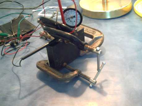
Several repairs and 4 C-clamps later (then 5):
No leaks, holds pressure!
Having such a high energy potential (-2.9v), lanthanum metal does spontaneously turn into lanthanum hydroxide in water (outgassing hydrogen). That would gradually self-discharge the battery, but the process is very slow in cold water: at least days, more probably weeks, maybe months. (It would have taken years to convert my lanthanum ingots into the hydroxide whole and in cold water instead of sliced up and in a hot pressure cooker - it still took weeks.) If it works, we'd have a very high energy density battery for daily driving, but not one to run a clock or smoke detector, or to turn on a flashlight when there's a power failure 6 months after it was last charged. Making the battery a "dry cell" might also reduce the self discharge.
Several times I have tried to use cellophane, which is said to be a very good electrode separator membrane, but it didn't seem to work at all. In the battery book, I noted the term "silver treated cellophane", and I looked it up on the web. In so doing, I ran across this revealing paragraph from someone making what sounded like "microfiche" film from cellophane:
"3. Preparation of the Cellophane: Commercial cellophane, such as is used for wrapping packages, is coated with a plastic resin to make it non-porous. Uncoated cellophane is available from chemical supply houses, which sell it as dialysis tubing or dialysis membrane. In all that follows we will assume that you have only coated cellophane available. The coating must be removed from one surface of the cellophane. Using a wad of cotton moistened with lighter fluid, rub the surface of the cellophane briskly. Turn the cotton over, remoisten and repeat. Hold the cellophane up to the light. The area you have rubbed should appear duller than the rest. Repeat the process using a fresh piece of cotton to make sure. From now on, handle the cellophane with tweezers or wear lint-free lab gloves."
I bought my cellophane at a crafts shop. It was called "Clearphane" and there was no composition info on the package. But I'd lay good odds it's actually plastic coated -- small wonder it doesn't work! I've been concerned about the possibility all along, but now I know something I can do about it -- assuming lighter fluid is still available these days.
The problem with making a salt electrolyte battery is that some of the reaction products are usually soluble in water, eg zinc chloride with a zinc electrode. Treated cellophane is evidently a key to making such batteries owing to its salt rejection, keeping the zinc ions of their own side of the separator sheet.
The salt rejection properties of cellophanes are substantially increased, and permeation rates decreased, by pretreatment with certain metal ions or presence of these ions at low concentration in feed solutions. In a typical case, a cellophane which initially rejected about 20% of salt from a 0.05M NaCl solution rejected over 70% in Presence of 10-3M ThCl4. Permeation rates were decreased, usually by a factor of 2 or 3. Additives found to have a marked effect were Fe(III), Th(IV), U(VI), Cu(II), and hydrolyzed Pb(II). Mg(II), Ba(II), La(III), and unhydrolyzed Pb(II) had little effect. The mechanism by which the additives affect the cellophane is not clear."
Fe(III) is of course the key ingredient of the red rust I've been smearing on. I suspect Os(VIII) is probably better than any of the above.
Of course, neither the cellophane nor any of these enhancements had any chance to work when the cellophane has been deliberately contaminated with plastic, with no mention of that fact on the package!
In an internet discussion list on August 31st, someone reported emptying the sulfuric acid from "spent" lead-acid batteries and refilling them instead with alum solution. (10 oz weight of alum per 40 fluid oz distilled water)
He claimed that after a few charges the capacity comes back, and that they seem to be good for even more current than originally! He said he hasn't bought a new battery in 20 years!
It sounded incredible, but chemically seemed plausible. I thought I'd verify it by trying it myself, but then I searched and immediately found a blog with many entries discussing it. It appears it's true, and that many people have done it, also with epsom salt, and also even with brand new batteries:
http://blog.hasslberger.com/2007/01/how_to_convert_a_lead_acid_bat.html
As far as I can tell the idea was thought up by a Chinese person (a Chinese looking name on one web site), who patented it. It would seem the patent must have expired, perhaps long since, from the writer's "20 years" statement. It seems almost incredible that this hasn't become common knowledge. The many, many little-known valuable things like this, often of a medical treatment nature, disclose a great communication weakness within our society: we are virtually unable to disseminate valuable information to the public unless someone stands to make money from it.
In fact, it seems that at least two sulfate salts - alum and epsom salt - work better than sulfuric acid.
Compare:
H2SO4 (sulfuric acid: hydrogen-sulfate, ?)
NaAl(SO4)2 (alum: sodium-aluminum-sulfate, 35?)
KAl(SO4)2 (potassium alum: potassium-aluminum-sulfate, pH "mildly acidic", 9.5)
MgSO4 (epsom salt: magnesium-sulfate, pH 5.5-6.5, 33.7)
...All acidic sulfates, so like chemistries. Except one is horribly acidic and the others only mildly acidic. Of course, the renewed battery becomes much safer - a spill won't blind you or eat your skin and flesh.
The numbers at the end are the solubility in grams per liter of water.
I intend to try sodium sulfate. The molecular weight is a bit higher than magnesium, but the solubility is good and the sodium ions probably won't be as strongly bound to the sulfate as magnesium or aluminum, giving higher current capacity. Higher current capacity in turn means not only more engine starting capacity from a smaller battery but substantially better amp-hour performance at the moderately high current draw rates required for electric driving. Furthermore, it's highly unlikely the idea has ever been patented.
Then, since using a salt reputedly "restores" old batteries, it seems likely that the recommended maximum depth of discharge can be increased from 50-60% to 70 or 80%.
Overall it seems likely we'll see the useful driving range available to cars using common "lead-acid" (more accurately Pb-PbO/sulfate) based batteries extended over 50%, and the life span of the batteries tripled or quadrupled. Suddenly electric driving with common lead batteries looks far more economical!
Na2SO4 (glaubers salt: sodium-sulfate, pH 7, 19.5)
NaHSO4 (sodium bisulfate, pH 1.4, ~~70)
With a pH of 7 (neutral), Glaubers salt by itself may possibly not work. The bisulfate, which is the most soluble of any of these substances and more than acidic enough, can be made by mixing the salt with sulfuric acid (or NaOH + H2SO4), and although the pH of a one mole/liter solution is 1.4, Wikipedia says it's used in foods. Or perhaps just a little acid added to the mix would activate it. I've ordered the salt and I hope to receive it and try it out this month (September).
Although lead-acid batteries have lousy energy density and aren't the aim of my work, doubling (or better) their life span and improving their effective range would be very immediately valuable to electric transportation.
Evidently there's been no effective experimentation with the electrolyte since Gaston Plante invented lead-acid batteries in 1859 until rather recently, and this great info isn't spreading well! (Our society seems to have no means of spreading valuable general info unless somebody can make money off it.)
I've decided to try it out for myself. On September 1st I went in search of alum but found only epsom salts - 2Kg for $3.77 at Walmart. That's the cheapest battery chemical I've ever bought! (This was before I found the blog -- I was just guessing that epsom salts should work if alum did.)
http://www.turquoiseenergy.com
Victoria BC