By November I "smelled blood" and went rather single-mindedly at the mechanical torque multiplier. Naturally I think mine is the simplest and best design, but it has been a challenge to put one together at home from accessible materials that (I hope) won't quickly fall apart handling the forces needed to propel a car.
However, re-doing the assembly posed a number of small problems that conspired to delay getting the motor running and doing bench testing until the 30th.
The first couple of tests revealed that as planned, holding the torque multiplier rotor stopped by hand (with leather gloves on) became impossible as the motor speed and power were increased, and it seemed that a car on level ground would surely have started moving, with plenty of "throttle" remaining. Furthermore, the unit showed no sign of falling apart.
The next step is the road test. I'm now out in the cold rewiring the car. All the operator controls and connectors were modified with the new (MC33033 chip) version of the motor controller, and the motor power line's socket had to be changed to the APP connector.
When people hear "torque converter", they immediately assume it must be closely akin to the hydraulic crap, so I've changed the name to "Torque Multiplier" to make a conceptual distinction.
The inefficient, heavy and worthless hydraulic torque converter that the automakers have been fobbing off on the public all these years can only (very roughly) double torque. A lighter mechanical (or magnetic?) one can multiply torque by some tens, and efficiently - an automatic, varying, optimum gear ratio that replaces an entire transmission.
The Electric Hubcap system will be more than just a technical breakthrough: it's a relatively simple add-on to any car, with components that can be made separately or together in small shops, and I've created it as "open technology". It doesn't need the participation of Detroit (controlled by the oil companies), and there are no patents to be bought up to kill it. These facts can lead to a very rapid adoption of the technology. If we can sell the "whole kit" in one piece here, that will speed things up and greatly benefit Canada and BC.
I realized on the 25th that even the Minister of Finance wouldn't be in a position to give effect to a new Department of Inventive Progress: only the Prime Minister could do it. Of course, it would only happen if he understood the problems - the ones it has taken me decades of inventing things to get a handle on - and (obviously) if he liked the proposed solution. So I spent a couple of days drafting a letter to Prime Minister Harper. I enclosed a copy of what I had sent to Finance Minister Flaherty, which I think presents a very good case for it.
Then since I expect it should be very soon, I decided not to send it until I could point to a video of a car moving (preferably on the street) with the gas engine off, powered by the Electric Hubcap system. That would reinforce my claims to being one of Canada's most accomplished inventors, and also prove that I still "have it" and that the project of the last two years isn't absurd. As my mother says, "Nothing succeeds like success!"
I investigated the solubility of metals and their charge and discharge products in different acids, and on the 29th I tried out a battery idea: lighter metals in oxalic acid. The test cell (Ni-Zn in oxalic acid) seems to work nicely and the chemistry has the potential to make much lighter batteries with the same energy capacity as heavy lead-sulfuric acid cells.
Everyone wonders where electric cars have been all this time, and why we're having seemingly stupendous difficulties making them now. After all, electric cars were better than gasoline cars a century and more ago, and there seemed to be exciting new technologies and no problems making great prototype electric cars in the 1970's in the wake of the "oil crisis". Even more recently, electric cars seemed easily made and showed their worth when California mandated their production (but evidently not their sale) from about 1996 to 2000 or so.
In a similar vein, since 1923 it has been known that any sort of mechanical torque converter can completely replace entire automotive transmission systems (forward-neutral-reverse is then done at the rear axle), and with much greater efficiency. They are light and simple compared to gear transmissions, and the cars need much smaller engines. However the auto industry has long continued fobbing off complex, inefficient and heavy systems of clutches, "fluid clutches" and multiple gear transmissions (systems that squander gasoline) on the public.
Why are the auto companies so dead-set against anything that will reduce or eliminate gasoline consumption? The best explanation for these seemingly inexplicable major decisions is that the oil companies control the automakers, and probably all transport related industries, probably by holding (by proxy?) most of the shares. After all, "big oil" has a keen interest in all such affairs and plenty of money (yours and mine) to buy them. The presidents of GM, Chrysler, Ford, and probably now Toyota et al are probably told what they are to do and not to do. Suddenly, the 50 top executives of Chrysler awarding themselves $80,000,000 earlier this year while the company continued its slide into bankruptcy becomes more explicable: the shareholders, making lots of money from oil via gas guzzling cars like Chrysler's, approved it - it's payoffs for doing what they want.
Thus in the absence of government directives upholding the public interest, the oil interests appear to dictate what happens. They want to sell us more oil rather than less, and they rudely manipulate the whole of the economy and politics to ensure that happens. And by doing this, they ensure that the public continues to supply them with vast financial resources.
Let's skim over some history - mainly of batteries, the critical enabling technology for electric vehicles. I haven't been able to substantiate some of my insidious claims of facts, events and dates, and it is likely that there are significant errors. Such info should be treated as rumour or opinion, but a general picture seems to emerge from the fog:
1796: Volta creates the first batteries, the "electric pile" and "crown of cups", the first devices that can produce useful amounts of electricity.
(skip, skip, skip...)
1842: Poggendorff creates a carbon-zinc cell using mixed potassium dichromate and dilute sulfuric acid electrolyte. It is about 2 volts, but is not rechargeable as he made it. (I feel the chemistry has been overlooked for rechargeable cells.)
1860: Gaston Plante' creates the lead-acid battery, the first rechargeable battery.
(skip, skip, skip...)
1897-1898: Waldemar Jungner (Sweden) determines the materials and workings for the first practical alkaline rechargeable battery. Especially, his methodical experiments disclose that nickel (and only nickel) won't corrode by anodic action during charging in alkaline electrolyte, opening the way to make rechargeable alkaline cells. Thomas Edison (USA) creates electrodes of perforated nickel-coated sheet metal folded into pockets that hold the active material.
1901-: Jungner and Edison both start producing rechargeable alkaline pocket batteries.
1908: After ceasing production for five years owing to problems of degradation with using graphite in the nickel electrode, Edison improves the nickel-iron battery for better current capacity and almost indefinite cycle life.
Comment: Customers were "beating at the doors" demanding batteries. "They're good enough for us!" people said. Edison could have followed the path of the lead-acid battery makers -- with a limited life, there would be more repeat sales!
1914: Edison's entire factory burns down. The factory consisted of several separate "fireproof" concrete buildings. The fire evidently "leapt" from building to building. Edison had his own fire brigade, who I understand were given a box full of whiskey bottles and were drunk at that very time. Since such a catastrophy seemed absurdly unlikely, Edison carried no insurance. Battery production was later resumed, but this deadly fire destroyed the large scale production facilities financed by Henry Ford at great cost from his "Model T" profits.
Conjecture: big oil, or a car company controlled by big oil, planned and executed the fire to destroy the means for powering the new and improved electric cars that Ford and Edison had recently announced. It did indeed put an end to the project, and apparently to electric cars as a commercial product entirely.
1930's (? Date unknown): It is found in China that adding alum (sodium-aluminum sulfate) to the sulfuric acid electrolyte of lead-acid batteries gives them at least 4 times longer life. Only during world war two when batteries were scarce were "gelatin capsules" made available in North America, to be broken open and the powder contents dumped into car battery cells to restore them to life. Evidently this worked astonishingly well, but the capsules vanished after the war. The information has never been widely circulated nor is alum put into most batteries sold.
Conjectures: (a) the battery companies don't want to lose 80% of their continuing sales by selling batteries that last five time longer. (b) the oil companies, which may well control the lead-acid battery companies, don't want them to become useful electric car batteries.
1969: In their technical reference book Alkaline Storage Batteries, Falk and Salkind mention rapid growth in the market for alkaline batteries, including for transportation. Large alkaline batteries are good for several thousand recharges instead of the couple of hundred (if you're very careful) of lead-acid with no sulfate salt additive.
1972 (IIRC the year correctly): Some play is made on TV news about how bad electric transport would be since lead and cadmium in batteries are toxic heavy metals. To most people it, including young me at the time, it sounded like a reasonable objection, but no mention was made of the fact that large transportation batteries are virtually universally recycled, or that gasoline at that time spewed lead directly into the air. (Or of course that adding sulfate salt will greatly extend the life of lead-acid batteries.) Somewhere around this time the role of alkaline batteries appears to have become sidelined and their development frozen: large Ni-Cd's today seem to have no higher energy density than in 1969 despite all the nickel and other electrode development since then.
Conjecture: The oil companies spread this sort of lop-sided information to turn the public away from electric cars. At this same time, it would appear they were busy methodically buying up and shutting down the various electric car start-up companies that had started up in the "oil crisis". (I wonder if they bought the alkaline battery makers too, and raised the prices enough so that Ni-Cd's were uneconomic for electric transport?)
1990-97: The Metal-Hydride negative electrode is invented, developed and "perfected". This hydrogen ion storage chemistry improves alkaline battery cycle life and energy density. The batteries made by Ovonics Ni-MH battery company for electric cars looked like they would outlast the cars.
2002 (?date): Chevron acquires Ovonics and changes its name to Cobasys. In the following years Cobasys (ie Chevron) buys 125 patents (per Wikipedia) related to Ni-MH batteries and will neither make nor permit to be made, nor sell nor permit to be imported, any Ni-MH batteries suitable for electric cars. After jacking up the prices of the batteries they won't make or sell to about 5 x economic levels, they put it out that "Ni-MH technology is just so expensive". Evidently swallowing this, everyone has gone off to try developing vastly more costly and less suitable lithium batteries.
Conjectures: Attempting to use lithium batteries is one of the chief problems trying to develop electric cars today. This will be a convenient excuse for "failure" to bring out economical electric and plug-in hybrid cars. Car ads seen on TV recently (following an oil industry ads blitz trying to make themselves look respectable) appear to be preparing the public for "more of the same" - how great our gas guzzlers are!
Chevron will keep large Ni-MH batteries in its manger until some day forced by government to release them or until Ni-MH technology is overtaken by something better, using their acquired patents to sue anyone who tries to make them (or import them from countries like China where this sort of "technology death by patent" process isn't recognized) until whover dares to try is bankrupt. Whether they have a valid patent case or not, they have up to 125 to drag before the court. If lithium batteries should ever become an economical alternative (unlikely if only because lithium is scarce), production of large ones will be quietly shut down, or the prices made uneconomic regardless, just like all other practical transportation battery technologies have been.
2008: Two or three compressed air engines prototypes are developed about the same time in different parts of the world, along with a safe plastic compressed air tank that won't explode if ruptured. They are small, light and powerful. (As seen on you-tube.) This is a new way to power transportation without gasoline. After being in the news, these all seem to quietly vanish without ever being produced.
2009: Carmichael determines that sodium sulfate is a better sulfate salt additive for lead-acid battery improvement than alum. (Hey, I just had to put that in!)
Conjecture: If long-lived lead-acid batteries facilitate electric or plug-in hybrid cars, the oil companies may try to assume control of the battery industry (which they may own already) and try to sabotage them so they don't last long regardless of what's done. They may see to it that "deep cycle" batteries become unavailable; only car starter type batteries will be produced. Possibly this will create sufficient backlash that governments will rein them in, but they've gotten away with everything so far.
Comment: If I am successful at making better batteries, there will specifically be no patents on any of the processes. Wide dissemination of the instructions and simple "homemade" manufacturing techniques will mean batteries can be made anywhere in places too numerous to be brought under any company's control.
Diatribe: For almost 100 years, "big oil" has evidently been using our gas money to methodically stamp out every alternative to petroleum transport, every major gasoline use reducing technology, and all large battery production except lead-acid, which has intentionally been kept short-lived by omitting the life extending sulfate salt additive. Acquired patents are used to kill whole technologies until their inventors and proponents are gone and they are long forgotten. We have been "buying protection" from these corporate gangsters for far too long, with costs monetary, environmental, and to our health, safety and quality of life. "The corrupt tree bears evil fruit." - Jesus. Doubtless there are other corrupt trees in our orchard, but here's one that murders all the good tree seedlings it sees sprout up!
November In Detail
I've decided that the Electric Hubcap system as a whole needs its own topic section. Not only are there the EH motor, mechanical torque multiplier, and solid state motor controller, but there are subcomponents to these, ancillary components, connections between everything and actual installation in a vehicle to be considered.
The "finished" EH motor and controller currently warrant no continued "in depth" monthly project descriptions of their own, but minor improvements warrant descriptions, as do changes that affect the entire system or at least more than one element.
With the gas engine off, an electric car heater is required for cold weather and defogging the windshield. I had planned to buy a 36 volt electric golf cart heater, and indeed tried to order one, but fortuitously it wasn't delivered.
Recently in a (second) discussion of electric car heaters on diy_ev_cars@yahoogroups.com, someone offered the brilliant idea of putting three (eg) identical 12 volt heaters in series! Since this voltage is more common, it seemed likely that three would cost no more than one golf cart heater. Furthermore, they could be aimed in three directions at once for best effect.
Passing near a Canadian Tire store on December first, I stopped in. Sure enough! They not only had 250 watt 12 volt heaters for $100, they had 150 watt pivoting "cigarette lighter" heaters for $30 - so, three making 450 watts for $90 (plus taxes, fuse & holder, On-Off switch and wiring).
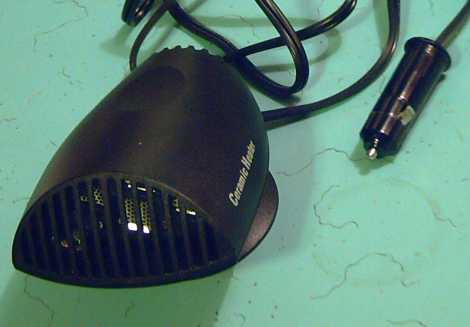
One third of a $90, 36 volt electric car heater with low-profile "Darth Vader" styling.
I bought one to try out - I'll mount it on the dash, and try defogging the windshield next time it needs it while the engine is still cold. The fan seems on the noisy side. (Ack! The cigarette lighter circuit doesn't work, even with a new fuse!)
If three proves insufficient, use six for 900 watts (two switches), at $180 still no more than one 550 watt golf cart heater.
I can already see, however, that the plastic ball pivot mount base is too flimsy to hold the heater aimed where you point it, and there's no way to tighten it. (Now how can I mount them instead that won't cost more than the heaters or take many hours to make?)
The motor controller sends out its power signals based on the positions of the supermagnets on the motor rotor relative to the electromagnets on the stator. There is a light cable from the motor to the controller with five wires for the sensing: ground, power and the three sensor outputs, one for each phase.
I had been using three sets of LEDs and phototransistors, and a slot-solid "can" on the rotor to interrupt the light between to indicate south-north to time each phase.
Then I looked into hall effect magnetic switches. I'd heard of them, and previously read some negative information about them. But when I finally looked on the web and found some datasheets for one type (Allegro Microsystems A1203LUA-T - seemingly exactly the right type) I realized the negative info was obsolete, and that if the whole optical assembly was ditched and replaced with three of these, everything would be simplified and the timing (assuming they were mounted in the proper places) should inherently be "ideal".
Later I realized that the sensors should be mounted between the electromagnets rather than centered on them, to avoid spurious signals when the coils switched on and off in any gaps between supermagnets.
It was hard to make out in the datasheets which way around the leads 1-2-3 went. The diagrams didn't show the critical bottom view which would have clarified the situation. In the confusion of that, my memory of the pin assignments - on an unrelated page entirely - became faulty. I soldered them wrong on the first couple of tries until I finally looked on page 4 again.
Then I found that there was too much "hysteresis" in the switching for the wide gaps between the six supermagnets, and the switching points were actually off too far for good timing. Instead of ideal, they were much worse than the optical unit. I had to move the sensors from the outside of the coils to the inside where the gaps between magnets were smaller. There was also little space, which made everything difficult. I discovered that steel mounting posts worked better than aluminum (steel concentrates the magnetic field), and so I made a second set. I used some RTV rubber cement (orange) to help hold the sensors stable.
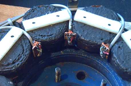
Hall sensors mounted inside. (The steel mounts for the circuit boards are unseen behind.)
EH System Suspension and Vehicle Handling: the new old plan
With the addition of the mechanical torque multiplier, the EH motor system on the car axle increases from around 45 to around 60 pounds. Handling was already adversely affected by 45 pounds mounted solidly on the car axle.
For making new cars, or for wholely electric vehicle conversions, one person's idea of mounting the units on the vehicle chassis and connecting them to the wheels by CV shafts (also adopted by the Oxford University group) seems like the best way to go. However, this isn't possible for an outboard add-on unless it's to protrude a considerable distance.
I started thinking about various spring systems that could allow the EH system to move up and down, or at least to flex up and down. On the 23rd I suddenly realized I've had the key all along! It seems to me that the most practical way to accomplish the flex ability would be something essentially like the system I had on the first motor that moved the car:
* the motor (now motor & torque multiplier assembly) was held in place by the upper and lower arms extending from the brake drum housing or axle. These long arms have a good amount of spring in them.
* the motor turned the wheel by means of a square plate on the end of its axle, which wasn't fixed to the car axle.
* This plate occupied all the space between the four lug nuts on the car wheel, and pushed on all four at once to turn the wheel. Of course, if the wheel went up at a bump, the springy arms will let the outer end of the motor sag momentarily (actually, to not rise with the wheel), and the top of the the central plate would pull out a bit, but would still be "trapped" between the lug nuts.
I thought, when I found the trailer axles that could bolt solidly onto the car's lug bolts, that my first arrangement seemed rather "hoaky" by comparison, but actually it gave the needed spring action, and needs only to be refined.
Refinement details:
* The center plate should be made to fit around the nuts fairly closely, rather than simply between them like the prototype's square plate. (That would reduce or prevent the possibility of jarring it out of the center by too great an angle from a large bump in the road.)
* It may be that CV joint components can be employed. I'll have to study this.
* The farther out the weight of the assembly sits on its axle, the better the spring action - the more effectively the assembly's weight will be sprung. This of course is at odds with trying to minimize the protrusion, but an extra amount (two to five inches?) could make all the difference in vehicle handling.
In addition, reducing the diameter of the motor & assembly could help reduce overall weight. I've been thinking in terms of 9-1/2" or 10" rotors instead of 10-1/2" or 11" regardless, seeing the torque multiplier drum diameter is under 10". 9-1/2" is 22% less rotor surface area (and hence mass) than 10-1/2". There's still room for 12 magnets, and the stator coils could be made a little taller (eg, 1.25" instead of 1") to accommodate the same amount of copper wire and iron in a slightly smaller diameter.
Another weight reduction could be accomplished by using a 1 inch diameter trailer axle instead of 1.125 inch. With various measures, perhaps 10 or more pounds could be trimmed.
Another advantage to this mounting system is that the entire assembly mounts as a single unit. With the axle bolted to the wheel, the torque multiplier and the motor have to be pulled off the axle - disassembled - for installation and removal, eg to change the tire. Not only is this tedious, it involves handling of the loose magnet rotor "in the field", which is hazardous.
The current motor uses six large 2" x 2" x 1/2" supermagnets. Since installing them I've realized there is another reason besides flux distribution to prefer a dozen 2" x 1" x 1/2" magnets, with relatively even spaces between them. (N N S S N N S S N N S S ) That reason is that they make a much better centrifugal fan for blowing air to dissipate heat.
Carried to an extreme, one might opt for two dozen 2" x 1/2" x 1/2" magnet "fins" (or 18 - 2" x 2/3"?), but the twelve "standard" 2" x 1" size blow a pretty good breeze.
Mechanical or Magnetic Torque
Multiplier Project:
Torque Leverage Without Gears
September Details
Torque Leverage Without Gears
September Details
By the end of October, I was nervous that the magnetic design was going to either get magnetically "stuck" and the motor wouldn't be able to start turning, or if the magnetic coupling was sufficiently reduced that the motor could start, it might not have the force to push a car up a hill. Then I had the design idea at the end of October, mentioned in the last newsletter, for a purely mechanical multiplier rather than magnetic.
November saw the details of selecting and buying the most appropriate parts and putting it all together. I thought of a more promising looking magnetic design too, but I continued working on the more certain mechanical model.
But it appeared the pieces I'd assembled for the magnetic version weren't going to be strong enough to handle the loads. In the first days of November, several pieces were considered and rejected or changed in a rapid evolution of the design.
A piece that was briefly considered as the inertic plate - an old cast lamp base.
The feet, chopped to size, fit right into the aluminum pan as driver pins.
But even with the center cut off, it would be too tall. So (though having cut the feet down), I tossed it.
Then I thought of this flat plate, the first EH motor prototype magnet rotor.
The spin driving pins from the motor, represented by these bolts, could be the regular mounting holes.
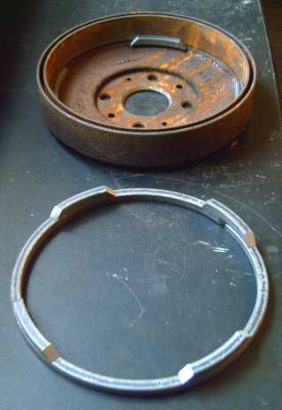
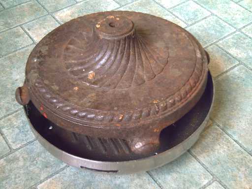
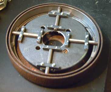
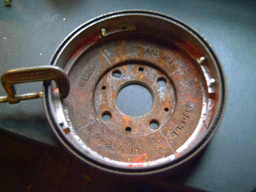
The aluminum frying pan looked rather light-duty for the pounding it would take. The lamp stand led to noticing this drum brake rotor on the shelf.
Let's see: strong enough? yes! shape & size? ideal! Mounts on car axle? made for it!
I don't know why I picked this up when I was selecting suitable disk brake rotors from brake shop garbage cans - I just thought at the time, well... who knows, it might be useful for something! And if I hadn't had it, I'd never have thought of looking for one.
The first plan as shown above was to put ramp pieces on the bottom and the solid ring above the top ramps (ie, it would go in inverted from above view) to prevent the inertia plate from coming out.
Bending the 3/8 inch square bar. I had to redo it from the frying pan diameter to the brake drum diameter, bending it around a smaller circle piece and finally using two big crescent wrenches (12" & 15"). In the crescent wrench metal bending technique, one wrench grips the metal to be bent. The handle sticks out the wrong way, and so a second crescent wrench grips the first one to twist it.
(If I ever see a crescent wrench with the grip at right degrees to the handle, I'm grabbing it!)
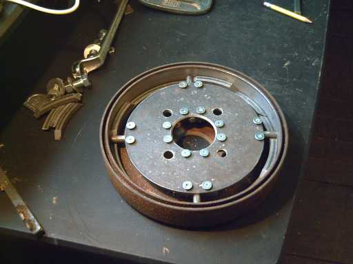
The inertia plate rotor ended up being a circle similar to the above one but smaller, from a metal shop cutting floor, shaped with a grinder and center holes cut with a drill press and by turning on the lathe.
Things were getting tight in all directions.
The protruding hub of the magnet rotor squanders almost an extra inch, as does the finned, hubbed stator plate (also a disk brake rotor). (Now, what was that one rotor I found that the hub was no taller than the magnets and so it could be reversed and take even less space? I wrote it somewhere - some previous newsletter? ...Ah, it's in the motor making manual.)
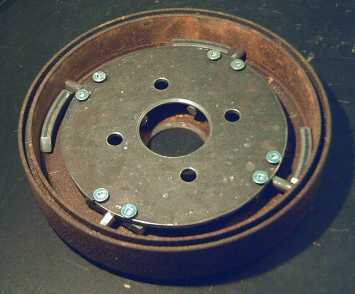
The hands of the clock escapement at 3, 6, 9 and 12.
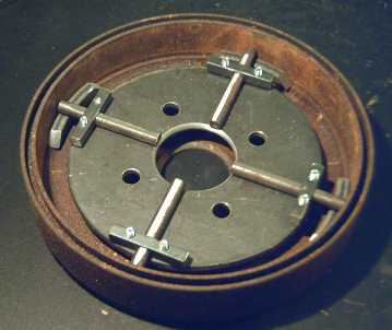
With enough pieces cut to check the fit, positions ended up reversed: The rotor's interior rim was turned down so the ring, now at the bottom, would slip in 1/4" farther. The upper ramps near the top of the rim will need no retaining ring: the inertia plate hits the motor rotor and will go up no farther.
Putting the lower hours on the clock.
The lower ramps were ground down from 3/8" to 1/4" height for clearance reasons.
The bolts (6mm, as 1/4" seemed just a bit too fat) were cut off flush with the angle grinder.
Somehow I happened to have a 6mm threading tap purchased in some previous life (well, probably in the 1970's), and I had the bolts, the sad remains of a cheap back yard gazebo with a fabric roof. (2006 and a wreck in 2 months - I'll never buy one of those again!)
After I decided to do the mechanical version, I had a thought that one might simply replace the ramps with repelling magnets. (No attracting magnets, still using an inertia plate mass as the active piece, probably using something along the lines of the short slots of the previous magnetic design to avoid equal and opposite magnetic counterforces.) That way, there would be no physical hits, just magnetic ones. Since the magnets would sit repelled apart, the static magnetic forces would be too small to hold the motor stalled.
I haven't worked out the finer details as I have less confidence in the efficacy of this design idea than in the mechanical one, which is very simple and can hardly fail to operate.
I have no doubt that a magnetic torque multiplier is perfectly feasible, and probably better than the mechanical one (at least, quieter than my mechanical design), but I'll have to put it on the back burner for now. A mechanical torque converter is far better than anything commercially available today.
October Details
Electrolytes
In studying the book Alkaline Storage Batteries, I went over the history of batteries to see if anything useful could be gleaned. I found that cells had been made using potassium (or sodium) dichromate as a "depolarizer".
In the Poggendorff cell, this was mixed with sulfuric acid electrolyte to make chromic acid. In the Fuller cell it surrounded a carbon electrode (+) and sulfuric acid was used for the zinc (-) electrode in a two-compartment cell (Daniel's cell). (It isn't clear whether the positive fluid was potassium dichromate or chromic acid.)
In addition, there was a sample page reprinted from the notebook of Edison et al from 1875 showing in rather cryptic handwriting what appears to be potassium chlorochromate (and nitric acid?) in the electrolyte. KClCrO3 is the stuff I took some trouble to dissolve out of my last electrodes!
Several types of such cells were made, all around 2 volts.
I put some KClCrO3 back into the positive (nickel hydroxide) electrode, but it didn't seem to do much.
Towards the end of the month I tried adding sulfuric acid to the negative electrode. (Between the electrodes is a layer of agar gel as a salt bridge.) The listed voltage for magnanese(0) to Mn++ in acid is -1.18 volts, almost 1/2 volt better than zinc(0) to Zn++ at -0.72 volts. It fizzed a bit as some Mn powder turned into MnSO4 and gave off H2 gas.
Then I tried charging it. It didn't seem to do much.
I may not have put enough in to work. I didn't get around to another test by month's end.
On thinking about the lead-acid batteries, I noted that they work because metallic lead, lead sulfate, and lead dioxide, the three states of lead found within, are insoluble or only very slightly. Electrode additives are also restricted to heavy elements, eg: antimony, bismuth, tin. Most of the lighter metals and their compounds are soluble in sulfuric acid.
I thought "what about some other acid?" Perhaps there was one that some better electrode metals and their derivatives wouldn't dissolve in. Some common acids I knew wouldn't work, but in the Wikipedia solubility table, it appeared that oxalic acid wouldn't dissolve zinc, copper or nickel, and manganese was very little soluble. Thus, any of these desirable electrode metals could be used in a metal-oxalic acid cell. One "catch" - or perhaps benefit - is that oxalic acid itself, a solid powder, can only be dissolved to 10-15% strength in water, which might make the reactions a bit slow, thus limiting the current capacity. By contrast, sulfuric acid is a liquid that mixes with water and it can be present in any concentration up to 100% acid. (Usually about 33% acid is used. But Plante' originally used 10%.)
But if some oxalic acid powder solidified on the bottom, it would be taken up as the battery discharged, so it shouldn't mean that an excessive amount of water would be needed. In fact, it makes the acid concentration self regulating even though the acid is consumed and generated by the reactions, and a reserve of solidified acid powder under the electrodes (instead of more acid solution) could mean that less water is needed than with lead-sulfuric acid, perhaps even quite minimal water. Of course, having less water further improves energy density.
The electrode reactions (without trying to balance all the O's and H's making up H2O's) would be along the lines of:
[charged <==> discharged]
Nickel (III) oxide + Oxalic acid + e- <==> Nickel (II) oxalate [ +1.5v]
Zinc (0) + Oxalic acid <==> Zinc (II) oxalate + 2e- [-0.72v]
Likewise one could potentially use nickel-nickel, manganese-zinc, nickel-manganese, or manganese-manganese. Theoretically Mn-Mn should be 2.4 volts, which is too high for water based electrodes, but this would vary by acid and the voltage may (or may not) prove good. A combo around 2 volts should be available in there somewhere, hopefully avoiding zinc and its possibly troublesome dendrites formed during charging. These metals are 1/4 to 1/3 the atomic weight of lead (Mn = 55, Pb = 207), significantly reducing battery weight per amp-hour.
I had a bit of oxalic acid powder, so I decided to try it out on the 29th. Zinc in acid is supposed to be -0.72 volts, and I had a rod of zinc. The plus side looked more difficult, especially on a Sunday. I tried mixing a couple of powders and tamping them into a perforated brass tube, but the manganese oxide bubbled and I only saw about 0.9 volts instead of 2, and lanthanum hydroxide gave similar voltage (though no bubbles). I didn't want to take a lot of effort to prepare them properly, and something evidently wasn't working.
Then I got the idea to try a little chunk of the nickel electrode from the Ni-MH battery I'd taken apart quite a while back. It bubbled too, but as it did so the voltage was rising. It seemed to want to charge to about 1.4 - 1.5 volts. Although according to the tables it should have been 2.2 volts in acid, and a couple of suspicious things were going on (perhaps because the nickel electrode was formulated for alkali, not acid - it was losing substance), it does vary from acid to acid.
On December 2nd, it had been sitting at 1.42 volts for two days.
It seems it should be possible to make a workable, chargeable battery based on oxalic acid. Since electrode metals of light atomic weight can be used, and also if the idea of limited water worked out, it might have a notably higher energy density than lead-acid... and who knows about life expectancy before trying out some of the possible electrodes?
Acetic acid (vinegar) might also work, the discharge products being acetates rather than sulfates or oxalates. It's certainly readily available -- IIRC, there's 9% pickling vinegar right on the grocery store shelf! Again, experiments would have to categorize and quantify the practical potentials for transportation batteries.
Being spread much too thin myself, I'll just have my chemical R & D staff investigate further...
The Lead-Acid Battery Renewal Project:
Progress Report
"Trade Secret":
Cunning, secret addition of alum to "top of the line" batteries
I tried renewing a couple of big T-105 golf cart batteries, but not much happened beyond what small improvements might be expected from cycling batteries that had been sitting for some time. And I started to think: I'd heard Pb batteries were good for about 200 cycles. But when I'd enquired a couple of years ago at the beginning of the whole hybridizing project, I remember being told that the golf cart batteries were good for 600 cycles.
I asked at Battery Doctor when I took the T-105s in for recycling to verify my memory, and the fellow read me some printed specs from Trojan for different size "deep cycle" Pb batteries (all specs valid only if never exceeding 60% discharged):
Size 24: 110 or 115 charge-discharge cycles
Size 27: 115 or 120 cycles
T-105: 757 cycles
(The numbers are as best I remembered them - I didn't write them down immediately and I didn't see any "cycle life" specs listed in the battery specs on the Trojan website. But they are very close if not dead on.)
Note the discrepancy: either around 110-120 cycles or way up there. 757 cycles is over six times the life span of 120. And there don't seem to be any in between, eg, around 300 or 450. I've also heard of good results with other "high end" batteries.
So I speculated, could it be that the battery companies quietly put alum or (better) sodium sulfate into their "top of the line" batteries to get the best cycling specs, but just as quietly leave it out of all the "lesser" batteries? Two reasons to do this would be (1) in order to not see a 70-80% drop in sales... and (2) to avoid hostile interest from oil companies, who try very hard to stomp out anything useful for non-petroleum based transportation.
I thought a possible test for this would be to suck up a bit of electrolyte with a hydrometer, and squirt it into a shallow container (plastic jar lid?). IF there's enough sodium sulfate to show up, and if the acid doesn't interfere in some way, it'll form long, thin, translucent needle-like crystals when the water and acid evaporate. It's also possible the amount used just isn't large enough to show up in this way, so the test results are either "positive" or "indeterminate", and can't be conclusively "negative". Having given up the T-105s, to which I had added sodium sulfate myself, I didn't have any "top of the line" batteries to test this way myself. Unfortunately, it seemed to take forever for the evaporation. Perhaps the acid evaporates very slowly compared to water. I got nervous about having probably very concentrated acid sitting in a shallow open container in my shop and finally dumped it. Maybe I'll try again using considerable heat to speed things up.
However, I found a great piece of evidence on line that it is in fact used. I searched for the Chinese patent to see how long the alum treatment has been known - I had the impression it's been around well over 20 years. (I later found out it was known in world war two.) I didn't find it (it's probably in Chinese and who knows if it's on line), but I found a 1991 patent for a lead-acid battery electrode separator sheet specifically for TRACTION/GOLF CART batteries... with ALUM in it. (Deep cycle battery separators, United States Patent 5154988) Since the alum will simply dissolve when the battery is filled, it's actually a very clever way of quietly adding it to the electrolyte. Only a trusted few in the plant where the separators are made, which is doubtless separate from the battery factory, would have any idea there's alum in the batteries.
I finally got sick of turning on car headlight battery loads and then being on an exacting schedule for some considerable time to write down numbers, and then turn them off when the voltage dropped to 11.00 volts, then record a couple of recovery voltages at intervals. And I ruined a very good battery by forgetting about it and leaving it on when I went out. Last month I said I thought it was a job for somebody else. But who?
I decided if I had to run more tests, I'd have to automate the process.
I still use a computer I designed and made about a dozen of in 1986-88 for the Greater Victoria School District, for controlling heating and ventilation and cetera in schools, to control and time a kitchen counter outlet and a couple of stove burners. (That way, I never forget and leave a burner or toaster oven on, and I remember just how long specific cookings take and set them up.)
The Control BASIC language I wrote at the time was rated the very best one by industry insiders, and I decided I'd just have hook up:
* a button to start the test,
* an input to measure the battery voltage,
* a power MOSFET to turn the load on and off,
and write a program to run the entire load test and record the data automatically, turning the load off at the end of the load test and then recording the recovery voltages. At the end, I just have to write down the test result numbers off the screen and recharge the battery.
However, there's a certain amount of work and time required to set this up, too, and I didn't get to it in November.
Using the salt is safer than using sodium hydroxide. I said "15 grams" below, but I'm still not sure what might be an optimum amount to put in. I've tried 15 to 50 grams, and beyond, but somewhere in there is too much.
I'm going now with about 20 grams per cell of anhydrous sodium sulfate for moderate size car batteries, and 30 grams in size 27 "deep cycle" batteries. That's about 3 grams of the salt (per cell) per 5 pounds of battery weight (for 6 cell/12 volt batteries).
1. Buy: face shield (at least eyewear), rubber gloves (grocery), a funnel, and at least 100 grams of anhydrous sodium sulfate salt (compounding pharmacy), preferably more, eg, 500. (You might also find it at a pottery supply, but it may be impure and-or it may (or may not) be hydrated instead of anhydrous, in which case double the weight or four times the volume (2.27 (over double the molecular weight) x 2.66/1.46 (density, g/cc) = ) is required.)
2. Don the eyewear and gloves. This is important - the acid is very corrosive, and you don't want holes in your pants, nasty little red sores on your fingers, or much worse to be severely burned or blinded. (I met a virtually blind chemistry professor recently. Familiarity may breed contempt, but it doesn't lessen the danger.) Old clothes you don't care about are an asset.
3. Remove the covers to open the 6 holes in the top of the battery. Set them on the battery, on cardboard or in a plastic container. Be careful not to splatter anything on yourself. The acid will make holes in your pants and-or in your skin. I've taken to putting a piece of cardboard (or a cardboard box) between me and the battery, so only my gloves, old sweater and face shield are subject to little flying droplets. (I've ruined two pairs of pants so far and have had three small painful sores on fingers.)
4. Check the fluid levels in the battery. If any appear low (eg, tops of plates exposed), add pure water (use the funnel?) to top them up. (If you used the funnel, you then need to dry it.)
5. Using a measuring device (scale, measuring spoons), for a medium car battery (25 - 35 pounds) measure out somewhere around 15 grams, 15 cc or one tablespoon of sodium sulfate. (That's for the anhydrous salt. Use 30 grams, 4 tablespoons for the decahydrate.) Using the funnel, pour it into the first cell. Repeat 5 more times. Don't lose track of which cells you've done. I feel the salt will all dissolve sooner or later so there's no need to mix or stir it in, which has the additional risk of possibly splashing acid.
6. Carefully rinse off the gloves, covers, and any equipment or surface that may have got acid on it. When it seems any percolation has died down, or if there isn't much or any, put on the gloves and eyewear and replace the covers. At this point it's probably advisable to wipe off the tops of the battery(s) with paper towels or a rag (then discard or thoroughly rinse the rag), or simply hose it down if you're doing it out on the lawn.
7. Use the battery.
Note: Percolation seems to be a problem with adding sodium hydroxide solution instead of sodium sulfate. That will form sodium sulfate in the battery, but it seems the procedure corrodes the plates (as well as being somewhat hazardous) and is inadvisable. NEVER add dry sodium hydroxide powder to the acid, or the acid to the powder, in or out of the battery. The reaction is violent and it may fizz up or explode in your face. (Remember the blind chem prof?) It's much the best just to buy and use the ready made salt.
http://www.turquoiseenergy.com
Victoria BC